

Page 1
®
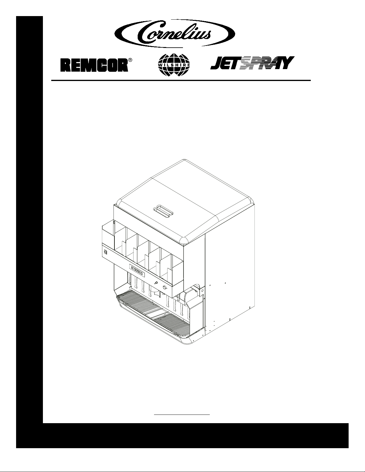
DURAFLEX ICE/BEVERAGE DISPENSER
DF 250 BCP
Operator’s Manual
Release Date: July, 2001
Publication Number: 620919540OPR
Revision Date: October 15, 2002
Revision: A
Control Code: A
Visit the IMI Cornelius web site at www.cornelius.com
for all your Literature needs.
Page 2

Page 3
TABLE OF CONTENTS
START-UP AND OPERATING INSTRUCTIONS . . . . . . . . . . . . . . . . . . . . . . . . . . . . . 2
Controls and Electrical . . . . . . . . . . . . . . . . . . . . . . . . . . . . . . . . . . . . . . . . . . . . . . . 2
Portion Control Panel . . . . . . . . . . . . . . . . . . . . . . . . . . . . . . . . . . . . . . . . . . . . . 2
Portion Control Panel Operations . . . . . . . . . . . . . . . . . . . . . . . . . . . . . . . . . . . . 3
Ice Portion Control Set Up and Adjustment Procedure . . . . . . . . . . . . . . . . . . . . 3
MAINTENANCE . . . . . . . . . . . . . . . . . . . . . . . . . . . . . . . . . . . . . . . . . . . . . . . . . . . . . . . 5
Daily (or as required) . . . . . . . . . . . . . . . . . . . . . . . . . . . . . . . . . . . . . . . . . . . . . . . . . 5
Weekly (or as required) . . . . . . . . . . . . . . . . . . . . . . . . . . . . . . . . . . . . . . . . . . . . . . . 5
Monthly . . . . . . . . . . . . . . . . . . . . . . . . . . . . . . . . . . . . . . . . . . . . . . . . . . . . . . . . . . . 5
Cleaning Instructions . . . . . . . . . . . . . . . . . . . . . . . . . . . . . . . . . . . . . . . . . . . . . . . . . 5
Dispenser . . . . . . . . . . . . . . . . . . . . . . . . . . . . . . . . . . . . . . . . . . . . . . . . . . . . . . 5
BEVERAGE SYSTEM. . . . . . . . . . . . . . . . . . . . . . . . . . . . . . . . . . . . . . . . . . . . . . . . . . . 7
Cleaning . . . . . . . . . . . . . . . . . . . . . . . . . . . . . . . . . . . . . . . . . . . . . . . . . . . . . . . . . . 7
Cleaning Dispensing Valves . . . . . . . . . . . . . . . . . . . . . . . . . . . . . . . . . . . . . . . . 7
Sanitizing . . . . . . . . . . . . . . . . . . . . . . . . . . . . . . . . . . . . . . . . . . . . . . . . . . . . . . . 7
Sanitize tank systems, Post-Mix and Pre-Mix . . . . . . . . . . . . . . . . . . . 7
Sanitize syrup lines, B-I-B Systems. . . . . . . . . . . . . . . . . . . . . . . . . . . 7
TROUBLESHOOTING . . . . . . . . . . . . . . . . . . . . . . . . . . . . . . . . . . . . . . . . . . . . . . . . . . 9
Trouble . . . . . . . . . . . . . . . . . . . . . . . . . . . . . . . . . . . . . . . . . . . . . . . . . . . . . . . . . . . 9
Probable Cause . . . . . . . . . . . . . . . . . . . . . . . . . . . . . . . . . . . . . . . . . . . . . . . . . . . . 9
Remedy . . . . . . . . . . . . . . . . . . . . . . . . . . . . . . . . . . . . . . . . . . . . . . . . . . . . . . . . . . . 9
WARRANTY . . . . . . . . . . . . . . . . . . . . . . . . . . . . . . . . . . . . . . . . . . . . . . . . . . . . . . . . . 11
© 2001-02, IMI Cornelius Inc. - i - Publication Number: 620919540OPR
Page 4

Publication Number: 620919540OPR - ii - © 2001-02, IMI Cornelius Inc.
Page 5
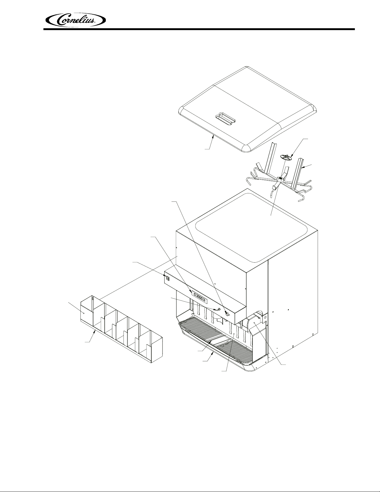
ICE BIN COVER
MANUAL ICE DISPENSE
RED PUSH BUTTON SWITCH
Duraflex Ice/Beverage Dispenser Operator’s Manual
RETAINER
ICE AGITATOR
REMOVABLE STRAW
HOLDER PANEL
LID/STRAW
HOLDER
ICE PORTION
CONTROL MODULE
BEVERAGE FAUCET
ON/OFF SWITCH
MANUAL/AUTO ICE
TOGGLE SWITCH
CUP REST
DRIP TRAY
LOWER ACCESS
PANEL
FIGURE 1. PARTS IDENTICATION
BEVERAGE FAUCETS (8)
© 2002, IMI Cornelius Inc. - 1 - Publication Number: 620919540OPR
Page 6
Duraflex Ice/Beverage Dispenser Operator’s Manual
START-UP AND OPERATING INSTRUCTIONS
Fill the hopper with ice and replace the lid. Allow 10 to 15 minutes for the cold plate to cool down. Repeat
this procedure whenever the dispenser has been standing overnight or other long periods without ice
use. Start up the beverage system and adjust faucets to the proper brix. Contact your local syrup distributor for complete information on the beverage system.
To dispense ice, hold cup under ice chute and press the appropriate size button on the ice portion control
located above the ice chute. An extra ice portion may be obtained by pressing the increase key before
pressing the button.
For beverage dispensing, place a cup on the cup rest against the faucet lever of the desired flavor. Beverage will be dispensed automatically filling the cup and shutting off. A delay feature is provided in the
faucet controller to “top-off” the drink after shut off.
CAUTION: Use caution to avoid spilling ice when filling dispenser. Clean up immediately any
spilled ice from filling or operating the unit. To prevent contamination of ice, the lid must be
installed at the unit at all times.
If the dispenser fails to dispense ice or beverage, see troubleshooting guide.
CONTROLS AND ELECTRICAL
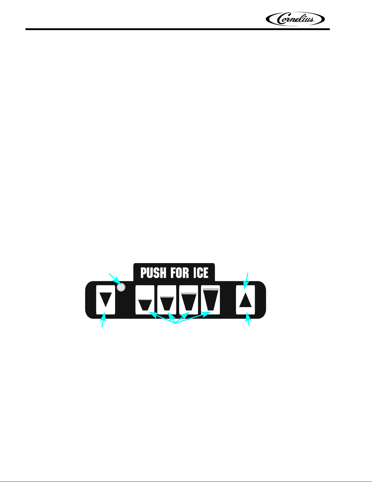
Portion Control Panel
The portion control panel on the Pro ED Fast Gate has several functions including dispensing 4 programmed ice portions for 4 cup sizes, programming, and cleaning. The portion control panel and its functionality are described in the following illustration:
LIGHT
Indicates mode of
operation or amount
of adjustment
DECREASE
CUP SIZE
Small, Medium, Large or X-Large Cup Size
Press for extra
ice, then press
cup size
INCREASE
Publication Number: 620919540OPR - 2 - © 2002, IMI Cornelius Inc.
Page 7

Duraflex Ice/Beverage Dispenser Operator’s Manual
Portion Control Panel Operations
Light Color Explanation Actions That Can Be Taken
Green Normal
Green - flashing Normal
Red then
Yellow Clean Mode To enter Clean Mode simultaneously press
Operation
Operation
Chute Refilling
Press any
Press
extra ic e.
Wait until chute has refilled and press
desired
INCREASE and DECREASE.
Press any CUP SIZE to empty chute, then remove chute for cleaning.
When chute is replaced, unit will aut omatically return to normal operation after one
minute, or
simultaneously pressed 3 times.
CUP SIZE for portioned ice.
— or —
INCREASE and then CUP SIZE for
CUP SIZE again.
INCREASE and DECREASE can
Ice Portion Control Set Up and Adjustment Procedure
Light Color Explanation Actions That Can Be Taken
Step 1. Fill the Ice Chute
Yellow
Flashing
Chute Agitation Refill
Time
To enter Agitation Adjustment Mode simultaneously press
three times then press and hold
and DECREASE for 3 seconds.
Press any CUP SIZE to select a preset agitation time (small=shortest time, XLarge=longest time, ect)
To exit Agitation Refill Time Adjustment
Mode simultaneously press
DECREASE.
NOTE: Once in a mode the light will blink to
indicate the refill time: 1 blink for the shortest refill time-4 blinks for the longest refill.
The factory recommendation is 2 blinks.
NOTE: Larger ice portions require more time to refill.
INCREASE and DECREASE
INCREASE
INCREASE and
© 2002, IMI Cornelius Inc. - 3 - Publication Number: 620919540OPR
Page 8

Duraflex Ice/Beverage Dispenser Operator’s Manual
Light Color Explanation Actions That Can Be Taken
Step 2. Set portion level for each size cup
Step 3. If
desired, set
the extra ice
portion adjustment
Yellow Ice Portion
Adjustment
To enter Portion Adjustment Mode simultaneously press
twice.
Press and hold
and while pr essing INCREASE or DECREASE
to change portion size (5 millisecond per
pulse).
NOTE: Make sure the light blinks as the buttons are pressed.
The light will flash green for 5 seconds.
While the green light is flashing the ice portion can be tested by pressing the
SIZE again.
To exit Portion Adjustment Mode simultaneously press
two times.
Red Extra Ice Por-
tion Adjustment
To enter Extra Ice Adjustment Mode simultaneously press
three times.
Press and hold the
adjusted and press
DECREASE to change portion si ze
(5 millisecond per pulse).
NOTE: Make sure the light blinks as the buttons are pressed.
To exit Extra Ice Portion Adjustment Mode
simultaneously press
DECREASE.
INCREASE and DECREASE
CUP SIZE to be adjusted
CUP
INCREASE and DECREASE
INCREASE and DECREASE
CUP SIZE to be
INCREASE or
INCREASE and
NOTE: Consult store manager on desired ice level in each size cup.
CAUTION: The gate closes immediately when the toggle switch is moved to the auto position. Do
not place fingers or foreign objects into the ice chute when operating the toggle switch.
Publication Number: 620919540OPR - 4 - © 2002, IMI Cornelius Inc.
Page 9

The following dispenser maintenance should be performed at the intervals indicated.
DAILY (OR AS REQUIRED)
Remove foreign material from vending area drip tray to prevent drain blockage.
WEEKLY (OR AS REQUIRED)
Clean vending area. Check for proper water drainage from the vending area drip tray.
MONTHLY
Clean and sanitize the hopper interior and beverage system if applicable (see CLEANING INSTRUCTIONS).
CLEANING INSTRUCTIONS
WARNING: Disconnect Power Before Cleaning! Do not use metal scrapers, sharp objects or abrasives on the ice storage hopper, top cover, ice chute, and air cylinder access cover as damage
may result. Do not use solvents or other cleaning agents, as they may attack the plastic material.
Duraflex Ice/Beverage Dispenser Operator’s Manual
MAINTENANCE
Soap solution
Sanitizing solution
tizing solution to this ratio will create a solution of 200 PPM.
Dispenser
1. CLEANING EXTERIOR SURFACES
IMPORTANT: Perform the following daily.
A. Remove the cup rest from drip tray.
B. Wash the drip tray with soap solution. Rinse with clean water and allow solution to run down the
C. Wash cup rest with soap solution and rinse in clean water. Install the cup rest into the drip tray.
D. Clean all exterior surfaces with soap solution and rinse in clean water.
2. CLEANING INTERIOR SURFACES
CAUTION: When pouring liquid into the hopper, do not exceed the rate of 1/2 gallon per minute.
CAUTION: It will be necessary to have electrical power on to the unit in order to remove any
remaining ice from the stora ge hopper and ice chute. After the ice has been remove d, disconne ct
electrical power to the unit before proceeding with cleaning and sanitizing.
A. Dispense all ice from the hopper and ice chute by switching the auto/manual toggle switch to the
B. IMPORT ANT : Disconnect electrical power to the unit for the remainder of the cleaning and sanitiz-
C. Cold plate inspection before cleaning.
- use a mixture of mild detergent and warm 100 degrees F potable water.
- use 1/2 ounce of household bleach in 1 gallon of potable water. Preparing the sani-
drain.
“manual” position. The gate slide will then be held open to empty the ice chute. Depress the red
manual pushbutton switch to dispense all remaining ice from the hopper. Discard the ice. Return
the toggle switch to the “auto” position to close the gate slide.
ing procedure.
1. Remove splash panel.
2. Remove the plastic cold plate access cover to expose the cold plate.
3. Remove any remaining ice from the cold plate surface and discard.
4. Locate and remove any debris from the cold plate, drain trough and make certain that the
drain holes are not clogged.
5. Reinstall the cold platecover.
6. Reinstall the splash panel.
© 2002, IMI Cornelius Inc. - 5 - Publication Number: 620919540OPR
Page 10

Duraflex Ice/Beverage Dispenser Operator’s Manual
D. Remove the plastic lid, agitator retainer (turn counterclockwise to unscrew), and agitator from
the ice storage hopper.
E. Using a long handle nylon bristle brush, clean the interior of the hopper and cold plate with the
soap solution. The cold plate can be reached by going through the ice opening on the hopper bottom. Make certain to reach the entire surface of the cold plate including the corners. Thoroughly
rinse the hopper interior and cold plate with clean potable water.
F. Clean the agitator, agitator retainer, and lid with the soap solution. Thoroughly rinse with clean
potable water. Reassemble the agitator and retainer in the hopper. Make sure that the retainer is
secured tightly (turn clockwise to screw in place).
G. Clean and sanitize the ice chute as described below:
1. Remove the ice chute cover (snap-fit) by spreading the sides apart slightly to disengage the
tabs in the cover from the ice chute and sliding down to remove the cover. The ice chute (rear
half) and the ice gate are now exposed for cleaning.
2. Remove the black plastic access cover for the air cylinder from the splash panel (2 thumbscrews).
3. Wash the ice chute cover, ice chute (rear half), ice gate, and air cylinder access cover with the
soap solution. Thoroughly rinse with clean potable water.
4. Using a mechanical spray bottle filled with sanitizing solution, spray these parts with sanitizer.
Allow to air dry.
5. Reassemble the ice chute cover and air cylinder access cover.
H. Using the mechanical spray bottle filled with sanitizing solution, spray the entire hopper interior,
agitator assembly, and hopper lid. Allow to air dry. Replace the lid on the unit.
Publication Number: 620919540OPR - 6 - © 2002, IMI Cornelius Inc.
Page 11

CLEANING
Soap solution - Use a mixture of mild detergent and warm 100 degrees F potable water.
Duraflex Ice/Beverage Dispenser Operator’s Manual
BEVERAGE SYSTEM
Sanitizing solution
tizing solution to this ratio will provide the required solution of 200 PPM.
Cleaning tank
degrees F potable water.
- Use 1/2 ounce of household bleach in 1 gallon of potable water. Preparing the sani-
- Fill clean, empty tank with a mixture of mild detergent and five (5) gallons of warm 120
Cleaning Dispensing Valves
Refer to addendum supplied with the unit that is applicable to the manufacturer of the valves installed on
the unit.
Sanitizing
IMPORTANT: Only trained and qualified persons should perform these cleaning and sanitizing
procedures.
Sanitize tank systems, Post-Mix and Pre-Mix
1. Remove all the quick disconnects from all the tanks. Fill a suitable pail or bucket with soap solution.
2. Submerge all disconnects (gas and liquid) in the soap solution and then clean them using a nylon
bristle brush. (Do not use a wire brush). Rinse with clean water.
3. Prepare sanitizing solution and using a mechanical spray bottle, spray the disconnects. Allow to air
dry.
4. Using a clean, empty tank, prepare five (5) gallons of the sanitizing solution. Rinse the tank disconnects with approximately 9 oz. of the sanitizing solution. Close the tank.
5. Prepare cleaning tank by filling clean five (5) gallon tank with a mixture of mild detergent and 120
degrees F potable water.
6. Connect a gas disconnect to the tank and then apply one of the product tubes to the cleaning tank.
Operate the appropriate valve until liquid dispensed is free of any syrup.
7. Disconnect cleaning tank and hook up sanitizing tank to syrup line and CO
8. Energize beverage faucet until chlorine sanitizing solution is dispensed through the faucet. Flush at
least two (2) cups of liquid to insure that the sanitizing solution has filled the entire length of the
syrup tubing.
9. Allow sanitizer to remain in lines for fifteen (15) minutes.
10. Repeat the step above, applying a different product tube each time until all tubes are filled with the
sanitizing solution.
11. For post-mix valves, remove the nozzle and syrup diffuser and clean them in a mild soap solution.
Rinse with clean water, then reinstall the nozzle and syrup diffuser on the valve.
12. For pre-mix valves, disconnect all product tubes from the tank of sanitizing solution and then open
the valves to allow the pressure to be relieved. Remove the valv es from the dispenser, disassemble
and wash thoroughly in a mild soap solution.
13. Rinse the parts in clean water, reassemble the valve and reconnect it to the dispenser.
14. Discard the tank of sanitizing solution and reconnect the product (syrup or pre-mix) tanks. Operate
the valves until all sanitizer has been flushed from the system and only product (syrup or pre-mix) is
flowing.
2 system.
Sanitize syrup lines, B-I-B Syst ems
1. Remove all the quick disconnects from all the B-I-B containers.
2. Fill a suitable pail or bucket with soap solution.
3. Submerge all disconnects (gas and liquid) in the soap solution and then clean them using a nylon
bristle brush. (Do not use a wire brush). Rinse with clean water.
4. Using a plastic pail, prepare approximately five (5) gallons of sanitizing solution.
© 2002, IMI Cornelius Inc. - 7 - Publication Number: 620919540OPR
Page 12

Duraflex Ice/Beverage Dispenser Operator’s Manual
5. Rinse the B-I-B disconnects in the sanitizing solution.
6. Sanitizing fittings must be attached to each B-I-B disconnect. If these fittings are not available, the
fittings from empty B-I-B bags can be cut from the bags and used. These fittings open the disconnect so the sanitizing solution can be drawn through the disconnect.
7. Place all the B-I-B disconnects into the pail of sanitizing solution. Operate all the valves until the
sanitizing solution is flowing from the valve. Allow sanitizer to remain in lines for fifteen (15) minutes.
8. Remove the nozzle and syrup diffuser from each valve and clean them in a soap solution. Rinse
with clean water and reassemble the nozzle and syrup diffuser to the valve.
9. Remove the sanitizing fittings from the B-I-B disconnects and connect the disconnects to the appropriate B-I-B container. Operate the valves until all sanitizer has been flushed from the system and
syrup is flowing freely.
Publication Number: 620919540OPR - 8 - © 2002, IMI Cornelius Inc.
Page 13

Duraflex Ice/Beverage Dispenser Operator’s Manual
TROUBLESHOOTING
IMPORTANT: Only qualified personnel should service internal components or electrical wiring.
WARNING: If repairs are to be made to the beverage system, remove quick disconnects from the
applicable product tank, then relieve the system pressure before proceeding. If repairs are to be
made to the C
before proceeding. If repairs are to be made to the ice dispensing system, make sure electrical
power is disconnected from the unit.
TROUBLE PROBABLE CAUSE REMEDY
NOTE: Should your unit fail to operate properly, check that there is power to the unit and that the
hopper contains ice. If the unit does not dispense, check the following chart under the appr opriate symptom(s) to aid in locating the defect.
BLOWN FUSE OR CIRCUIT BREAKER.
SLUSHY ICE. WATER IN HOPPER
BEVERAGES DO NOT DISPENSE.
BEVERAGES TOO SWEET. A. Carbonator not working. A. Check carbonator.
BEVERAGES NOT SWEET ENOUGH.
BEVERAGES NOT COLD (UNITS WITH BUILD-IN COLD PLATE).
NOTE: Contact y o ur local syrup or be verage equipment distr ibutor f or a dditional inf ormation and
trouble shooting of beverage system.
NO ICE DISPENSED FROM ICE PORTION CONTROLLER
O2 system, stop dispensing, shut off the CO2 supply, then relieve the system pressure
A. Short circuit in wiring (115V circuit). A. Replace defective wiring.
B. Defective agitator motor. B. Replace agitator motor.
A. Blocked drain. A. Open-up/flush out drain.
B. Unit not level. B. Level unit.
C. Poor ice quality due to water quality
or ice maker problems.
D. Improper use of flaked ice. D. Replaced flaked ice with “cube
A. No 24 volt power to faucets. A. Check that beverage switch is
B. No CO2 pressure. B. Check CO2 regulator. Check
B. No CO2 pressure in carbonator. B. Check CO2 regulator. Check
C. Faucet brix requires adj us tin g. C. Brix Faucet.
A. Empty syrup tank. A. Refill syrup tank.
B. Faucet Brix requires adjusting. B. Brix Faucet.
A. Unit standing with no ice in hoppe r -
no ice in col d plate cabinet.
A. Insufficient ice supply in ice bin. A. Replenish ice supply as
B. Ice in ice bin bridged (stuck together).B. Gently tap on ice to break it
C. No electrical power to dispenser. C. Plug in dispenser power cord, or
D. Insufficient or no CO2 supply to dis-
penser.
E. Ice chute cover not properly installed.E. Make sure that cover is
F. Defective ice chute interlock switch. F. Replace interlock switch.
G. Defective interlock relay. G. Replace relay.
C. Install water filter system. For
Icemaker problems, consult icemaker manual.
style ice (see page 2, Unit
Description).
“on”. Check 24V transformers.
CO2 tank pressure.
CO2 tank pressure.
A. Refill hopper with ice.
required.
loose.
check fuse or circuit breaker.
D. Restore CO2 supply to dis-
penser.
“snapped” into place.
© 2002, IMI Cornelius Inc. - 9 - Publication Number: 620919540OPR
Page 14

Duraflex Ice/Beverage Dispenser Operator’s Manual
TROUBLE PROBABLE CAUSE REMEDY
NO ICE DISPENSED FROM
ICE PORTION CONTROLLER (Continued)
NO ICE DISPENSED FROM MANUAL ICE DISPENSE PUSHBUTTON SWITCH
ICE DISPENSING DURING AUTOMATIC AGITATION
H. Defective 24V transformer. H. Replace transformer.
I. Defective portion controller. I. Replace controller.
J. Defective ice gate cylinder. J. Replace cylinder.
K. Defective ice gate solenoid valve. K. Replace solenoid valve.
L. Agitation relay wiring incorrect. L. Red wire should be connected to
M. Defective agitation relay. M. Replace relay.
N. Defective agitator motor start capaci-
tor or start relay.
A. Manual/Auto toggle switch in “Auto”
position.
B. Insufficient or no CO2 supply to dis-
penser.
C. Defective 24VAC transformer. C. Replace Transformer.
D. Defective manual override solenoid
valve.
E. Defective manual ice dispense push-
button switch.
F. Defective agitator motor or start
capacitor or start relay.
G. Defective ice gate cylinder. G. Replace cylinder.
A. Manual/Auto toggle switch in “man-
ual” position.
B. Defective ice gate cylinder. B. Replace cylinder.
C. Defective ice gate solenoid valve. C. Replace valve.
D. Defective portion controller. D. Replace controller.
“+” terminal (#3) of relay coil.
N. Replace defective component.
A. Move toggle switch to “Manual”
position.
B. Restore CO2 supply to dis-
penser.
D. Replace valve.
E. Replace switch.
F. Replace defective component.
A. Move toggle switch to “auto”
position.
Publication Number: 620919540OPR - 10 - © 2002, IMI Cornelius Inc.
Page 15

Duraflex Ice/Beverage Dispenser Operator’s Manual
WARRANTY
IMI Cornelius Inc. warrants that all equipment and parts are free from defects in material and
workmanship under normal use and service. For a copy of the warranty applicable to your Cornelius, Remcor or Wilshire
office nearest you. Please provide the
chase.
IMI Cornelius Offic es
AUSTRALIA D P.O. 210, D RIVERWOOD , D NSW 2210, AUSTRALIA D (61) 2 533 3122 D FAX (61) 2 534 2166
AUSTRIA
BELGIUM
BRAZIL
ENGLAND
FRANCE
GERMANY
GREECE
HONG KONG
ITALY
NEW ZEALAND
SINGAPORE
SPAIN
FAX (34) 3 654 3379
USA
LD004
4/21/98
D AM LANGEN FELDE 32 D A-1222 D VIENNA, AUSTRIA D (43) 1 233 520 D FAX (43) 1-2335-2930
D BOSKAPELLEI 122 D B-2930 BRAASCHAAT, BELGIUM D (32) 3 664 0552 D FAX (32) 3 665 2307
D RUA ITAOCARA 97 D TOMAS COELHO D RIO DE JANEIR O, BRAZIL D (55) 21 591 7150 D FAX (55) 21 593 1829
D TYTHING ROAD ALCESTER D WARWICKSHIRE, B49 6 EU, ENGLAND D (44) 789 763 101 D FAX (44) 789 763 644
D 71 ROUTE DE ST. DENIS D F-95170 DEUIL LA BARRE D PARIS, FRANCE D (33) 1 34 28 6200 D FAX (33) 1 34 28 6201
D CARL LEVERKUS STRASSE 15 D D-4018 LANGENFELD, GERMANY D (49) 2173 7930 D FAX (49) 2173 77 438
D 488 MESSOGION AVENUE D AGIA PARASKEVI D 153 42 D ATHENS, GREECE D (30) 1 600 1073 D FAX (30) 1 601 2491
D 1104 TAIKOTSUI CENTRE D 11-15 KOK CHEUNG ST D TAIKOKTSUE, HONG KONG D (852) 789 9882 D FAX (852) 391 6222
D VIA PELLIZZARI 11 D 1-20059 D VIMARCATE, ITALY D (39) 39 608 0817 D FAX (39) 39 608 0814
D 20 LANSFORD CRES. D P.O. BO X 19-044 A VONDALE D AUCKLAND 7, NEW Z EALAND D (64) 9 8200 357 D F AX (64) 9 8200 361
D 16 TUAS STREET D SINGAPORE 2263 D (65) 862 5542 D FAX (65) 862 5604
D POLIGONO INDUSTRAIL D RIERA DEL FONOLLAR D E- 08830 SANT BO I DE LLOBREG AT D BARCELONA, SPAIN D (34) 3 640 2839 D
D ONE CORNELIUS PLACE D ANOKA, MINNESOTA D (763) 421-6120 D F AX (763) 422-3255
product, in your country, please write, fax or telephone the IMI Cornelius
equipment model number, serial number and the date of pur-
© 2002, IMI Cornelius Inc. - 11 - Publication Number: 620919540OPR
Page 16

Duraflex Ice/Beverage Dispenser Operator’s Manual
Publication Number: 620919540OPR - 12 - © 2002, IMI Cornelius Inc.
Page 17

Page 18

IMI Cornelius Inc.
One Cornelius Place
Anoka, MN 55303-1592
U.S.A.
 Loading...