

Page 1
Remcor Incorporated
500 Regency Drive
Glendale Heights, IL 60139
Telephone (708) 980-6900
Facsimile (708) 980-8511
FOR
CONNECTING REYNOLDS CF-6-TT ICEMAKER
TO
REMCOR TJ45/90/200-A, --AB, --ABC DISPENSER
CAUTION: Disconnect power before installation of tube kit.
1. Refer to the respective model owner’s manual (template drawings) for locating the openings in the counter
for the ice feed tube, icemaker control bulb, and utilities.
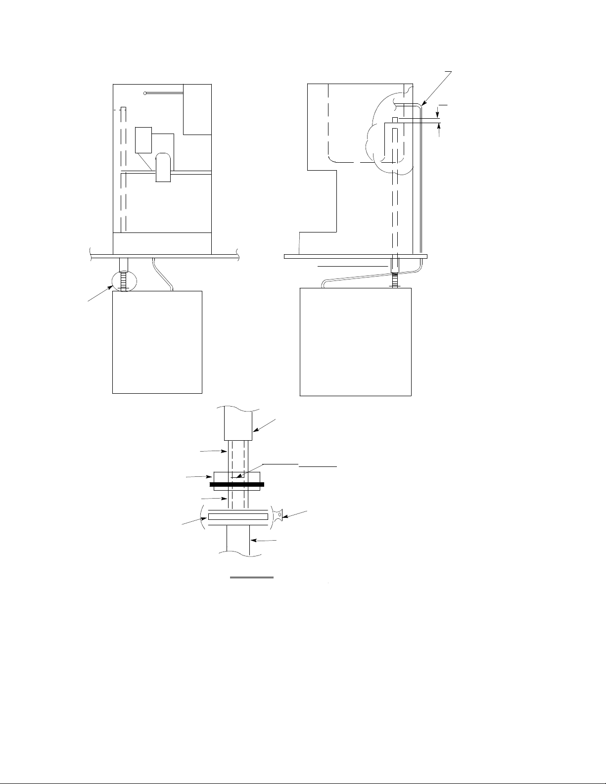
2. Clamp metal fitting and gasket to icemaker evaporator as shown.
3. Carefully remove the deflector assembly inside the hopper. Feed the dispenser end of the tube up through
the counter and cabinet and into the hopper.
4. Temporarily position feed tube on to the icemaker fitting until completely seated. Adjust icemaker position
as required. Check feed tube extension inside hopper. Mark tube to trimming to provide 1? extension. Remove the feed tube, and cut as marked, being sure to remove any burrs or rough edges. Slide the insulation on the feed tube; reinstall feed tube in dispenser and clamp feed tube to icemaker fitting as shown.
5. Route the icemaker, control bulb along the outside of the dispenser rear cabinet, and into the hopper as
shown. The minimum bulb lengths required are:
TJ45/90 -- 6 ft.
TJ200 -- 8 ft.
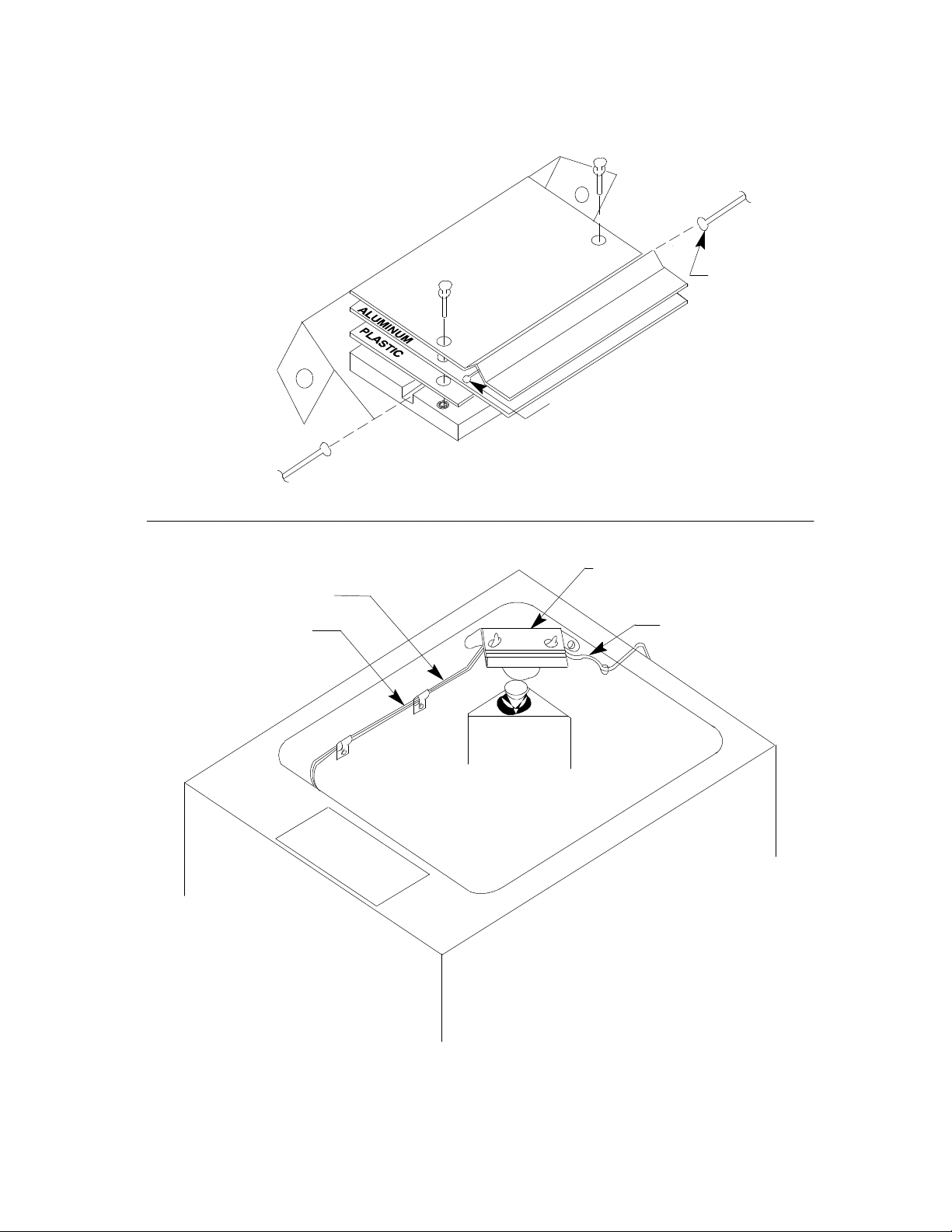
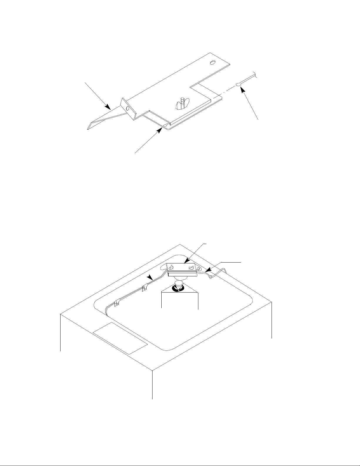
Install insulating tubing and mount the bulb to the deflector assembly . Be careful to avoid damaging or kinking the bulb capillary tubing. Do not allow the bulb to contact any cold surfaces or false sensing will occur.
Route the bulb away from electrical terminals, moving parts or sharp metal edges.
6. Seal ice tube to hopper using a food grade sealant such as DOW 720 series RTV. Follow all marking to
the icemaker and instructions provided with both the icemaker and dispenser.
1
90661
Page 2
ROUTE ICEMAKER
BULB AS SHOWN
INSIDE
DETAIL
“A”
DISPENSER
INSULATION
ICEMAKER ICEMAKER
INSULATION
FEED
TUBE
PVC
COUPLING
METAL
FITTING
GASKET
FEED TUBE MUST BE
FLUSH AGAINST METAL
ICEMAKER
EVAPORATOR
DISPENSER
WARNING
FITTING
CLAMP
90661
DETAIL “A”
FIGURE 1. INSTALLATION
2
Page 3
STAINLESS
DEFLECTOR
END OF INSTALLED
BULB PROTRUDES
AGITATION
BULB -BOTTOM
ALUMINUM
PLATE
APPROX 1/4? TYPICAL
FIGURE 2. DEFLECTOR ASSEMBLY TJ45--A AND TJ90--A MODELS
DEFLECTOR ASSEMBLY
AGITATION BULB
INSTALL BARE BULBS
AS SHOWN ABOVE
ICEMAKER
BULB -- TOP
INSULATING TUBING
UP TO DEFLECTOR
ICEMAKER BULB
WITH INSULATION
TUBING UP TO
DEFLECTOR
FIGURE 3. HOPPER INTERIOR TJ45--A AND TJ90A MODELS
3
90661
Page 4
STAINLESS
DEFLECTOR
ICEMAKER
BULB
END OF INSTALLED
BULB PROTRUDES
APPROX. 1/4-IN
DEFLECTOR ASSEMBLY
INSTALL BARE BULBS
AS SHOWN ABOVE
ICEMAKER BULB
WITH INSULATION
TUBING UP TO
DEFLECTOR
90661
FIGURE 4. DEFLECTOR ASSEMBLY AND HOPPER INTERIOR FOR TJ200--A
4
 Loading...