


Řídicí systém pro
vzduchotechnické jednotky
INSTALLATION AND OPERATING INSTRUCTIONS
Control units
11 /2018


1
Control units VCS
Table of Contents
n e VCS control unit soware is the intellectual property
of REMAK a.s.
n VCS control units are manufactured in accordance with
valid Czech and European regulations and technical standards.
n VCS control units must be installed and used only in accor-
dance with this documentation.
n The manufacturer is not responsible for any damage resul-
ting from use for purposes other than specified in this documentation, and the customer bears the risks of such use.
n The installation and operating documentation must be
available for the operating and servicing staff. It is advisable to store this documentation close to the installed
VCS control unit.
n When handling, installing, wiring, commissioning, repairing
or servicing the air-handling units, it is necessary to observe
valid safety rules, standards and generally recognized
technical rules.
n All equipment connections must comply with the respective
safety standards and regulations.
Introduction
Equipment characteristics .................................................................................................................................................................2
Design .......................................................................................................................................................................................................3
Documentation and Safety Measures ...........................................................................................................................................4
Handling, Transport and Location ................................................................................................................................................... 5
Commissioning ......................................................................................................................................................................................6
Control and Protection Functions ................................................................................................................................................... 8
Basic Operating Modes ...................................................................................................................................................................17
Additional Operating Modes and Functions ............................................................................................................................. 17
Temperature and Time Modes ......................................................................................................................................................19
Control (HMI-SG controller) ............................................................................................................................................................20
List of Data Points (HMI-SG controller) ...................................................................................................................................... 27
List of Failures (HMI-SG controller) ..............................................................................................................................................43
REMAK mobile app ...........................................................................................................................................................................47
Control (HMI-DM, HMI-TM and HMI@Web controllers) ........................................................................................................46
Control (HMI@Web – Installation and Connection to PC and LAN/WAN) ....................................................................51
SCADA (Supervisory Control and Data Acquisition) .............................................................................................................. 58
List of Data Points (HMI-DM, HMI-TM and HMI@Web controller) ...................................................................................59
List of Failures (HMI-DM, HMI-TM and HMI@Web controller) ............................................................................................ 68
Other Control ......................................................................................................................................................................................69
Connection to the Master System (LonWorks Standard) ................................................................................................... 70
Connection to the Master System (ModBus Standard) ....................................................................................................... 75
Connection to the Master System (BacNet Standard) ........................................................................................................95
POOL UNITS – descriptioon of control ...................................................................................................................................... 97
PLC Controller for Compressor Output Control ......................................................................................................................99
Electronic Expansion Valve Overheating Controller EC3-X33 ......................................................................................... 104
KHD-S1_ _.R Backup System Wiring Diagram....................................................................................................................110
Unit Activation ................................................................................................................................................................................. 111
Checks and Failures ........................................................................................................................................................................ 113
Troubleshooting .............................................................................................................................................................................. 114
Spare Parts and Service ...............................................................................................................................................................115
Disposal and Recycling ................................................................................................................................................................. 115
n Any changes or modifications to individual components of
the VCS control unit which could affect its safe and proper
functioning are forbidden.
n Before installing and using the air-handling units, it is nece-
ssary to familiarize yourself with and observe the directions
and recommendations included in the following chapters.
n The VCS control units, including their individual parts,
are not intended, due to their concept, for direct sale
to end customers. Each installation must be performed
in accordance with a professional project created by
a qualified designer who is responsible for the proper
selection and dimensioning of components concerning
their suitability for a given application. Installation and
commissioning may only be performed by an authorized
company licensed in accordance with generally valid
regulations.
n REMAK a.s. is not responsible for any damage, direct or
indirect, caused by unauthorized or unqualified used of
the soware or hardware, or for any damage caused by
ignoring the product's Operating Instructions.
Up-to-date version of this document is available at website www.remak.eu
2
Equipment characteristics
Application
VCS control units are compact control and power distributors used for the decentralized regulation and control of airhandling systems. ey provide the equipment with high
stability and safety while allowing easy control, including the
viewing of operating states. (STOP - OPERATION - AUTO).
Main Features
e VCS control unit is intended for the following:
n Complex autonomous control of air-handling systems
n Supply or room air temperature control (cascade control)
n Supply and power actuation of air-handling systems
n Protection and safeguarding of connected components
is control unit provides air-handling systems with control
and safety functions. It can be equipped with the necessary
number of proportional inputs and outputs depending on the
required functions.
Sophisticated control algorithms ensure system stability, user-friendly control and energy savings. Another
advantage is that the control unit's features also contribute to energy savings in air-handling system operation:
n Option to set the unit to 2 temperature modes
• Comfort
• Economy
n Time schedule setting options
(daily or weekly time schedules)
n Additional operating mode setting options:
• Optimized start
• Temperature start-up
• Night chilling
n Precise drive control using data communications
(Modbus RTU protocol)
n Superior antifreeze protection with moderate heating of
the heat exchanger during standby mode
n Precise analogue control of controlled peripheral units
(according to the controlled component)
Unit Design
ese control units are designed in accordance with ČSN
EN 60204-1. e unit's control and power parts are situated in a single box. e components, control and actuating
elements, are fi tted on the DIN bars inside the control unit.
Depending on the version, the VCS control unit can be provided
in plastic (plastic switchboard) or in sheet-steel (sheet-steel
switchboard). Both designs are equipped with transparent
doors. e controls are situated below these doors. Further,
the VCS control unit can be produced as a built-in assembly
and a part of an air-handling unit section, which must be
designed for that purpose and meet specifi c requirements.
Controller HW and SW Concept
e core of the VCS system is created by a powerful Siemens
Climatix series PLC controller. e control unit can be equipped
with one of two POL4xx and POL6xx controller versions
depending on the components used in the air-handling unit.
Simultaneously, additional external input/output or communication modules can be connected to the POL6xx controller.
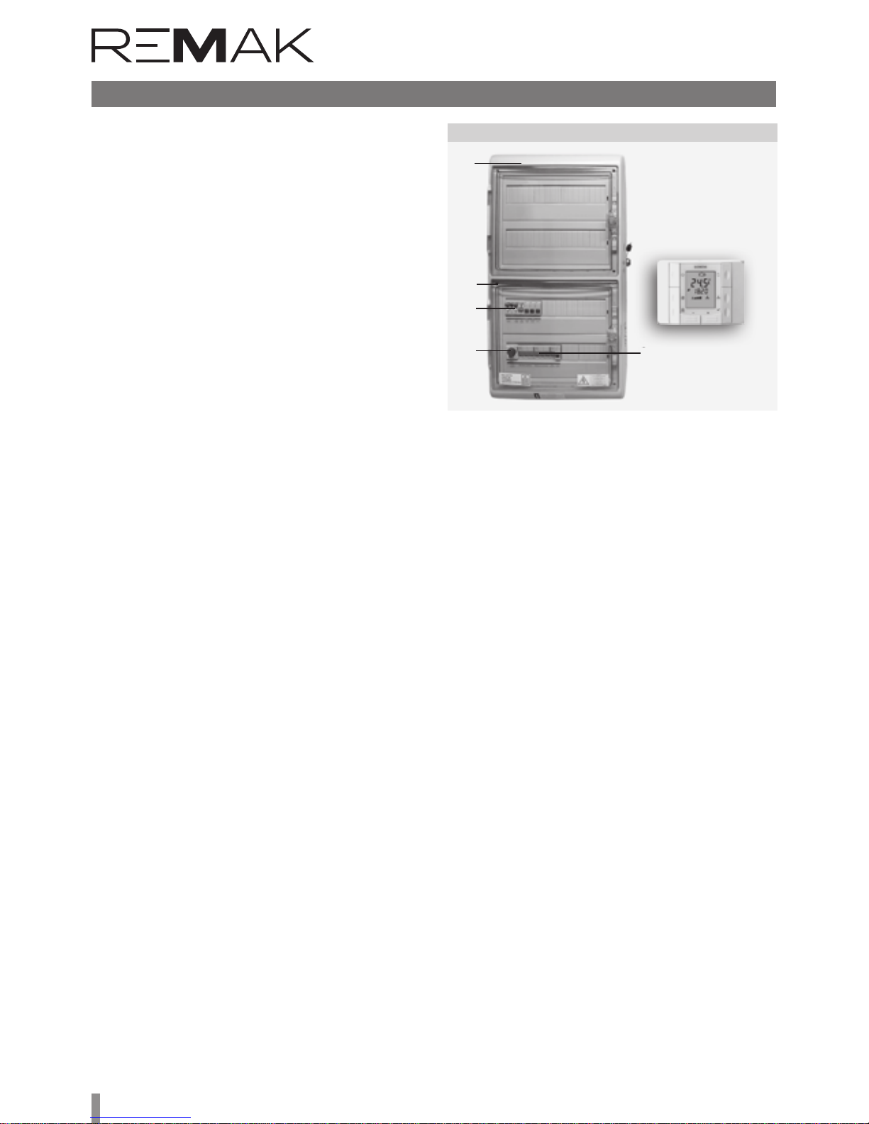
Figure 1 – VCS control unit design
Control unit box
Screws
Circuit breakers
Disconnecter
Master switch
HMI-SG controller
For local control, the HMI-SG POL822/60 hand controller
can be used. e control unit allows up to 8 basic control
sequences to be used depending on the air-handling unit
confi guration. e order of some sequences can be changed
(e.g. heating-mixing damper or cooling-fan cooling).
e heat pump or electric a er-heater can be separated from
basic sequences in the so-called extra sequences.
If this is the case, another sensor must be used in the air inlet,
and a special set-point must be set for this type of control.
is feature can only be used a er prior consultation with the
manufacturer. ese units are delivered adapted to individual
applications so they will provide exactly those features needed
for the operation of a specifi c air-handling device.
Control
Local control
e basic VCS controllers are devices (manual controllers
with bus connection) for so-called local control of the control
unit (see fi g. 2):
a) Room controller - HMI-SG (POL822/60)
b) Comfortable universal alphanumeric driver
- HMI-DM nebo HMI-TM
Note: For details, see controllers instructions part of the
manual.
Distant control
In addition to local VCS controllers, so-called remote control
can be used. For this control, you need to connect VCS to LAN,
WAN or Internet (For production, the control unit must be
confi gured/ordered with the required functionality).
a) HMI@WEB - You can use the HMI @ WEB controller via
the web interface. e controller fully complies with the local
HMI-DM and TM controls.
b) Mobile app (see fig. 3) - You can use simple touch
application for smartphones or tablets with Google Android
(v. 4.0.3 and higher).
c) SCADA web interface
Monitoring and operation using the device’s technological
scheme with operating parameters, respectively using the
tabular interface of an internet browser on a PC. For details,
refer to page 58.

3
Control units VCS
Figure 2 – HMI-SG (-DM, -TM) controllers
Figure 3 – Mobile application
HMI-SG
Figure 4 – VCS control unit internal structure
Other controls (technological)
For basic control (triggering, mode switching)
from a technology or a very simple manual button / switch
control, you can use "Other Controls". External control via one
or two non-voltage contacts.
Control from parent system
When integrating HVAC with the VCS control unit into complex
building management systems (BMS), it is also possible to
connect to these systems. Subsequently, it is possible to
control and monitor the HVAC through them. e ModBus,
LON, and BacNet standards can be used.
The different types of control must be designed when
designing (confi guring) VCS into the project and especially in
production - the usability of remote control and connectivity
to the BMS are dependent on the use of the corresponding
controller.
Detailed descriptions of all controller types, control and their
use - see separate sections / chapters of this manual.
HMI-TM
Control
HMI-DM
Power Part
e power part, like the control part, is always "tailored" for
a specifi c air-handling unit.
Connecting terminals
Connecting terminals
Controller
Siemens Climatix

4
Design
Table 2 – List of connecting cables (example)
Cable No.
Figure 7 – Component wiring (example)
Figure 6 – Summary of connected components (example)
Boxes
Indoor VCS control units are built into plastic or sheet metal
cabinets with front transparent doors under which controls
are located. e permissible ambient temperature is 0 ° C
to + 40 ° C.
VCS in exterior design are built into sheet metal cabinets
with full front doors under which controls are located. In
the confi guration so ware we can design: range of average
temperatures -40 ° C to 35 ° C, cabinet mounting (hanging /
stand), door design (le / right), lighting, service drawer (select
according to customer's destination).
A space of minimum 15 cm must be le on each side of the
box to allow access for cooling air and for changing the fi lter
which is fi tted in front of the fan.
As a standard, we provide a door lock and a box for storing
unit documents. Depending on the particular confi guration of
the control unit, these enclosure dimensions are used (Table
1). e electrical enclosure of the plastic case corresponds to
IP 65 with the door closed and IP 40 when the door is open.
e electrical cabinet cover is IP 55 or IP 66 (depending on
enclosure type) when the door is closed and IP 20 when the
door is open. e metal enclosure with additional ventilation
is IP54 with the door closed and IP 20 with the door open.
The VCS control units can be mounted directly on the
Flammability Levels A and B according to EN 13501-1.
Additionally, the VCS control unit can be manufactured in an
integrated design as part of the ventilation unit section. One
of the options is a built-in section for assembled VZTs, which
includes adjustments for the environment. is section is used
when designing VZT with IP44 protection as well
for outdoor units (with heating or cooling of the control unit).
Table 1 – box dimensions in mm
If needed, the boxes, sized 2000 × 800 × 400 mm and 2000 × 1000 × 400 mm, can be
fi tted with a ventilation set – a fan and a louver in opposite corners.
VCS
ACX36/RMK
Figure 5 – Installation in the XP unit section
Design
e control system design is based on the selection of required features and on its internal confi guration. e design
is performed automatically using the algorithm integrated
into the design so ware also used for the air-handling unit
design. e design output provides an exact specifi cation of
the control unit, including the following individualised lists for
a specifi c device:
n Summary of connected components
n Wiring diagrams of all components
n List of all recommended cables for the connection of all
components (the cables must always be used in accordance with the electrical equipment project documentation).
Version Height Width Depth Usual application
Plastic 610 340 160
Vento, FP, some XP (single-speed)
Plastic 610 448 160
Vento, FP, some XP (single-speed)
Plastic 842 448 160
Vento, FP, some XP (single-speed)
Sheet-steel 800 550 250 XP, sophisticated Vento assemblies
Sheet-steel 1200 750 300 XP
Sheet-steel 1600 750 300 XP
Sheet-steel 2000 800 400 XP
Sheet-steel 2000 1000 400 XP
(Recommended) cable type Power Supply Cable length Note
a) AeroMaster XP b) CAKE

5
Control units VCS
Figure 8 – Example of access to the unit
max. 700 m
HMI-SG
Documentation
Control Unit Designation
e control unit designation is always created by a unique
code (generated by the AeroCAD design program for the
control unit calculation and design), which is only included
in the accompanying technical documentation (not on the
control unit), and by the serial number (for communication
with the manufacturer).
Documentation
VCS control systems can be installed and used only in accordance with the delivered documentation.
Documentation List
n Product Installation and Operating Instructions
n Control system confi guration (summary of connected
components), terminal diagram and list of recommended cables – device printout from the AeroCAD design
program
Additional – General Documentation
e system or device documentation also includes the operating and inspection documentation kept during the device
service life and the Service Regulations, for which the user
is responsible.
Service Regulations
Before putting the air-handling device into permanent operation, the device user in collaboration with the designer, or the
supplier, must issue service regulations in accordance with
local regulations.
We recommend including the following in these service
regulations:
n Air-handling device assembly confi guration, its intend-
ed use and a description of its operation in all operating
modes
n Description of all safety and protective elements and
their functions
n Summary of the health protection principles, safety and
operating rules to be observed when operating the airhandling equipment
n List of requirements for operating staff qualifi cations and
training, nomenclature list of personnel authorized to operate the air-handling device
n Detailed emergency and accident instructions to be fol-
lowed by the operating staff
n Operating particularities in diff erent climatic conditions
(e.g. summer or winter operation)
n Inspection, checking and maintenance schedule, includ-
ing a list of checking steps, and their recording
Documentation Availability
e documentation delivered with the control system (original)
and operating documentation must be permanently available
for the operating and service staff and stored near the airhandling equipment. e Installation and Operating Instructions
are also available at the website: https://www.remak.eu
Warning
e manufacturer reserves the right to make changes and
amend the documentation due to technical innovations and
changes to legislation without prior notice. Information on
changes and updates are always available at the website
https://www.remak.eu
Safety Measures
n VCS control units are manufactured in accordance with
valid regulations and technical standards.
n VCS control units must be installed and used only in ac-
cordance with this documentation.
n Any damage caused by improper use contrary to this
documentation is the responsibility of the subject who
failed to observe the instructions included in this documentation.
n When handling, installing, wiring, commissioning, repair-
ing or servicing the air-handling units, it is necessary to
observe valid safety rules, standards and generally recognized technical rules.
n In particular, it is necessary to use suitable tools and per-
sonal protective work aids (e.g. gloves) because of sharp
edges and corners, respectively voltage, when performing any handling, installing, dismounting, repairing or
checking.
n Any changes or modifi cations to individual components
of the VCS control unit which could aff ect its safe and
proper functioning are forbidden.
n e air-handling equipment confi guration and documen-
tation must not be changed without the prior consent of
the manufacturer.
n e VCS control units, including their individual
parts, are not intended, due to their concept, for direct sale to end customers. Each installation must be
performed in accordance with a professional project created by a qualifi ed designer who is responsible for the
proper selection of equipment concerning its suitability
for the given application.
n All connections of the equipment, including the VCS con-
trol unit, to the power mains must be performed in accordance with applicable local wiring standards and regulations.
n Wiring installation, commissioning, maintenance and re-
pairs may only be performed by a specialized assembly
company, respectively an authorized person duly qualifi ed in accordance with generally valid regulations.
n Before installing and using the air-handling units, it
is necessary to familiarize yourself with and observe
the directions and recommendations included in the
following chapters.
HMI-SG

6
Conditions for Handling
e device can only be commissioned, operated and serviced
by qualified personnel.
n e VCS control unit can only be operated by person-
nel provably trained and warned about possible dangers
(by the manufacturer or authorized representative of the
manufacturer) in accordance with the applicable Service
Regulations for the air-handling unit.
n It is forbidden to remove, bypass or disconnect the safe-
ty equipment, safety functions and guards.
n Only air-handling components in perfect condition can be
used. Failures affecting the equipment safety must be removed immediately.
n All safety measures against electrical accidents must be
strictly observed. Any action resulting in restriction, even
temporary, of the safety and protection functions must
be avoided.
n It is strictly forbidden to remove safety guards, casings
or other safeguards, operate the equipment or its components if the safeguards are disabled or restricted.
n Any action resulting in restriction of the prescribed insu-
lation of the safety voltage must be avoided.
n When changing fuses, it is necessary to ensure the non-
voltage state of the control unit and use only the specified fuses and protection elements.
n It is necessary to eliminate electromagnetic interference
and the harmful effects of over-voltage on the signal,
control and power cables, which could unintentionally initiate dangerous actions and functions or cause destruction of the electronic parts in individual components.
n Never work on the connected equipment under voltage!
Before starting work on the air-handling unit, switch off
and lock the master switch to disconnect the supply voltage. Use protective and work aids in accordance with
the Service Regulations and standards applicable in the
country where the unit is installed.
n If individual technical assemblies of the air-handling unit
are equipped with service switches, and if allowed by the
Service Regulations, installation conditions and characteristics, then such assembly (e.g. heater, fan, etc.) can
be disconnected by switching off and locking the corresponding service switch.
n Never use abrasive cleaners, cleaners unsuitable for plas-
tics or acid or alkaline solutions to clean to unit.
n Avoid splashing water, impacts and vibrations.
Each air-handling equipment component must always
be installed in accordance with the appropriate installation instructions.
e manufacturer recommends fully ensuring the flawless condition and functioning of all protective elements
and equipment. Aer failures, such as short circuits, have
been removed, check the functionality of the automatic
circuit breakers and protective elements, and verify the
condition of the protective wiring interconnection and
grounding.
To ensure safe operation, it is necessary to verify the conditions of the water heating/cooling pumps – perform
manual pump turning and set the output curve (over-design impairs the control quality).
Warning: If the remote control is used (including automatic
schedule program), safety access must be ensured for each
physical interference or entry into the air-handling unit (inspection, maintenance or repair) – i.e. disconnect the power supply
by turning off the switch – avoid remote initiation of the unit
by other users when work is being performed on the unit.
Transport and Storage
Before Installation
VCS control units are packed in cardboard boxes or installed
in the corresponding air-handling unit section, if they are
integrated into the air-handling unit. Measures for handling
fragile goods must be taken when handling the unit.
e units must be stored in rooms complying with the following conditions:
n Maximum relative air humidity must not exceed 85%,
without water condensation
n Ambient temperature between –25°C and +60°C
Dust, water, caustics, corrosive agents or other materials
negatively affecting the structure or the unit’s components
(causing degradation of plastic parts and insulation) must
not enter the unit.
Installation and Location
e VCS control unit location must provide good access for
the operating personnel and easy connection of the cables.
e installation site must be flat without rough spots.
When planning the air-handling unit location, it is necessary to
keep sufficient space for maintenance, service and operating.
Check the completeness and intactness of the delivery in accordance with the bill of delivery before installation.
ese control units are designed for normal (indoor, dustless,
dry, non-explosive) environments. ey can be mounted on
A and B combustibility grade materials in accordance with
EN 13501-1.
Permissible ambient temperature: +0 °C to +40 °C (24h average must not exceed +35 °C)
e VCS control units in the switchboard boxes are mounted
in the vertical position directly on the wall. e KAEDRA plastic
switchboard box can also be partially embedded under plaster.
e VCS unit installed in steel switchboard boxes can also be
placed directly on the floor. e cables can be run along cable
trenches, cable trays or under plaster.
e power cables are connected from below.
We recommend the wall-mounted units be fixed to the wall
using dowels and screws suitable for the wall structure.
Manipulace, transport, umístění
n e air-handling equipment can only be operated in ac-
cordance with the applicable Service Regulations. e
operating staff must comply with the requirements included in the Service Regulations, respectively with the
manufacturer's requirements (authorisation for some
service activities).
n To avoid unintentional unit start-up, the master switch
must be switched off and locked when repairing the
VCS unit.

7
Control units VCS
Note: As appropriate, the above-mentioned instructions apply also for control units integrated into the air-handling unit
while observing the control unit installation and operating
instructions delivered with the air-handling unit.
Check the completeness and intactness of the delivery in accordance with the bill of delivery before installation.
Commissioning
Fitting and Wiring Check
A careful check and verification of the wiring of all control
system components in accordance with the attached unit
wiring diagram must be performed before the first start-up.
e system cannot be connected to the power supply until
these checks have been performed.
First of all, it is necessary to check the presence, locations and
connections of the temperature sensors, fan thermo-contacts
and heaters in accordance with the M&C project. Further, the
connections of all error inputs must be checked.
It is also essential to check the fans, electric heaters, heat exchangers, filters and other parts of the connected air-handling
unit for correct fitting in accordance with the air-handling
accompanying documentation.
e above-mentioned checks must include a functionality
check of each component.
Special attention must be paid to the check of the conductive interconnection of all parts of the air-handling unit and
associated devices.
Conditions for Connection
e connections must be performed in accordance with the
applicable local wiring standards and regulations. Before putting the unit into operation, an initial wiring inspection must
be performed in accordance with the national regulations.
Settings
e VCS control unit has been manufactured according to the
customer’s requirements (the project), and the basic parameters have been pre-set so that the unit is ready for operation.
With these settings, the control unit will start and begin the
control for the pre-set parameters providing the connection
of the unit has been performed correctly.
However, the professionals performing the unit commissioning
must always check or adapt the air-handling unit’s operating
parameters to the specific design and behaviour of the control
system and operating or local conditions.
It is especially necessary to pay attention to the control
constants and parameter, various correction values,
temperature modes and time schedules, optional modes
and functions.
e data points are accessible through the HMI control panel.
Setting the user access levels is an important part of the
settings procedure.
e default factory settings must be re-set according to the
user and service company needs.
e Access passwords are the basic pre-set parameters which
need to be reset when commissioning the unit, see the chapter
Control (HMI-SG).
Additional Settings:
n To optimize the interaction between the control unit and
peripheral devices, it is necessary to set, using the HMISG controller (see the List of Data Points in the section
Settings – Control Signal Characteristic), corresponding values of the analogue signals for heating, cooling,
heat recovery and gas heating, optional from 0–10 V and
2–10 V (pre-set).
e values 2–10V are suitable for REMAK or Belimo actuators.
Room temperature Measuring Point Selection
n Up to two room temperature sensors can be installed in
the air-conditioned room (HMI-SG controller with an integrated temperature sensor plus one additional temperature sensor, or two HMI-SG controllers with integrated
temperature sensors). e final room temperature value for the control can be set as the minimum, maximum
or average of both sensors (see the List of Data Points -
Temperature Measuring Point Selection).
Selection of the specific point for adjusting or measuring the
temperature value entering the control process results in more
accurate setting of the room temperature.
Warning
e device parameters are structured and made available
to users in accordance with their user roles (access levels).
ese roles must be assigned to the users according to their
expertise and responsibility for device operation.
Basic Application Parameterization
n Default and common operation parameterization is de-
scribed in the chapter Control (see particular controller).
General Overview of Parameters
For a general overview of parameters available in the menu
and access authorization of users, refer to the chapter VCS
– Parameter Overview and Default Factory Settings. For the
menu with HMI controller parameters and default values, refer
to the chapter Control (HMI-SG).
Important Notes
Correct assembly, installation, commissioning and proper
control are the essential conditions for flawless and safe
operation of the control unit. e components connected to
the control unit must correspond with the specification in the
control unit documentation.
e procedures specified by the manufacturer in the unit
documentation and the Service Regulations measures must
be observed throughout the unit service life.
Commissioning

8
Location of Control System Sensors
Inlet Air Temperature Sensor (NS 120)
Control and anti–freeze sensors must always be situated
behind the heater, respectively cooler – to measure the supply air temperature. ey must not be situated in the room.
VO antifreeze protection sensor (NS 130R)
e return water temperature sensor must be situated in
the return water line from the water heater so that it will be
sufficiently bathed in water. e heating water circuit must
ensure all the required functions for the water heater control
and safety when the unit is shut down (filling the system
with antifreeze mixture) as specified in the air-handling
device project documentation. A capillary tube can be used
as additional antifreeze protection. If it is not installed on the
air-handling unit by the manufacturer, the capillary tube must
be run (meandering way) through the entire cross-section of
the water heater’s rear side.
Outdoor air temperature sensor (NS120)
Ideally, it should be situated in the outside environment – only
then are the control system’s functions ensured even in the
STOP mode or immediately aer unit start-up (e.g. moderate
pre-heating of the exchanger based on the actual outside
temperature, etc.).
If the sensor is situated in the fresh air inlet duct inside the
building, the measured temperature is only correct when the
fans are switched on (air flows) and the starting conditions
are negatively affected – which can endanger the air-handling
device’s safety and even result in the water heat exchanger
breaking down.
Outdoor Temperature Sensor
– installed outside (NS110A)
e sensor (as with any thermometer) must be installed
so that objective outdoor temperature measurement will
be achieved. It must be protected against negative effects
like sunshine, rainfall, frost deposits, e.g. situating it under a
building’s roof, using outdoor VZT roofs, situating it in the inlet
louvers, inlet ducts or separate covering roof.
Room Temperature Sensors
Optionally, a room (NS100), duct (NS120) or HMI-SG controller integrated sensor can be used by the designer.
Commissioning
EO Pre-Heating Control Temperature Sensor (NS 120)
To ensure correct control, the sensor must be situated behind
the electric pre–heater (EO) – before other temperature
adjusting components.
Flue Gas Temperature Sensor
e Pt 100 sensor is used to measure the flue gas temperature. e sensor must be situated in a representative place
within the flue gas installation.
Inlet Air Humidity Sensor
is is a duct sensor which must always be situated in an inlet
branch aer the air-handling unit. e selected position must
be representative enough for the measured value. It must not
be situated in the room.
Room Humidity Sensor
Optionally, a room or duct sensor can be used by the designer.
n e room sensor must be situated in the room in a "rep-
resentative" place so that it will not be influenced by local
effects (windows, doors, etc.)
n e duct sensor must be situated in the outlet duct from
the room – the advantage here is that the mean humidity of
the room outlet air is measured.
TH 167 Gas Heating Safety ermostat
e sensor must be situated before the gas heater section
behind the fan section. e thermostat must be situated so
that it will start the fans to protect the air-handling components situated in front of the gas heater chamber if back air
flow occurs.
Air Quality Sensor – CO2 (VOC, CO)
e air quality sensors are placed in the outlet air duct or in
the "representative" spots, thus ensuring objective air quality
value measuring.
Connection of the fan frequency inverters,
heat exchanger to the Modbus bus
Safety Conditions
n Properly carried out transport, storage, installation, com-
missioning and careful handling is the main condition for
correct and trouble-free operation.
n Protection, switching, wire routing and grounding must
fully comply with the local regulations applicable for wiring.
n e 230/400 V AC power wiring must be strictly separated
from the signal wiring (e.g. 24 V AC SELV)!
Figure 9 – Room sensor installation
• e room sensor or HMI-SG controller with integrated room
sensor must be situated in a spot "representing" the room temperature, and they must not be affected by local effects (heaters,
windows, vertical temperature distribution in the room, etc.)
• e duct sensor must be situated in the room outlet duct
– the advantage in this is that the average temperature of the
air flowing from the room is measured without being affected
by local effects (and it is hidden).
Heat Exchanger's Antifreeze Protection Sensor
(NS 130R)
e sensor must be situated in the outlet air duct behind the
heat exchanger.
9
Control units VCS
Control and Protection Functions
Wiring
n A shielded conductor must be used for the Modbus bus
connection. e maximum conductor length depends on
the communication speed. A maximum length of approx.
1000 m is recommended for the baud rate of 9600 Bd. e
recommended conductors are included in the documentation
created by the AeroCAD design program.
n e controller is connected to two terminals marked A+
and B- and to the REF signal detection reference voltage
terminal, which must always be interconnected with other
participants on the bus.
n To ensure correct functioning of the bus, the fi rst and last
device on the bus must be fi tted with a terminal resistor. e
fi rst device, i.e. the master controller, terminal resistor setting
is performed using the so ware (ensured by REMAK in the
factory). e last device terminal resistor setting is performed
on the last frequency inverter in the line connection. Refer to
the Modbus bus wiring diagram. e setting procedure of
the last terminal resistor is described in the documentation
for a corresponding frequency inverter. A 120 Ohm resistor
connected between the communication can also be used to
terminate the wiring.
Fan Failure Detection
n To detect any fan failure, the motor thermo-contact and
diff erential pressure sensor are connected to the frequency
inverter inputs. e information provided by these elements
is transmitted through the Modbus communication line to the
control system, where it is processed.
Modbus RTU Communication Settings
n Each frequency inverter connected to the bus must be
assigned a unique address as defi ned in the control system
data points.
Pre-set Frequency Inverter Addresses – ModBus:
Inlet Fan
Inlet fan address =1
Backup or twin fan address =2
Backup twin fan 1 address =3
Backup twin fan 2 address =4
Outlet fan
Outlet fan address =5
Backup or twin fan address =6
Backup twin fan 1 address =7
Backup twin fan 2 address =8
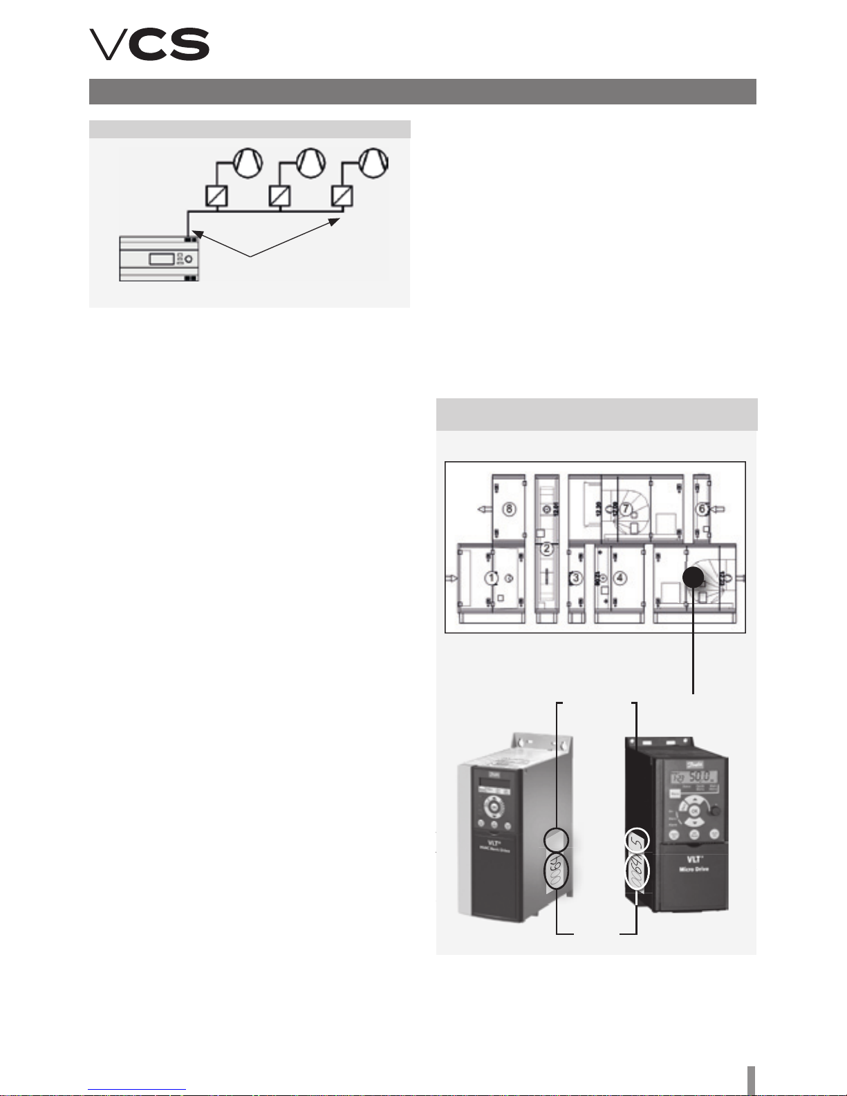
Figure 10 – Inverter connection to the Modbus RTU
Figure 11 – Inverter association with a corresponding
section
terminal
resistor
RS485
FM1
Master
controller
FM2 FM3
Warning
e frequency inverter association cannot be exchanged
between diff erent sections! For information about frequency
inverter association with a corresponding section, refer to
the fi gure.
Auxiliary Fan
Auxiliary fan address =9
Twin fan address =10
Rotary Heat Regenerator
RHR motor address =11
n e data points of all frequency inverters for communica-
tion with the Modbus bus must be set in accordance with the
VCS control unit:
• Baud rate (9600 Bd – pre-set)
• Parity (none – pre-set)
• Number of stop bits (2 stop bits – pre-set)
• Response time limit
• Number of data bits (as standard, 8 bits – pre-set)
All data points for the used frequency inverters are available
on our website: www.remak.eu
Corresponding
section number
Order
number
5
0064 / 5
00
64 / 5
64 / 5
0064 / 5

10
Main Control Feature and
Protection Description
Using the appropriate sensors, the VCS control unit can
provide comprehensive protection of the air-handling unit,
such as active antifreeze protection, fan state monitoring,
filter fouling or over-temperature detection of the required
temperature. Any deviations from the defined states or
parameters are monitored and signalled and simultaneously,
safety features are activated.
Depending on the failure consequence, the following happens:
n e failure is only signalled and safety features are automati-
cally activated. Once the failure has ceased, the unit will return
to the standard mode without interference from the operator.
n If a serious failure occurs, the unit will be switched to
the STOP mode, and it can only be restarted after the
failure has been removed and the operator's interference.
e VCS control unit system enables the air-handling unit
behaviour (fan action) to be set when fire is detected
(external failure, inlet or outlet air high temperature).
The settings can be as follows: the inlet or outlet fan is
activated, both fans are activated or both fans are stopped
(air-handling unit shutdown). e control unit is switched to
the fire mode. e settings can be performed using the HMI
controller in the List of Data Points, section Checks, System
and Network Settings – Fire Alarm.
Heating Control
Control is based on the required temperature, i.e. the selected
temperature mode and data from the supply air temperature
sensors, outdoor temperature and the water heat exchanger
return water temperature. Control can be affected by correction values, maximum and minimum limits or antifreeze
protection.
Water heating
It is controlled by the SUMX mixing set actuator using a 0–10V
continuous control signal (working range of 2–10V).
Heating Mixing Set Pump Control
e mixing set pump is controlled depending on the outdoor
temperature value and valve position (required heater output).
n If the air-handling unit is in the STOP and Run mode, the
pump is switched on when the outdoor temperature drops
below 5°C and switched off when the outdoor temperature
rises above 6°C. In this case, the pump is stopped without
any run-down.
n If the air-handling unit is in the Run mode, the pump is
controlled by the valve actuator control algorithm. e pump
is switched on when the request for the valve opening is
higher than 5%.
n If the pump has not been used for 168 hours, it will be
switched on and turned for 60 seconds.
n Failures (electrical) of the pump are sensed by the pump
circuit breaker’s auxiliary contact even in the STOP mode.
Water Heater Antifreeze Protection Operation
e VCS control unit uses so-called active antifreeze protection. It uses a three-stage concept.
Antifreeze Protection Features:
Control and Protection Functions
Note: is chapter describes only the basic control functions
– the detailed design, respectively compatibility, of the entire
device is ensured by the configuration performed using the
AeroCAD design soware. For more detailed information,
contact the manufacture, REMAK a.s.
Main Control Features
e VCS control unit enables automatic control of the following basic functions for air temperature adjustment:
n Heating
n Cooling
n Mixing
n Recuperation (Heat Recovery)
n Dehumidification
n PID controllers with pre-set control constants are as-
signed for all the above-mentioned functions. Basic settings
of parameters are performed in the factory. e parameters
can be changed using the HMI controller in the List of Data
Points menu, item Control Constants.
n A check, respectively optimization, of the unit settings must
always be performed when commissioning the unit.
n Control ensures energy-saving operation. Cascade tem-
perature control – room temperature control or supply air
temperature control.
n e required temperature for the air-conditioned room
can be set by selecting one of two temperature modes. Each
mode has two pre-set temperature values to maintain the
required temperature (an upper limit for heating and a lower
limit for cooling). ese values can be changed using the HMI
controller in the List of Data Points, section Settings – Temperature Modes.
n First, the control algorithm will start to control the functions
which don't require energy, i.e. heat-recovery and mixing (depending on the user option). If this is not enough to maintain
the required parameters or these features are not included in
the air-handling unit, heating and cooling functions will be applied. If the heating or cooling control is not effective enough,
an air output control will be added (heating/cooling-dependent
fan speed compensation – user option). is control does not
allow heating and cooling to be used at the same time, only
one control sequence can be used at a time. is does not
apply for special control application with controlled humidification where a cooler can be used for dehumidification and a
heater for aer-heating to the required temperature.
Heat pump, water and electric heater or gas heater functions
can be connected to the heating control sequence. Heat pump,
water cooler and condenser unit functions can be connected
to the cooling control sequence.
Temperature Correction and Limitation
The control unit enables adjustment and settings of the
restricting limits for maximum and minimum supply air
temperatures. In addition, it is possible to set the supply air
and room temperature limits, respectively other correction or
comfort options (e.g. set-point value compensation or heating/cooling-dependent fan speed compensation).
Control and Protection Functions

11
Control units VCS
n Switching of the unit to the STOP mode
n Switching off of the fans
n Closing of the dampers
n Freezing danger signalling
n Mixing set control
n Pump starting
n If the air-handling unit is in the Run mode, then antifreeze
protection is activated when the outdoor temperature drops
below 10 °C (factory settings) and the water heat exchanger
return water temperature drops below 15 °C (factory settings). e extent of the mixing valve opening depends on
the water heat exchanger’s return water temperature value.
Antifreeze protection will be deactivated when temperatures
rise above the limit parameters.
n If the air-handling unit is in the STOP - STAND-BY mode,
then antifreeze protection is activated when the outdoor
temperature drops below 10 °C (factory settings) and the
water heat exchanger’s return water temperature drops
below 30 °C (factory settings). e extent of the mixing valve
opening depends on the water heat exchanger’s return water
temperature value. Antifreeze protection will be deactivated
when temperatures rise above the limit parameters.
n e control unit continuously monitors the water heat
exchanger’s return water temperature. If the temperature is
still falling and drops below 8°C (factory settings), the following
protection actions will be immediately taken regardless of the
outdoor temperature:
n e air-handling unit will be shut down, the dampers will
be closed, the fans will be switched off and the failure alarm
will be activated.
n e mixing valve will be opened depending on the water
temperature, and the circulation pump will be switched on.
n e above-mentioned state will last until the operator
checks the air-handling system or removes the failure cause
and confirms the air-handling system is free of failure and
resets the failure.
n e control unit simultaneously monitors the supply air
temperature in the Run mode. If the supply air temperature
drops below 6 °C (factory settings), the following protection
actions will be immediately taken regardless of the outdoor
temperature:
n e air-handling unit will be shut down, the dampers will
be closed, the fans will be switched off and the failure alarm
will be activated.
n e mixing valve will be opened depending on the water
temperature, and the circulation pump will be switched on.
Pre-Start Unit Pre-Heating Functions
n To avoid false freezing danger assessment in winter or
during transition seasons, especially when the air-handling
unit is being started, the control unit features a heating
circuit pre-heating.
n Pre-heating is dependent on the outdoor temperature
value. If the outdoor temperature is higher than 10 °C, the
value of the valve opening will be 0 %, and pre-heating will
not be activated.
Pre-heating will be activated when the outdoor temperature
drops below 10 °C. e mixing set valve will be forced to open
to the value which is derived from the outdoor temperature
(factory settings: +10 °C = +10 %, -10 °C = 100 %) for 120
Control and Protection Functions
seconds. Once this time has elapsed, the valve will be closed,
"ramped down", until the mixing set control signal for heating is reached.
n If the air-handling unit is restarted within 5 minutes of the
moment the air-handling unit was shut down, pre-heating
will not be activated.
n Antifreeze protection setting parameters can be accessed
through the HMI controller in the List of Data Points menu,
sections Parameters and Control Constants.
Electric Heating
Electric heating can be controlled using the following options:
n Switching of the full EO, EOS heater output
n Sequential switching of the EOSX electric heater’s indi-
vidual sections
n Sequential switching of the EO heaters
n Control of the EOS electric heaters using a PV valve (up
to 45 kW)
Electric heater protection
n If electric heater overheating (failure) is signalled (the
temperature inside the heater exceeds +80 °C) by opening
the emergency thermostat contacts in the heater, this signal
is interpreted by the control unit.
n Electric heater control in the REMAK unit is doubled – the
heater thermostat failure signal is simultaneously sent to the
controller and auxiliary module.
n e controller will interpret the failure signal and perform
appropriate safety functions; first, the control signal for
electric heating is blocked and then the heater contactor is
disconnected.
n e auxiliary safety module will mechanically disconnect
the EO/S/X circuit breaker (i.e. it will trip the under-voltage
trigger of the circuit breaker).
At the same time, control logic will ensure safe cooling of the
heater when the air-handling unit is being shut down – transition to the STOP mode. e controller will ensure run-down of
the fans (optional) so that the heating core is cooled.
Gas heating
e gas heater is controlled using a burner output controller
and a bypass damper (if the section is equipped with a BP
damper). The required heating temperature is controlled
depending on the required temperature (selected mode) and
the readings from the inlet temperature, outdoor temperature
and flue gas temperature sensors.
Gas Burner Output Control
n Single-stage ON/OFF control
n Two-stage control (two output stages)
n Modular (three-point), step-less control of the entire burner
output range
Burner lighting is contingent on the fan operation.
At a 5 % request for heating, the 1st burner output stage is
switched on. e minimum pre-set running time of this stage
is 150 seconds. If the required temperature is not reached,
the 2nd stage will be switched on at 70 % of the request for
heating (two-stage output control). e second output stage
is not restricted to the minimum running time, and will be
switched off at 40 % of the request for heating.

12
Control and Protection Functions
Further re-lighting of the burner is possible once the protection time of 150 seconds has elapsed. Modular control of
the burner is step-less based on the actual requirement (set
point) within the Min to Max output range of the gas burner.
e bypass damper (if included in the section) is controlled by
a 0-10V signal (the operating range is 2–10 V depending on
the required flue gas temperature (160 °C pre-set). e regulating damper position controls the air flow coming through the
gas section and bypass section so that a constant flue gas
temperature is maintained. Accordingly:
n when T
flue gas
> T
flue gas required
the bypass damper closes
(closed = 0 V)
n when T
flue gas
< T
flue gas required
the bypass damper opens
(open = 10 V)
Protection and Safety Functions:
e control unit ensures fan run-down to cool down the gas sections (the pre-set run-out time is 180 s). e gas section temperature is monitored by the ESD3J triple safety thermostat,
which ensures the following protection and safety functions:
n If the temperature exceeds 50 °C, the fans will be switched
on, even if in the STOP mode.
n If the temperature exceeds 80 °C in the Run mode, the
burner will be stopped, the fans switched to the run-down
mode and then the unit STOPPED; if the temperature exceeds
110°C, the burner will be disconnected from the supply voltage. If back air draw (chimney effect) occurs during the STOP
mode and the air temperature in front of the gas section rises
above 50 °C, the TH 167 thermostat will close and switch on
the fans, open the inlet and outlet dampers, and thus the gas
section will be cooled down.
n Fan malfunction – the unit is immediately switched to the
STOP mode without fan run-out (evaluated also during the
STOP mode)
Heating and Cooling using Heat Pump
Two general control options are available for heat pumps.
Control is not fixed to a specific heat pump type. e control
option selection depends on the designer’s consideration
and heat pump type. Two control contacts and an analogue
output are used for control.
Option A
e first digital contact is used to define the air temperature
adjustment type – cooling/heating. e second digital contact
is used to define the process activation – off/on. e analogue
output 0..10 V represents the proportion of the request for
heating or cooling.
Option B
e first digital contact is used to define the heating process
– heating off/heating on. e second digital contact is used to
define the cooling process – cooling off/cooling on.
Analogue output 0..10 V represents the proportion of the
request for heating or cooling.
e heat pump control is equipped with an outdoor temperature-dependent blocking. e blocking alert is only informative
and is not a failure state. e heat pump will be shut down if
the outdoor temperature is equal to or lower than the refer-
Cooling Control
All cooling sources can be disabled depending on the outdoor
temperature. Cooling is not disabled if the outdoor temperature is higher than the pre-set cooling enable temperature
(pre-set 12 °C).
Water Cooling
It is controlled the same way as water heating. e mixing
set pump is switched depending on the control signal for the
cooling valve. If the air-handling unit is in the Run mode, the
pump will be switched on when the control signal for the cooling valve is higher than 5% and switched off when the control
signal for the cooling valve is lower than 1%.
n Pump turning for 60 seconds is performed aer every 168
hours of pump inactivity..
Direct Cooling
Direct cooling is controlled by switching the condensing unit
output or by step-less control of the inverter condensing unit.
If a single-circuit condensing unit is used, it will be switched on
when 20 % of the control signal is required and switched off at
10 % (10 % hysteresis) of the control signal. If a double-circuit
condensing unit, respectively two single-circuit condensing
units are used, two stages will be switched. e first stage will
be switched on when 20% of the control signal is required and
switched off at 10% (10% hysteresis) of the control signal. e
second stage will be switched on when 70 % of the control
signal is required and switched off at 60 % (10 % hysteresis)
of the control signal. Frequent switching of the single-stage
condensing unit is eliminated by repeated cooling blocking
for a certain time depending on the setting.
To eliminate the simultaneous switching of both stages at
a sudden control signal increase, the timing (duration of the
first stage) is set.
Inverter Cooling Unit
It is controlled using the start enable signal and step-less
compressor output control signal. e minimum operating
time can also be set. e condensing unit will be switched on
when 20 % of the control signal is required and switched off at
10 % (10 % hysteresis) of the control signal. e unit compressor speed is controlled using a 0–10 V control signal.
ence temperature (see the Data Points). e heat pump will be
started if the outdoor temperature is higher than the reference
temperature (with hysteresis of 3 °C). Frequent switching of
the heat pump is eliminated by blocking of the cooling/heating
restart for 120 seconds. e minimum operating time of the
heat pump can also be set. When cooling/heating is required,
the heat pump will be switched on at 20% of the control signal
and switched off at 10% of the control signal (hysteresis of
10%). e low reference signal on the analogue output (0-10V)
can be set in a range from 0% to 50 % of the control signal
(pre-set 30 %, i.e. a 3-10 V control). e unit can be equipped
with a function blocking the air-handling unit operation when
defrosting the heat pump. e shut-off state of the air-handling
unit is indicated on controllers. Aer the heat pump defrosting
process has been completed, the air-handling unit operation
will automatically be resumed.
Furthermore, it is possible changing behaviour of different
control signals, e.g. AO signal inversion (see Data Points).

13
Control units VCS
Control and Protection Functions
Inverter Unit and Single-Stage Condensing Unit
Combination
When cooling is required, the inverter will be switched on
first and then the output will be raised to the maximum.
Consequently, the single-stage condensing unit is switched
on while the inverter output is lowered to 30 % of the control
signal. If the request for cooling is still rising, the inverter
output will be increased from 30 % up to the maximum level
of the control signal.
If the request for cooling is decreasing, the inverter output will
start to decrease and will be switched off at 0% of the control
signal. e single-stage condensing unit is still in operation.
In this phase of control, time blocking of the inverter is applied and simultaneously the single-stage condensing unit is
prevented from being switched off. If the request for cooling
is still decreasing once this time has elapsed, the inverter
will be switched on with a maximum control signal and the
single-stage condensing unit will be switched off. When the
single-stage condensing unit is switched off, the inverter
output will be at the maximum. en the inverter output is
reduced in accordance with the request. us step-less control
is ensured in the entire cooling capacity range.
Direct Evaporator Protection
is protection is ensured using the CAP 2M capillary thermostat, which disconnects the control signal in the event of ice
build-up on the evaporator. If two evaporators are used, each
of them will have its own thermostat.
Heat Recovery Control
Heat Recovery control of the rotary heat regenerator is ensured by step-less control using the heat exchanger frequency
inverter through the Modbus communication bus. e plate
heat exchanger, respectively plate heat exchanger bypass, is
controlled using a 0–10 V (2–10 V) continuous signal. 100%
of the step-less control signal equals 100 % heat recovery,
i.e. maximum speed of the rotary heat regenerator or closed
bypass of the plate heat exchanger. A digital output for twopoint control (ON/OFF) is another option – thus, for example,
the glycol circuit pump can be switched.
Heat Exchanger Antifreeze Protection
n Rotary heat regenerator protection is ensured using the
NS 120 temperature sensor situated in the outlet air duct
behind the heat exchanger. If the temperature drops below
the pre-set ice build-up threshold, the speed of the rotary
heat regenerator will be reduced. If the speed reduction is not
enough to de-freeze the heat exchanger, the heat exchanger
will be stopped. e heat exchanger speed reduction depends
on the PID controller’s constant setting.
n Similarly as the rotary heat regenerator, control of the plate
heat exchanger is ensured using the NS 120 temperature
sensor and bypass actuator control. If the temperature behind
the plate heat exchanger drops below the pre-set ice build-up
threshold, the bypass damper actuator will be activated and
the damper will stay open until the ice build-up melts from the
heat exchanger. A pressure loss sensor or a CAP 3M capillary
probe can also be used in some cases.
Protection of the plate heat exchangers without bypass can
be ensured by a fan speed reduction.
Plate heat exchanger
– air-handling unit run-out
In some cases, the run-out will be performed when the
air-handling unit is stopped. is will ensure drying of the
heat-exchanger and prevent the creation of conditions for
the growth of microorganism. Temperature and humidity
sequences are active during this run-out. This feature is
conditioned by previous operation of the heat recovery and the
outside air temperature. As default, this feature is switched off.
For the change in all values, refer to List of Data Points – Fans.
Mixing Damper Control
It is ensured by step-less control of the mixing damper actuators using a 0–10V (2–10V) continuous signal. e signal is
directly proportional to the air circulation, i.e. 100 % of the
signal corresponds to 100 % of the required air circulation
(0 % of fresh air).
e maximum level of air recirculation (when the fans are
running) is limited by the minimum (hygienic) request for
fresh air. If the device is in the STOP mode, the inlet and outlet
duct dampers are closed and the circulation damper is open.
Heat Recovery and Mixing Economy Control
If the temperature in the room (in the outlet duct) is lower
than the outdoor temperature and a request for cooling
simultaneously exists, the heat recovery and air recirculation
functions will be automatically switched on at the maximum
level to minimize the energy demand for cooling. is happens if the temperature difference reaches 3 °C (the room
temperature is lower than the outdoor temperature) while the
temperature in the room (in the outlet duct) is higher than the
required temperature and the difference between these two
temperatures is at least 2 °C.
Heat recovery and mixing functions will be switched off when
the outdoor temperature is lower or equal to the room (outlet
air) temperature, or the room (outlet air) temperature is higher
or equal to the required room temperature. Heat Exchanger
control function activation settings are described in the chapter Additional Operating Mode and Function Setting Options.
Heat Recovery and Mixing Control
at Air-Handling Unit Start-Up
e starting outdoor temperature and time are set for heat
recovery and mixing (see Data Points). If the outdoor temperature is lower than the pre-set value at the air-handling
unit start-up, the heat recovery and mixing functions will be
switched on at the maximum level.
Mixing Sequence Selection
e mixing sequence for heating control is optional – the preset sequence for heating is as follows: first, the mixing function
is applied and if the request for heating still increases, then the
heating function will be applied (pre-set). is sequence can be
changed according to user needs, see the chapter Additional
Operating Mode and Function Setting Options.
Humidity Control
e control unit evaluates the control signal for humidification
or dehumidification depending on the room and inlet humidity
sensors and the required humidity selected by the user.

14
Control and Protection Functions
Humidification
Humidification control can be ensured by two methods.
Depending on the technology used, control for the required
humidity can be performed by the VCS control unit or by an
autonomous control (e.g., integrated into the humidifier).
In the first case, humidity control is ensured by the VCS control
unit. Settings of humidity set-points and control parameters
are included in the VCS control unit. e same applies for
dehumidification. us, full accord of dehumidification and
humidification control is ensured and unsuitable settings of
set-points cannot be made. Furthermore, all the necessary
parameters and information can be found in the control
unit controllers. e control unit sends the start command,
the request for humidification output to the humidifier, and
monitors humidifier failures.
If autonomous control is used, the control unit sends information on the air-handling unit operation to the humidifier.
In this case, control for the desired humidity is fully ensured
autonomously by a specific humidifier. e control unit has
no information about the state or output of the humidifier.
Dehumidification
Air dehumidification is ensured by water or direct cooling.
In case of dehumidification, aer-heating is ensured by the
heater, which is situated aer the cooler. e control unit evaluates the control signal for the air cooler and heater depending
on the room sensors and the required humidity selected by
the user. e humidity in the room can be set from 20% to
95%. If the air-handling unit is equipped with a water cooler or
a condensing unit with an inverter, the humidification process
can be controlled using 0–10 V (2–10 V) step-less control. If
the air-handling unit is equipped with a one-stage or a twosage condensing unit, the humidification process is controlled
using step control. When cooling is active due to a request for
dehumidification, air aer-heating is allowed (exceptionally)
using the heater situated aer the cooler.
If the request for heating is increased above 90 %, the request
for dehumidification cooling is gradually reduced until the
required inlet air temperature, respectively zero value of the
request for cooling (at 100 % request for heating), is achieved
– temperature control is prioritised to humidification.
Auxiliary Control Functions
Pre-heating function
Pre-heating is switched ON/OFF depending on the pre-set
outdoor temperature value (pre-set 5 °C).
e electric pre-heater (EO) is switched using a contactor. It
is controlled according to the pre-set (required) temperature
and compared with the temperature behind the preheater
(measured by the NS 120 sensor). If the air-handling unit is
switched off when the EO pre-heater is active, run-down of
the fans will be performed. Failures are evaluated similarly as
with EO heaters but the system is not shut down.
Water pre-heating is controlled by switching the pump (not
included in the REMAK delivery) depending on the request for
pre-heating. Antifreeze protection is ensured by a temperature
sensor (NS130R) situated in the water heat exchanger return
line. If the water temperature in the water heat exchanger’s
return line drops below the pre-set value, the freezing alarm
Figure 12 – Actual set-points with compensation (shi)
Control signal for controller
heating
H shi
cooling
C shi
Room set-point
TH1 ......Basic set-point of the required temperature for heating – upper heating limit
TH2 ......Actual/current set-point of the required temperature for heating – upper heating limit = (TH1 - shi H)
TC1 ......Basic set–point of the required temperature for heating – upper cooling limit
TC2 ......Actual/current set-point of the required temperature for heating – upper cooling limit = (TH1 -shi C)
H shi for heating set-points
(A negative shi causes a reduction in the required temperature for heating.)
C shi for cooling set-points
(A negative shi causes a reduction in the required temperature for cooling.)
will be activated, including safety functions, and the airhandling unit will be stopped.
Auxiliary Aer-Heating Function with EOS
is function is applied when the main heater output is not
sufficient (e.g. when water heating is shut down during transition seasons, etc.) It is possible to restrict the maximum
electric after-heater output for each output stage. Thus
correct cooling of the heating rods is ensured (see the Data
Points). e electric aer-heating function can also work as
an independent sequence with its own settings of required
temperatures. e electric aer-heating function is disabled
in the following cases:
n When night chilling is active
n During temperature start-up
Heating Water Source Switching
If this auxiliary function is active and the controller detects the
need for heating water (request for air heating), the output
for the heating water source (boiler) will be switched on – if
the device is started in advance before the fans have been
switched on. is function will only be applied if the outdoor
temperature is higher than the pre-set value (factory settings:
15 °C) otherwise the output is switched on permanently. Correct operation of the assembly must be ensured by suitable
settings of the device start-up sequence parameters. To enable
the heating water source switching function’s correct operation, the outdoor temperature sensor must be installed so it
will be able to read the actual outdoor temperature.
Figure 13 – Set-Point Compensation (Shi)
Description and Settings
T3 .....Starting point for heating compensation
T4 .....End point for heating compensation
c ........Max. compensation value (delta T)
x.........Actual outdoor temperature
y.........Required heating set-point shi
T1 .....Starting point for cooling compensation
T2 .....End point for cooling compensation
C ........Max. compensation value (delta T)
X ........Actual outdoor temperature
Y ........Required cooling set-point shi
delta T (K)
Outdoor temperature (°C)
Heating compensation settings Cooling compensation settings

15
Control units VCS
Control and Protection Functions
Temperature Required Value Compensation
Temperature compensation is actually a correction (shi) of
the required value (set point) of the controlled (room) temperature according to the outdoor temperature sensor reading,
which adjusts (in addition to other correction values) the
temperature specified in the temperature mode settings. It is
mainly used to reduce differences between outdoor and indoor
temperatures (to eliminate thermal shocks) and the energy
demand of device operation. On the other hand, it can increase
differences ("aggressiveness") in control, if adjusted reversely.
Note: e data point values on the controller are described in
full text (not using abbreviations like TH1, TC1, etc.). Generally,
minus control is also possible.
Fan Speed Compensation
e VCS control unit system enables the pre-set fan speed
to be adjusted depending on the air temperature, air quality
or mixing damper position using fan speed compensations.
T3 .....Starting point for heating compensation
T4 .....End point for heating compensation
c ........Max. compensation value (delta T)
x.........Actual outdoor temperature
y.........Actual fan speed shi for heating
the supply air temperature and comparing it with the required
supply air temperature and then followed by fan output
compensation. e compensation will be activated if the
difference between the required supply air temperature and
the actual supply air temperature is greater than the pre-set
temperature hysteresis. e actual correction extent is related
to the settings of the PID controller constants.
n Heating Compensation: It reduces the fan output and
thus sufficient supply air heating is achieved based on the
smaller air volume (used to eliminate insufficient output of
the heat exchanger).
n Cooling Compensation: It increases the fan output (higher
air-flow rate) and thus makes the room environment more
comfortable, if cooling is insufficient.
is type of compensation also enables a change to the priority
cooling – fan. So the change in the fan speed is applied first
and then active cooling is applied as the request for cooling is
rising. e settings can be performed using the HMI controller,
refer to the chapter Additional Operating Mode and Function
Setting Options.
Air Quality-Dependent Fan Speed Compensation
e fan output can be adjusted depending on the measured
CO2 (VOC, CO) content and the pre-set required value. If the
CO2 (VOC, CO) content is higher than the pre-set (permissible)
value, the fan speed will be increased. e compensation extent is affected by the settings of the PID controller constants.
e measured value range must be set depending on the sensor used. Further, the sensor characteristic (Normal ascending
for CO2 and VOC or Inverse descending for CO) must be set.
For the settings, refer to the Data Points.
Air Quality-Dependent Damper Position
Compensation
Functionality is similar and the settings are common with the
air quality-dependent fan speed compensation. e fan output
or mixing damper position can be affected by the difference
between the measured and pre-set required CO2 (VOC, CO)
concentration in the room. e volume of fresh air will be
increased if the measured value is higher than the required
value. e volume of circulated air will be decreased. e
compensation extent is affected by the settings of the PID
controller constants.
Humidity-dependent Damper Position Compensation
If dehumidification using cooling is not sufficient (or not
available), humidity-dependent mixing damper position compensation is the next step. is is adjusted depending on the
required humidity and measured humidity in the room. If the
measured humidity is higher than the required humidity in the
room, the compensation will be activated.
Humidity-dependent Fan Speed Compensation
e fan output is controlled depending on the required humidity and measured humidity in the room. If the measured
humidity is higher than the required humidity in the room, the
compensation will be activated. e compensation function
can either be set to increase or reduce the fan output.
e compensation functions can be enabled using the HMI
controller, refer to the chapter Additional Operating Mode
and Function Setting Options.
e sum of individual compensations creates a so-called total
compensation which affects the fan speed change.
Outdoor Temperature-Dependent Fan Speed
Compensation
e compensation adjusts the fan speed in regards to high
or low outdoor temperatures. e fan speed is adjusted depending on the maximum heating or cooling compensation
settings. A positive compensation value represents a fan
speed increase. A negative compensation value represents
a fan speed reduction.
Note: To make the compensation effective, it is necessary
to set a suitable maximum compensation value if only one
compensation is used.
Room (Outlet) Temperature-Dependent Fan Speed
Compensation
e fan output is adjusted depending on the required room
temperature and the measured room (supply air) temperature. e compensation will be activated if the measured
temperature is lower than the required temperature. Using
the compensation function, the fan speed can either be
increased or reduced.
Heating/Cooling-Dependent Fan Speed Compensation
e request for heating or cooling is evaluated by measuring
T1 .....Starting point for cooling compensation
T2 .....End point for cooling compensation
C ........Compensation value (delta T)
X ........Actual outdoor temperature
Y ........Actual fan speed shi for cooling
delta speed (%)
Outdoor temperature (°C)
Heating Compensation Settings
(Winter)
Cooling compensation settings
(summer)
Figure 14 – Fan Speed Compensation Description

16
Control and Protection Functions
Fan Speed Control
e VCS control unit enables either soware or manual air
output control, i.e. the speed of the following fans:
n Single-speed fans (ON/OFF control)
n Two-speed fans (two-stage control)
n Single-speed fans’ backup (ON/OFF control)
n Five-stage TRN voltage controllers
n Fan frequency inverters using the Modbus bus – five-stage
control
A standard control can be completed with a 3rd auxiliary fan
which is controlled from the outlet or inlet fan depending on
the control unit configuration.
Two-Speed Fans
e two-speed fans are always started using the first stage
at the air-handling unit start-up. e transition time from the
first to second stage can be adjusted. e transition time can
also be adjusted for the reverse transition from the second
to the first stage.
TRN Voltage Controllers
e control unit enables the voltage controllers to be connected and controlled in five output stages. Depending on the
request, inlet and outlet control can be common or independent. e required output stage is always set in common. If
the fans are controlled independently, it is possible to set the
outlet controller correction against the inlet controller (see
the Data Point Settings – TRN Correction). However, the
control unit must be specially manufactured for this function
(depending on the customer request). Either the same correction can be set for all the speed stages or for each speed
stage independently. For the correction settings, refer to the
chapter Optional Function and Mode Settings.
Frequency Inverters
For five-stage control devices, the request for the inlet and
outlet fan speed is set in common. However, for frequency
inverters, the request for the inlet and outlet fan output
(0-100%) can be set separately for each stage (1 to 5) (see
the Data Point Settings – Fans).
Single-Speed Fan Backups (ON/OFF Control)
e backup motor is started if the main motor fails. e
backup is used either for the inlet or outlet fan, respectively
for both. e motors are equipped with thermal protection
(thermo-contact) and current protection. If the backup motor has been started, it is not possible to restart the main
motor without resetting the failure. e main and backup
motor current protection has a delay pre-set. Switching from
the main to backup motor is immediate without delay if the
main motor fails.
Backup fan control via Modbus communication bus
Using the Modbus communication bus, the five-stage fan
control enables a backup fan or a pair of backup fans to start
up if the main fan fails. If the backup fan or pair of backup fans
fails, the air-handling unit will be shut down. Information about
air-flow failures and motor overheating is sent via the Modbus
communication bus and signalled accordingly.
e fan speed control parameters are available through the
HMI controller in the List of Data Points in the section Settings
– Fans (inlet fan backup, outlet fan backup, TRN correction).
Constant Air Flow/Pressure Control
When designing constant flow, pressure, overpressure and
underpressure control, it is advisable to consider the overall
design of the air-handling unit, respectively application of the
mixing damper, and how the control behaviour can affect the
measured pressure value.
Constant Air Flow Control
Fan speed is controlled depending on the desired air flow rate
(m3/h). e air flow rate (air pressure in the diffuser recalculated to the air flow rate using the "k-factor") is measured by a
sensor; the control system evaluates this value and compares
it with the required value. e resulting fan speed is controlled
so that the required air flow rate will be reached at the point
of measurement (fan diffuser).
It is necessary to set the following pressure sensor parameters (see the Sensor Operating Manual):
n Mode (for CPG = Mode 5.00)
n Measuring range: As needed
e correct range can be determined
using a formula:
(where k = "k-factor", Vmax = designed air flow rate of the
device). e correct sensor range is then set according to the
calculated pmax value.
n K-factor of the respective fan
It is necessary to set the following parameters of the VCS
control Unit (see List of HMI Data Points):
n Air flow sensor measuring range – (maximum value from
the CPG air flow sensor in m3/h)
n is can be calculated using the formula or read from the
CPG sensor menu (see the Sensor Operating Manual).
n e maximum measured air flow rate can be calculated
according to the following formula:
V
max
= k × DP
max
Example: K-factor = 308, Maximum sensor range Pmax =
2000 Pa, Vmax = 13774 m3/h. is value is then entered
as the maximum range of the sensor in the VCS using HMI.
Note: In AC, the "Max. Air Flow Rate" is stated for the fan assemblies. Attention! is is not the maximum range of the air
flow sensor to be entered in the VCS control unit.
Dp
max
=
V
2
max
k
2
Figure 15 – Constant Pressure Control

17
Control units VCS
Basic Information on VCS
Operating Modes
Operating states
ere are three operating states defined for VCS control units
(Stop, Run, Auto):
Stop – e device is in standstill mode (fans stopped). Important safety features like antifreeze protection and moderate
pre-heating of the water heater are retained.
Run – e device is started in accordance with the pre–set
temperature mode and fan speed.
Auto – Control is switched to the next operating mode with
a lower priority. e Auto operating state cannot be set in
the time schedule mode because it is a control type with the
lowest priority.
e operating mode determines which operating state will be
active according to priorities (see Operating Modes).
Operating Modes
e control unit’s operating state (i.e. whether the air-handling
unit is in the Stop or Run state) is determined by one of the
operating modes (manual control, external control, HMI-SG
controller, BMS or time schedule modes). HMI-DM or HMI-TM
controllers affect control in the manual control mode. External
control is performed by single- or two-contact control. BMS
control enables control of the control unit by the higher level
control device (e.g. smart building control systems; Note:
pending). To control air handling systems, the HMI-SG controller is connected to the control unit.
e operating mode which will determine the device’s operating state (Run or Stop) is determined by the priority. Each
operating mode is assigned a priority, i.e. the first option to
control the control unit, to eliminate mutual interference. e
operating modes are prioritized as follows, from the lowest
to highest priority:
n Manual control
n External control
n Local HMI-SG controller
n BMS (pending)
n Time schedule
n Additional operating modes
e priorities and entire control system are shown in the
diagram on the following page.
Control and Protection Functions
Figure 16 – Constant pressure control
Constant pressure control
Fan speed is controlled depending on the desired air pressure
(Pa). e air pressure is measured by a sensor; the control
system evaluates this value and compares it with the required
value. e resulting fan speed is controlled so that the required
air pressure will be reached at the point of measurement.
It is necessary to set the following air flow sensor parameters (see the Sensor Operating Manual):
n Mode (for CPG = Mode 4.00)
n Measuring range: As needed (200 Pa, příp. 1000 Pa)
It is necessary to set the following parameters of the VCS
control Unit (see List of HMI Data Points):
n Air pressure sensor measuring range – (maximum value
from the CPG air pressure sensor in Pa)
n Required values (separately for the inlet and out-
let fans). 5 required values are available for selection.
Constant Air Flow + Overpressure in the Room Control
e inlet branch (fan) is adjusted to the constant air flow so
that the required air volume is delivered to the room. e outlet
branch is adjusted to the required difference in overpressure in
the room. us, the outlet fan is adjusted to the required pressure (overpressure) depending on the pressure sensor location.
Application: Preventing dirt from entering the room.
Constant Air Flow + Underpressure in the Room Control
e outlet branch (fan) is adjusted to the constant air flow.
e inlet branch (fan) is adjusted to the difference in underpressure in the room. us, the inlet fan is adjusted to the
required pressure (underpressure) depending on the pressure
sensor location.
Application: Preventing dirty air from entering the adjacent
rooms
Note: When commissioning the system, it is necessary to
perform the settings and regulation of the device (PID constants, FI ramp, etc.)
n Number of fans (for twins = 2). e air flow rate of one fan
is measured and is then multiplied by the number of fans.
n Required values (separately for the inlet and outlet fans)
5 required values are available for selection.

18
Air-Handling Unit Additional Operating Modes
If no operating mode is applied and the time schedule mode
is in the Stop state, the air-handling unit can be started from
additional operating modes. e user can use the following
additional operating modes to start the air-handling unit:
n Night chilling
n Temperature start-up
n Optimized start
Additional operating modes can be activated by the HMI-SG
controller in the List of Data Points in the section Settings –
Additional Operating Modes, Functions.
Control Application Starting Algorithm
Air-handling system operation safety is assessed first (fire
detection and operational safety of the air-handling devices).
en the operating modes and their priorities are assessed
(Manual, External, HMI-SG controller, BMS and time modes). If
no control mode is currently used, the air-handling unit can, but
may not, be put into one of the additional operating modes depending on the user's option. All the operating modes and their
correlation are shown in the figure # 10 - "Operating modes".
e current operating mode can be monitored through the
HMI controller in the List of Data Points in the section Monitor – Current Modes.
When the fans run and the air-handling unit is in operation,
two basic groups of parameters are used to control operation:
n Temperature mode
n Fan output (speed)
e fan output or speed can be set directly at levels corresponding to the air-handling system configuration:
n Single-speed motor fans:
>> Stage1
n Two-speed motor fans:
>> Stage1 / Stage2
n All five-stage controlled fans:
>> Stage1 / Stage2 /
Stage3 / Stage4 / Stage5
See the chapter Fan Speed Control.
Figure 17 – Operating modes
Alarm A
State
Yes
No
Stop
Stop,Co1,EC1,...
Manual
Co1,EC1,Co2, ...
RUN
Co1,EC1,Co2, ...
HMI-SG (p. 125)
HMI TM, DM
Fans
(stage 1-5)
Comfort/
Economy
Auto
Auto
Auto
Auto
Stop
Passive
Active
Passive
Active
Passive
Active
Passive
External
control
Optimized
start
HMI-SG
contr.
BMS
Time
modes
Optimized
start
Temperature
start-up
Night
chilling
Night
turning
Temperature
start-up
Night
chilling
STOP
Night
turning
Additional Operating Modes

19
Control units VCS
Night Chilling
During night chilling, cold outdoor air is used to cool internal
rooms of the buildings, thus excess heat accumulated in
buildings during the day in summer months is removed. Night
chilling minimizes the use of cooling devices and reduces the
energy demand for temperature control day hours. During
night chilling, the inlet and outlet dampers are fully open and
fans run in the highest output stage. Night chilling start-up
is enabled 12 hours before activation of the selected time
schedule.
Activation
When the following conditions are fulfilled simultaneously:
n T
VEN
> T
MIN
n T
VEN
< T
PRO
- ∆
n T
PRO
> T
ŽÁD
+ T
HYS
Termination
If one of the following conditions is fulfilled:
n Once minimum operating time has elapsed while no time
mode is active (Stop mode)
n T
VEN
> T
PRO
- 1
n T
PRO
<= T
ŽÁD
T
MIN
Minimum outdoor temperature;
T
VEN
Outdoor air temperature;
∆ Outdoor and indoor temperature difference
T
ŽÁD
Required room temperature
T
HYS
Temperature hysteresis
Temperature Start-Up
is feature prevents the building from overheating or overcooling. e energy used to maintain a constant temperature
range and system temperature oscillations are lower than
the energy consumption for overheated or overcooled room
control. Air from the room is re-circulated through the air mixing section (mixing damper fully open). e fan speed is set
to the highest output stage. During temperature start-up, it
is possible to select whether the inlet and outlet dampers or
dampers along with the outlet fan will be blocked. is can
be performed using the HMI controller, refer to the chapter
Additional Operating Mode and Function Setting Options.
Cooling
Activation
When the following conditions are fulfilled simultaneously:
n T
PRO
> T
S,CH
n Once the tBL time interval has elapsed
Termination
If the following condition is fulfilled:
n T
PRO
< T
S,CH
- T
HYS
Heating
Activation
When the following conditions are fulfilled simultaneously:
n T
PRO
< T
S,O
n Once the tBL time interval has elapsed
Additional Operating Modes
Termination
If the following condition is fulfilled:
n T
PRO
> T
S,O
+ T
HYS
T
PRO
Required room temperature
T
S,CH
Starting temperature for cooling
T
S,O
Starting temperature for heating
T
HYS
Temperature hysteresis at the stop
tBL Heating blocking time
t
BEH
Time remaining to start the time schedule
Optimized Start
is feature is used to ensure the comfortable temperature
to be reached before the time schedule has been activated.
us possible initial temperature non-conformities aer the
time schedule activation are removed. is feature includes the
setting for the room ventilation to have the room temperature
controlled as soon as possible. is is based on air recirculation
within the room along with cooling or heating adjustment. e
mixing damper is fully open.
It is possible to select whether the inlet and outlet dampers
will only be blocked or whether the outlet fan will be blocked
as well.
Cooling
Activation
When the following conditions are fulfilled simultaneously:
n T
PRO
> T
S,CH
+ T
HYS
n t
∆TP
< t
KOM
Termination
If the following condition is fulfilled:
n T
PRO
< T
S,CH
Heating
Activation
When the following conditions are fulfilled simultaneously:
n T
PRO
< T
S,O
- T
HYS
n t
∆TP
< t
KOM
Termination
If the following condition is fulfilled:
n T
PRO
> T
S,O
T
PRO
Required room temperature
T
S,CH
Required temperature set-point for cooling
T
S,O
Required temperature set-point for heating
T
HYS
Temperature hysteresis
t
KOM
Pre-set interval before time program start-up
t
∆TP
Time remaining to the time program start-up
Night Turning Feature
When the supply air temperature sensor is not present, the
outlet air temperature is evaluated. As the temperature is
measured in the outlet, the fans are started at specified time
intervals and air from the room is drawn into the outlet duct.
e night turning feature is used along with the night chilling
or temperature start-up modes. Night turning can be specified
by the turning start time, time remaining to next turning and
turning duration time.
20
Temperature modes
e VCS control unit system offers the possibility to maintain
the controlled room or supply air temperature using two user
adjustable temperature modes:
n Comfortable (normal mode usually used for temperature
control)
n Economy (e.g. night moderate heating)
Temperature modes are defined by the levels and staging of
the required temperature set-points, respectively the temperature difference (systems with heating and cooling) – i.e.
according to the environment comfort. ey also affect the
operating energy demand. Each temperature mode is defined
by the temperature settings for heating (lower environment
temperature limit – minimum temperature) and the temperature settings for cooling (upper limit – maximum temperature).
e area of maintained controlled temperature ("dead zone")
lies between these temperature set-points. Of course, maintaining the pre-set temperatures is dependent on the correct
dimensioning of heating or cooling systems. Temperature
modes are correlated so that the less comfortable mode has
the required temperature:
n For heating, the required temperature (lower limit) is
always lower than (or the same as) the more comfortable
mode.
n For cooling, the required temperature (upper limit) is always
greater than (or the same as) the more comfortable mode
For more comfortable modes in systems with both heating and
cooling, the environment temperature "dead zone" is always
narrower (or the same). Temperature modes are pre-set, see
Data Points, Setting – Temperature Modes.
Note: e system automatically monitors the above-mentioned temperature correlation and immediately adjusts the
information about the possible maximum and minimum of
each value depending on the user settings.
Warning
Settings, respectively the control process, also affect the
correction values.
Time modes
e VCS control unit system provides the possibility to control
operation depending on pre-set time schedules (modes).
n Daily schedule – allows max. 6 changes per day (mode
with the lowest priority)
n Weekly schedule – allows max. 7 changes per week
n Exception schedule – allows max. 10 changes per week
Switch-off schedule – allows max. 10 changes (mode with
the highest priority)
ese modes interact, applying the system priorities. At any
time, the air-handling operation is always controlled by the
time schedule with the highest priority provided that it has
an active time interval for that moment. e weekly and daily
schedules can be overridden by the exception schedule or
switch-off schedule at any time. e daily schedule is arranged
for each day of the week.
e weekly schedule is the same for each week of the year.
Requirements for specific days (e.g. holidays) must be scheduled within the exception time schedule.
Temperature modes, Time modes
e following parameters are set for the weekly and daily
schedules:
n Start time (= end of previous interval)
n Fan output (speed) stages
n Temperature mode
e exception and switch-off schedules can be set for:
n Date – day of the week
n Range of days – a period (e.g. holiday)
n Week – days of the week (Monday, Tuesday,…)
e default setting is weekly and daily time schedule.
Temperature modes in weekly and daily time schedules can
be set using the HMI-SG controller in List of Data Points in the
Settings section – Temperature modes, the chapter Control
(HMI-SG controller). e exception and switch-off schedules
can be set using HMI-DM, HMI-TM or HMI@Web controllers.
Date
Starting day: *,01.01.12
1st January 2012 is the specific day
of operation.
Starting day: Mo,*.*.**
Every Monday is the specific day of
operation.
Starting day: *,*.Even.**
Every even month (February, April,
June,…) is the specific month of
operation in each year.
Range of Days
Starting day: *,23.06.12
End: *,12.07.12
Days from 23rd June 2012 to 12th
July 2012 are the specific days of
operation in the year.
Starting day: *,23.12.**
End: *,31.12.**
Days from 23rd to 31st December
are the specific days of operation
in each year.
Starting day: *,23.12.11
End: *,01.01.12
Days from 23rd December 2011 to
1st January 2012 are the specific
days of operation.
Starting day: *,*.*.**
End: *,*.*.**
An exception time schedule or a
switching off schedule is permanently active and the weekly program
will not be applied!
Week
Day of the week: *,fri,*
Every Friday is the specific day of
operation
Day of the week: *,Fri,Even
Every Friday in an even month (February, April, June,…) is the specific day
of operation
Day of the week: *,*,*
When the starting day is entered in
this way, an exception time schedule
or a switching off schedule is permanently active and the weekly program
will not be applied!
Day of the week: 2.,*,*
e second week of every month is
the specific day of operation.
Time Schedule Operating Settings

21
Control units VCS
The HMI-SG (Human Machine Interface) enables full control and monitoring of the equipment’s operating
parameters. The air-handling unit
parameters can be accessed through
the List of Data Points, which is protected by the password applicable
for the corresponding access level.
Control (HMI-SG)
The HMI-SG (Human Machine Inter-
face) enables full control and moni-
toring of the equipment’s operating
parameters. The air-handling unit
parameters can be accessed through
the List of Data Points, which is pro-
tected by the password applicable
HMI-SG controller enables the following items to be
reviewed:
n Room (outlet) temperature
n Current air-conditioning process (cooling, heat recovery,
mixing or heating)
n Temperature mode (Economy, Comfort)
n Current system time and day of the week
n Fan output stage
Other information is available via the List of Data Points, see
the chapter Data Point List Access and Editing. e HMI-SG
POL822.60/STD hand controller is used to control airhandling devices. is controller can be connected to the POL
4xx or POL 6xx master controller (respective to the terminals
ready in the control unit).
Operating conditions
Degree of protection: IP 30 Permissible ambient temperature:
5 °C to 40 °C Relative humidity < 85%
Warning:
To avoid unintentional unit start-up, the master switch must be
switched off and locked when repairing the VCS unit.
Wiring and Installation
e HMI-SG controller is connected to the Process Bus (KNX).
A twin cable or a twisted pair of leads can be used to perform
the connection to the KNX bus.
Function Buttons
e room unit consists of the face plate and back cover,
which can be separated. ere are 8 function buttons on the
controller's face plate.
Figure 14 – Connection to the control unit
Figure 19 – HMI-SG controller
Controller Description
Table 3 – Function Buttons description
Button
number
Icon Name Function description
T1 Power Air-handling unit start or stop
T2 Presence not used
T3 Program
e time schedule button: by
holding this button, you can
set the date; by pressing this
button, you can set the desired
temperature mode timing and
required fan output stage
T4 Minus
Temperature correction –
pre-set depending on the
selected temperature mode
T5 Plus
Temperature correction –
pre-set depending on the
selected temperature mode
T6 OK
Confirmation of the date or time
schedule settings
T7 Fan
Fan output (speed) stage setting;
each button cyclically increases
the setting by one stage. e current output stage is displayed on
the display
T8 Mode
Temperature mode selection
(Auto, Comfort and Economy). By
pressing the button, the modes
can be cycled. e currently
selected temperature mode is
indicated by an icon on the display
Master
controller
Process Bus
HMI-SG 1 HMI-SG 2
Local HMI-SG controller
Figure 18 – Wiring box installation
e controller can be installed using a wall wiring box or
embedded in plaster. e maximum distance between the
control unit and room controller is up to 700 m.
HMI-SG controllers are connected to the master controller in
series and wiring is always performed to one point.
Note: e Installation Instructions are part of the HMI-SG
controller delivery.

22
Designation
Level
Password
(factory setting)
S SERVICE 4444
A ADMINISTRATOR 3333
U USER 2222
G HOST 0000
Control (HMI-SG)
User Roles and General Specification
The device parameters (data points) are structured and
made available to users in accordance with their user roles
(access levels). ese roles must be assigned to the users by
the system administrator according to their expertise and
responsibility for device operation.
n Guest – allows only common parameters to be viewed.
n User – allows common parameters to be viewed and
controlled, as well as start and stop of the device.
n Administrator – allows the system administrator to view
and control common and some special parameters, pre-set
operating parameters and modes for the user.
n Service – an access level recommended only for the sup-
plier or authorized service provider. In addition to the administrator's level, it allows the user to adjust highly specialised
configuration parameters related to the air-handling system
and its instrumentation, control constants, water heater
protection parameters, etc.
HMI to VCS System Access Default (factory) Settings
A control using the HMI controller uses an access right structure in accordance with the concept of structured access of
the air-handling device, refer to the chapter Overview and List
of Date Points, Factory Settings.
e HMI controller allows only four passwords (always fourdigit and numerical) to be set, each for a different access level.
Factory set default rights to access the VCS control unit using
the HMI controller:
Table 4 – Display description
Table 5 – access levels
Icon
Display Description
I1
Indication of room temperature
or correction of the required
temperature in °C or °F
Room temperature in °C
(increment 0.1 °C)
Room temperature in °F
(increment 0.5 °F)
Required temperature
correction in °C or °F
I2 Time
I3 Fan output (speed) stage
I4 Days of the week
I5 On/Off
I6 Mode Auto
I7 Temperature mode Economy
I8 Temperature mode Comfort
I9 Cooling sequence
I10 Heating sequence
I11 Humidification
I12 Fan Speed Compensation
I13
Mode Presence
(this mode is not used as standard)
I14
Recovery and mixing sequences
– energy savings
I15 Alarm
I16 Data point editing
Warning:
n When commissioning the device, we strongly recom-
mend changing the factory settings according to user
needs to maintain the safety of the device itself as well
as the controlled process.
n It is advisable to note and store the Service and Adminis-
trator passwords in a suitable (confidential) place (or update them upon each change to settings) to have easy
access to them and thus maintain access to the system
at the Service and Administrator levels.
n If the Service password changed from the factory setting
is lost (forgotten), it is necessary to contact the manufacturer's representative. e lost Administrator level password can be retrieved by the user of the Service
level (usually the supplier, installer or M&C service company).
n e changed password settings cannot be automatically
restored (reset, etc.) to the factory settings.
n e user of the SERVICE level can change the passwords
of all other user levels, the user of the ADMINISTRATOR
level can change the passwords of the GUEST and USER
levels while users of the USER or GUEST levels are not
allowed to change any passwords.

23
Control units VCS
Data Point List Access and Editing
An overview of the structure of parameters accessible via the
HMI-SG controller is available in the List of Data Points upon
logging in using the appropriate access right level. e data
points for writing and reading are assigned different access
right levels. e procedure for access for editing and reading
of data points is as follows:
1) e edit mode is signalled by
an icon (I16). is mode can be
accessed by pressing the Plus
(T5), Minus (T4) and Mode (T8)
buttons simultaneously. e cursor flashes in the first position
from the le, ready for the 1st
password digit to be entered.
Change the value of the digit by
pressing the Plus (T5) or Minus
(T4) button and confirm by press-
ing the Mode (T8) button and the cursor will move to the next
position. e password is activated aer entering and confirming the last digit of the password by pressing the T8 button.
2) Upon entering the correct
password, the data points for
the respective access level (password) are displayed.
Note: If the entered password is
wrong, "---" will be displayed.
3) Using the Plus (T5) or Minus
(T4) buttons, select the first number of the data point group and
confirm the selection by pressing
the mode (T8) button. en select
a desired data point within the
group in the same way as the first
number of the data point group.
e number on the first line represents a data point code while
the number on the second line
represents its value.
4) If the parameter value is highlighted, the data point is only
for reading. If the parameter value flashes, the data point can
be edited in accordance with the access level you logged in at.
5) e value can be edited by the Plus (T5) or Minus (T4) buttons. To confirm changes to the value, press the Mode (T8)
button. Upon confirming the changes, the data point cursor
will start to flash, and you can move to the next parameter
in the group. Another group of parameters, i.e. return to a
higher level, can be made by pressing the Power (T1) button.
Note: If no change is made within 1 minute, the data point
editing mode will be exited.
Control (HMI-SG)
Communication Settings
Once the HMI-SG controller has been connected to the control
unit, the communication between both devices will be set
automatically. If two HMI-SG controllers have been connected
to the control unit, it is necessary to set a new address for
one of the controllers. An interface for the communication
settings will be displayed on the controller, and then parameter
#7 must be changed.
1) e interface for the communication settings is displayed
by pressing and holding the Power (T1), Mode (T8), Minus
(T4) and Plus (T5) buttons simultaneously. e cursor flashes
in the first position from the le, ready for the 1st password
digit to be entered. Change the value of the digit by pressing
the Plus or Minus (T4) button and confirm by pressing the
Mode (T8) button and the cursor will move to the next position.
Changes to the parameter settings can only be made by the
ADMINISTRATOR, SERVICE or USER role users.
2) Aer a correct password has been entered, press the
Mode (T8) button to enter the interface for changes to
parameter settings.
3) Use the Plus (T5) or Minus (T4) buttons to browse the
communication parameters. Press the Mode (T8) button
to confirm selection of the desired parameter (parameters
for communication settings are listed in the following table).
Table 6 – Communication settings
Parameter number/Description
001
KNX connection state
• OK – bus communication is OK
• NF – no bus communication
002
Physical address (X.1.1)
X…value range 0 to 15; generated automatically
003
Physical address (1.X.1)
X…value range 0 to 15; generated automatically
004
Physical address (1.1.X)
X…value range 0 to 252; generated automatically
005
Byte (program) address (X.1.1)
X…value range 0–126 (pre-set value is 5)
is value needs to be changed if several master controllers are connected to the KNX bus by several controllers
006
Room (program) address (1.X.1)
X…value range 1 to 14 (pre-set value is 1)
007
Zone (program) address (1.1.X)
X…value range 1 to 15 (pre-set value is 1)
is value must be changed from 1 to 2 if 2 controllers are connected to the same master controller.
008
Network failure detection enabled
Network failure detection enabled or disabled;
network failure is indicated by the word "NET".
009
Physical address automatic
assignment (pre-set value is 1)
0…Room unit uses firmly defined physical address
1…automatic generation of the controller's address

24
Figure 20 – HMI-SG controller LCD display
I6
I3
I1
I2
I4
Operating the HMI-SG controller
If only one HMI-SG controller is connected to the control unit,
it then serves as an operating controller for full setting and
control of the control unit. During the first start-up of the airhandling unit, the manual operating mode (the highest priority)
is set to the Stop state, and the HMI-SG controller does not
interfere with control of the control unit. In the Manual operating mode, it is necessary to change the state from Stop to
Auto using data point #125 and thus move the priority from
the control unit to the HMI-SG controller's operating mode.
First Control Unit Start-Up Using HMI-SG Controller
1) Press the Plus (T5), Minus (T4) and Mode (T8) buttons
simultaneously to display the log-in screen for the 4-digit
password. Change the value of the digit by pressing the Plus
(T5) or Minus (T4) button. Press the Mode (T8) button to
confirm the entered digit and the cursor will move to the
next position. Once the correct password has been entered,
the data point screen will be displayed. Press the Power (T1)
button to leave the log-in interface.
2) e first digit "0--" will be displayed. To change the first digit
value, press the Plus (T5) or Minus (T4) button. To confirm the
entered value, press the Mode (T8) button.
Use the Plus (T5) and Minus (T4) buttons to set the last two
digits to get the string "125". To confirm the entered value,
press the Mode (T8) button. To return to the previous step,
press the Power (T1) button.
3) e flashing number on the second line represents a data
point value. Use the Minus (T4) buttons to change the data
point value from "1" to "0" and confirm by pressing the Mode
(T8) button. To return to the previous step, press the Power
(T1) button.
e situation before initiating the control unit from the HMI-SG
controller is illustrated in figure 16. e Stop operating mode
is indicated by the Auto icon (I6). Current temperature (I1) and
system time (I2) are displayed. e fans are not running (I3).
e day of the week is indicated by digits (1–7) in the lower
part of the display.
Note: 12h/24h system time format cam be changed using
data point 898. e source of the displayed temperature can
be selected using data point 887.
Control (HMI-SG)
4) e cursor with the communication parameter value will
start to flash. e parameter value can be changed by pressing
the Plus or Minus (T4) buttons. Press the Power (T1) button
to confirm the change to the communication parameter value.
5) To return to a higher level, press the Power (T1) button. If
no change is made within 1 minute, the interface will be exited.
Note: If the air-handling unit is controlled by two HMI-SG
controllers, the last change made from one of the controllers will be valid.
System Date and Time Settings
Here, the actual VCS system date and time can be set –
these setting are required for correct functioning of the time
schedule programs. e procedure for system date and time
setting is as follows:
Aer long hold the Program (T3) button to set the date and
time. Press the Plus (T5) and Minus (T4) buttons to change
the date and time values. Press the OK (T6) button to confirm
the changes and the cursor will move to the next item. e
cursor cycles through the following items:
Hour → Minute → Month → Day → Year
Default Application Parameterization
To ensure comfortable and economy operation requiring minimum attendance, it is necessary to perform the main settings
defining the parameters and air output, respectively the temperature control, and stability in the ventilated/air-conditioned
room. Data points must be set for all the relevant parameters:
n Temperature modes
n Time schedules
n Control parameters
n Correction values
n Antifreeze Protection
n Control constants
n Optional modes and functions
e parameters are described in the chapter List of Data
Points, Factory Settings.

25
Control units VCS
Control (HMI-SG)
Operating Screen (Examples)
Aer making the HMI-SG controller a service controller, it is
possible to change the control unit settings. Use the Mode
(T8) button to manually switch between the Run state with
temperature modes (Comfort or Economy) and the Auto state.
Use the Power (T1) button to put the air-handling unit into
the Stop operating state, the display in the HMI-SG operating
mode will only display the ON/OFF icon (I5).
Operating State Auto
e fan speed and temperature mode are set depending on
the time schedule compilation. It is possible to set a correction to the required temperature, see the chapter Required
Temperature Correction. It is also possible to adjust the time
schedule, see the chapter Daily (Weekly) Time Schedule.
e figure shows the Auto operating state display. e state
is signalled by an icon (I6). e
air-handling unit is controlled
in accordance with the time
schedule. e moderate heating
temperature mode (I7) with a
cooling sequence (I9) is active.
e fans are set to the second
speed stage (I3). Apart from the
cooling sequence, the heating
(I10), heat recovery and mixing
(I14) icons can be displayed.
e figure shows the situation where a time schedule con-
trolled air-handling unit is in the
Stop operating state. e fans are
not running (I3). No temperature
modes or heating or cooling
sequences are active.
Warning: Current additional
operating mode stats are not
displayed but can be monitored
in the List of Data Points in the
section Monitor – Current Modes – Current Modes – Current
operating Mode.
Manual Operating Mode (Run)
In Manual operating mode, it is possible to select the required
temperature mode, set any fan speed output stage and the
required temperature correction.
This display shows the manually selected Comfort tem-
perature mode (I8) with a heating
sequence (I10) and the fourth fan
speed stage. In Manual mode, the
fan speed can be set using the Fan
button (T7). To manually switch
between the temperature modes,
use the Mode (T8) button.
Failure Detection
If a failure of external components
I6
I8
I3
I3
I9
I9
I7
connected to the device failure detection inputs (incorrect
state of the contact) occurs, the VCS control unit will automatically put out an alarm in accordance with an internal
algorithm – indicating the faulty object and in case of severe
failures stopping the air-handling unit. Each failure is more
closely specified by a failure class. e failure class determines
the severity of the failure. A class failures will shut down the
air-handling unit. B class failures will deactivate some system
functions (e.g. compensation if the temperature sensor fails)
but they will not shut down the air-handling unit. Numerical
failure codes specifying the failure events are listed in the
chapter Failures. If more failure events occur, the number of
the failure with the highest priority (the most serious failure)
will be displayed.
Failure Screen (example)
If a failure occurs, the air-handling unit is put in the STOP state
(respectively the Run mode is retained, B class failure). is is
indicated by flashing Auto (I6) and
Alarm (I15) icons on the display.
e failure class (I18) and number
(I19) are displayed below the
temperature indication. Indication
of the alarm will cease shortly
aer all failure events have been
removed. e number shown on
the display can also be accessed
via data point 824.
Failure Reset
Failure reset can only be performed once the cause of the
failure has been identified and removed. e failures are reset
using data point 825.
Required Temperature Settings in Temperature Modes
Required temperature settings for the Comfort and Economy
temperature modes are performed in the List of Data Points
–Temperature Modes:
n 101 – Comfort cooling
n 103 – Comfort heating
n 105 – Economy cooling
n 107 – Economy heating
Required Temperature Correction
The pre-set required temperatures in each temperature
mode can be changed within ±3 °C directly from the HMI-SG
controller. Use the Plus (T5) button to increase the required
temperature or use the Minus (T4) button to decrease the
required temperature. e one button pressing increment or
decrement value can be set in data point 897. is temperature adjustment is only valid for a current mode. Upon transition between modes, this correction will be reset.
I6
I15
I19
I18
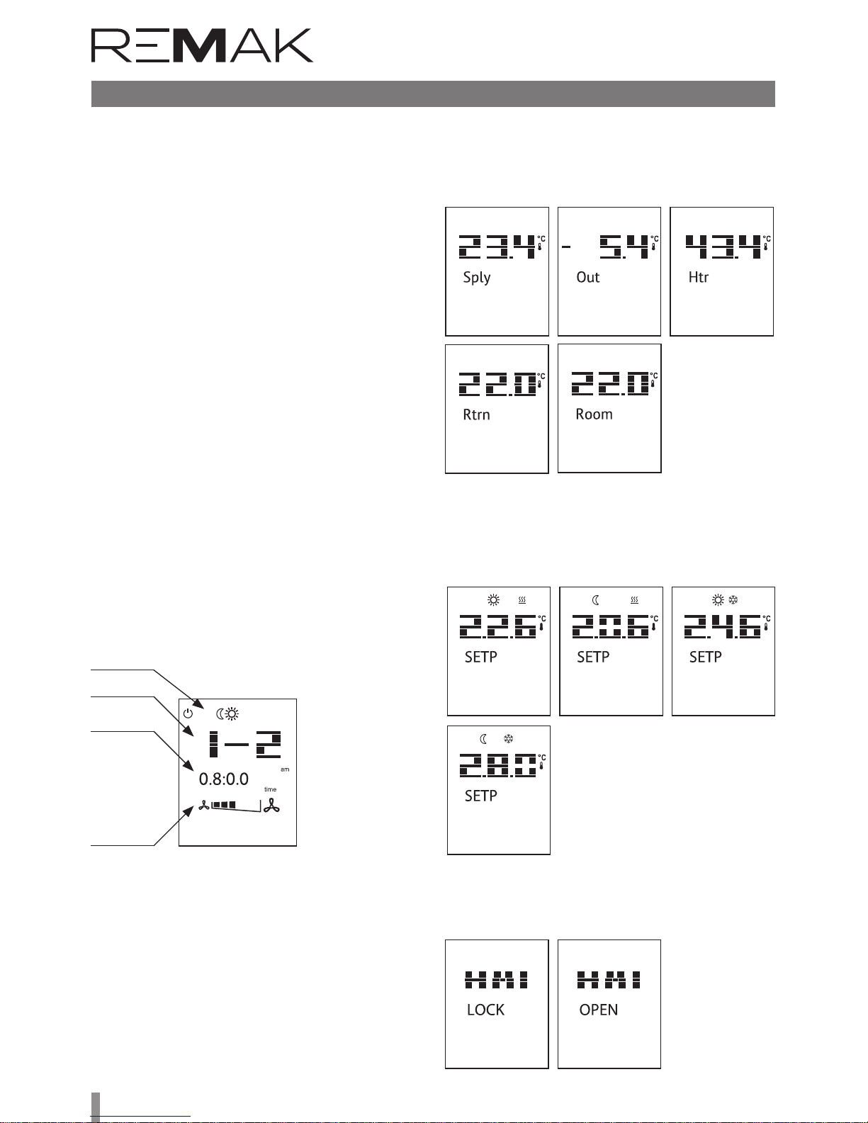
26
Control (HMI-SG)
Time Schedule Compilation Procedure
1) Press the Program (T3) button to enter the time schedule
configuration menu for each day of the week.
B HMI SG displays the first day of the week, i.e. Monday. Up to
6 time windows ((1-1 to 1-6) can be set for each day.
3) e Mode (T8) button enables you to select a day by cycling
through the week days (1-2-3-4-5-6-7-A). e "A" option is used
to set the time schedule for business days (1 – 5) simultaneously. If you make any change to the "A" time schedule, the
settings of the "A" day will be copied to all business days.
4) e Power (T1) button is used to assign the selected time
window with an operating mode (Stop-Economy-Comfort).
5) e Fan (T7) button is used to set the fan operation speed
stage (st. 1 – st. 5).
6) e Minus (T4) and Plus (T5) buttons are used to set the
beginning of the time window; to confirm the time setting,
press the OK (T6) button.
7) Once the beginning of the time window has been set, move
to the next settings in the time window.
8) If you set the beginning of the time window to "--:--", the
window will be disabled.
9) Press and hold the OK (T6) button to go back one step in
the time schedule settings within the set time.
10) Press and hold the Fan (T7) button to go back one step in
the time schedule settings within the fan speed stage settings.
11) Press and hold the Mode (T8) button to move one step
back (a weekday selection).
12) Press the Program (T3) or Presence (T2) button to exit
the Time Schedule Settings menu.
13) If no settings are performed in the time schedule within
1 minute, the menu will be automatically le..
time window
fan speed
stage setting
(T7)
operating mode
setup (T1)
time setup
(T4), (T5)
Quick Menu:
is enables quick access to the temperature and selected
value monitoring without editing.
Use the Minus (T4) and Plus (T5) to switch between the
temperature values.
Use the Program (T3) or Presence (T2) buttons to exit the
Quick Menu. Only those values which are included within the
given version of the VCS unit are displayed.
Briefly press the OK (T6) button to display the values listed
below:
n Inlet temperature (Sply)
n Outdoor temperature (Out)
Press and hold the OK (T6) button to display the values
listed below:
n Comfort temperature mode (heating)
n Economy temperature mode (heating)
n Comfort temperature mode (cooling)
n Economy temperature mode (cooling)
Lock/Unlock the SG II buttons
Press and hold the Presence (T2) button to lock/unlock the
SG II controller in order to prevent unauthorised access to
the device control.
n Return water temperature (Htr)
n Outlet temperature (Rtrn)
n Room temperature (Room)

27
Control units VCS
Control (HMI-SG)
Additional Operating Modes
and Function Settings
Additional operating modes and functions can be activated
in the List of Data Points in the section Settings – Additional
Operating Modes, Functions. Once the respective mode or
function has been set, it is necessary to perform SW reset
using a specific data point 211 (Reset aer the configuration
of additional modes/functions).
Optional Additional Operating Modes
n Night Chilling
n Temperature start-Up
n Time mode start optimization
Optional additional functions
n Outdoor Temperature-Dependent Fan Speed Compensa-
tion
n Heating/cooling dependent fan speed compensation
n Room (Outlet) Temperature-Dependent Fan Speed Com-
pensation
n Humidity-dependent Fan Speed Compensation
n Air Quality-Dependent Damper Position Compensation
n Heating/cooling–dependent fan speed compensation –
cooling sequence
n Cooling using heat recovery with rotary regenerator option
or using mixing damper
n Heating and mixing sequence order
n Outlet fan correction – using five-stage control (TRN
controllers)
n Difference between required and actual temperature
monitoring
n Damper and outlet fan blocking
n Room temperature measuring point selection
User Settings Backup and Recovery
It is advisable to perform backups especially before significant
changes in control parameter settings (PID controller factors, temperature setting for compensations or starting of
the optional additional modes), or always when the control
works optimally. Data backup or recovery can be performed
using the HMI controller in the List of Data Points, section
Checks – User Settings.
List of Data Points, Factory Settings
Warning:
e device parameters are structured and made available to
users in accordance with their user roles (access levels). ese
roles must be assigned to users by the system administrator
according to their expertise and responsibility for device operation. Access to the data points is also limited by the user role
level – for levels lower than Service, not all parameters (data
points) are displayed, respectively, they can be read without
being able to change (save) them. e Parameter List with a
combination of all possible air-handling unit applications is included in the List of data points under the highest access right.

28
List of Data Points (HMI-SG controller)
Monitor
Temperature
°C
001 G Temperature in the inlet °C
002 G Temperature in the room 1 °C
003 G Temperature in the room 2 °C
004 G Room unit 1 °C
005 G Room unit 2 °C
006 G Temperature in the outlet °C
007 G Outdoor temperature °C
008 G Return water temperature °C
009 G Heat exchanger freezing temperature °C
010 G Electric preheater temperature °C
011 G Water preheater temperature °C
012 G Electric reheater temperature °C
013 G Flue gas temperature °C
014 G Final room temperature (controlled) °C
Humidity
015 G Inlet air relative humidity %r.H.
016 G Room air relative humidity %r.H.
017 G Outdoor air relative humidity %r.H.
Pressure
018 G Pressure in the inlet Pa
019 G Pressure in the outlet Pa
020 G Air flow rate in the inlet m3/h
021 G Air flow rate in the outlet m3/h
CO2 (VOC, CO)
022 G CO2 (VOC, CO) concentration ppm
Performances
023 G Inlet fan output % (m3/h, Pa)
024 G Outlet fan output % (m3/h, Pa)
025 G 3rd fan output %
026 G Outlet level for the electric reheater %
027 G Heating mixing set valve position %
028 G Outlet level for cooling %
029 G Cooling output (stage)
030 G Electric preheater position %
031 G Outlet level for the electric heater %
032 G Heat pump output %
033 G Outlet position to the mixing damper %
034 G Heat exchanger control outlet position %
035 G Modulation burner outlet position %
036 G By-pass damper outlet position %
Operating states
037 G Fan state 0 -
1 Stage 1
2 Stage 2
3 Stage 3
4 Stage 4
5 Stage 5
038 G Electric pre-heater state 1 off
2 on
039 G Water pre-heater state 0 off
1 on
040 G Electric re-heater state 1 off
2 on
041 G Water heater pump state 0 off
1 on
042 G Pre-heating function of water heating 0 off
Menu HMI-SG
Parameter
Meaning
Factory Settings
Notation Reading Value Min Max
code level code level

29
Control units VCS
List of Data Points (HMI-SG controller)
Menu HMI-SG
Parameter
Meaning
Factory Settings
Notation Reading Value Min Max
code level code level
1 on
043 G Water cooler pump state 0 off
1 on
044 G Evaporator cooling stage 1 off
2 Stage 1
3 Stage 2
045 G Inverter cooling stage (inverter) 0 off
1 on
046 G Inverter cooling stage (step1+inverter) 0 off
1 on
047 G Heat pump operating state 0 out of operation
1 cooling
2 heating
048 G Electric heater operating state 1 off
2 on
049 G Gas Burner operating states (stages) 1 off
2 Stage 1
3 Stage 2
Current modes
050 G Fan output stages (external equipment) 0 Auto
1 off
2 Stage 1
3 Stage 2
4 Stage 3
5 Stage 4
6 Stage 5
051 G AHU current operating mode 0 Stop
1 Comfort
2 Economy
3 4 Optimized start
5 Night chilling
6 Temperature start-up
7 Night turning
8
9 Fire mode
10 Safety stop
11 Fan run-out
12 Start
Current temperature control values
052 G Calculated required temperature for heating with cascade control °C
053 G Calculated required temperature for cooling with cascade control °C
054 G Calculated required temperature for heating °C
055 G Calculated required temperature for cooling °C
056 G Current temperature-dependent control (inlet, room, outlet) 0 room
1 outlet
2 inlet
Current humidity values
058 G Calculated absolute inlet air humidity g/kg
059 G Calculated inlet air humidity enthalpy kJ/kg
060 G Calculated absolute room air humidity g/kg
061 G Calculated room air humidity enthalpy kJ/kg
062 G Calculated absolute outdoor air humidity g/kg
063 G Calculated outdoor air humidity enthalpy kJ/kg
064 G Request for dehumidification %
065 G Request for humidification %

30
List of Data Points (HMI-SG controller)
Menu HMI-SG
Parameter
Meaning
Factory Settings
Notation Reading Value Min Max
code level code level
066 G Humidifier state 0 off
1 on
Settings
Temperature modes
101 A 102 G Comfort - cooling 24.6 0 99 °C
103 A 104 G Comfort - heating 22.6 0 99 °C
105 A 106 G Economy - cooling 28 0 99 °C
107 A 108 G Economy - heating 20.6 0 99 °C
109 A 110 G Required temperature for cooling, Temperature start-up 15 -64 64 °C
111 A 112 G Required temperature for heating, Temperature start-up 25 -64 64 °C
113 A 114 G Required room temperature , Night chilling (control for inlet) 22 -64 64 °C
115 A 116 G Required room temperature , Boost (control for inlet) 20 -64 64 °C
117 A 118 G Required temperature for cooling, Boost 15 -64 64 °C
119 A 120 G Required temperature for heating, Boost 25 -64 64 °C
Cascade control limitation - limiter
121 S 122 A Max. difference between room temperature and inlet temperature 10 0 64 °C
123 S 124 A Min. difference between room temperature and inlet temperature 10 0 64 °C
Operation mode
125 A 126 G AHU manual control (Temperature mode, fan output stage) 0 Auto Stop
1 Stop
2 Economy; St1
3 Comfort; St1
4 Economy; St2
5 Comfort; St2
6 Economy; St3
7 Comfort; St3
8 Economy; St4
9 Comfort; St4
10 Economy; St5
11 Comfort; St5
127 A 128 G AHU start-up time-out aer power supply failure 10 0 9999 s
External control
129 U 130 G External contact function definition (Ext. control 1 contact) 0 Start function 0
1 Start and Stop function
131 U 132 G
Transition time from ext. control mode to AUTO mode (Ext. control 1
contact)
0 0 23 h
133 U 134 G Fan output stage setting (Ext. control 1 contact or 2 contacts) 0 Auto 2
1 off
2 Stage 1
3 Stage 2
4 Stage 3
5 Stage 4
6 Stage 5
135 U 136 G Temperature mode setting (Ext. control 1 contact or 2 contacts) 0 Comfort 0
1 Economy
137 U 138 G Fan output stage setting "Higher" (Ext. control 2 contacts) 0 Auto 5
1 off
2 Stage 1
3 Stage 2
4 Stage 3
5 Stage 4
6 Stage 5
139 U 140 G Temperature mode setting "Higher" (Ext. control 2 contacts) 0 Comfort 0
1 Economy
Fans - Modbus
Control limits
141 A Inlet fan output St1 setting 0.1 % (m3/h, Pa)

31
Control units VCS
List of Data Points (HMI-SG controller)
Menu HMI-SG
Parameter
Meaning
Factory Settings
Notation Reading Value Min Max
code level code level
142 A Inlet fan output St1 setting (a factor of 10) % (m3/h, Pa)
143 A Inlet fan output St2 setting 25 % (m3/h, Pa)
144 A Inlet fan output St2 setting (a factor of 10) % (m3/h, Pa)
145 A Inlet fan output St3 setting 50 % (m3/h, Pa)
146 A Inlet fan output St3 setting (a factor of 10) % (m3/h, Pa)
147 A Inlet fan output St4 setting 75 % (m3/h, Pa)
148 A Inlet fan output St4 setting (a factor of 10) % (m3/h, Pa)
149 A Inlet fan output St5 setting 100 % (m3/h, Pa)
150 A Inlet fan output St5 setting (a factor of 10) % (m3/h, Pa)
151 A Outlet fan output St1 setting 0.1 % (m3/h, Pa)
152 A Outlet fan output St1 setting (a factor of 10) % (m3/h, Pa)
153 A Outlet fan output St2 setting 25 % (m3/h, Pa)
154 A Outlet fan output St2 setting (a factor of 10) % (m3/h, Pa)
155 A Outlet fan output St3 setting 50 % (m3/h, Pa)
156 A Outlet fan output St3 setting (a factor of 10) % (m3/h, Pa)
157 A Outlet fan output St4 setting 75 % (m3/h, Pa)
158 A Outlet fan output St4 setting (a factor of 10) % (m3/h, Pa)
159 A Outlet fan output St5 setting 100 % (m3/h, Pa)
160 A Outlet fan output St5 setting (a factor of 10) % (m3/h, Pa)
161 A 162 U 3rd fan output St1 setting 0.1 0.1 100 %
163 A 164 U 3rd fan output St2 setting 25 0.1 100 %
165 A 166 U 3rd fan output St3 setting 50 0.1 100 %
167 A 168 U 3rd fan output St4 setting 75 0.1 100 %
169 A 170 U 3rd fan output St5 setting 100 0.1 100 %
171 A 172 U Fan run-out aer unit stop shut-down 180 0 9999 s
570 A
Enabling the fan run-out according to DEV 0 No 1
1 Yes
571 A
Unit run-out – blocking by the minimum outside temperature -15 -64 64 °C
572 A
Unit run-out – blocking by the maximum outside temperature 5 -64 64 °C
573 A
Unit run-out – time 5 1 60 Min
Inlet backup – single-speed motors
173 A 174 U Failure flow evaluation time-out aer main fan start-up 180 0 9999 s
175 A 176 U Failure flow evaluation time-out aer backup fan start-up 180 0 9999 s
181 U Information – backup activation 0 non-activated
1 activated
Outlet backup - single-speed motors
177 A 178 U Failure flow evaluation time-out aer main fan start-up 180 0 9999 s
179 A 180 U Failure flow evaluation time-out aer backup fan start-up 180 0 9999 s
182 U Information - backup activation 0 non-activated
1 activated
TRN correction
183 A 183 A Common for all operating stages St 0 - 4 stages 0
1 - 3 stages
2 - 2 stages
3 - 1 stage
4 0
5 + 1 stage
6 + 2 stages
7 + 3 stages
8 + 4 stages
184 A 184 A For operating stage St1 0 - 4 stage 0
1 - 3 stage
2 - 2 stage
3 - 1 stage
4 0

32
List of Data Points (HMI-SG controller)
Menu HMI-SG
Parameter
Meaning
Factory Settings
Notation Reading Value Min Max
code level code level
5 + 1 stage
6 + 2 stages
7 + 3 stages
8 + 4 stages
185 A 185 A For operating stage St2 0 - 4 stage 0
1 - 3 stage
2 - 2 stage
3 - 1 stage
4 0
5 + 1 stage
6 + 2 stages
7 + 3 stages
8 + 4 stages
186 A 186 A For operating stage St3 0 - 4 stage 0
1 - 3 stage
2 - 2 stage
3 - 1 stage
4 0
5 + 1 stage
6 + 2 stages
7 + 3 stages
8 + 4 stages
187 A 187 A For operating stage St4 0 - 4 stage 0
1 - 3 stage
2 - 2 stage
3 - 1 stage
4 0
5 + 1 stage
6 + 2 stages
7 + 3 stages
8 + 4 stages
188 A 188 A For operating stage St5 0 - 4 stage 0
1 - 3 stage
2 - 2 stage
3 - 1 stage
4 0
5 + 1 stage
6 + 2 stages
7 + 3 stages
8 + 4 stages
TRN – fan start-up (without outlet for dampers)
189 S 189 S Forced fan start-up time setting to Stage 1 20 0 99 s
Two-speed motors
190 A 191 U Transition time interval from speed 1 to speed 2 15 0 999 s
192 A 193 U Transition time-out from speed 2 to speed 1 12 0 99 s
Inlet temperature limitation
194 S 194 S Minimum inlet air temperature 15 0 64 °C
195 S 195 S Maximum inlet air temperature 35 0 64 °C
Additional operating modes, functions
196 S 196 S Outdoor temperature dependent fan speed compensation 0 No 0
1 Yes
197 S 197 S Heating/cooling dependent fan speed compensation 0 No 0
1 Heating
2 Cooling

33
Control units VCS
List of Data Points (HMI-SG controller)
Menu HMI-SG
Parameter
Meaning
Factory Settings
Notation Reading Value Min Max
code level code level
3 Heating + Cooling
198 S 198 S Air quality dependent fan speed compensation 0 No 1
1 Yes
199 S 199 S Room (outlet) temperature dependent fan speed compensation 0 No 0
1 Yes
230 S 230 S Humidity-dependent fan speed compensation 0 No 0
1 Yes
231 S 231 S Limitation of dehumidification during heating 0 No 0
1 Yes
201 S 201 S Difference between required and actual temperature monitoring 0 No 0
1 inlet
2 room
3 Inlet+room
202 S 202 S Air quality dependent damper position compensation 0 No 0
1 Yes
246 S 246 S Humidity-dependent mixing damper position compensation 0 No 0
1 Yes
247 S 247 S Max. limit of fresh air according to T outdoor (ventilation unit) 0 No 0
1 Yes
203 S 203 S Cooling using HR (RHE, BP PE, mixing damper) 0 without HR cooling 3
1 RHE, BP PE
2 mixing damper
3 RHE+ damper
204 S 204 S
Heating/cooling dependent fan speed compensation-cooling sequence
(fan, cooler)
0 fan+cooler 1
1 cooler+fan
205 S 205 S Mixing heating sequence (damper, heater) 0 damper+heater 0
1 heater+damper
206 S 206 S Night cooling 0 without chilling
1 with chilling
207 S 207 S Temperature start-up 0 N/A 0
1 heating
2 cooling
3 heating + cooling
208 S 208 S Time mode start optimization 0 N/A 0
1 heating
2 cooling
3 heating + cooling
209 S 209 S Damper and outlet fan blocking 0 N/A 0
1 dampers
2 dampers+fan
210 S 210 S Outlet fan correction type (TRN controllers) 0 separate stages 0
1 shared stages
211 S 211 S Reset aer configuration of additional modes/functions 0 without reset
1 reset
212 S 212 S Room temperature measuring point selection 0 average 3
1 minimum
2 maximum
3 room temp. sensor 1
4 room temp. sensor 2
5 HMI-SG 1 controller
6 HMI-SG 2 controller
Control signal characteristic
213 A 213 A Control signal 0-10 V or 2-10 V, heating 0 0-10V
1 2-10V 1
214 A 214 A Control signal 0-10 V or 2-10 V, cooling 0 0-10V
1 2-10V 1
215 A 215 A Control signal 0-10 V or 2-10 V, mixing damper 0 0-10V
1 2-10V 1

34
List of Data Points (HMI-SG controller)
Menu HMI-SG
Parameter
Meaning
Factory Settings
Notation Reading Value Min Max
code level code level
216 A 216 A Control signal 0-10 V or 2-10 V, heat exchanger by-pass damper 0 0-10V
1 2-10V 1
217 A 217 A Control signal 0-10 V or 2-10 V, chamber by-pass damper 0 0-10V
1 2-10V 1
Required inlet temperature extra set-point
218 A 219 G
Required inlet temperature extra set-point (applied when el. re-heating or
heat pump is removed from the main sequence)
20 0 99 °C
220 S 220 S Fan start-up delay (aer damper) 20 0 9999 s
221 S 221 S
Outdoor-dependent fan speed interlocking
-60 -64 64 °C
Control – Flow (Pressure)
222 A 223 U Setting range of flow sensor - inlet (a factor of 100) 8000 0 2*105 m3/h
224 A 225 U Setting range of flow sensor - outlet (a factor of 100) 8000 0 2*105 m3/h
226 A 227 U Setting range of pressure sensor - inlet (a factor of 100) 6000 0 7000 Pa
228 A 229 U Setting range of pressure sensor - outlet (a factor of 100) 6000 0 7000 Pa
232 A 233 U K factor – inlet 95 0 9999
234 A 235 U K factor – outlet 95 0 9999
236 A 237 U NunberInletFan 1 1 100
238 A 239 U NunberOutletFan 1 1 100
240 S K Factor - Enabled 0 No
1 Yes 1
Inputs configuration
241 S Reverse function of fault input for Cooling or Heat Pump 0 Normal 0
1 Reversed
Device configuration
270 U Regulation supply fan 0 none
1 1 stage
2 5 stage (TRN)
3 V10
4 V100
5 V10 + back-up
6 V100 + back-up
7 2xV10
8 2xV100
9 2xV10 + back-up
10 2xV100 + back-up
271 U Regulation exhaust fan 0 none
1 1 stage
2 5 stage (TRN)
3 V10
4 V100
5 V10 + back-up
6 V100 + back-up
7 2xV10
8 2xV100
9 2xV10 + back-up
10 2xV100 + back-up
272 U Regulation additional fan 0 none
1 1 stage
2 5 stage (TRN)
3 V10
4 V100
7 2xV10
8 2xV100
273 U Heating 0 no
1 water
2 electric
3 gas

35
Control units VCS
List of Data Points (HMI-SG controller)
Menu HMI-SG
Parameter
Meaning
Factory Settings
Notation Reading Value Min Max
code level code level
274 U Heat pump 0 no
1 variation A
2 variation B
275 U Type of gas heating 0 1 stage
1 2 stage
2 modulation
276 U Byppas damper gas heater 0 no
1 yes
277 U Cooling 0 no
1 water
2 1 step
3 2 step
4 inverter
5 inverter + 1 step
278 U Heat recovery 0 no
1 plate
2 wheel
3 glycol
279 U Mixing 0 no
1 yes
280 U Preheating 0 no
1 water
2 electric
281 U Extra heating 0 no
1 electric
282 U Temperature control mode 0 supply
1 cascade - room
2 cascade - return
283 U Humidity control mode 0 no
1 room
2 supply
3 cascade - room
Control parameters
Temperature start-up
301 A 302 U Cooling trigger temperature 30 -64 64 °C
303 A 304 U Heating trigger temperature 25 -64 64 °C
305 A 306 U Hysteresis 1 0.1 64 °C
307 A 308 U Heating and cooling blocking time 30 0 999 min
309 A 310 U Operating time 0 0 999 min
Night colling
311 A 312 U Temperature hysteresis 3 0 64 °C
313 A 314 U Minimum outdoor temperature setting 12 -64 64 °C
315 A 316 U Outdoor temperature and room temperature difference 5 1 64 °C
317 A 318 U Minimum night chilling operating time 30 0 999 min
Boost function
319 A 320 U Pre-set interval before time program start-up 60 0 999 min
321 A 322 U Temperature hysteresis 0.5 -64 64 °C
Required temperature compensation
323 A 324 U Cooling initial point (outdoor temperature) 25 -64 64 °C
325 A 326 U Cooling end point (outdoor temperature) 30 -64 64 °C
327 A 328 U Maximum cooling compensation (required value) 2 -64 64 dK
329 A 330 U Heating initial point (outdoor temperature) 5 -64 64 °C
331 A 332 U Heating end point (outdoor temperature) -20 -64 64 °C
333 A 334 U Maximum heating compensation (required value) -1 -64 64 dK
335 U Required cooling value current shi -64 64 °C
336 U Required heating value current shi -64 64 °C
Outdoor temperature dependent fan speed compensation
337 A 338 U Cooling initial point (outdoor temperature) 25 -64 64 °C

36
List of Data Points (HMI-SG controller)
Menu HMI-SG
Parameter
Meaning
Factory Settings
Notation Reading Value Min Max
code level code level
339 A 340 U Cooling end point (outdoor temperature) 30 -64 64 °C
341 A 342 U Maximum cooling compensation (speed) 0 -100 100 %
343 A 344 U Heating initial point (outdoor temperature) 5 -64 64 °C
345 A 346 U Heating end point (outdoor temperature) -20 -64 64 °C
347 A 348 U Maximum heating compensation (speed) 0 -100 100 %
349 U Current cooling speed compensation -100 100 %
350 U Current heating speed compensation -100 100 %
Room (outlet) temperature dependent fan speed compensation
351 A 351 A Compensation function setting
0 increase 0
1 decrease
352 U
Actual compensation
0 100 %
353 A 353 A Required room temperature 20 0 99 °C
Heating/cooling dependent fan speed compensation
354 A 354 A Heating temperature hysteresis 1 0 20 °C
355 A 355 A Cooling temperature hysteresis 1 0 20 °C
356 U Heating compensation display 0 100 %
357 U Cooling compensation display 0 100 %
Air quality dependent compensation (damper position/fan speed)
358 A 359 U Compensation function setting (according to the sensor characteristics) 0 Normal 0
1 Inverted
360 A 361 U Required (allowable) value of the CO2, VOC, (CO) concentration 800(50) 0 3000 ppm
362 A 363 U CO2, VOC, (CO) sensor range setting 2000(300) 0 3000 ppm
364 U CO2, VOC (CO) compensation rate display 0 100 %
Sequence
Heat pump - heating
365 A 366 U Outdoor temperature dependent heat pump blocking -8 -45 35 °C
367 A 368 U
Temp. hysteresis applied for outdoor temperature dependent heat pump
unblocking
3 1 10 °C
369 A 370 U Minimum operating time for heat pump heating 60 0 9999 s
371 A 372 U Re-heating blocking 120 5 600 s
373 A 374 U Heat pump switching on 20 0 100 %
375 A 376 U Digital output opening hysteresis 10 1 100 %
377 U Information - outdoor temperature dependent heat pump heating blocking 0 inactive
1 active
Heat pump - cooling
378 A 379 U Outdoor temperature dependent heat pump blocking 14 -45 35 °C
380 A 381 U
Tep. hysteresis applied for outdoor temperature dependent heat pump
unblocking
3 1 10 °C
382 A 383 U Minimum operating time for heat pump cooling 60 0 9999 s
384 A 385 U Re-cooling blocking 120 5 600 s
386 A 387 U Heat pump switching on 20 0 100 %
388 A 389 U Digital output opening hysteresis 10 1 100 %
390 A 391 U Heat pump low reference signal setting for A output 30 0 50 %
392 U Information - outdoor temperature dependent heat pump cooling blocking 0 inactive
1 active
Heat Pump - Special
260 S Inversion signal for Heat Pump – heating 0 Off
1 On
261 S Inversion signal for Heat Pump – cooling 0 Off
1 On
262 S Special signal 0-10V (Daikin) switchover 0 Off
1 On
263 S e difference between the demand and the real signal to determine St2 40 0 100 %
264 S Time needed to pass from 0 to 100% 120 0 500 s
265 S e signal voltage request of heating (Toshiba) 3.25 0 10 V
266 S e signal voltage request of cooling (Toshiba) 6.25 0 10 V
267 S e signal voltage request of STOP (Toshiba) 0 0 10 V

37
Control units VCS
List of Data Points (HMI-SG controller)
Menu HMI-SG
Parameter
Meaning
Factory Settings
Notation Reading Value Min Max
code level code level
268 S e signal voltage request of START (Toshiba) 8 0 10 V
Cooling
393 A 394 U Outdoor temperature to enable cooling – all versions 12 -64 64 °C
395 A 396 U Minimum pump operating time – water version 180 0 9999 s
397 A 398 U Pump downtime to the pump turning activation – water version 168 0 9999 h
399 A 401 U Active pump turning time – water version 60 0 9999 s
397 A 398 U
Minimum operating time, single-stage condensing unit – version with
single-stage condensing unit
60 0 9999 s
399 A 401 U Re-cooling blocking time – versions with single-, two-stage condensing units 120 5 600 s
402 A 403 U
Retention time during transition from Stage 1 to Stage 2 – version with
two-stage condensing unit
360 5 600 s
404 A 405 U
Cooling request dependent evaporator Stage 1 switch-on – version with
two-stage condensing unit
20 0 100 %
406 A 407 U
Cooling request dependent evaporator Stage 2° switch-on – version with
two-stage condensing unit
70 0 100 %
408 A 409 U Hysteresis for transition from Stage 1 to Stage 2, two-stage condensing unit 10 0 20 %
410 A 411 U Minimum inverter operating time – version with inverter 10 0 9999 s
412 A 413 U
Inverter re-start blocking time – version with single-stage condensing
unit + inverter
60 0 300 s
413 A
AO cooling signal inversion 0 Switched OFF
1 Switched ON
Water heating with pre-heating function
414 A 415 U
Outdoor temperature-dependent pump start-up in the AHU Stop and
Run mode
5 -64 64 °C
416 A 417 U Minimum pump run time 180 0 9999 s
418 A 419 U Pump downtime to the pump turning activation 168 0 9999 h
420 A 421 U Active pump turning time 60 0 9999 s
422 A 423 U Active function preheating of water operation time 120 0 600 s
424 A 425 U Pre-heating function blocking time between AHU unit shut-down and restart 5 0 30 min
426 A 427 U Water heater circuit heating curve setting at the AHU start-up X1 -10 -30 5 °C
428 A 429 U Water heater circuit heating curve setting at the AHU start-up Y1 100 0 100 %
430 A 431 U Water heater circuit heating curve setting at the AHU start-up X2 10 0 50 °C
432 A 433 U Water heater circuit heating curve setting at the AHU start-up Y2 10 0 100 %
434 A 435 U Stop to Run mode switching delay AP trigger value 60 0 600 s
436 A 437 U Water heat exchanger dependent AP trigger value – AHU in Run mode 15 0 50 °C
438 A 439 U Water heat exchanger dependent AP trigger value - AHU in Stop mode 30 0 50 °C
440 A 441 U Inlet air dependent AP evaluation enabling delay aer the unit start-up 60 0 600 s
442 A 443 U Inlet air temperature dependent AP start-up – failure alarm A 6 -64 64 °C
444 A 445 U Inlet air temperature dependent AP start-up 8 -64 64 °C
446 A 447 U Maximum return water temperature 70 20 140 °C
Water pre-heating
448 A 449 U Outdoor dependent pre-heating (pump) start-up 5 -50 15 °C
450 A 451 U Pump downtime to the pump turning activation 168 0 9999 h
452 A 453 U Active pump turning time 30 0 9999 s
454 A 455 U Minimum pump run time 30 0 9999 s
Heating water source switching
456 A 457 U Limit value for heating 15 5 25 °C
458 A 459 U Start-up sequence delay 120 10 600 s
Gas heating
460 A 461 U Cooling sequence enabling 0 without cooling
1 with cooling
462 A 463 U Minimum burner run time 150 0 600 s
464 A 465 U Minimum burner downtime 150 0 600 s
466 A 467 U Burner restart protection time (burner Stage 1) 150 0 600 s
468 A 469 U Modulation burner opening/closing speed (burner Stage 1) 5 0 20 %/s
470 A 471 U Heating request value for the burner Stage 2 switch-off 40 10 100 %
472 A 473 U Maximum flue-gas temperature setting for alarm 230 210 400 °C
474 A 475 U Maximum flue-gas temperature 210 160 p.472 °C
476 A 477 U Requested flue-gas temperature 160 150 210 °C
478 A 479 U Minimum flue-gas temperature 150 100 160 °C
Electric heating
480 A 481 U Electric heating switching on – request for heating 20 0 100 %
482 A 483 U Electric heating hysteresis 10 1 100 %

38
List of Data Points (HMI-SG controller)
Menu HMI-SG
Parameter
Meaning
Factory Settings
Notation Reading Value Min Max
code level code level
Mixing
484 A 484 U Minimum fresh air value setting 20 0 100 %
484 A 484 U Minimum fresh air value setting – Comfort mode (pool unit) 20 0 100 %
485 A 485 A Minimum fresh air value setting – Economy mode (pool unit) 20 0 100 %
484 A 485 U Minimum fresh air flow rate setting 20 0 100 %
486 A 487 U Starting temperature for mixing damper wide-open position 15 -64 64 °C
488 A 489 U Starting time for mixing damper wide-open position 60 0 600 s
490 U Mixing damper control signal recurrence vale (normal/inverse) 100 0 100 %
Max. limit of fresh air function (ventilation unit)
563 A 564 U Max. limit of fresh air according to T outdoor 40 0 100 %
565 A 566 U T outdoor from which the Max. limit of fresh air is activated -10 -100 100 °C
567 U Information about the Max. limit of fresh air activation 0 Inactive
1 Active
491 A 492 U Required temperature for pre-heating -20 -50 10 °C
493 A 494 U Outdoor dependent electric pre-heating blocking -30 -50 10 °C
495 A 496 U Heating request dependent el. –pre-heating switch-on 20 0 100 %
497 A 498 U Hysteresis for electric pre-heater switch-off 10 0 100 %
Electric reheating
502 A 503 U Heating request dependent electric re-heating start-up for Stage 1 20 0 100 %
504 A 505 U Hysteresis for electric re-heating switch-off 10 1 100 %
506 A 507 U Fan stage dependent outlet limitation ST1 100 0 100 %
508 A 509 U Fan stage dependent outlet limitation ST2 100 0 100 %
510 A 511 U Fan stage dependent outlet limitation ST3 100 0 100 %
512 A 513 U Fan stage dependent outlet limitation ST4 100 0 100 %
514 A 515 U Fan stage dependent outlet limitation ST5 100 0 100 %
Heat recovery
516 A 517 U Freezing determination temperature exchanger 1 -64 64 °C
518 A 519 U Start temperature for maximum - HRE speed/volume open BP PE 15 -64 64 °C
520 A 521 U Start time for maximum - HRE speed/volume open BP PE 60 0 600 s
522 A 523 U Heat recovery request dependent HRE run enabling 38 0 100 %
524 A 525 U Hysteresis for HRE run stop 5 0 100 %
526 U Information - antifreeze protection start-up 0 inactive
1 active
Night turning
527 A 528 U Time to next turning 3 0 9999 h
529 A 530 U Active turning time 300 0 9999 s
Humidification
531 A 532 U
Relative set-point of relative humidity - Comfort 40 0 100 %r.H.
535 A 536 U
Relative set-point of humidity - Economy 30 0 100 %r.H.
541 A 542 U
Humidification blocking in summer 0 Ne 0
1 Ano
545 U Humidification output %
550 G
Calculated current humidification set-point in the cascade
Dehumidification
533 A 534 U
Dehumidification relative set-point - Comfort 60 0 100 %r.H.
537 A 538 U
Dehumidification relative set-point - Economy 70 0 100 %r.H.
533 A 534 U Dehumidification required relative value 60 0 100 %r.H.
537 A 538 U Dehumidification required absolute value 12 0 100 g/kg
539 A 540 U Maximum humidity required value 80 0 100 %r.H.
543 U Current humidity value
544 U Maximum humidity %
546 U Dehumidification output %
547 U Dew point °C
548 A 549 U Dew point deviation 1 -64 64 °C
551 G Calculated current dehumidification required value for cascade control %r.H.
Humidity-dependent fan speed compensation
552 A 553 U Humidity required value for compensation 50 0 100 %r.H.
554 A 555 U Fan speed compensation function 0 increase 0

39
Control units VCS
List of Data Points (HMI-SG controller)
Menu HMI-SG
Parameter
Meaning
Factory Settings
Notation Reading Value Min Max
code level code level
List of Data Points (HMI-SG controller)
1 decrease
556 U Compensation display %
Humidity-dependent mixing damper position compensation
560 A 561 U Fan speed compensation function 0 Increase 0
1 Decrease
562 U Compensation display %
Control constants
Cooling factors (all versions)
601 S 602 A Proportional factor -5
603 S 604 A Integrating factor 60 s
605 S 606 A Derivative factor 0 s
Heat pump factors - heating
607 S 608 A Proportional factor 5
609 S 610 A Integrating factor 300 s
611 S 612 A Derivative factor 0 s
Heat pump factors - cooling
613 S 614 A Proportional factor -5
615 S 616 A Integrating factor 300 s
617 S 618 A Derivative factor 0 s
Room (outlet) temperature dependent fan speed compensation
619 S 620 A Proportional factor 20
621 S 622 A Integrating factor 0 s
623 S 624 A Derivative factor 0 s
Heating dependent fan speed compensation
625 S 626 A Proportional factor 5
627 S 628 A Integrating factor 120 s
629 S 630 A Derivative factor 0 s
Cooling dependent fan speed compensation
631 S 632 A Proportional factor -10
633 S 634 A Integrating factor 120 s
635 S 636 A Derivative factor 0 s
Air quality CO2 (VOC,CO) dependent compensation (damper position/
fan speed)
637 S 638 A Proportional factor -0.3
639 S 640 A Integrating factor 300 s
641 S 642 A Derivative factor 0 s
Mixing
643 S 644 A Proportional factor 7
645 S 646 A Integrating factor 45 s
647 S 648 A Derivative factor 15 s
Heat recovery RHE/BP PE
649 S 650 A Proportional factor 3
651 S 652 A Integrating factor 60 s
653 S 654 A Derivative factor 1 s
Heat recovery – antifreeze protection
655 S 656 A Proportional factor 20
657 S 658 A Integrating factor 150 s
659 S 660 A Derivative factor 0 s
Electric reheating
661 S 662 A Proportional factor 1
663 S 664 A Integrating factor 60 s
665 S 666 A Derivative factor 0 s
Electric pre-heating
667 S 668 A Proportional factor 5
669 S 670 A Integrating factor 120 s
671 S 672 A Derivative factor 0 s
Water heating with pre-heating function
673 S 674 A Proportional factor – AP from return water 20
675 S 676 A Integrating factor - AP from return water 90 s

40
Menu HMI-SG
Parameter
Meaning
Factory Settings
Notation Reading Value Min Max
code level code level
List of Data Points (HMI-SG controller)
677 S 678 A Derivative factor - AP from return water 0 s
679 S 680 A Proportional factor - AP from inlet air 50
681 S 682 A Integrating factor - AP from inlet air 0 s
683 S 684 A Derivative factor - AP from inlet air 0 s
685 S 686 A Proportional factor - AP from max. return water temperature -3
687 S 688 A Integrating factor - AP from max. return water temperature 300 s
689 S 690 A Derivative factor - AP from max. return water temperature 0 s
691 S 692 A Proportional factor - from temperature request 5
693 S 694 A Integrating factor - from temperature request 150 s
695 S 696 A Derivative factor - from temperature request 0 s
Electric heating
697 S 698 A Proportional factor 2
699 S 701 A Integrating factor 60 s
702 S 703 A Derivative factor 0 s
Gas heating
704 S 705 A Proportional factor - burner 5
706 S 707 A Integrating factor - burner 60 s
708 S 709 A Derivative factor - burner 0 s
710 S 711 A Proportional factor - bypass damper -5
712 S 713 A Integrating factor - bypass damper 120 s
714 S 715 A Derivative factor - bypass damper 0 s
716 S 717 A Proportional factor - maximum temperature of flue gas 10
718 S 719 A Integrating factor - maximum temperature of flue gas 120 s
720 S 721 A Derivative factor - maximum temperature of flue gas 0 s
722 S 723 A Proportional factor - minimum temperature of flue gas -10
724 S 725 A Integrating factor - minimum temperature of flue gas 120 s
726 S 727 A Derivative factor - minimum temperature of flue gas 0 s
Cascade temperature control
728 S 729 A Proportional factor 10
730 S 731 A Integrating factor 1200 s
Cascade humidity control
732 S 733 A
Proportional factor 4
734 S 735 A
Integrating factor 0 s
Humidification
736 S 737 A
Proportional factor 5
738 S 739 A
Integrating factor 120 s
740 S 741 A
Derivative factor 0 s
732 S 733 A Proportional factor 4
734 S 735 A Integrating factor 0 s
Dehumidification
742 S 743 A Proportional factor -2
744 S 745 A Integrating factor 240 s
746 S 747 A Derivative factor 0 s
Humidity-dependent fan speed compensation
748 S 749 A Proportional factor -5
750 S 751 A Integrating factor 0 s
752 S 753 A Derivative factor 0 s
Constant Air Flow/Pressure Control - inlet
754 S 755 A Proportional factor 0.3
756 S 757 A Integration factor 30 s
758 S 759 A Differentiation factor 0 s
Constant Air Flow/Pressure Control - outlet
760 S 761 A Proportional factor 0.3
762 S 763 A Integration factor 30 s
764 S 765 A Differentiation factor 0 s
Checks, system and network settings
Humidity-dependent mixing damper position compensation
766 S 767 A Proportional factor -2
768 S 769 A Integrating factor 45 s

41
Control units VCS
Menu HMI-SG
Parameter
Meaning
Factory Settings
Notation Reading Value Min Max
code level code level
770 S 771 A Derivative factor 0 s
Difference between required and inlet temperature monitoring
801 A 802 G Maximum difference (±°C) 10 0 99 °C
803 A 804 G Minimum limit (°C) 10 0 99 °C
805 A 806 G Time delay aer AHU start-up (s) 60 0 9999 s
Difference between required and room (outlet) temperature monitoring
807 A 808 G Maximum difference (±°C) 10 0 99 °C
809 A 810 G Minimum limit (°C) 10 0 99 °C
811 A 812 G Time delay aer AHU start-up (s) 600 0 9999 s
Remote fault
813 A 814 G Failure class selection to digital output 0 Failure A 1
1 Failure A+B
815 G Alarm message (generated depending on priorities) 0 Normal
1 Alarm
Fire mode
816 A 817 G Fan behaviour during fire selection 0 Stop 0
1 Inlet fan
2 Outlet fan
3 Both fans
818 A 819 G Fan output during fire selection 80 0 100 %
820 A 821 G Fire alarm activation inlet temperature 70 0 99 °C
822 A 823 G Fire alarm activation outlet temperature 50 0 99 °C
Alarm number for HMI
824 U Alarm number
System settings - control unit
825 A 825 A Failure acknowledgement (reset of all failures aer they have been removed) 0 No
1 Yes
826 S 826 S Soware reset of the controller 0 without reset
1 reset
827 S 827 S Control unit location building physical address 0 0 15
828 S 828 S Control unit location floor physical address 0 0 15
829 S 829 S Control unit device address 0 0 250
SD card
830 S Application load from SD card 0 No change
1 Loading
834 S Parameter save to SD card 0 Passive
1 Active
835 S Parameter save to SD card - successful 0 No
1 Yes
836 S Parameter load from SD card 0 Passive
1 Pasrtial
2 Full
837 S Parameter load SD card - successful 0 No
1 Yes
831 S 831 S Data point recovery (factory settings) 0 No
1 Yes
User settings
832 A 832 A Data point saving (user settings) 0 without saving
1 with saving
833 A 833 A Data point recovery (user settings) 0 No
1 Yes
ModBus
838 S Alarm 0 OK
1 Error
839 S 839 S Failure flow activation delay (at fan start-up) 45 0 600 s
840 S 840 S Failure flow activation delay (during fan run) 5 0 600 s
841 S 841 S ermo-contact (TK) failure activation delay (fans) 2 0 600 s
842 S 842 S Frequency inverter failure activation delay 2 0 600 s

42
Menu HMI-SG
Parameter
Meaning
Factory Settings
Notation Reading Value Min Max
code level code level
843 S 843 S Number of message repeating during error transfers 2
844 S 844 S Number of error transfers for communication failure evaluation 6
845 S 845 S Frequency inverter 1 address, inlet fan 1
846 S 846 S Frequency inverter 2 address, inlet fan backup or second inlet fan 2
847 S 847 S Frequency inverter 3 address, inlet fan twin backup 3
848 S 848 S Frequency inverter 4 address, inlet fan twin backup 4
849 S 849 S Frequency inverter 5 address, outlet fan 5
850 S 850 S Frequency inverter 6 address, outlet fan backup or second outlet fan 6
851 S 851 S Frequency inverter 7 address, outlet fan twin backup 7
852 S 852 S Frequency inverter 8 address, outlet fan twin backup 8
853 S 853 S Frequency inverter 9 address, 3rd auxiliary fan 9
854 S 854 S Frequency inverter 10 address, second 3rd auxiliary fan 10
857 S 857 S Frequency inverter 11 address, rotary heat exchanger 11
858 S 858 S Control unit Modbus resistance terminal 0 inactive
1 active
Network connection configuration
(Aer setting – the reset is required !!)
859 A DHCP 0 passive
1 active
860 A Settings IP[w] 192 0 255
861 A Settings IP[x] 168 0 255
862 A Settings IP[y] 1 0 255
862 A Settings IP[z] 199 0 255
864 U Actual IP[w]
865 U Actual IP[x]
866 U Actual IP[y]
867 U Actual IP[z]
868 A Settings mask [w] 255 0 255
869 A Settings mask [x] 255 0 255
870 A Settings mask [y] 255 0 255
871 A Settings mask [z] 0 0 255
872 U Actual mask [w]
873 U Actual mask [x]
874 U Actual mask [y]
875 U Actual mask [z]
876 A Settings gateway [w] 0 0 255
877 A Settings gateway[x] 0 0 255
878 A Settings gateway [y] 0 0 255
879 A Settings gateway [z] 0 0 255
880 U Actual gateway [w]
881 U Actual gateway [x]
882 U Actual gateway [y]
883 U Actual gateway [z]
System settings - room unit
884 S 884 S Transition to time program delay 1 0 23 h
885 A 885 A Byte address, Diagnostic mode – byte address 5
886 A 886 A Alarm mode 0 N/A 2
1 only aer alarm
2 constantly
887 S 887 S Room temperature display, combined or inlet temperature 0 Temp. from HMI-SG 0
1 Temperature average
2 Outlet Temperature
3 Temperature in the inlet
895 U 895 U Temperature unit display settings °C/°F 0 °C 0
1 °F
896 A 896 A Required value compensation setting +/- 3 0 12 °C
897 A 897 A Required value increment 0 Increment per 0.1 0 °C
1 Increment per 0.5 °C
43
Control units VCS
898 A 898 A Displayed time format - 12h/24h 0 24 h
1 12 h
Passwords
899 S 899 S Password for Service level access 0 9999
901 A 901 A Password for Admin level access 0 9999
902 U 902 U Password for User level access 0 9999
903 G 903 G Password for Guest level access 0 9999
Comunication with Building management system
(BMS) - (Aer settings - reset required !!)
LON
921 S 921 S Send heart beat (s) 2700 0 9999 s
922 S 922 S Receive heart beat (s) 3600 0 9999 s
923 S 923 S Min send intervall (s) 5 0 9999 s
924 S 924 S Service pin 0 inactive
1 active
925 S 925 S Out temperature value 0 of application 0
1 of communication
926 S 926 S Fire alarm (external) 0 of application 0
1 of communication
Modbus RTU - Slave (BMS)
925 S 925 S Out temperature value 0 of application
1 of communication
926 S 926 S Fire alarm (external) 0 of application
1 of communication
931 S 931 S Modbud Slave1 0 inactive
1 active
932 S 932 S Address Slave1 1
933 S 933 S Baud rate Slave1 default 9600 b/s
2400 (factor 10)
4800 (factor 10)
9600 (factor 10)
19200 (factor 10)
38400 (factor 10)
934 S 934 S Stop bits Slave1 0 One stop bit 1
1 Two stop bits
935 S 935 S Parity Slave1 0 Even 2
1 Odd
2 None
936 S 936 S Termination (resistor) Slave1 0 inactive 0
1 active
937 S 937 S Response timeout Slave1 5 0 3600 s
Menu HMI-SG
Parameter
Meaning
Factory Settings
Notation Reading Value Min Max
code level code level

44
List of Failures (HMI-SG controller)
Failure
Description
Class
Failure
Number
Failure Causes
Reduced humidification output
B 10
Reduced humidification output due to the temperature priority (swimming-pool unit)
– an information message.
Auxiliary Fan B 15
1.) Communication error between control unit and the auxiliary fan frequency inverter
(Modbus data bus) – inverter internal error; wrong settings of the frequency inverter data
points – bus communication protocol, data transfer rate, parity, number of stop-bits, communication timeout; poor connection of the bus cable to the frequency inverter terminals;
bus terminal resistance settings on the last frequency inverter has not been performed.
2.) Auxiliary fan failure (Modbus data bus) - thermo-contact, flow sensor
Auxiliary Fan - twin B 16
1.) Communication error between control unit and the auxiliary fan twin frequency inverter
(Modbus data bus) – inverter internal error; wrong settings of the frequency inverter data
points - bus communication protocol, data transfer rate, parity, number of stop-bits, communication timeout; poor connection of the bus cable to the frequency inverter terminals;
bus terminal resistance settings on the last frequency inverter has not been performed.
2.) Auxiliary fan twin failure (Modbus data bus) - thermo-contact, flow sensor
Backup fans
in the inlet
B 18
Main inlet fan failure (backup fan activated) - thermo-contact, flow sensor
A Class failure – inlet backup fan shutdown
Backup fans
in the outlet
B 19
Main outlet fan failure (backup fan activated) - thermo-contact, flow sensor
A Class failure - outlet backup fan shutdown
Communication, Modbus
B 23
Communication error between control unit and the fan or ROV frequency inverter (Modbus
data bus) - inverter internal error; wrong settings of the frequency inverter data points
– bus communication protocol, data transfer rate, parity, number of stop-bits, communication timeout; poor connection of the bus cable to the frequency inverter terminals;
bus terminal resistance settings on the last frequency inverter has not been performed.
Process communication KNX
B 23 Communication error between control unit and HMI-SG controller (KNX bus)
Room unit 1 Temperature
B 24 Disconnected or damaged HMI-SG1 controller
Room unit 2 Temperature
B 24 1) Disconnected or damaged HMI-SG2 controller
2) Wrong HMI-SG2 controller communication address setting (the same address with
the HMI-SG1 controller)
Outdoor temperature
B 25 Disconnected or damaged outdoor temperature sensor
Room temperature B 26 Disconnected or damaged room temperature sensor
Outlet tem-
perature
B 28 Disconnected or damaged outlet temperature sensor
Inlet temperature
difference
B 32
Information message on the difference between inlet and required temperatures, providing the Inlet and Required Temperature Difference Monitoring has been activated (in the
data point 201). If the temperature difference is higher than pre-set Maximum Difference
(data point 801) or if the inlet temperature drops below the pre-set minimum threshold
(data point 803), an information message is displayed.
Room temperature difference
B 33
Information message on the difference between room/outlet and required temperatures,
providing the Inlet and Required Temperature Difference Monitoring has been activated
(in the data point 201). If the temperature difference is higher than pre-set Maximum
Difference (data point 807) or if the room/outlet temperature drops below the pre-set
minimum threshold (data point 809), an information message is displayed.
45
Control units VCS
List of Failures (HMI-SG controller) (continuation)
Failure
Description
Failure
Class
Failure
Number
Failure Causes
Outdoor
temperature
dependent heat
pump blocking
B 35 Information message – e heat pump blocked due to outdoor temperature
Heat pump B 36 Heat pump failure – contact
Humidification B 37 Humidifier failure - contact
Filters B 39 Filter failure - contact
Fan operat-
ing hours
B 40
e pre-set fan operating hours have been exceeded; operating hours are set using the
HMI-DM, TM or HMI@Web controllers.
Cooling B 41 Cooling failure (direct expansion evaporation, inverter condensing unit) -contact
ZZT
(antifreeze
protection)
B 42
1.) Lost communication between control unit and ROV frequency inverter - inverter
internal error; wrong settings of the frequency inverter data points (bus communication
protocol, data transfer rate, parity, number of stop-bits, communication timeout; poor
connection of the bus cable to the frequency inverter terminals; bus terminal resistance
on the last frequency inverter has not been performed)
2.) Antifreeze protection ROV/DEV has been activated due to drop in temperature below
the pre-set value (data point 516).
ZZT (ROV) B 43 Belt - rotary heat exchanger
Inlet air relative humidity
B 46
1.) Inlet air humidity sensor disconnected or damaged
2.) Humidity > 100%
Outdoor air relative humidity
B 47
1.) Outdoor air humidity sensor disconnected or damaged
2.) Humidity > 100%
Room air relative humidity
B 48
1.) Room air humidity sensor disconnected or damaged
2.) Humidity > 100%
Air quality
(CO, CO2)
B 49
1.) Air quality sensor disconnected or damaged
2.) Air quality > 3000 ppm
Back draught
protection (TH)
B 55 Back draught protection for the chamber aer cooling – thermostat TH 167 or ES3M-T3.
Flue-gas high
temperature,
heater shut down
B 56 Flue-gas temperature sensor disconnected or damaged
Flue-gas high
temperature,
VZT shut down
A 57
1.) Flue-gas temperature sensor disconnected or damaged
2.) Flue-gas temperature is higher than the pre-set temperature (data point 472).
Burner failure A 58 Burner internal failure - contact
Electric preheater A 59 Temperature behind the electric pre-heater < -50°C
B 59
1.) Temperature sensor behind the electric heater disconnected or damaged
2.) Electric pre-heater failure - thermostat
Temperature
in the inlet
A 60
1.) Inlet air sensor disconnected or damaged
2.) Inlet air temperature is higher than the pre-set temperature (data point 442) – water
heating antifreeze protection (PMO) is active.
Heat exchanger
freezing
B 61 Temperature sensor behind ROV disconnected or damaged
Electric heating A 62 Electric heater failure - thermostat

46
Electric reheating A 63 Electric aer-heater failure - thermostat
Water heater
pump
A 65 Water heater pump failure - contact
Water heating additional antifreeze
protection (PMO)
A 65 Electric heating additional PMO - thermostat
Inlet fan A 66 Backup inlet fan error - thermo-contact
Inlet fan (airflow failure)
A 66
1.) Backup inlet fan error - flow sensor
2.) Single-speed fan error - flow sensor
Outlet fan A 67 Backup outlet fan error - thermo-contact
Outlet fan (air-
flow failure)
A 67 Backup outlet fan error - flow sensor
Air flow sensor (pressure)
- inlet fan
A 69 Unconnected or damaged air flow sensor (pressure) - inlet fan
Air flow sensor (pressure)
- outlet fan
A 70 Unconnected or damaged air flow sensor (pressure) - outlet fan
Fan (inlet, outlet) A 71
1.) Communication error between control unit and the inlet/outlet fan frequency inverter
(Modbus data bus) - inverter internal error; wrong settings of the frequency inverter data
points – bus communication protocol, data transfer rate, parity, number of stop-bits, communication timeout; poor connection of the bus cable to the frequency inverter terminals;
bus terminal resistance settings on the last frequency inverter has not been performed.
2.) Inlet/outlet fan error - thermo-contact
Fan (inlet, outlet)
– flow failure
A 72
1.) Lost communication between control unit and fan frequency inverter - inverter internal
error; wrong settings of the frequency inverter data points - bus communication protocol,
data transfer rate, parity, number of stop-bits, communication timeout; poor connection
of the bus cable to the frequency inverter terminals; bus resistance terminal settings on
the last frequency inverter has not been performed.
2.) Inlet/outlet fan error - flow sensor
Water pre-heating A 74
1.) Temperature sensor disconnected or damaged
2.) Water temperature in the water heat exchanger return pipe > 140 °C, or water tem-
perature in the water heat exchanger return pipe < 5 °C
Outlet temperature-dependent fire
alarm activation
A 81 Fire alarm triggered due to exceeded pre-set outlet air temperature (data point 820)
Inlet temperaturedependent fire
alarm activation
A 81 Fire alarm triggered due to exceeded pre-set inlet air temperature is (data point 821)
Fire alarm (external
failure)
A 81
1.) Fire alarm triggered by the fire dampers - contact
2.) External failure - contact
Water heater return water
A 82
1.) Temperature sensor disconnected or damaged
2.) Water temperature in the water heat exchanger return pipe > 140 °C, or water tem-
perature in the water heat exchanger return pipe < 8 °C
List of Failures (HMI-SG controller) (continuation)
Failure
Description
Class
Failure
Number
Failure Causes

47
Control units VCS
Remak Mobile App
Introduction
REMAK Application is a touchscreen application for mobile
phones (smartphones) and tablets running Google Android
(from v. 4.0.3) in installations / applications where you can use
Wi-Fi LAN and / GSM mobile data to connect to the Internet.
Mobile applications such as HMI to VCS serve as a user-friendly
driver for basic HVAC control - triggering desired mode (+
switching off), setting (user-friendly parameters only) and
simple operation overview (feedback).
Function
Mobile application brings control/monitoring capabilities
easily and from anywhere- where a mobile device can be
connected via wifi or GSM mobile data to a computer network,
of the Internet (ie provided the network's functionality
(availability) is no longer necessary, and no other operating
mode is required).
It does not include full service setup/commissioning, but with
the mobile application, the standard HMI @ WEB interface
is also available - including via the mobile application menu
(but standard sign-in required) - which must be used for
commissioning of the whole device and basic network
communication and password settings for the safe operation
of the mobile application to control the HVAC.
An example of a mobile application for setting the setpoints
is shown in Figure 22.
Note: The VCS control unit must be equipped (factoryconfigured) with a LAN connection, incl. License (or
Configuration ID) to use Remak - Inthouse.
If the application licence is ordered = configured in the project,
configuration IDs (two "codes") for the mobile application and
the licence for the respective VCS, or controller, are included
in the accompanying VCS documentation and printed on the
stickers attached directly to the controller.
Security
Use of the application is security with an adjustable
password in the controller. Security against unauthorized
access to the LAN must be provided with standard
IT resources (see also on page 54 of this manual).
Note: Setting your own PLC password for Remak (as
well as JSON communication) as well as for HMI@ EB is
one of the necessary safeguards against unauthorized
operation!
Further, the application (in the Settings menu) provides an
extended log-in option for the "Advanced" user role using a
"special" constant password (this is not a security password)
allowing some specific elements for experts, i.e., more detailed
information about automatic operation or the control mode
(otherwise accessible on the HMI@WEB interface) to be
displayed. This information can be rather confusing for
ordinary users. Note: e RMKDEV user role is not intended
for standard use, it is used only for development/test purposes
of the manufacturer.
Additional information
Additional user information (basic features, questions and
answers, application installation information) can be found
on the product web page: https://www.remak.eu"
Figure 21 – mobile app GUI

48
Control (HMI-DM,HMI-TM controllers)
HMI-DM (HMI-TM) control devices ensure communication
between the VCS control unit and the user. ey are intended
for air-handling device control, handling and service. e HMI
control device can be connected to the POL4xx or POL6xx
controllers. During controller operation, a single HMI control
device can be connected or disconnected and alternatively (in
sequence) used to control multiple control units (controllers).
Connection
e HMI-DM controller can be connected using a serial interface (4-wire, twisted pair) with two RJ45 connectors. e
cable length is 1.5 m (the cable is included in the delivery).
When installed on a wall, the HMI-DM controller can be connected using a shielded 8-wire UTP cable with two RJ45
connectors. e maximum distance is up to 50 m.
e HMI-TM controller can be connected to the control unit
using a 4-wire cable (twisted pair) with one RJ45 connector
and one slim connector. e cable length is 2.5 m (the cable
is included in the delivery).
Warning
A er connecting the controller to the control unit, it is necessary to route the cable through the PG16 grommet. us
degree of protection IP20 is ensured. If a higher level of protec-
tion of the distribution board casing is required, the grommet will
have to be resealed. An optional
grommet with an RJ 45 connector
can be used to make it easy to connect (disconnect) the HMI controller (an extra order is required, not
included in the standard delivery).
en the RJ45 connector must
be connected to the RJ45 socket
on the controller. For the socket
marking, see the fi gure.
Button
(Name)
Activity Description
Scrolling
knob
Turning
- Selection from the menu
- Selection from the parameters or change to a value
Press - Selection/confi rmation
Hold
- When logged in, press and
hold for at least 3 s to go to
the log-in/log-out page.
- When not logged in at any access
level, the log-in page is displayed.
Esc
Press - Cancels the change to
the parameter value
-Returns to the upper level of
the menu/previous page
- Returns to the last active page
before accessing the Password Administration page
- Returns to the last active page
before accessing the Home
page using the Info button.
Hold - Goes to the Start Menu
Info
Press - Goes to the Main Menu from
the current menu page
- Goes to the Start Menu
page from the Main Menu
Flashing
green
- Air-handling unit start-up sequence
Green light - Air-handling unit operation
Failures
Press - Every time you press this button,
you will cycle through the following
pages → List of Failures → History of Failures → Alarm Settings
(failure confi rmation and reset)
Flashing
red
- Active unconfi rmed failures
Red light - Active confi rmed failures
Figure 22
Figure 23 – HMI-DM cotroller
Table 1 – Function Buttons
HMI-DM controller
Operating conditions
Degree of protection: IP 31. Permissible ambient temperature:
-40 °C to 70 °C. Relative humidity <95 %.
Device Description
e controller consists of two separate parts – the face plate
with a display and the rear plate. Dimensions of the HMI-DM
controller are 144x96x26 mm and the integrated LCD display
resolution is 208x96 pixels. e display can show 8 lines. e
HMI-DM controller is equipped with three function buttons,
INFO, FAILURE and ESC, and one scrolling knob. The
scrolling knob and buttons are used to navigate within the
menu and to change the parameters and control values. e
INFO, FAILURE and ESC buttons are equipped with LEDs to
indicate operating states.
e controller can also be delivered in a version for free location. e magnets on the rear side of the HMI enable the controller to be attached to metal parts (e.g. the air-handling unit).
Info
Failure
ESC
Scrolling knob
For fi xed mounting, the controller is equipped with threaded
holes on its rear side to screw it to the mounting plate.

49
Control units VCS
Control (HMI-DM,HMI-TM controllers)
HMI-TM controller
Operating conditions
Degree of protection: IP 65 (version with magnetic fi xation).
Permissible ambient temperature: -20 °C to 60 °C. Relative
humidity: 5 % to 95 %.
Device Description
Dimensions of the HMI-TM controller are 173x95.5x21.6 mm.
e LCD display resolution is 128x96 pixels. e HMI-TM controller is equipped with 6 function buttons, INFO, FAILURE,
ESC, UP, DOWN and ENTER. e INFO, FAILURE and ESC
buttons simultaneously indicate operating states (Stop – failure, operation). e UP, DOWN and ENTER buttons are used
to navigate through the menu. e magnetic plate on the rear
side of the HMI enables free attachment to metal objects.
Figure 24 – Installation on a Wall
Figure 25 – HMI-TM controller
Table 2 – Function Buttons
Button
(Name)
Activity Description
Up
Press
- Scrolling the list upwards
- Increases the parameter value
Hold
- Hold this button longer
than 1.5 s to speed up the
list scrolling upwards
- Increases the parameter
values in higher grades
Down
Press
- Scrolling the list downwards
- Decreases the parameter values
Hold
- Hold this button longer
than 1.5 s to speed up the
list scrolling downwards
- Decreases the parameter
values in higher grades
Enter
Press Selection/confi rmation
Hold
- When logged in, press and hold
for at least 3 s to go to the log-in/
log-out page.
- When not logged in at any access
level, the log-in page is displayed.
Info
Press
- Goes to the Main Menu from
the current menu page
- Goes to the Start Menu
page from the Main Menu
Flashing
green
- Air-handling unit start-up sequence
Green light - Air-handling unit operation
Failures
Press
- Every time you press this button,
you will cycle through the following
pages → List of Failures → History of Failures → Alarm Settings
(failure confi rmation and reset)
Flashing red - Active unconfi rmed failures
Red light - Active confi rmed failures
Esc
Press
- Cancels the change to
the parameter value
- Returns to the upper level of
the menu/previous page
- Returns to the last active page
before accessing the Password Administration page
- Returns to the last active page
before accessing the Home
page using the Info button.
Hold - Moves to the HMI Settings page
Info
Failure
ESC
Up
Down
Enter

50
Control (HMI-DM,HMI-TM controllers)
a The user log-in is graphically indicated by the key
symbol in the page heading. The access levels are
distinguished by the following symbols.
b Page Heading
c Current line from the total number of lines on the page
d The page also includes the line above the current
display
e The page also includes the line below the current
display
f Access to the Main Menu from the current menu page
g Current line of the selection
Access to the Submenu
e cursor marks the selection of parameters on a corresponding line. e arrow indicator in the right part of the display
indicates the option to access a submenu.
n Turn the knob (or use the Up and Down buttons) to select
the required line.
n Press the knob (Enter) to access the submenu.
If only the value description is highlighted on the line, the
value on the line is intended only to be displayed, refer to
Temperatures.
Value Settings
If the description and value of the parameter is highlighted on
the line, the highlighted value can be changed.
n Turn the knob (or use the Up and Down buttons) to select
the line.
n Press the knob (Enter) to confirm the page selection.
n Turn the knob (or use the Up and Down buttons) to change
the parameter values.
n Press the knob (Enter) to confirm the value change.
n Press the Esc button to exit the page.
Setting the Selection from Multiple Parameters
n e current parameter selection is marked.
n Turn the knob (or use the Up and Down buttons) to select
a new parameter.
n Press the knob (Enter) to confirm the selection or press
the Esc button to retain the original value as valid.
Setting the Continuous Value using the Knob
e scale displays minimum and maximum values.
n Set the arrow on the respective number
n By turning the wheel, the number can be changed
from 0 to 9.
n e cursor is moved to the following item automatically
n Press the knob to confirm the selection or press the Esc
button to retain the original value as valid
Setting the Continuous Value using the Up
and Down Buttons
n Press (hold) the Up or Down button to set the required
value.
n Press Enter to confirm the selection or press the Esc but-
ton to retain the original value as valid.
Display Layout
User Icon
GUEST
USER
ADMINISTRATOR
SERVICE
Table 3 – access levels
Figure 26 – LCD isplay
a
b
d
c
e
g
f

51
Control units VCS
Control (HMI@Web – Connection to PC and LAN/WAN)
Installation and Connection
to PC and LAN/WAN
Basic Requirements
e HMI@Web controller is intended to operate the VCS
control unit using an internet browser. is controller is a
more convenient variant of HMI DM, TM controllers featuring
remote control and PC control. However, it is not equipped
with comfort features like data collection and filing, e-mail
messages on system failure events. User access is the same
as with HMI DM, TM controllers. No administration of users
or their roles is created.
e PC must be equipped with an Ethernet network card with
the RJ-45 connector, or connected to the LAN network - the
HMI@Web system can be connected directly to (one) PC or
integrated into the LAN, resp. WAN network, and is accessible from any computer (access authorization is needed) in
the network. e TCP/IP protocol must be installed on your
PC (to install the TCP/IP protocol, refer to your operating
system manual).
Figure 27 – Network connection settings
Warning
Before putting the HMI@Web controller operated by PC,
respectively via LAN network, into operation, the installation
of the controlled air-handling unit must be checked to see
whether it has been performed in accordance with its Installation and Operating Instructions (installation, inspections,
safety precautions, heating media, etc.)! Refer to "Location
and Installation".
Default HMI@Web IP Address Setting
During production, the HMI@Web unit was assigned the fixed
IP address: 192.168.1.199, mask 255.255.255.0, and the
default port 0.0.0.0.
Notice
If this address cannot be used in LAN, it is necessary to
change the setting from the computer (directly connected
PC as described below) before connecting it to the network.
HMI@Web controller Start-up Procedure
1. Step: HMI@Web controller connection:
* is cable is not part of delivery.
Notice – Proxy server settings
o ensure proper interoperation of the internet browser on your
PC directly connected to the HMI@Web unit, it is necessary
to disable proxy server!
In Internet Explorer 8: Go to "Tools" / "Internet Options" >>
"Connections" >> button / "Local network options" / "Specify"
… lower half of the window = "Proxy server" box – must not
be checked (see figure).
Figure 28 – HMI@Web unit connected directly to PC
HMI@Web
HMI@Web + stand-alone PC = HMI@Web
controller connected directly to PC
Using the Ethernet crossed cable* (UTP cable, RJ-45 connectors) connect the HMI@Web unit ("LAN" socket on the upper
side of the controller) to the network card of your computer.
Figure 29
Attention: Connector RJ-45
marked BSP, BUS cannot be
used! It is intended for HMI
controller – refer to "HMI Controller Operating Instructions".
Max. length of the cable between the HMI@Web and computer can be 100 m; however,
we recommend 80 m. Switch
the HMI@Web main switch on. If a greater distance between
the PC and the VCS control unit controlled by the HMI@Web
controller is desired, it will be necessary to use a structured
network (Ethernet) including active network elements – see
below, or contact a specialized PC and IT supplier.

52
Control (HMI@Web – Connection to PC and LAN/WAN)
Connection of the VCS control unit
with the HMI@Web controller to the LAN
Warning
If the default IP address of the HMI@Web unit cannot be used
in the LAN network – i.e. a different address range is used in the
LAN network (e.g. 10.0.0…, 192.168.10…..), or the existing
PC within the LAN network has already been assigned the IP
address …199 (can be verified by the "ping + IP address" command) which must be retained - it is necessary to change the
HMI@Web IP address setting from the computer (as described
above) before connecting it to the network.
If you are not an administrator of the LAN network, you will
have to contact your LAN administrator. e same applies if
you are not an administrator of your computer.
Using the Ethernet cable (not included in the HMI@Web
delivery) connect the HMI@Web unit to the LAN network
connecting point in the same way as any other LAN device.
e same conditions as in step 1 (connecting points, cable
lengths) apply for connection to LAN.
To set the addresses, it is possible to use other controllers like
HMI SG, TM and DM. Maximum HMI@Web unit distance from
an active network element must comply with the Ethernet
network conditions.
Notice: e HMI@Web unit can also be connected to the
LAN network via the wi-fi access point in the client mode,
etc. – consult your network administrator.
Figure 30 – HMI@Web connected to local network
HMI@Web
HMI@Web
To be able to operate the HMI@Web unit, a unique IP address
within the network range (see fig. # 8) must be assigned to
the HMI@Web unit. Go to "Connection" >> "LAN connection"
(refer to Step 4: Activation).
Always restart the HMI@Web unit aer assigning a new IP
address – the new setting is applied aer restart.
Attention! Always consult your network administrator if connecting the HMI@Web to LAN.
2. Step: Computer Configuration - TCP/IP Settings
Warning
In this step, settings of the PC using Microso Windows®
XP are described; if you use other operating systems you will
have to perform corresponding settings of your computer in
accordance with your operating system user manual, or ask
an expert for help. is setting procedure is needed only for a
permanent direct connection to PC, or to change the HMI@
Web settings before its integration into the LAN network.
Aer setting the HMI@Web unit (following the below described procedure), and when the HMI@Web default address
complies with network addressing, it is only necessary to enable new hardware in the infrastructure administration – there
is no need to make any other adjustments to individual PCs.
Adjust PC network card settings in Windows:
Go to "Start" >> "Settings" >> "Control Panel" >> "Network
connection"). Click (right mouse button) on "Local network
connection", then on "Properties", and display "Internet protocol (TCP/IP)" properties“.
Figure 31 – TCP/IP settings
If the protocol is not found in the list of items (it is not installed),
add the item to the system. Click the "Install" button, select
the "Internet protocol (TCP/IP)", and follow the instructions
on the screen.
Select item "Use the following IP address". Type "192.168.1.3"**
into the "IP address" box and "255.255.255.0" into the "Network mask" box.
Do not type anything into the item boxes of the second part
of the window (leave them blank).
If you are prompted by the system to restart, confirm the
restart immediately.
Connection, resp. TCP/IP Protocol Verification
To verify the settings and connection, type the HMI@Web
address into the URL box of the internet browser (the HMI@
Web system must be switched on); it should start functioning
in 0.5 – 3 minutes - the time needed to initialize the webserver.
Aer sending the request, and if the settings and connecting
are correct, the HMI@Web unit is ready to be configured, and
the login window is displayed on the screen requesting the
user name and password.
Figure 32 – IP address entry
** Any number from 1 to 254 except 199 (which is assigned to the
HMI@Web controller) can be used in the first place of the IP address.

53
Control units VCS
Control (HMI@Web – Connection to PC and LAN/WAN)
3rd Step Setting the Web@HMI for Connection
The Web@HMI controller can be configured from the
web interface (the same one which serves for normal
operation of the system). Enter the following IP address http://192.168.1.199 in the address field in the
web browser and confirm with the "Enter" button.
Note: The Web@HMI configuration for the connection itself is not dependent on the browser used.
Enter log-in data in the fields of the Web Server dialog box
– see the figure:
User name: WEB (or ADMIN)*
Password: SBTAdmin!
Figure 33 – Web Server dialog box
Figure 34 – Start screen
Figure 35 – Log-in screen
Figure 36 – Password dialog box
ere is an account for one user on the HMI@Web Web
Server. e Web Server user log-in name and password can
be changed in the menu: Connection >> LAN Connection.
Upon successful log-in to the HMI@Web Web Server, the
Start screen is displayed.
To access the Main Menu, it is necessary to log in at the corresponding access level. Upon selecting the link on the first
line the log-in dialog box to enter the password is displayed.
e input field for entering the password is at the bottom of
the browser. Enter log–in data to the fields of the dialog box
– see the figure above; enter password – 4444.
(factory pre-set access password to the HMI@Web – for the
first start-up.
Attention – it is only valid until changed.
ese log-in data correspond to the highest level user authorisation (role: service) – they should only be reserved for the
supplier performing the installation or the service provider.
It is advisable to change the log-in data as soon as upon
first log-in (Passwords >> Password change – actual or
lower access level password change is offered). e dialog
box to enter a new password is displayed at the bottom of
the browser. Press the Save button to confirm and save the
changes to the settings.
Warning
Once the changes have been made, it will no longer be possible
to use the original data to log in. Keep your log-in data safely
stored (keep them confidential). If you lose them, contact the
manufacturer or authorized service representative.
Apart from the service log-in data, it is also necessary to
modify other user pre-set log-in data to enable access to the
HMI@Web for the operating staff – rename them according
to the actual authorised users and change the corresponding passwords:
Role Pwd Level number
SERVICE 4444 2
ADMINISTRATOR 3333 4
USER 2222 6
GUEST 0000 8
Note: If the user settings are not performed within this phase
of commissioning, it is necessary to perform them at the latest during training of the operating staff or device handover
to the end user.
* ADMIN only if the WEB log-in is non-functional
(for older systems)

54
Control (HMI@Web – Connection to PC and LAN/WAN)
Figure 37 – LAN connection settings
4th Step: How to Change the HMI@Web Controller IP
Address
e HMI@Web controller IP address for operation in your
network can be changed from the following page:
Connection >> LAN connection
e lines allowing entries of values are marked with a red
button.
Once the button of the respective line has been activated,
enter the new value in the dialog box at the bottom of the
browser. Press the button to confirm and save
the changes.
Progressively enter and save all the items "Enter …" (Address,
Mask or Gate).
Finally, restart the HMI@Web controller using the option "Apply + Reset". Aer the restart, the device starts reporting on
the new address (once the initiation has been completed – it
takes about 3 minutes).** To resume communication (if the
network segment has been changed), it may be necessary
to readjust the network connection settings on your PC
so that they are compatible with the HMI@Web controller
(respectively LAN); the HMI@Web controller with the modified setting can be alternatively connected to the LAN. It is
necessary to enter the correct network address in the browser
to enable log-in.
5th step: LAN Connection Setting Warning
Any changes to the settings must be performed cautiously and
carefully at each step. Each modifiable parameter (Address,
Mask or Gate) must be carefully checked and saved separately.
en it is necessary to send (plan) the change entry – aer
that, the settings must be finished using the option "Apply +
+Reset". (Warning: Do not perform the restart by switching
off or disconnecting the device – when saving the changes
using the "Apply + Reset" option, the settings are simultaneously stored in an archive which is needed for restart of the
device aer a power supply failure - otherwise, there is a risk
of uncontrolled changes to the settings.)
Note: Control start-up after device restart takes several
seconds – it does not to do anything with the Web Server
initiation. at is because of the standard start-up sequences
that are being performed during the connected air-handling
system start-up, i.e. opening of dampers, pre-heating and fan
start. We strongly recommend not using the configuration
with the address assigned by the DHCP server; instead, use
the fixed IP address.
Warning
If the IP address of the given device happens to get lost (e.g.
once the LAN setting have been changed) and it is not possible to establish the connection (no response to the "ping"
command, etc.), it is possible to use the HMI-DM or HMI-TM
controllers to set the required parameters and restart the
device directly.
Note: In extreme cases, the device can be looked up within
the network using the MAC address (indicated on the name
plate) – contact the network administrator.
Internet Integration
By connecting the WebClima system to the local network
via the above-mentioned setting of the IP address and authorization of users, the basic (direct-interactive) monitoring
and operating possibilities within the local network or by PC
are enabled.
To enable access to the WebClima system via internet, it is
necessary to ensure direct access to the device from internet.
Notice: is is necessary especially if supervision (operation,
service) outside the company is required.
To connect your HMI@Web unit to the internet, contact
your network administrator.
Figure 39 – connection to the WAN network
HMI@Web
WAN
HMI@Web
Obrázek 38 – password setup for LAN connection

55
Control units VCS
Control (HMI@Web – Connection to PC and LAN/WAN)
e network administrator in this case has at their disposal
2 public static IP addresses for the HMI@Web control unit:
88.100.1.1 and 88.100.1.2
e administrator can set the IP address translation at the
router, for example, as follows:
Public IP address Inner IP address
88.100.1.1 192.168.1.4
88.100.1.2 192.168.1.5
or (to minimize the need for public addresses) leading through
only one public IP address and communication port.
Warning to the network administrator
To enable access via internet it is necessary to enable access
to the inner IP address via port 80 (http).
Other communication ports must be DISABLED to keep the
operation secure!
REMAK does not bear any responsibility for any misuse
of the HMI@Web soware (Windows CE) or unauthorized penetration of the inner LAN network due to insufficient inner network security.
Internet Browser Settings
to operate the HMI@Web controller
Support of JavaScript and cookies must be enabled to
ensure correct functioning of the browser interface on each
PC connected to the HMI@Web controller. JavaScript is
used to update values in the right (information) panel and for
programming time schedules, and cookies are used for login.
Further, file opening in new windows must also be enabled.
As the parameters are measured on-line, we also recommend
adjusting the temporary files retention (cache settings) in the
internet browser (this is essential especially for MS Internet
Explorer). e browser must verify the actual page version
in every access to the page. Otherwise, saved not current
values of parameters can be presented. If you have any doubts
whether the read data are correct, refresh the page by clicking
on the refresh icon on the browser menu bar, or use shortcut
keys CTRL+F5 – forced page loading outside cache.
e HMI@Web graphic user interface is optimized for Microso Internet Explorer 6.0/7.0 and FireFox 2.0.
Other web browsers' settings must be checked in accordance
with the following instructions.
Internet Explorer 8.0 and above
Internet Explorer JavaScript Support:
Go to the Internet Explorer menu "Tools" / "Internet Options"
>> "Security" >> "Custom Level" >> "Scripting" – must be
enabled.
Figure 40 – JavaScript support settings
In doing so, we recommend the following:
nImplement the HMI@Web unit into the secured inner net-
work aer the router / network firewall. e direct access to
the unit must be ensured by further directing.
nTo increase security, we recommend locating the device
in the reserved network (DMZ) which is not a part of the
company's LAN network, or accessing the device via the
company's VPN.
Setting the Network Elements to enable HMI@Web
Access via Internet
Ask your local network administrator to perform these
activities!

56
Control (HMI@Web – Connection to PC and LAN/WAN)
Internet Settings (Explorer Cookies):
Go to the Internet Explorer menu "Tools" / "Internet Options"
>> "Privacy" >> "Advanced" >> "Accept Cookies"
(see fig. # 16)
Figure 41 – Cookies settings (IE)
Temporary Files' Settings
Go to the Internet Explorer menu "Tools" / "Internet Options"
>>, "General >> "Temporary Internet files" >> "Settings...".
Figure 42 – Temporary Files' Settings (IE)
In the following window "Setting" >> "Check fro newer versions of stored files >> select "Every visit to the page" >> set
"Amount of disk space to use:" to the minimum (8 MB). en
save the settings clicking the "OK" button.
Figure 43 – Temporary Files' Settings (IE)
Mozilla Firefox
Mozilla Firefox JavaScript support
Go to menu "Tools" / "Options" >> bookmark "Contents" >>
Enable JavaScript should be checked.
Note: e control setting with Mozilla Firefox is the same as
with Microso Windows and Linux systems.
Mozilla Firefox Cookies Settings
Go to menu "Tools" / "Options" >> bookmark "Private" >>
menu Cookies >> cookies should not be blocked, if so, enable
servers to set cookies.
Other browsers can be set similarly (however, the HMI@Web
manufacturer does not guarantee their proper functionality).
Proxy servers
e proxy severs must be disabled if direct connection PC
<-> HMI@Web is used.
Disabling proxy servers - Internet Explorer: Go to "Tools"
/ "Internet Options" >> "Connections" >> "Local network
options" >> uncheck the box "Proxy server"
Disabling proxy servers - Firefox: Go to menu "Tools" / "Options" >> … >>"Expanded>> bookmark "Network" >> Settings
>> check the "Direct network connection".
If access is made within LAN, contact your LAN/PC administrator to perform the settings.

57
Control units VCS
Control (HMI@Web – Connection to PC and LAN/WAN)
HMI@Web Environment Description
e Web controller HMI@Web is controlled using the following buttons:
Button/Icon Description
Press:
- Go to Main menu from the
current page in the menu
- Go to the Home Menu
page from the Start menu
Flashes green - Startup
sequence for HVAC
Glows green - HVAC Run
e Info icon icon indicates
the access level to which
the user is logged in a er
the correct password; the
icon is a link to opt-out from
the HMI @ Web menu
Trouble-free status; the
icon is the link to go to
the malfunctions page
Signaling one or more
alarms a er a fault has been
acknowledged (the bell does
not move); the icon is the link
to go to the malfunctions page
Signaling a new fault before
confi rming it (the bell moves);
the icon is the link to go to
the malfunctions page
Link to main menu page from
anywhere in the menu
Go back one step, return to the
previous page in the menu
Reload the current
page in the menu
Go to the next page
in the menu
Set value or selection
from the menu
Cancel the newly entered value
or parameter selections before
her confi rmation - remains
original value or selection
Confi rm new value or
selection from the menu
Note: glows red
Note: Icon with green tinting
Note: Icon with red tinting
Note: ashesred
Basic HMI@Web Operation
Settings – Recapitulation
The basic HMI@Web system commissioning settings to
prepare it for operating staff :
n Assigning authorization groups to users and their setting
before putting the unit into operation (to ensure unit security
against unauthorized access).
n System time setting*
Required Settings in Temperature Modes:
Required temperature settings are performed from the
page Settings >> Temperature Modes.
Clicking the red
button at the respective temperature you
will display a dialog box for a new temperature entering.
Save the new temperature using the SAVE button.
To return to the previous page in the menu, click the
CANCEL button. To go to the Main Menu, click the HOME
button.
Weekly (Daily) Time Schedule Settings
Weekly time schedule can be set from the page Settings >>
Time Modes >> Time Schedule.
An exception time schedule can also be set in the weekly
time schedule.

58
Control (HMI@Web – Connection to PC and LAN/WAN)
* HMI@Web controller automatically switches between summer and
winter time according to European customs.
An exception time schedule can also be set in the weekly
time schedule. It is possible to set maximum 6 time changes and program states for each day of the week.
Clicking the red button you will display a dialog box at the
bottom of the browser window:
SCADA VCS – control (visualization
and data collection)
it is a tool that extends the user's ability to control HMI @
Web. SCADA (Supervisory Control and Data Acquisition)
"Dispatch Control and Data Collection". SCADA VCS enables
above all the comfort and control of the HVAC equipment.
n clear list of failures / history
n visualization of HVAC devices
n Clear schedules and calendar settings
n Tracking HVAC behavior using trends (current / archive)
n includes the HMI @ WEB driver
(access to all data points)
e VCS is equipped with a web server running SCADA VCS.
Just connect the VCS to the LAN / WAN and then use the
Internet browser to connect to the VCS control unit with
the SCADA.
e connection is done in the same way as for HMI @ WEB
control, part of the manual - Controls (HMI @ Web - connection
and installation to PC and LAN / WAN).
Login credentials for access verification
to the SCADA server:
user name: WEB
password: SBTAdmin!
This tool will be appreciated by service and assembly
companies to regulate the operation of HVAC equipment.
Users will quickly orient themselves in the HVAC device
assembly and appreciate the ease of setting user parameters.
Save the new time value using the SAVE button. Each
time is assigned with a desired program state (fan speed
stages and temperature mode). e program state can be
entered using the dialog box displayed aer clicking the red
button on the row of the respective program state:
Confirm the new program state using the SAVE button.
e time assigned with *:* characters and Stop program
state will not be applied. For the detailed description of the
time schedule settings, refer to the chapter "Temperature
and Time Modes".

59
Control units VCS
List of Data Points (HMI-DM, HMI-TM and HMI@WEB controllers)
Monitor Monitor
Current modes Current modes
ActStateEquipment Current device state
FanStageExtCnt Fan output stage (external control)
FanStatus Fan state
Actual time schedule Current time schedule
CalendarWeek Weekly time schedule
CalendarExcept Exception time schedule
CalendarO Switch-o time schedule
NumbOfFailures Current number of failures
Temperatures Temperatures
Supply Inlet air temperature °C
Room Room temperature °C
Room unit 1 Temperature (HMI-SG1) °C
Room unit 2 Temperature (HMI-SG2) °C
Return air Outlet air temperature °C
Outdoor Outdoor air temperature °C
Return water heat Return water temperature from the water heater °C
Air heat exchanger Outlet air temperature behind the heat exchanger °C
Air electric preheat Temperature behind the electric pre-heater °C
ReturnWaterPreheating Return water temperature from the water pre-heater °C
ExtraElectricHeating Temperature behind the electric after-heater °C
Flue gas Flue gas temperature °C
ValidRegulationRoom Room temperature (for control) °C
Humidity Humidity
Supply air relative Inlet - relative %r.H.
Supply air absolut Outlet - absolute g/kg
Supply air enthalpy Inlet - enthalpy kJ/kg
Room relative Room - relative %r.H.
Room absolut Room - absolute g/kg
Room enthalpy Room - enthalpy kJ/kg
Outs air relative Outdoor - relative %r.H.
Outs air absolut Outdoor - absolute g/kg
Outs air enthalpy Outdoor - enthalpy kJ/kg
Flow (Pressures) Flow (Pressures)
SupplyPress SupplyPress Pa
ReturnPress ReturnPress Pa
SupplyFlow SupplyFlow m3/h
ReturnFlow ReturnFlow m3/h
Air quality Air quality
CO2 (VOC,CO)
CO2
(VOC,
CO) ppm
Outputs Performances
Fan supply output Inlet fan output %
Fan exhaust output Outlet fan output %
Fan additional output Auxiliary fan output %
ExtraElectricalHtgPos Outlet level for the electric reheater %
Heating valve Heating mixing set valve position %
Cooling valve Cooling valve position %
Cooling 2 Cooling valve position 2 %
Cooling 3 Cooling valve position 3 %
Electrical preheating Electric pre-heater outlet position %
ElectricalHeatingValve Electric reheater outlet position %
Heat pump output Heat pump outlet position %
Heat Pump 2 Heat pump outlet position 2 %
Heat Pump 3 Heat pump outlet position 3 %
Mixing section position Outlet position to the mixing damper %
Heat exchanger position Heat exchanger control outlet position %
Gas heating out level Outlet level for the gas heater %
BypassDamperPosition Outlet position for gas heater's BP damper %
Request humidity Request for humication %
Request dehumidity Request for dehumidication %
Working states Operating states
FanSupplyStatus Inlet fan state
FanExhaustStatus Outlet fan state
FanAdditionalStatus Auxiliary fan state
ElectPreheat Electric pre-heater state
WaterPreheat Water pre-heater pump state
ElectReheating Electric re-heater state
PumpOfWaterHeating Pump of water heating
StateHeatExchanger Rotary exchanger State
PrehtgFunctionsWaterHtg Pre-heating functions (water heating)
WaterCoolPump Water cooler pump state
CoolingStDXCool Cooling stage (2St)
CoolInverter Cooling stage (inverter)
ChlazInverter 2 Cooling stage (inverter) 2
ChlazInverter 3 Cooling stage (inverter) 3
Cool1Step Cooling state (1 St + inverter)
HeatPump Heat pump state
ElectricHeater Electric heater state
GasHeater Gas heater state
Menu HMI-DM,HMI-TM a HMI@WEB
Menu Meaning
Factory settings
Value Min Max
Units

60
List of Data Points (HMI-DM, HMI-TM and HMI@WEB controllers)
Menu HMI-DM,HMI-TM a HMI@WEB
Menu Meaning
Factory settings
Value Min Max
Units
StateHumidier Humidier state %
Settings Settings
Date and Time
Date
and
time
TimeValidity System time validity
Temp modes Temperature modes
Comfort - Heating Comfortable heating 22.6 0 99 °C
Comfort - Cooling Comfortable cooling 24.6 0 99 °C
Economic - Heating Economy heating 20.6 0 99 °C
Economic - Cooling Economy cooling 28 0 99 °C
ExSpvSupplyTmp Extra required inlet air temperature 20 0 99 °C
Manual mode Manual mode
Time schedules Time modes
CalendarWeek Weekly time schedule
CalendarExcept Exception time schedule
CalendarO Switch-o time schedule
Control
humidity Humidity control
DehumSpvRel Dehumidication required relative value 60 0 100 %r.H.
DehumSpvAbs Dehumidication required absolute value 12 0 100 g/kg
HumMaxSpv Maximum humidity required value 80 0 100 %r.H.
ActualValueHum Current humidity value
ActCascSpvDeh Calculated current dehumidication required value in cascade control
HumMaxCtlr Maximum humidity %
HumidityCtrl Humidication output
DeHumidityCtrl Dehumidication output %
Dewpoint Dew point current value °C
DewpointDedZone Dew point deviation 1 -64 64 °C
Fans Fans
RegulFans-Flow(Press) RegulFans-Flow(Press)
SupplyPrsRangeSnsr SupplyPrsRangeSnsr
ReturnPrsRangeSnsr ReturnPrsRangeSnsr
SupplyFlowRangeSnsr SupplyFlowRangeSnsr
ReturnFlowRangeSnsr ReturnFlowRangeSnsr
SupplyKFactor SupplyKFactor
ReturnKFactor ReturnKFactor
NmbrOfSplyFans NmbrOfSplyFans
NmbrOfRtrnFans NmbrOfRtrnFans
Enable - K Factor Enable - K Factor
FanSupplyOutputSetpointVal Inlet fan output
Fan output 1. stage % Output settings St1
Fan output 2. stage % Output settings St2
Fan output 3. stage % Output settings St3
Fan output 4. stage % Output settings St4
Fan output 5. stage % Output settings St5
FanExhaustOutputSetpointVal Outlet fan output
Fan output 1. stage % Output settings St1
Fan output 2. stage % Output settings St2
Fan output 3. stage % Output settings St3
Fan output 4. stage % Output settings St4
Fan output 5. stage % Output settings St5
FanAddOutputSetpointVal Additional fan output
Fan output 1. stage % Output settings St1
Fan output 2. stage % Output settings St2
Fan output 3. stage % Output settings St3
Fan output 4. stage % Output settings St4
Fan output 5. stage % Output settings St5
TRN Correct Outlet fan speed TRN correction
ValueOfCorrection For all stages
FanOutputSt1 TRN correction for stage 1
FanOutpuSt2 TRN correction for stage 2
FanOutputSt3 TRN correction for stage 3
FanOutputSt4 TRN correction for stage 4
FanOutputSt5 TRN correction for stage 5
Back-up supply fan Single-speed inlet fan backup
StrtUpDlyFlowMain Failure ow evaluation time-out after main fan start-up 180 0 9999 s
StrtUpDlyFlowBackUp Failure ow evaluation time-out after backup fan start-up 180 0 9999 s
SupplyFanBackUp Active main fan backup
Back-up exhaust fan Single-speed outlet fan backup
StrtUpDlyFlowMain Failure ow evaluation time-out after main fan start-up 180 0 9999 s
StrtUpDlyFlowBackUp Failure ow evaluation time-out after backup fan start-up 180 0 9999 s
ExhaustFanBackUp Active main fan backup
Fan run-out to DEVV Fan run-out according to DEV
Enable Enable run-out
TeplotaVenkovníMin Blocking by the MIN outdoor temperature -15 -64 64 °C
TeplotaVenkovníMax Blocking by the MAX outdoor temperature 5 -64 64 °C
Fan run-out Fan run-out 5 1 60 min
Fan run-out Fan run-out 180 0 9999 s
MinStOnTimeTrans Time transition to 2St speed – two-speed fans 15 0 999 s

61
Control units VCS
List of Data Points (HMI-DM, HMI-TM and HMI@WEB controllers)
Menu HMI-DM,HMI-TM a HMI@WEB
Menu Meaning
Factory settings
Value Min Max
Units
RundownTmTrans Time transition to 1St speed - two-speed fans 12 0 99 s
BlckHighSpeedFan Outdoor temperature-dependent fan speed interlocking -60 -64 64 °C
ForceStrtTimOn1St Forced fan start-up to 1St speed (TRN – damper output absent) 20 0 99 °C
DelayStartFan Fan start-up delay (after damper) 20 0 9999 s
FanRunDwn Fan run-out 180 0 9999 s
FlowActDelayStrtErr Failure ow activation delay (at fan start-up) 45 0 600 s
FlowActDelayRunErr Failure ow activation delay (during fan run) 5 0 600 s
erContActDelayTmErr ermo-contact (TK) failure activation delay (fans) 2 0 600 s
FreqInvActSetDelayTmErr Frequency inverter failure activation delay 2 0 600 s
Control Parameters Control parameters
ValueOfTemperatureRegulation Temperature control values
MaxDevRmSplyTemp Maximum dierence between room and inlet temperatures 5 0 64 °C
MinDevRmSplyTemp Min. dierence between room and inlet temperatures 5 0 64 °C
ActCascSpvHeating Calculated required temperature for heating with cascade control °C
ActCascSpvCooling Calculated required temperature for cooling with cascade control °C
ActMainSpvHeating Calculated required temperature for heating °C
ActMainSpvCooling Calculated required temperature for cooling °C
ActualTempControlMode Current temperature-dependent control (inlet, room, outlet)
SplyTempLimitation Inlet temperature limitation
SplyMinLimit Minimum inlet air temperature 15 0 64 °C
SplyMaxLimit Maximum inlet air temperature 35 0 64 °C
Sequences Sequence
WaterHtgWithFunctionPreHtg Water heating with pre-heating function
PmpStrtOutTmp
Outdoor temperature-dependent pump start-
up in the AHU Stop and Run mode 5 -64 64 °C
PmpMinRunTime Minimum pump run time 180 0 9999 s
PmpKickTm Pump downtime to the pump turning activation 168 0 9999 h
PmpKickTmOn Active pump turning time 60 0 9999 s
PreHtgTm Active water pre-heating operation time 120 0 600 s
PreHtgTmO Function blocking time between AHU unit shut-down and restart 5 0 30 min
PreHtgEquCurX1 Water heater circuit heating curve setting at the AHU start-up X1 -10 -30 5 °C
PreHtgEquCurY1 Water heater circuit heating curve setting at the AHU start-up Y1 (%) 100 0 100 %
PreHtgEquCurX2 Water heater circuit heating curve setting at the AHU start-up X2 10 0 50 °C
PreHtgEquCurY2 Water heater circuit heating curve setting at the AHU start-up Y2 (%) 10 0 100 %
StrtDelaySwtchAntiFreeze Stop to Run mode switching delay AP trigger value 60 0 600 s
StrtAntiFreezeInRun Water heat exchanger dependent AP trigger value - AHU in Run mode 15 0 50 °C
StrtAntiFreezeInStop Water heat exchanger dependent AP trigger value - AHU in Stop mode 30 0 50 °C
DlyEvalSplyAntiFreeze Inlet air dependent AP evaluation enabling delay after the unit start-up 60 0 600 s
StrtSplyAntiFreezAlmA Inlet air temperature dependent AP start-up – failure alarm A 6 -64 64 °C
StrtSplyAntiFreez Inlet air temperature dependent AP start-up 8 -64 64 °C
MaxTempReturnWater Maximum return water temperature 70 20 120 °C
Electric heating Electric Heating
ActiveElectricalHtg Electric heating switching on – request for heating 20 0 100 %
HystOElectricalHtg Electric heating hysteresis 10 1 100 %
Gas heating Gas heating
EnableSequenceCool Cooling sequence enabling
MinOnTime Minimum burner run time 150 0 600 s
MinOTime Minimum burner downtime 150 0 600 s
BlckTmAgainStrt1StBurner Burner restart protection time (burner Stage 1) 150 0 600 s
RampModulationBurner Modulation burner opening/closing speed (%/s) (burner Stage 1) 5 0 20 %/s
MinLoadO2StBurner Heating request value for the burner Stage 2 switch-o (%) 40 10 100 %
SetPointAlarmTmpFlueGas Maximum ue-gas alarm temperature 230 210 400 °C
MaxTempFlueGas Maximum ue-gas temperature 210 160 230 °C
SetPointTempFlueGas Requested ue-gas temperature 160 150 210 °C
MinTmpFlueGas Minimum ue-gas temperature 150 150 160 °C
Electrical preheating Electric pre-heating
SetPointPreHtgTmp Required temperature for pre-heating -20 -50 10 °C
BlckElPreHtgOutTmp Outdoor dependent electric pre-heating blocking -30 -50 10 °C
ActiveElPreHtg Heating request-dependent electric pre-heating switch-on 20 0 100 %
HystOPreHtg Hysteresis for electric pre-heater switch-o 10 0 100 %
Water preheating Water pre-heating
PreheatPumpStpt Outdoor dependent pre-heating (pump) start-up 5 -50 15 °C
PmpKickTm Pump downtime to the pump turning activation 168 0 9999 h
PmpKickTmOn Active pump turning time 30 0 9999 s
PmpMinRunTime Minimum pump run time 30 0 9999 s
Extra electrical heating Electric reheating
ActiveExtraElHeating St1 heating request dependent electric re-heating start-up 20 0 100 %
HystOExtraElHeating Hysteresis for electric re-heating switch-o 10 1 100 %
MaxPowExtraHtgForFanSt1 Fan St1 dependent outlet limitation 100 0 100 %
MaxPowExtraHtgForFanSt2 Fan St2 dependent outlet limitation 100 0 100 %
MaxPowExtraHtgForFanSt3 Fan St3 dependent outlet limitation 100 0 100 %
MaxPowExtraHtgForFanSt4 Fan St4 dependent outlet limitation 100 0 100 %
MaxPowExtraHtgForFanSt5 Fan St5 dependent outlet limitation 100 0 100 %
Heat Pump, H, Heat Pump 2,
Heat Pump 3
HeatPump - heating Heat pump - heating
StptBlckOutTmp Outdoor temperature dependent heat pump blocking 5 -45 35 °C
StptHysOutTmp Temp. hysteresis for outdoor temperature dependent heat pump unblocking 3 1 10 °C

62
List of Data Points (HMI-DM, HMI-TM and HMI@WEB controllers)
Menu HMI-DM,HMI-TM a HMI@WEB
Menu Meaning
Factory settings
Value Min Max
Units
MinRunTm Minimum operating time for heat pump heating 60 0 9999 s
BlckTmAgainStrt Re-heating blocking 120 5 600 s
ActiveHeatPump Heat pump switching on 20 0 100 %
HysOHeatPump Digital output opening hysteresis 10 1 100 %
AlarmFromOutTmp Information - outdoor temperature dependent heat pump heating blocking
StartAnalogVal Heat pump analogue signal lower level 30 0 50 %
HeatPump - cooling Heat pump - cooling
StptBlckOutTmp Outdoor temperature dependent heat pump blocking 14 -45 35 °C
StptHysOutTmp Temp. hysteresis for outdoor temperature dependent heat pump unblocking 3 1 10 °C
MinRunTm Minimum operating time for heat pump cooling 60 0 9999 s
BlckTmAgainStrt Re-cooling blocking 120 5 600 s
ActiveHeatPump Heat pump switching on 20 0 100 %
HysOHeatPump Digital output opening hysteresis 10 1 100 %
AlarmFromOutTmp Information - outdoor temperature dependent heat pump cooling blocking
StartAnalogVal Heat pump analogue signal lower level 30 0 50 %
HeatPump - special HeatPump - special
Invert signal heating Signal inversion - HeatPump heating mode
Invert signal cooling Signal inversion - HeatPump cooling mode
DaikinSpec0-10V 0-10V special signal switching (Daikin)
DierSt1-St2SigDaikin % dierence between request and St2 real signal 40 0 100 %
ChangeTimeToMaxSigDaikin Time needed for signal bypass 0–100% 120 0 500 s
StartAnalogVal Heat pump analogue signal lower level 30 0 50 %
Heat recovery Heat recovery
HeatExFreezAlarm Freezing determination heat exchanger 1 -64 64 °C
HeatExTmpMaxSpeed Start temperature for maximum - HRE speed/volume open BP PE 15 -64 64 °C
HeatExTmMaxSpeed Start time for maximum - HRE speed/volume open BP PE 60 0 600 s
SetStartRequestHeatEx Heat recovery request dependent HRE run enabling 38 0 100 %
SetHysHeatEx Hysteresis for HRE run stop 5 0 100 %
InfoStrtAntiFreez Information - antifreeze protection start-up
Mixing Mixing
MinFreshAir Minimum fresh air ow rate 20 0 100 %
MinFreshAir - Comfort Minimum fresh air ow rate - Comfort (pool unit) 20 0 100 %
MinFreshAir - Econom Minimum fresh air ow rate - Economy (pool unit) 20 0 100 %
MixDampTempFullOp Starting temperature for mixing damper wide-open position 15 -64 64 °C
MixDampTmFullOp Starting time for mixing damper wide-open position 60 0 600 s
ValueOfMixing Mixing damper control signal recurrence vale (normal/inverse) (%) 100 0 100 %
ActMaxFrshAirLim Information about the Max. limit of fresh air activation (vent. unit)
MaxFrshAir Max. limit of fresh air according to T outdoor (vent. unit)
ToutActMaxFrshAir T outdoor from which the Max. limit of fresh air is activated (vent. unit)
Cooling Cooling
ClgBlckOutTmp Outdoor temperature-dependent blocking 12 -64 64 °C
MinRumTmPump Minimum pump operating time 180 0 9999 s
PmpKickTm Pump downtime to the pump turning activation 168 0 9999 h
PmpKickTmOn Active pump turning time 60 0 9999 s
MinRunTm1StDXClg Minimum operating time; 1St condensing unit 60 0 9999 s
BlckTmAgainStrtDXCool Re-cooling blocking; 1St (2St) condensing unit 120 5 600 s
TmRemainIn1StDXCool Minimum dwell time in condensing unit's 1St; 2St condensing unit 360 5 600 s
DXCoolStage1On Condensing unit’s 1St switch-on 20 0 100 %
DXCoolStage2On Condensing unit’s 2St switch-on 70 0 100 %
DXCoolHysO1St Hysteresis for 1St - 2St transition, 2St condensing unit 10 0 20 %
MinRunTmInverter Minimum operating time; inverter 10 0 9999 s
BlckTmAgainDXCool+Inv Re-cooling blocking, 1St + condensing unit 60 0 300 s
Cooling signal inversion Signal Inversion for Heat Cooling Pump
OmezDleVlhkProst Cooling limited by room air humidity 65 0 100 %
Cooling 2
NastBlokOdVenkTep Outdoor temperature-dependent blocking of cooling 12 -64 64 °C
MinDobaProvČerpadla Minimum pump operating time 180 0 9999 s
Inverze signal chlazení Signal Inversion for Heat Cooling Pump
Cooling 3
NastBlokOdVenkTep Outdoor temperature-dependent blocking of cooling 12 -64 64 °C
MinDobaProvČerpadla Minimum pump operating time 180 0 9999 s
Cooling signal inversion Signal Inversion for Heat Pump Cooling
DemandHtg Heating Water Source Switching
StptTmpDemandHtg Heating-water heating start-up 15 5 25 °C
StptDlyStrtSeq Start-up sequence delay 120 10 600 s
CompensationRequestTemperatur Required temperature compensation
ClgCompStart Cooling initial point (outdoor temperature) 25 -64 64 °C
ClgCompEnd Cooling end point (outdoor temperature) 35 -64 64 °C
MaxValCompClg Maximum cooling compensation (required value) 2 -64 64 dK
ActShiftReqTempClg Required cooling value current shift -64 64 °C
CompHStart Heating initial point (outdoor temperature) 0 -64 64 °C
CompHEnd Heating end point (outdoor temperature) -20 -64 64 °C
MaxCompHtg Maximum heating compensation (required value) -1 -64 64 dK
ActShiftReqTempHtg Required heating value current shift -64 64 °C
FanCompensationOutTemperature Outdoor temperature-dependent fan speed compensation
ClgCompStart Cooling initial point (outdoor temperature) 25 -64 64 %
ClgCompEnd Cooling end point (outdoor temperature) 30 -64 64 °C
MaxValCompStgClg Maximum cooling compensation (speed) 0 -100 100 %
ActValComStgFanClg Current cooling speed compensation -100 100 %
CompHStart Heating initial point (outdoor temperature) 5 -64 64 °C

63
Control units VCS
List of Data Points (HMI-DM, HMI-TM and HMI@WEB controllers)
Menu HMI-DM,HMI-TM a HMI@WEB
Menu Meaning
Factory settings
Value Min Max
Units
CompHEnd Heating end point (outdoor temperature) -20 -64 64 °C
MaxValCompStgHtg Maximum heating compensation (speed) 0 -100 100 %
ActValComStgFanHtg Current heating speed compensation -100 100 %
FanCompensationRoomExhaustTmp Room (Outlet) Temperature-Dependent Fan Speed Compensation
FunctionComp Compensation function setting
SpvTempInRoom Required room temperature 20 0 99 °C
ActValCom Actual compensation 0 100 %
FanCompensationSequenceHtg Heating dependent fan speed compensation
HysTempHeating Heating temperature hysteresis (°C) 1 0 20 °C
ActValCom Heating compensation display (%) 0 100 %
FanCompensationSequenceClg Cooling dependent fan speed compensation
HysTempCooling Cooling temperature hysteresis (°C) 1 0 20 °C
ActValCom Cooling compensation display (%) 0 100 %
Compensation air quality Air quality dependent compensation (damper position/fan speed)
SetFuncAirQuality Compensation function setting (according to the sensor characteristics)
SpvValueConcentration Required (allowable) value of the CO2, VOC, (CO) concentration
800(50)
0 3000 ppm
SettingRangeSensor CO2, VOC, (CO) sensor range setting
2000(300)
0 3000 ppm
ActValComp CO2, VOC (CO) compensation rate display, % 0 100 %
Humidity fan compensation Humidity-dependent fan speed compensation
FanCmpHumSpv Humidity required value for compensation 50 0 100 %r.H.
Func compensation Fan speed compensation function
ActValComp Compensation display %
Humidity Hrec Damp compensat Humidity-dependent mixing damper compensation
Func compensation Fan speed compensation function
ActValComp Compensation display %
TemperatureStart Temperature start-up
StrtTmpHeating Heating trigger temperature 25 -64 64 °C
SpvTmpHeating Required temperature for heating 25 -64 64 °C
StrtTmpCooling Cooling trigger temperature 30 -64 64 °C
SpvTmpCooling Required temperature for cooling 15 -64 64 °C
Temperature hysterese Hysteresis 1 0.1 64 °C
BlckTmAgainStart Heating and cooling blocking time 30 0 999 min
MinRunTm Minimum operating time 0 0 999 min
Night Cooling Night chilling
SpvTmpRoom Required room temperature, inlet-dependent control 22 -64 64 °C
HysTmpRoom Temperature hysteresis 3 0 64 °C
MinOutTmp Minimum outdoor temperature setting 12 -64 64 °C
OutRoomOnDiTmp Outdoor temperature and room temperature dierence 5 1 64 °C
MinRunTm Minimum operating time 30 0 999 min
Boost Optimized start
PreStrtTmTimeSchedul Pre-set interval before time program start-up 60 0 999 min
SpvTmpRoom Required room temperature - inlet-dependent control 20 -64 64 °C
HysTmp Temperature hysteresis 0.5 -64 64 °C
SpvTmpHeating Required temperature for heating 25 -64 64 °C
SpvTmpCooling Required cooling temperature 15 -64 64 °C
Night kick Night turning
DateTime Turning time
TmToNextKick Time to next turning (h) 3 0 9999 h
TmOn Active turning time (s) 300 0 9999 s
Control factors Control constants
TempCascade Cascade control factors
PropFactor Proportional factor 10
IntegFactor Integrating factor 1200 s
AntiFreezeRetWatHeat Return water AP factors
PropFactor Proportional factor 20
IntegFactor Integrating factor 90 s
DierFactor Derivative factor 0 s
AntiFreezeSplyTemp Inlet air AP factors
PropFactor Proportional factor 50
IntegFactor Integrating factor 0 s
DierFactor Derivative factor 0 s
MaxRetWatHeat Maximum return water temperature factors
PropFactor Proportional factor -3
IntegFactor Integrating factor 300 s
DierFactor Derivative factor 0 s
SetpointTempWaterHeating Water heating required temperature factors
PropFactor Proportional factor 5
IntegFactor Integrating factor 150 s
DierFactor Derivative factor 0 s
Electrical heating Electric heating factors
PropFactor Proportional factor 5
IntegFactor Integrating factor 120 s
DierFactor Derivative factor 0 s
BurnerFactors Gas burner factors
PropFactor Proportional factor 5
IntegFactor Integrating factor 60 s
DierFactor Derivative factor 0 s
Bypass damper Gas heater bypass damper factors
PropFactor Proportional factor -5
IntegFactor Integrating factor 120 s
DierFactor Derivative factor 0 s

64
List of Data Points (HMI-DM, HMI-TM and HMI@WEB controllers)
Menu HMI-DM,HMI-TM a HMI@WEB
Menu Meaning
Factory settings
Value Min Max
Units
GasHeatingMaximalTempFlueGas Maximum temperature of ue gas
PropFactor Proportional factor 10
IntegFactor Integrating factor 120 s
DierFactor Derivative factor 0 s
GasHeatingMinimumTempFlueGas Minium temperature of ue gas
PropFactor Proportional factor -10
IntegFactor Integrating factor 120 s
DierFactor Derivative factor 0 s
Electrical preheting Electric pre-heating factors
PropFactor Proportional factor 5
IntegFactor Integrating factor 120 s
DierFactor Derivative factor 0 s
Extra electrical heating Electric after-heating factors
PropFactor Proportional factor 1
IntegFactor Integrating factor 60 s
DierFactor Derivative factor 0 s
Heat pump - heating Heat pump factors - heating
PropFactor Proportional factor 5
IntegFactor Integrating factor 300 s
DierFactor Derivative factor 0 s
Heat pump - cooling Heat pump factors - cooling
PropFactor Proportional factor -5
IntegFactor Integrating factor 300 s
DierFactor Derivative factor 0 s
Heat pump 2 - heating Heat pump factors 2 - heating
PropFactor Proportional factor 5
IntegFactor Integrating factor 300 s
DierFactor Derivative factor 0 s
Heat pump 2 - cooling Heat pump factors 2 - cooling
PropFactor Proportional factor -5
IntegFactor Integrating factor 300 s
DierFactor Derivative factor 0 s
Heat pump 3 - heating Heat pump factors 3 - heating
PropFactor Proportional factor 5
IntegFactor Integrating factor 300 s
DierFactor Derivative factor 0 s
Heat pump 3 - cooling Heat pump factors 3 - cooling
PropFactor Proportional factor -5
IntegFactor Integrating factor 300 s
DierFactor Derivative factor 0 s
Heat recovery Heat recovery RHE/BP PE
PropFactor Proportional factor 3
IntegFactor Integrating factor 60 s
DierFactor Derivative factor 1 s
Heat exchanger freeze Heat recovery AP factors
PropFactor Proportional factor 20
IntegFactor Integrating factor 150 s
DierFactor Derivative factor 0 s
Mixing Mixing factors
PropFactor Proportional factor 7
IntegFactor Integrating factor 45 s
DierFactor Derivative factor 15 s
Cooling Cooling factors
PropFactor Proportional factor -5
IntegFactor Integrating factor 60 s
DierFactor Derivative factor 0 s
Humidication Humidication factors
PropFactor Proportional factor 5
IntegFactor Integrating factor 120 s
DierFactor Derivative factor 0 s
Dehumidity Dehumidication factors
PropFactor Proportional factor -2
IntegFactor Integrating factor 240 s
DierFactor Derivative factor 0 s
Humidity cascade Humidity cascade control factors
PropFactor Proportional factor 4
IntegFactor Integrating factor 0 s
FanCompensationSequenceHtg Heating-dependent fan speed compensation factors
PropFactor Proportional factor 5
IntegFactor Integrating factor 120 s
DierFactor Derivative factor 0 s
FanCompensationSequenceClg Cooling-dependent fan speed compensation factors
PropFactor Proportional factor -10
IntegFactor Integrating factor 120 s
DierFactor Derivative factor 0 s
FanCompensationRoomExhaustTmp Room (outlet) temperature-dependent fan speed compensation factors
PropFactor Proportional factor 20
IntegFactor Integrating factor 0 s
DierFactor Derivative factor 0 s
FanCompensationHumidity Humidity-dependent fan speed compensation factors

65
Control units VCS
List of Data Points (HMI-DM, HMI-TM and HMI@WEB controllers)
Menu HMI-DM,HMI-TM a HMI@WEB
Menu Meaning
Factory settings
Value Min Max
Units
PropFactor Proportional factor -5
IntegFactor Integrating factor 0 s
DierFactor Derivative factor 0 s
HrecDampCompHumidity Humidity-dependent mixing damper position compensation factors
PropFactor Proportional factor -2
IntegFactor Integrating factor 45 s
DierFactor Derivative factor 0 s
CompensationAirQuality
Air quality CO2(VOC,CO)-dependent compensa-
tion (damper position/fan speed) factors
PropFactor Proportional factor -0.3
IntegFactor Integrating factor 300 s
DierFactor Derivative factor 0 s
SplyFanVarCtlr SplyFanVarCtlr
PropFactor PropFactor -0.3
IntegFactor IntegFactor 30 s
DierFactor DierFactor 0 s
ExhFanVarCtlr ExhFanVarCtlr
PropFactor PropFactor -0.3
IntegFactor IntegFactor 30 s
DierFactor DierFactor 0 s
Device conguration Device conguration
Aplication info Application information
Device Info Device information
Unit °C → °F Change units from Metric to imperial
Version OS OS version
InternTempRegulator Controller internal temperature
Operating Hours Operating hours
Type of device Device type
Inputs conguration Inputs conguration
HeatPumpAlm Heat Pump Fault
Cooling alarm Cooling Fault
Output conguration Output conguration
Signal type heating Control signal 0-10 V or 2-10 V, heating
Signal type cooling Control signal 0-10 V or 2-10 V, cooling
Signal type mix damper Control signal 0-10 V or 2-10 V, mixing damper
SignalTypByPassHeatRec Control signal 0-10 V or 2-10 V, heat exchanger by-pass damper
SignalTypeByPassBurn Control signal 0-10 V or 2-10 V, chamber by-pass damper
RegulationSupplyFan Type of regulation supply fan
RegulationExhaustFan Type of regulation exhaust fan
RegulationAddtionalFan Type of regulation additional fan
Heating Heating
Heat pump Heat pump
Gas heat type Type of gas heating
GasHeaterBypassDamp Byppas damper gas heater
Cooling Cooling
Heat recovery Heat recovery
Mixing Mixing
Preheating Preheating
Extra heating Extra heating
TemperatControlMode Temperature control mode
HumidityControlMode Humidity control mode
RemoteFault-ClassFault Remote fault - choice class fault
Version SW-HMI SW-HMI version
AditionalOperModeAndFunction Additional operating modes, functions
TemperatureMeasurePointSelect Room temperature measuring point selection
FanCompensationOutTemperature Outdoor Temperature-Dependent Fan Speed Compensation
Fan compensation sequence Heating/cooling dependent fan speed compensation
Fan compensation air quality Air quality-dependent fan speed compensation
FanCompensationRoomExhaustTmp Room (outlet) temperature-dependent fan speed compensation
Temperature deviation alarm Dierence between required and actual temperature monitoring
AntiFreezeDEV DEV Water Heater Antifreeze Protection Variant
HeatRecoveryCompensationAirQ Air quality-dependent damper position compensation
Heat recovery cooling Cooling using ZZT (ROV, BP, DEV, mixing damper)
Fan cooling sequence
Heating/cooling dependent fan speed compen-
sation-cooling sequence (fan, cooler)
HeatRecoveryDamperSequence Mixing heating sequence (damper, heater)
Night coolling Night chilling
Temperature start-up Temperature start-up
Boost Time mode start optimization
BlockedDamperAndExhaustFan Damper and outlet fan blocking
Type corrrect TRN
exhaust fan Outlet fan correction type (TRN controllers)
LimitationDeHumidiForHeating Limitation of dehumidication during heating
Humidity fan
compensation Humidity-dependent fan speed compensation
Humidity HrecDampCompensation Humidity-dependent mixing damper position compensation

66
List of Data Points (HMI-DM, HMI-TM and HMI@WEB controllers)
ActiveMaxFrshAirDHrec
Function activation - Max. limit of fresh air ac-
cording to T outdoor (vent. unit)
Apply + Reset Reset after conguration of additional modes/functions
HMI-SG HMI-SG
DisplayedRoomTemp Room temperature display, combined or inlet temperature
SetpoitRangeCorr Required value compensation setting +/- 3 0 12 °C
SetpointIncrement Required temperature increment setting (0.5/0.1) (°C) 0.1 0.1 0.5 °C
TimeFormat Displayed time format (12h/24h) 24 12 24 h
External Control External control
ToggFuncInp1 External contact function denition (Ext. control 1 contact)
DelayOfTmToAUTO Transition time from ext. control mode to AUTO mode (Ext. control 1 contact) 0 0 23 h
FanOutputStg1 Fan output stage setting (Ext. control 1 contact or 2 contacts)
FanOutputStg2 Fan output stage setting "Higher" (Ext. control 2 contacts)
TmpMod1 Temperature mode setting (Ext. control 1 contact or 2 contacts)
TmpMod2 Temperature mode setting "Higher" (Ext. control 2 contacts)
FanStageExtCnt Fan output stages (external control)
Identication device Device identication
Name of device Equipment name
Number of devices Device number
Location of the
installation Device location
Checks Checks
Save / Restore Saving and recovery
UpgradeStart Application loading from SD card
SaveDataOnSDCard Data saving to SD card
SaveDataFromSDCard Data loading from SD card
RestoreFactorySetting Factory settings recovery
Restore settings Settings recovery
Save settings Save settings
Operating hours Operating hours
Supply fan Operating hour counter - inlet fan
Exhaust fan Operating hour counter - outlet fan
Additional fan Operating hour counter – 3rd auxiliary fan
Operating hours
settings fans Fan operating hours settings
OperationHoursAlm Fan operating hour alarm state
EnblOperHoursAlm Alarm enable fan operating hour
OperHoursLimit Operating hours for alarm activation 17520 0
999999
h
Water preheating Operating hour counter – water pre-heating
ElectricPreheating Operating hour counter - electric pre-heating
Heating water Operating hour counter - water heating
Electrical heating Operating hour counter - electric heating
Cooling water Operating hour counter - water cooling
CoolingCondenUnit Operating hour counter – condensing unit
ChlazKondJednotka 2 Operating hour counter – condensing unit 2
ChlazKondJednotka 3 Operating hour counter – condensing unit 3
ExtraElectricalHtg Operating hour counter - electric after-heating
TepČerpadlo-ohřev Operating hour counter – Heating Pump - heating
TepČerpadlo-chlaz Operating hour counter – Heating Pump - cooling
TepČerpadlo2-ohřev Operating hour counter – Heating Pump 2 - heating
TepČerpadlo2-chlaz Operating hour counter – Heating Pump 2 - cooling
TepČerpadlo3-ohřev Operating hour counter – Heating Pump 3 - heating
TepČerpadlo3-chlaz Operating hour counter – Heating Pump 3 - cooling
SetpointAndSupplyTmpDeviation Dierence between required and inlet air temperature monitoring.
MaxDeviation Maximum dierence (±°C) 10 0 99 °C
MinLimit Minimum limit (°C) 10 0 99 °C
DlyOnTmEvalAfterStart Time delay evaluation after AHU start-up (s) 60 0 9999 s
SetpointAndRoomTmpDeviation Dierence between required and room (outlet) air temperature monitoring.
MaxDeviation Maximum dierence (±°C) 10 0 99 °C
MinLimit Minimum limit (°C) 10 0 99 °C
DlyOnTmEvalAfterStart Time delay evaluation after AHU start-up (s) 600 0 9999 s
FireAlarmActivityFans Fan behaviour during re alarm
FireAlarmFansOutSpv Fan output during re alarm 80 0 100 %
SplyTmpFireLmt Fire alarm activation inlet temperature 70 0 99 °C
ExhstTmpFireLmt Fire alarm activation outlet temperature 50 0 99 °C
Connection Connection
Modbus Master ModbusMaster
AdrFreqInv1SplyFan Frequency inverter 1 address, inlet fan 1
AdrFreqInv2SplyFan Frequency inverter 2 address, inlet fan backup or second inlet fan 2
AdrFreqInv3SplyFan Frequency inverter 3 address, inlet fan twin backup 3
AdrFreqInv4SplyFan Frequency inverter 4 address, inlet fan twin backup 4
AdrFreqInv5ExhFan Frequency inverter 5 address, outlet fan 5
AdrFreqinv6ExhFan Frequency inverter 6 address, outlet fan backup or second outlet fan 6
AdrFreqInv7ExhFan Frequency inverter 7 address, outlet fan twin backup 7
AdrFreqInv8ExhFan Frequency inverter 8 address, outlet fan twin backup 8
AdrFreqInv9AddFirst Frequency inverter 9 address, 3rd auxiliary fan 9
AdrFreqInv10AddSec Frequency inverter 10 address, second 3rd auxiliary fan 10
AdrFreqInv11RotHeatExch Frequency inverter 11 address, rotary heat exchanger 11
ResistiveTerminatBus Control unit Modbus resistance terminal
NumberRepeatErrMess Number of message repeating during error transfers 2
NumberOfErrMess Number of error transfers for communication failure evaluation 6
LAN Connection LAN connection
DHCP DHCP
ActIPAdr Current IP address
ActMaskAdr Current mask address

67
Control units VCS
List of Data Points (HMI-DM, HMI-TM and HMI@WEB controllers)
ActGatewayAdr Current gate address
GivenIPAdr IP address input
GivenMaskAdr Mask address input
GivenGateAdr Gate address input
HostName Host name
MACAdrress MAC address
Web user name HMI@WEB user name:
Web user name HMI@WEB password
Apply+Reset Apply+Reset
LON LON
OutTmpCommunicat Outdoor temperature from the bus
ExtAlarmCommunicat External failure form the bus
Modbus - CommModul Modbus communication module
LON - CommModul LON communication module
OutTmpCommunicat Outdoor temperature from the bus
ExtAlarmCommunicat External failure form the bus
BACnet/IP BACnet/IP communication module
Language Language
Current Language Current language
Passwords Passwords
Login Log-in
Log Out Log-out
Change password Password change
Password:SERVICE Password: SERVICE
Level:SERVICE Level: SERVICE
Password:ADMIN Password: ADMINISTRATOR
Level:ADMIN Level: ADMINISTRATOR
Password:USER Password: USER
Level:USER Level: USER
Password:GUEST Password: GUEST
Level:GUEST Level: GUEST
Function button
– Fault
1x Alarm list detail Last failure digital description
2x Alarm list: List of failures
Acknowledge Failure reset
3x Alarm history: Error history
Acknowledge Failure reset
4x Alarms Failures
Alarm list: List of failures
Reset Reset
Alarm history: Error history
Reset Reset

68
List of failures (HMI-DM, HMI-TM and HMI@WEB controllers)
Failure name Failure Description
SupplyTmpSnsr Inlet air temperature sensor
RoomTmpSnsr Room air temperature sensor
HMI-SG1 Local HMI-SG1 controller
HMI-SG2 Local HMI-SG2 controller
ReturnAirTmpSnsr Outlet air temperature sensor
OutTmpSnsr Outdoor temperature sensor
HtgFrstTmpSnsr Return water temperature sensor
FrostTmpSnsrHeatEx Antifreeze protection temperature sensor
PreElHtgTmpSnsr Temperature sensor aer the el. pre-heater
PreWtrHtgTmpSnsr Pre-heating antifreeze protection temperature sensor
ExtraSupplyTmp Temperature sensor aer the el. aer-heater
BrnrFlueTmpSnsr Flue gas temperature sensor
AirQualitySnsr Air quality sensor
SupplyHumSnsr Inlet air humidity sensor
RoomHumSnsr Room air humidity sensor
OutHumSnsr Outdoor air humidity sensor
Supply fan Inlet – 1st fan
SplyFanInfBckUp Inlet fan backup information
SplyFanBckUpOrTwn Backup or twin – 2nd inlet fan
TwnSplyFanActBckUp Twin inlet fan backup information
SplyFanBckUpFrsTwn 1st inlet fan twin backup
SplyFanBckUpSecTwn 2nd inlet fan twin backup
Exhaust fan Outlet fan – 1st fan
ExhFanActBckUp Outlet fan backup information
ExhFanBckUpOrTwn Backup or twin - 2nd outlet fan
ExhFanBckUpFrsTwn Twin backup – 1st outlet fan
TwnExhFanActBckUp Twin outlet fan backup information
ExhFanBckUpSecTwn Twin backup – 2nd outlet fan
Fan additional Auxiliary 3rd fan
FanTwinAdditional Auxiliary 3rd twin fan
Supply fan - flow Supply fan air-flow fault
Exhaust fan - flow Exhaust fan air-flow fault
AdditionalFan-Flow Additional fan air-flow fault
WaterHeatingPump Water heat pump fault
Heat pump Heat pump fault
BlockHeatPumpFromOutTmpHeating Blocking the heat pump from outer temperature - heating
BlockHeatPumpFromOutTmpCooling Blocking the heat pump from outer temperature - cooling
Fan Fa n
Filter Filter fouling
Electric heating Electric heater
Fire Fire
OverHeatFlueGas Flue gas temperature exceeded
HighFlueGasTemp High flue gas temperature

69
Control units VCS
Failure name Failure Description
List of failures (HMI-DM...)
BackdraProtec Gas heater thermostat
switching ON
Burner Gas heater
ElectricPreheating Electric pre-heating
ExtraElectricalHtg Electric aer-heating
CondensingUnit Condensing unit
FreqInvRotHeatEx ROV failure
AntiFreezeHeatEx Heat exchanger
antifreeze protection
SplyFanMainTK Main inlet fan - ermocontact
SplyFanBckUpTK Backup inlet fan -
ermocontact
SplyFanMainDifPr Main inlet fan - pressure
deference sensor
SplyFanBckUpDifPr Backup inlet fan - pressure
deference sensor
SupplyFanBack-up Active inlet fan twin backup
ExhFanMainTK Main outlet fan - ermocontact
ExhFanBckUpTK Backup outlet fan -
ermocontact
ExhFanMainDifPr Main outlet fan - pressure
deference sensor
ExhFanBckUpDifPr Backup outlet fan - pressure
deference sensor
ExhaustFanBack-up Active outlet fan twin backup
CommunicatioModbus Modbus communication
FanOperHours Fan operating hours
StptSplyTmpDev Difference between
required and inlet air
temperature monitoring.
StptRoomTmpDev Difference between required
and room (outlet) air
temperature monitoring.
HeatPumpDefrost Heat pump defrosting function
Inlet Pressure Unconnected or damaged
pressure sensor - inlet fan
Outlet Pressure Unconnected or damaged
pressure sensor - outlet fan
Inlet Air Flow Unconnected or damaged flow
sensor - inlet fan
Outlet Air Flow Unconnected or damaged flow
sensor - outlet fan
Humidifier Humidifier fault
Reduced
humidification output
Reduced humidification output
due to the temperature priority
(swimming-pool unit) – an
information message
Operating mode 1st contact 2nd contact
Auto Off Off
Lower stage On Off
Higher stage Off On
Stop On On
Setting of the Run operating state (temperature mode and fan output stage) and timer
(only for one specific device) is performed using the HMI-SG controller in the List of
Data Points in the section Settings – External Devices.
Other Ways of Control
External control
is enables the control unit to be connected to other technology
using single- or two-contact control. e Auto operating state
of the air-handling unit is always the default state for external
control.
Single-Contact Control
is type of control can be performed in two ways (Start (default)
or Start and Stop functions) depending on the data point setting.
Start function: By activating the switch (switching 1/0), the
air-handling unit is put into the Run operating state (fan output
stage and temperature mode). e control unit time in the Run
state is always given by the timer settings. Another activation of
the switch will prolong the control unit time in the Run state for
a pre-set time in the timer. Once the pre-set time has elapsed,
the unit will go into the Auto operating state. If the timer is set
to zero, the contact input is ready for the switch action (on-off,
switching 1) – if the switch is in the "On" position, the air-handling
unit is in the Run operating state; aer switching to the "Off"
position, the air-handling unit will go into the Auto state.
Start and Stop function: By activating the switch "Start
function" (switching 1/0), the air-handling unit is put into the Run
operating state (fan output stage and temperature mode) for
the timing period. Upon activation of the switch "Stop function"
in the active timing interval, the pre-set operating mode will be
stopped and the unit will go into the Auto state. e air-handling
unit will also go into the Auto state once the timing interval has
elapsed. If the timer is set to zero, the contact input is ready for
the switch action (on-off, switching 1) – if the switch is in the
"On" position, the air-handling unit is in the Run operating state;
aer switching to the "Off" position, the air-handling unit will go
into the Auto state.
Two-Contact Control
is enables the selection of two Run mode operating states
(Higher and Lower). Each Run operating state is set in a different
temperature mode and fan speed stage. By combining the Stop
or Auto operating modes, it is possible to set the required state
of the Run mode. e contact states can be combined as follows:
Remote Signalling
e VCS Control unit can optionally be equipped
with one or two outputs for remote signalling.
Depending on the configuration, the following:
n Only failure (non-potential contact, max. load 230 V/1 A)
n Failure and operation (2 non-potential contacts, max. load
230 V/1 A).

70
Connection to the Master System (LonWorks Standard)
LonWorks Network
e VCS control unit enables integration of the centralized BMS (Building
Management System) using the LonWorks communication bus. Using
the suitably integrated system, it is possible to control the air-handling
device operating state. For a specic description of the variables to be
used for the integration, refer to the section "Description of Pre-dened
Variables in the LONWorks Network". e nal functionality, monitoring
and control options will be dependant on the integrator used to ensure
connection to the master BMS system.
Network Interface
Connection to the network is ensured by a galvanically separated FTT-10A transceiver. is Free Topology Transceiver has
been designed for the LonWorks network with a TP/FT-10 type
transmission channel. is transmission channel uses a free
topology network, a twisted pair and baud rate of 78 kbps.
Applicable network topologies to be used
along with the FTT-10A transceiver:
• Freetopology
(including the star and circular topology)
– Free topology
• Bustopology
– Line (Bus) topology
Each device in the LonWorks network is identied by a unique neuron ID
identier. e unique neuron ID identier assigned by the manufacturer
can always be found on the Climatix controller which is a part of the
VCS control unit.
For more information on the LonWorks Standard refer to:
www.echelon.com
www.lonmark.org
Data Point Settings for Application of
Some Network Input Variables
Using the controllers along with the VCS control system, it is possible
to make changes in the assignment of the functions to some network
input variables (SNVT).
For some input variables like outdoor temperature and re alarm (external failure), it is necessary to select if the value is to be used from the
communication or from the application in the Controller Menu. us it can
be determined if the outdoor temperature sensor is connected directly
to the VCS control unit or its temperature reading is sent through the
communication (LonWorks).
Description of Pre-dened
Variables in the LonWorks Network
is section includes description of SNVT variables (Standard Network
Variable Types) according to assigned REMAK data points. e list below
includes specications of variables for all the VCS control system variants. For example, if the VCS control system (air-handling device) was
not equipped with gas heating it is not possible to use these variables.
Input Variables
Network Variable: nviTemps
Description: Req. heating temperature (Comfort)
Req. cooling temperature (Comfort)
Req. heating temperature (Economy)
Req. cooling temperature (Economy)
Minimum supply air temperature
Maximum supply air temperature
Object: SNVT_temp_Setpt
Remark: Structured Variable
Network Variable: nviTemp01
Description: Not used
Object: SNVT_temp_p
Network Variable: nviTemp02
Description: Outdoor temperature
Object: SNVT_temp_p
Network Variable: nviAHum00
Description: Humidication Reference Value
Object: SNVT_abs_humid
Remark: For absolute and relative
Network Variable: nviAHum01
Description: Dehumidication Reference Value
Object: SNVT_abs_humid
Remark: For absolute and relative
Network Variable: nviPpm00
Description: Air quality Reference Value
Object: SNVT_count
Network Variable: nviPress_Flow00
Description: Not used
Object: SNVT_count
Network Variable: nviPress_Flow01
Description: Not used
Object: SNVT_count
Network Variable: nviPress_Flow02
Description: Not used
Object: SNVT_count
Network Variable: nviPress_Flow03
Description: Not used
Object: SNVT_count
Network Variable: nviPress_Flow04
Description: Not used
Object: SNVT_count
Network Variable: nviPress_Flow05
Description: Not used
Object: SNVT_count
Network Variable: nviResetAlarm
Description: Failure reset
Object: SNVT_switch
Values:
0 Normal
1 Reset
>1 Not dened
State: 0: Inactive

71
Control units VCS
Connection to the Master System (LonWorks Standard)
1: Active
Default: Value: 0
State: 0
Remark: e State must be set to "1" to be used
for the Value
Network Variable: nviOpMode
Description: Stav zařízení požadovaný z BMS
Object: SNVT_switch
Values:
0 Auto (interní časový program)
1 Stop
2 Economy, 1St
3 Comfort, 1St
4 Economy, 2St
5 Comfort, 2St
6 Economy, 3St
7 Comfort, 3St
8 Economy, 4St
9 Comfort, 4St
10 Economy, 5St
11 Comfort, 5St
>11 Not dened
State: 0: Inactive
1: Active
Remark: e State must be set to "1" to be used
for the Value
Network Variable: nviControl
Description: External control
Object: SNVT_state (16 bit)
Bits:
Bit [0 ...15] Binary: *Reverse:
0 15
External control 1 1 14
External control 2 2 13
3 12
4 11
5 10
6 9
Fire alarm 7 8 "0"=Fau lt,
"1" No fault
8 7
9 6
Bit [0 ...15] Binary: *Reverse:
10 5
11 4
12 3
13 2
14 1
15 0
Remark: *The bit name order can be reversed in some LON
software tools.
Output Variables
Network Variable: nvoTemps
Description: Req. heating temperature (Comfort)
Req. cooling temperature (Comfort)
Not used
Req. heating temperature
(cascade, inlet)
Req. cooling temperature
(cascade, inlet)
Not used
Object: SNVT_temp_Setpt
Remark: Structured Variable
Network Variable: nvoTemp01
Description: Inlet temperature
Object: SNVT_temp_p
Network Variable: nvoTemp02
Description: Return water temperature
Object: SNVT_temp_p
Network Variable: nvoTemp03
Description: Outdoor temperature
Object: SNVT_temp_p
Network Variable: nvoTemp04
Description: Room temperature (for control)
Object: SNVT_temp_p
Network Variable: nvoTemp05
Description: Outlet temperature
Object: SNVT_temp_p
Network Variable: nvoTemp06
Description: Temperature behind the heat exchanger
Object: SNVT_temp_p
Network Variable: nvoTemp07
Description: Flue gas temperature
Object: SNVT_temp_p
Network Variable: nvoTemp08
Description: Temperature behind electric
pre-heating or Return water
temperature form the water heater
Object: SNVT_temp_p
Network Variable: nvoPpm00
Description: Air quality
Object: SNVT_count
Network Variable: nvoPress00
Description: Inlet pressure
Object: SNVT_press_p
Network Variable: nvoPress01
Description: Outlet pressure
Object: SNVT_press_p

72
Connection to the Master System (LonWorks Standard)
Network Variable: nvoPress02
Description: Not used
Object: SNVT_press_p
Network Variable: nvoPress_Flow00
Description: Current request for the inlet fan
Object: SNVT_ow
Remark: %, Pa or l/s
Network Variable: nvoPress_Flow01
Description: Current request for the outlet fan
Object: SNVT_ow
Remark: %, Pa or l/s
Network Variable: nvo_Flow00
Description: Inlet air-ow
Object: SNVT_ow
Network Variable: nvo_Flow01
Description: Outlet air-ow
Object: SNVT_ow
Network Variable: nvoPerc00
Description: Heater output
Object: SNVT_lev_count
Network Variable: nvoPerc01
Description: Cooling output
Object: SNVT_lev_count
Network Variable: nvoPerc02
Description: Heat exchanger output
Object: SNVT_lev_count
Network Variable: nvoPerc03
Description: Mixing output
Object: SNVT_lev_count
Network Variable: nvoPerc04
Description: Not used
Object: SNVT_lev_count
Network Variable: nvoPerc05
Description: Electric heater output
Object: SNVT_lev_count
Network Variable: nvoPerc06
Description: Inlet fan output
Object: SNVT_lev_count
Network Variable: nvoPerc07
Description: Outlet fan output
Object: SNVT_lev_count
Network Variable: nvoPerc08
Description: Not used
Object: SNVT_lev_count
Network Variable: nvoPerc09
Description: Air humidity in the inlet
Object: SNVT_lev_count
Network Variable: nvoPerc10
Description: Air humidity in the room
Object: SNVT_lev_count
Network Variable: nvoPerc11
Description: Outdoor air humidity
Object: SNVT_lev_count
Network Variable: nvoPerc12
Description: Humidication output
Object: SNVT_lev_count
Network Variable: nvoPerc13
Description: Dehumidication output
Object: SNVT_lev_count
Network Variable: nvoPerc14
Description: Electric after-heater output
Object: SNVT_lev_count
Network Variable: nvoAHum00
Description: Absolute humidity in the inlet
Object: SNVT_abs_humid
Network Variable: nvoAHum01
Description: Absolute humidity in the outlet
Object: SNVT_abs_humid
Network Variable: nvoOpMode
Description: Current device state
Object: SNVT_switch
Values: 0 Stop
1 Operation (Comfort)
2 Operation (Economy)
3 Not used
4 Optimized start
5 Night chilling
6 Temperature start-up
7 Night turn-over
8 Not used
9 Fire
10 Safety stop
11 Fan run-down
12 Start
>12 Not dened
State: 0: Inactive :Mode Auto
1: Active :Mode OS
Default: Value: 0
State: 0
Network Variable: nvoSwitch00
Description: Current fan state
Object: SNVT_switch
Values: 0 Stop
1 1St
2 2St

73
Control units VCS
Connection to the Master System (LonWorks Standard)
3 3St
4 4St
5 5St
>5 Not dened
State: 0: Inactive
1: Active
Network Variable: nvoState
Description: Alarm classes, Control mode
Object: SNVT_state_64 (64 bit)
Bits:
Bit [0 …63] Binary: *Reverse:
Alarm class - danger (A) 0 63
Alarm class - critical (A) 1 62
Alarm class - low (B) 2 61
Alarm class - warning (B) 3 60
4 59
5 58
6 57
7 56
8 55
9 54
10 53
Current control temperature - room 11 52
Current control temperature - outlet 12 51
Current control temperature - inlet 13 50
Current control humidity - room 14 49
Current control humidity - inlet 15 48
. .
. .
. .
63 0
Remark: *The bit name order can be reversed in some LON
software tools
Network Variable: nvoDO
Description: Digital outputs
Object: SNVT_state_64 (64 bit)
Bits:
Bit [0 …63] Binary: *Reverse:
Inlet damper 0 63
Outlet damper 1 62
Fire damper 2 61
3 60
Inlet Fan - Run 4 59
Inlet Fan - Stop 5 58
6 57
7 56
8 55
Outlet Fan - Run 9 54
Outlet Fan - Stop 10 53
11 52
12 51
13 50
14 49
15 48
Cooling - pump 16 47
Cooling DX, Stop 17 46
Cooling DX, 1st 18 45
Cooling DX, 2st 19 44
20 43
21 42
Heat recovery 22 41
23 40
Water heating - pump 24 39
25 38
Electric heating, Stop 26 37
Electric heating, 1st 27 36
28 35
29 34
30 33
31 32
Heat pump DO 2 32 31
33 30
34 29
35 28
36 27
37 26
Heat pump DO 1 38 25
39 24
Electric after-heating, Stop 40 23
Electric after-heating, 1st 41 22
42 21
43 20
44 19
Request for humidication 45 18
Humidier pump 46 17
47 16
48 15
49 14
Gas heating, st1 50 13
Gas heating, st2 51 12
Gas heating, Mod+ 52 11
Gas heating, Mod- 53 10
54 9
55 8
Alarm output (A failures) 56 7
Alarm output (B failures) 57 6
58 5
59 4
60 3
Request for boiler room 61 2
Water pre-heating 62 1
Electric pre-heating 63 0
Remark: *The bit name order can be reversed in some LON
software tools.
Network Variable: nvoDI
Description: Digital Inputs
Object: SNVT_state_64 (64 bit)
Bits:
Bit [0 …63] Binary: *Reverse:
0 63
External input 1 1 62
External input 2 2 61
. .
. .
. .
. .

74
Connection to the Master System (LonWorks Standard)
Pressure dierences (air-ow), outlet 49 14
50 13
Outdoor air humidity 51 12
Air humidity dierence, inlet 52 11
Air humidity dierence, room 53 10
Dew point 54 9
55 8
Air quality 56 7
57 6
58 5
59 4
60 3
61 2
62 1
63 0
Remark: *The bit name order can be reversed in some LON
software tools
63 0
Remark: *The bit name order can be reversed in some LON
software tools
Network Variable: nvoDO
Description: Alarms
Object: SNVT_state_64 (64 bit)
Bits:
Bit [0 …63] Binary: *Reverse:
Dampers 0 63
Fire dampers 1 62
Burner failure 2 61
Inlet fan 3 60
Outlet fan 4 59
Fans – operating hours 5 58
Back-up inlet fan 6 57
Back-up outlet fan 7 56
Cooling 8 55
Flue-gas high temperature
- AHU shut down 9 54
Heat recovery 10 53
11 52
Heat recovery (antifreeze protection) 12 51
13 50
Mixing 14 49
Flue-gas high temperature
- heater shut down 15 48
Heating, pump 16 47
Water heating 17 46
Electric heating 18 45
Back draught protection (TH) 19 44
Heat pump Cooling 20 43
21 42
Heat pump, heating 22 41
23 40
Electric after-heating 24 39
25 38
Humidier, pump 26 37
Humidication 27 36
28 35
Fire 29 34
Electric pre-heating 30 33
Filters 31 32
Outdoor temeprature 32 31
Inlet temperature 33 30
Return water temperature 34 29
Room temperature 1 35 28
Room temperature 2 36 27
Outlet temperature 37 26
38 25
39 24
40 23
41 22
42 21
43 20
44 19
Temperature, HMI SG 1,2 45 18
Inlet temperature dierence 46 17
Room temperature dierence 47 16
Pressure dierences (air-ow), inlet 48 15

75
Control units VCS
Connection to the Master System (ModBus Standard)
Modbus RTU Slave (BMS)
e VCS control unit enables integration of the centralized
BMS (Building Management System) using the Modbus
communication bus. Using a suitably integrated system, it
is possible to control the air-handling device operating state.
Specifications of the variables (data points) used for integration are described in the section Description of Pre-defined
Variables in the Modbus Network. e final functionality,
monitoring and control options will be dependent on the integrator used to ensure connection to the master BMS system.
Generally
Modbus is a worldwide recognized standard defined by
Modbus Organization, Inc.
e Modbus Organization is a group of independent suppliers
of automation devices. e Modbus Organization administers
and develops communication systems for distributed automation systems. It also provides information to obtain and
share information about the protocols, their application and
certification to simplify implementation by users with the aim
to reduce expenses for communication.
For detailed information on the Modbus RTU protocol, refer
to www.modbus.org.
Trademarks and Copyright
e trademarks used in this document are listed on the back
page, including their owners. ese trademarks are quoted
from Siemens materials.
Modbus RTU Protocol
e Modbus communication protocol works using the Master/
Slave principle. e Slave function is used for the VCS control
unit communication with the master system. us, the VCS
control unit behaves like a Slave during communication and
expects requests from the Master (master system).
ere are two variants of the Modbus protocol serial transfer
mode. e VCS control unit uses the RTU (Remote Terminal
Unit) mode. erefore, a unique Modbus RTU identification
is very important.
e RS 485 standard is used to transfer the data through a
half-duplex twin-lead.
e transfer lead (cable) must be selected depending on this
standard and other conditions. For more information, refer
to www.modbus.org
Correct wiring must be carried out to ensure proper operation
– 115/230 V AC must be strictly isolated from 24 V SELV AC.
ere are three terminals, "+", "-" and reference voltage terminal "REF", available in the control unit to connect the VCS
control unit to the bus.
To ensure correct functioning of the bus, the first and last
device on the bus must be fitted with a terminal resistor.
erefore, it is possible to perform soware settings of the
terminal resistor in the VCS control unit for the Modbus Slave
(see the Data Points in the VCS Installation and Operating
Instructions).
It is also necessary to set other communication parameters
in the VCS control unit data points (section – Communication
with Modbus RTU Master System).
Default values of the data points for the Slave Modbus RTU:
• Slave address – 1
• Baud rate – 9600 Bd
• Parity - None
• Number of stop bits – 2
• Response time limit – 5 s
For more information, refer to the List of Data Points Note:
Once these data points have been set, the device must be restarted. Aer the restart, the device is ready to communicate
in accordance with the set parameters.
Modbus Registers
e Modbus registers are divided according to their properties.
For a general description and explanation of the registers,
refer to the table below:
Data types used to transfer the values:
16-bit for real values (Unsigned Word)
16-bit for status values (Signed Word)
1-bit for status values like 0=Off (switched off) and 1=On
(switched on)
1-bit for alarm values like 0=Alarm and 1=Normal (OK)
Divisor (Multiplier):
e so-called Divisor (Multiplier) is used for values which need
the decimal numbers to be transferred. For example, for temperatures the value Divisor (Multiplier) of 10 is used to enable
a one decimal place value to be transferred.
For example, a temperature of 23.2°C is transferred by the
Modbus as 232. e number must be divided by 10 to get the
correct value. For information indicating this fact, refer to the
note for a particular data point.
ModbusType Reference Description
Coil Status 0xxxx
Read/Write Discrete Outputs or Coils.
Input Status 1xxxx Read Discrete Inputs.
Input Register 3xxxx Read Input Registers.
Holding Register
4xxxx
Read/Write Output or
Holding Registers.
Table 8 – Modbus registers

76
Connection to the Master System (ModBus Standard)
Description of Pre-defined Variables in the Modbus Network
is section includes a description of variables (registers) according to the assigned REMAK data points. e list below includes
specifications of variables for different VCS control system variants at the discretion of REMAK a.s.
For example, if the VCS control system (air-handling device) has not been equipped with gas heating, it will not be possible to
use these variables.
Coil status (Read/Write)
Input states (Read)
Adress Description Values/Units Remarks
0x0001 Alarm acknowledge 0-1 Off*On
0x0002
0x0003
0x0004
0x0007
0x0011
0x0012 Ext control input 1 0-1 Off*On
0x0013 Ext control input 2 0-1 Off*On
0x0014
0x0015 Fire alarm 0-1 OK*Alarm
Adress Description Values/Units Remarks
1x0001 Alarm class danger (A) 0-1 Off*On
1x0002 Alarm class critical (A) 0-1 Normal*Alarm
1x0003 Alarm class low (B) 0-1 Normal*Alarm
1x0004 Alarm class warning (B) 0-1 Normal*Alarm
1x0005
1x0011
1x0012 Ext control input 1 0-1 Off*On
1x0013 Ext control input 2 0-1 Off*On
1x0014
1x0015
1x0020
1x0021
1x0022
1x0023
1x0024
1x0026 Fan alarm 0-1 OK*Alarm

77
Control units VCS
1x0027 Supply fan alarm 0-1 OK*Alarm
1x0028 Supply fan fdbk 0-1 OK*Alarm
1x0029 Sply fan deviation 0-1 Passive*Active
1x0030 Exhaust fan alarm 0-1 OK*Alarm
1x0031 Exhaust fan fdbk 0-1 OK*Alarm
1x0032 Exhaust fan deviation 0-1 Passive*Active
1x0033 Fan op hours alarm 0-1 Passive*Active
1x0036 Cooling DX alarm 0-1 OK*Alarm
1x0037
1x0038 Cooling pump alarm 0-1 OK*Alarm
1x0039 Ice build-up on the heat pump evaporator 0-1 OK*Alarm
1x0040 Heat recovery alarm 0-1 OK*Alarm
1x0041
1x0042
1x0043 Hrec frost monitor 0-1 OK*Alarm
1x0044
1x0045 Htg pump alarm 0-1 OK*Alarm
1x0046
1x0047 Htg frost monitor 0-1 OK*Frost
1x0048 El htg alarm 0-1 OK*Alarm
1x0049 Heat pump blocking by outdoor temperature 0-1 Passive*Active
1x0050 Heat pump blocking by pressure in the plate
heat-exchanger
0-1 Passive*Active
1x0051 Heat pump operation blocking 0-1 OK*Alarm
1x0052
1x0053
1x0054
1x0055
1x0056 El heating 2 alarm 0-1 OK*Alarm
1x0057 Sply tmp deviation 0-1 Passive*Active
1x0058 Room tmp deviation 0-1 Passive*Active
1x0059
1x0062
1x0063
Connection to the Master System (ModBus Standard)
Adress Description Values/Units Remarks
Input states (Read) (continuation)

78
1x0064
1x0065
1x0066
1x0067
1x0070 Filter alarm 0-1 OK*Alarm
1x0071 Supply filter alarm 0-1 OK*Alarm
1x0072 Exh filter alarm 0-1 OK*Alarm
1x0073 Fire alarm 0-1 OK*Alarm
1x0074 Supply tmp fire alm 0-1 OK*Alarm
1x0075 Exh tmp fire alarm 0-1 OK*Alarm
1x0076 Inlet temperature (antifreeze protection) 0-1 OK*Alarm
1x0077
1x0078 Modbus comm alarm 0-1 OK*Alarm
1x0080 Outside air temp °C OK*Alarm
1x0081 Supply air temp °C OK*Alarm
1x0082 Heating frost tmp °C OK*Alarm
1x0083 Room temperature °C OK*Alarm
1x0084 Room temperature 2 °C OK*Alarm
1x0085 Return air temp °C OK*Alarm
1x0086 Exhaust air temp °C OK*Alarm
1x0087
1x0088
1x0089
1x0090
1x0091
1x0092 Outdoor air humidity relative) %r.H. OK*Alarm
1x0093 Inlet air humidity (relative) %r.H. OK*Alarm
1x0094 Room air humidity (relative) %r.H. OK*Alarm
1x0095 Inlet air flow rate m3/h OK*Alarm
1x0096 Outlet air flow rate m3/h OK*Alarm
1x0097 Inlet air pressure Pa OK*Alarm
1x0098 Outlet air pressure Pa OK*Alarm
1x0099
1x0100 Air quality ppm OK*Alarm
Adress Description Values/Units Remarks
Input states (Read) (continuation)

79
Control units VCS
Connection to the Master System (ModBus Standard)
1x0101
1x0102 RmUTmp1 °C OK*Alarm
1x0103 RmUTmp2 °C OK*Alarm
1x0104 BrnrFlueTmp °C OK*Alarm
1x0105 PreElHtgTmp °C OK*Alarm
Adress Description Values/Units Remarks
Input register (Read)
1x0106 PreEtrHtgTmp °C OK*Alarm
Unsigned Word
3x0001
General status (Word 1)
0-65535
0-1 for each bit or counted binary
to a decimal number
Bit0 Alarm class danger (A)
Bit1 Alarm class critical (A)
Bit2 Alarm class low (B)
Bit3 Alarm class warning (B)
Bit4
Bit5
Bit6
Bit7
Bit8
Bit9
Bit10
Bit11 Actual control temp, room
Bit12 Actual control temp, exh
Bit13 Actual control temp, sply
Bit14
Bit15
Unsigned Word
3x0005
Digital inputs (Word 1)
0-65535
0-1 for each bit or counted binary
to a decimal number
Bit0
Bit1 External control 1
Bit2 External control 2
Bit3
Bit4
Bit5
Input states (Read) (continuation)
Adress Description Values/Units Remarks

80
Connection to the Master System (ModBus Standard)
Input register (Read) (continuation)
Bit6
Bit7
Bit8
Bit9
Bit10
Bit11
Bit12
Bit13
Bit14
Bit15
3x0006
Digital inputs (Word 2)
0-65535
0-1 for each bit or counted binary
to a decimal number
Bit0
Bit1
Bit2
Bit3
Bit4
Bit5
Bit6
Bit7
Bit8
Bit9
Bit10
Bit11
Bit12
Bit13
Bit14
Bit15
Unsigned Word
3x0009
Digital outputs (Word 1)
0-65535
Bit0 Supply (Exhaust) dampers
Bit1
Bit2
Bit3
Bit4 Supply fan, running
Bit5 Supply fan, off
Adress Description Values/Units Remarks

81
Control units VCS
Connection to the Master System (ModBus Standard)
Bit6
Bit7
Bit8
Bit9 Exhaust fan, running
Bit10 Exhaust fan, off
Bit11
Bit12
Bit13
Bit14
Bit15
3x0010
Digital outputs (Word 2)
0-65535
0-1 for each bit or counted binary
to a decimal number
Bit0 Cooling pump
Bit1 Cooling DX, off
Bit2 Cooling DX, stage 1
Bit3 Cooling DX, stage 2
Bit4
Bit5
Bit6
Bit7
Bit8 Heating pump
Bit9
Bit10 Electrical heating, off
Bit11 Electrical heating, st1
Bit12
Bit13
Bit14
Bit15
3x0011
Digital outputs (Word 3)
0-65535
0-1 for each bit or counted binary
to a decimal number
Bit0 Heat pump DO 2
Bit1
Bit2
Bit3
Bit4
Bit5
Input register (Read) (continuation)
Adress Description Values/Units Remarks

82
Bit6 Heat pump DO 1
Bit7
Bit8 Extra el heating, off
Bit9 Extra el heating, stage 1
Bit10
Bit11
Bit12
Bit13 Request for humidification
Bit14
Bit15
3x0012
Digital outputs (Word 4)
0-65535
0-1 for each bit or counted binary
to a decimal number
Bit0
Bit1
Bit2 Burner heating, st1
Bit3 Burner heating, st2
Bit4 Burner heating, Mod+
Bit5 Burner heating, Mod-
Bit6
Bit7
Bit8 Alarm output, high
Bit9 Alarm output, low
Bit10
Bit11
Bit12
Bit13 Heating demand
Bit14 PreWtrHeating
Bit15 PreEl.Heating
Unsigned Word
3x0013
Alarms (Word 1)
0-65535
Bit0
Bit1
Bit2 Burner failure
Bit3 Supply fan
Bit4 Exhaust fan
Bit5 Fan operating hours
Bit6 Supply back up
Connection to the Master System (ModBus Standard)
Adress Description Values/Units Remarks
Input register (Read) (continuation)

83
Control units VCS
Bit7 Exhaust back up
Bit8 Cooling
Bit9 OverHeat Burner heating
Bit10 Heating recovery
Bit11
Bit12 Heating recovery frost
Bit13
Bit14 Heating recovery damper
Bit15 Flue-gas high temperature, heater shut down
3x0014
Alarms (Word 2)
0-65535
0-1 for each bit or counted binary
to a decimal number
Bit0 Heating pump
Bit1
Bit2 Electrical Heating
Bit3 Burner fan overrun TH
Bit4 Heat pump cooling
Bit5
Bit6 Heat pump heating
Bit7
Bit8 Extra Electrical Heating
Bit9
Bit10
Bit11 Humidification
Bit12 PreWtrHeating
Bit13 Fire Alarm (external alarm)
Bit14 Electric pre-heating
Bit15 Filter Alarm
3x0015
Alarms (Word 3)
0-65535
0-1 for each bit or counted binary
to a decimal number
Bit0 Out temperature
Bit1 Supply temperature
Bit2 Heating frost temperature
Bit3 Room1 temperature
Bit4 Room2 temperature
Bit5 Exhaust temperature
Bit6 Extract temperature
Bit7
Input register (Read) (continuation)
Connection to the Master System (ModBus Standard)
Adress Description Values/Units Remarks

84
Bit8
Bit9
Bit10
Bit11
Bit12
Bit13 Room unit 1,2 - temperature
Bit14 Supply temperature deviation
Bit15 Room/Exh temp deviation
3x0016
Alarms (Word 4)
0-65535
0-1 for each bit or counted binary
to a decimal number
Bit0 Supply press/flow deviation
Bit1 Exhaust press/flow deviation
Bit2
Bit3 Outdoor air humidity
Bit4 Inlet air humidity
Bit5 Room air humidity
Bit6 Dew point
Bit7
Bit8 Air quality
Bit9
Bit10
Bit11
Bit12
Bit13
Bit14
Bit15
Unsigned Word
3x0017 Act operating mode 0-12 Present value
0=Off
1=On/Comfort
2=Economy
3=Na
4=Osstp
5=NightClg
6=UnOcc
7=NightKick
9=Fire
Input register (Read) (continuation)
Connection to the Master System (ModBus Standard)
Adress Description Values/Units Remarks
85
Control units VCS
10=Stop
11=OverRun
12=StartUp
12=Start
3x0018 Act fan step 0-5 Off*Stage1*Stage2*St
age3*Stage4*Stage5
3x0019
3x0020 Op mode man st/tmp 0-11 Auto*Off*Eco St1*Comf
St1*Eco St2*Comf
St2*Eco St3*Comf
St3*Eco St4*Comf
St4*Eco St5*Comf St5
3x0021
3x0022 TSP steps/tmp 0-10 Off*Eco St1*Comf
St1*Eco St2*Comf
St2*Eco St3*Comf
St3*Eco St4*Comf
St4*Eco St5*Comf St5
3x0023 Act Opmode ext ctrl 0-6 Auto*Off*Stage
1*Stage 2*Stage
3*Stage 4*Stage 5
3x0024
3x0025 Supply (Exhaust) air damper cmd 0-1 Off*On
3x0026
3x0027
3x0028 Supply fan cmd 0-6 Off*Stage 1*Stage
2*Stage 3*Stage
4*Stage 5
3x0029 Sply fan outp sign 0-100%
3x0030 Exhaust fan cmd 0-6 Off*Stage 1*Stage
2*Stage 3*Stage
4*Stage 5
3x0031 Exh fan outp signal 0-100%
3x0032
3x0033 Cooling outp signal 0 - 100%
3x0034 Cooling pump cmd 0-1 Off*On
3x0035 Cooling DX cmd 0-2 Off*Stage 1*Stage 2
3x0036 Hrec outp signal 0 - 100%
3x0037
3x0038 Hrec dmpr outp sign 0 - 100%
3x0039 Inlet/outlet damper swimming pool unit 0 - 100%
3x0040 Heating outp signal 0 - 100%
Input register (Read) (continuation)
Connection to the Master System (ModBus Standard)
Adress Description Values/Units Remarks

86
3x0041 Htg pump cmd 0-1 Off*On
3x0042 El htg outp signal 0 - 100%
3x0043 El heating cmd 0-1 Off*On
3x0044 Heat pump Cooling 0 - 100%
3x0045 Heat pump 0 - 100%
3x0046 Heat pump state 0-2 None*Cooling*Heating
3x0047 Heat pump Heating 0 - 100%
3x0048 Heat pump (heating) 0-1 None*Heating
3x0049 El htg 2 outp sign 0 - 100%
3x0050 El heating 2 cmd 0-1 Off*On
3x0051
3x0052 Humidification 0 - 100%
3x0053 Humidification (state) 0-1 Off* On
3x0054
3x0055 Dehumidification 0 - 100%
3x0057
3x0058
3x0059
3x0060 Alarm output 0-1 Normal*Alarm
3x0061
3x0062
3x0064 Act airquality comp 0 - 100%
3x0065 Act fan clg value 0 - 100%
3x0066 Act fan htg value 0 - 100%
3x0067 Act fan comp tmp 0 - 100%
3x0068 Current fan speed compensation (humidity) 0 - 100%
3x0069
3x0070
3x0071 Current mixing compensation (humidity) 0 - 100%
3x0072 Outside air temp `-x.y - +x.y °C (factor 10)
3x0073 Supply air temp `-x.y - +x.y °C (factor 10)
3x0074 Heating frost tmp °C (factor 10)
3x0075 Valid room tmp °C (factor 10)
3x0076 Return air temp °C (factor 10)
3x0077 Exhaust air temp °C (factor 10)
Input register (Read) (continuation)
Connection to the Master System (ModBus Standard)
Adress Description Values/Units Remarks

87
Control units VCS
Connection to the Master System (ModBus Standard)
3x0078
3x0079
3x0080
3x0081
3x0082
3x0083
3x0084 Outdoor air humidity - relative %r.H.
3x0085 Outdoor air humidity - absolute `-x.y - +x.y g/kg (divider 10)
3x0086 Outdoor air humidity - enthalpy `-x.y - +x.y kJ/kg (divider 10)
3x0087 Inlet air humidity - relative %r.H.
3x0088 Inlet air humidity - absolute `-x.y - +x.y g/kg (divider 10)
3x0089 Inlet air humidity - enthalpy `-x.y - +x.y kJ/kg (divider 10)
3x0090 Room air humidity - relative %r.H.
3x0091 Room air humidity – absolute `-x.y - +x.y g/kg (divider 10)
3x0092 Room air humidity - enthalpy `-x.y - +x.y kJ/kg (divider 10)
3x0093 Dew point `-x.y - +x.y g/kg (divider 10)
3x0095 Inlet air flow rate 0 - x m3/h
3x0096 Outlet air flow rate 0 - x m3/h
3x0097 Inlet air flow rate 0 - x Pa
3x0098 Outlet air pressure 0 - x Pa
3x0099
3x0101 Air quality 0 – x ppm
3x0102
3x0104 Act heating stpt `-x.y - +x.y °C
3x0105 Act cooling stpt °C
3x0106 Act sply htg stpt °C
3x0107 Act sply clg stpt °C
3x0108 Current required value of humidity -
humidification
0 - x.y %r.H. (divider 10)
3x0109 Current required value of humidity -
dehumidification
%r.H. (divider 10)
3x0110 Current humidification required value for
cascade control
%r.H. (divider 10)
3x0111 Current dehumidification required value in
cascade control
%r.H. (divider 10)
3x0112 Act sply fan stpt 0-100% (0 - x l/s)
Input register (Read) (continuation)
Adress Description Values/Units Remarks

88
3x0113 Act exh fan stpt 0-100% (0 - x l/s)
3x0114
3x0115
3x0116
3x0117
3x0120 Hour
3x0121 Minute
3x0122 Second
3x0123 Year
3x0124 Month
3x0125 Day
3x0130 Burner flue temp °C (factor 10)
3x0131 PreEl. heating temp °C (factor 10)
Input register (Read) (continuation)
Connection to the Master System (ModBus Standard)
Adress Description Values/Units Remarks
3x0132 PreWater heating temp °C (factor 10)
3x0133 Burner damper 0-100%
3x0200 RoomUnitsActRmUMode 0-3 Auto*Comf*StBy*Eco
3x0210 RoomUnitsActSpvShi °C
3x0211 RmUTmp1 °C
3x0212 RmUTmp2 °C
Unsigned Word
4x0001 Control bits 0-65535
Bit0
Bit1 External control 1
Bit2 External control 2
Bit3
Bit4
Bit5
Bit6
Bit7 Fire alarm (external alarm)
Bit8
Bit9
Bit10
Bit11
Bit12
Holding register (Read/Write) [03:H]
Adress Description Values/Units Remarks

89
Control units VCS
Bit13
Bit14
Bit15
Unsigned Word
Present value
4x0005
Control state required by BMS
(variant without air temperature
conditioning)
0-6 Auto*Off*St1*St2*St3*
St4*St5
4x0006
Device state – BMS request 0-11
Auto*Off*Eco St1*Comf
St1*Eco St2*Comf
St2*Eco St3*Comf
St3*Eco St4*Comf
St4*Eco St5*Comf St5
4x0007
4x0008 Control state required by Manual control
(variant without air temperature
conditioning)
0-6 Auto*Off* St1* St2*
St3* St4* St5
4x0009 Op mode man st/tmp 0-11 Auto*Off*Eco St1*Comf
St1*Eco St2*Comf
St2*Eco St3*Comf
St3*Eco St4*Comf
St4*Eco St5*Comf St5
4x0010
4x0011
4x0012
Signed Word
PresentValue
4x0020 (factor 10)
4x0021
4x0022 Comfort htg stpt °C
4x0023 Comfort clg stpt °C
4x0024
4x0025
4x0026 Economy htg stpt °C
4x0027 Economy clg stpt °C (factor 10)
4x0028
4x0029
4x0030
4x0031
4x0032
Holding register (Read/Write) [03:H] (continuation)
Connection to the Master System (ModBus Standard)
Adress Description Values/Units Remarks
90
4x0033
4x0034
4x0035
4x0036 Sply max limit `-x.y - +x.y °C (factor 10) Higt limit
4x0037 Sply min limit `-x.y - +x.y °C (factor 10) Low limit
4x0039 Set-point of relative humidity - Comfort 0 - x %r.H.
4x0040 Dehumidification relative set-point - Comfort 0 - x %r.H.
4x0041 Set-point of relative humidity - Economy 0 - x %r.H.
4x0042 Dehumidification relative set-point –
Economy
0 - x %r.H.
4x0043
4x0044
4x0045
4x0046
4x0047
4x0048
4x0049
4x0050 Sply fan st1 stpt 0 - x l/s %, Pa or l/s
4x0051 Sply fan st2 stpt
4x0052 Sply fan st3 stpt
4x0053 Sply fan st4 stpt
4x0054 Sply fan st5 stpt
4x0055
4x0056 Exh fan st1 stpt 0 - x l/s %, Pa or l/s
4x0057 Exh fan st2 stpt
4x0058 Exh fan st3 stpt
4x0059 Exh fan st4 stpt
4x0060 Exh fan st5 stpt
4x0061
4x0062 Air quality stpt CO 0 - x ppm
4x0063 Air quality stpt CO2, VOC 0 - x ppm
TrackingValueCOM
4x0064 Outside air temp `-x.y - +x.y °C (factor 10)
4x0065 Air relative humidity - room %r.H. (divider 10)
4x0066 Room temperature °C
4x0067
Holding register (Read/Write) [03:H] (continuation)
Connection to the Master System (ModBus Standard)
Adress Description Values/Units Remarks

91
Control units VCS
Advanced
mode
Signed Word
PresentValue
4x0070
4x0071
4x0072
4x0073
4x0074
4x0075
4x0076
4x0077
4x0078
4x0079
4x0080
4x0081
4x0082 CaseFlowLimtMinDev °C (factor 10)
4x0083 CaseFlowLimtMaxDev °C (factor 10)
4x0084
4x0085
4x0086
4x0087
4x0088
4x0089
4x0090 Minimum fresh air flow rate (%) - Economy 0 - 100%
4x0091 Minimum fresh air flow rate (%) – Comfort 0 - 100%
4x0092
4x0093
4x0094
4x0095
4x0096
4x0097
4x0098
4x0099
4x0100
4x0101
4x0102
4x0103
Holding register (Read/Write) [03:H] (continuation)
Connection to the Master System (ModBus Standard)
Adress Description Values/Units Remarks

92
4x0104
4x0105
4x0106
4x0107
4x0108
4x0109
4x0110
4x0111
4x0112
4x0113
4x0114
4x0115
4x0116
Control constants
4x0201 Cooling (factor 100) Gain - Signed Word
4x0202 Cooling 0 - x sec Integral - Unsigned Word
4x0203 Cooling 0 - x sec Differential - Unsigned Word
4x0204 Heat recovery (factor 100) Gain - Signed Word
4x0205 Heat recovery 0 - x sec Integral - Unsigned Word
4x0206 Heat recovery 0 - x sec Differential - Unsigned Word
4x0207 Hrec frost protect (factor 100) Gain - Signed Word
4x0208 Hrec frost protect 0 - x sec Integral - Unsigned Word
4x0209 Hrec frost protect 0 - x sec Differential - Unsigned Word
4x0210
4x0211
4x0212
4x0213 Hrec damper (factor 100) Gain - Signed Word
4x0214 Hrec damper 0 - x sec Integral - Unsigned Word
4x0215 Hrec damper 0 - x sec Differential - Unsigned Word
4x0216 Water heating (factor 100) Gain - Signed Word
4x0217 Water heating 0 - x sec Integral - Unsigned Word
4x0218 Water heating 0 - x sec Differential - Unsigned Word
4x0219 Htg frost protect (factor 100) Gain - Signed Word
4x0220 Htg frost protect 0 - x sec Integral - Unsigned Word
4x0221 Htg frost protect 0 - x sec Differential - Unsigned Word
4x0222 Electrical heating (factor 100) Gain - Signed Word
Holding register (Read/Write) [03:H] (continuation)
Connection to the Master System (ModBus Standard)
Adress Description Values/Units Remarks

93
Control units VCS
Holding register (Read/Write) [03:H] (continuation)
Connection to the Master System (ModBus Standard)
Adress Description Values/Units Remarks
4x0223 Electrical heating 0 - x sec Integral - Unsigned Word
4x0224 Electrical heating 0 - x sec Differential - Unsigned Word
4x0225 Burner (factor 100) Gain - Signed Word
4x0226 Burner 0 - x sec Integral - Unsigned Word
4x0227 Burner 0 - x sec Differential - Unsigned Word
4x0228 Burner Damper (factor 100) Gain - Signed Word
4x0229 Burner Damper 0 - x sec Integral - Unsigned Word
4x0230 Burner Damper 0 - x sec Differential - Unsigned Word
4x0231
4x0232
4x0233
4x0234 El. reheating (El. heating 2) (factor 100) Gain - Signed Word
4x0235 El. reheating (El. heating 2) 0 - x sec Integral - Unsigned Word
4x0236 El. reheating (El. heating 2) 0 - x sec Differential - Unsigned Word
4x0237
4x0238
4x0239
4x0240
4x0241
4x0242
4x0243
4x0244
4x0245
4x0246
4x0247
4x0248
4x0249
4x0250
4x0251
4x0252
4x0253
4x0254
4x0255 Supply fan (factor 100) Gain - Signed Word
4x0256 Supply fan 0 - x sec Integral - Unsigned Word
4x0257 Supply fan 0 - x sec Differential - Unsigned Word
4x0258 Exhaust fan (factor 100) Gain - Signed Word
4x0259 Exhaust fan 0 - x sec Integral - Unsigned Word

94
4x0260 Exhaust fan 0 - x sec Differential - Unsigned Word
4x0261 Humidification (divider 100) Gain - Signed Word
4x0262 Humidification 0 - x sec Integral - Unsigned Word
4x0263 Humidification 0 - x sec Differential - Unsigned Word
4x0264
4x0265
4x0266
4x0267 Dehumidification (divider 100) Gain - Signed Word
4x0268 Dehumidification 0 - x sec Integral - Unsigned Word
4x0269 Dehumidification 0 - x sec Differential - Unsigned Word
4x0270 Air quality (factor 100) Gain - Signed Word
4x0271 Air quality 0 - x sec Integral - Unsigned Word
4x0272 Air quality 0 - x sec Differential - Unsigned Word
4x0273 Casc controller tmp (factor 10) Gain - Signed Word
4x0274 Casc controller tmp 0 - x sec Integral - Unsigned Word
4x0275 Humidity cascade control (Factor 10) Gain - Signed Word
4x0276 Humidity cascade control 0 - x sec Integral - Unsigned Word
4x0277 HeatPumpHtg (factor 100) Gain - Signed Word
4x0278 HeatPumpHtg 0 - x sec Integral - Unsigned Word
4x0279 HeatPumpHtg 0 - x sec Differential - Unsigned Word
4x0280 HeatPumpClg (factor 100) Gain - Signed Word
4x0281 HeatPumpClg 0 - x sec Integral - Unsigned Word
4x0282 HeatPumpClg 0 - x sec Differential - Unsigned Word
4x0283 ElPreHtg (factor 100) Gain - Signed Word
4x0284 ElPreHtg 0 - x sec Integral - Unsigned Word
4x0285 ElPreHtg 0 - x sec Differential - Unsigned Word
4x0283 WtrPreHtg (factor 100) Gain - Signed Word
4x0284 WtrPreHtg 0 - x sec Integral - Unsigned Word
4x0285 WtrPreHtg 0 - x sec Differential - Unsigned Word
Holding register (Read/Write) [03:H] (pokračování)
Connection to the Master System (ModBus Standard)
Adress Description Values/Units Remarks

95
Control units VCS
List and Description of Basic Data Points
Connection to the Master System (BacNet Standard)
BACnet/IP (BMS)
e VCS control unit enables integration of the centralized
BMS (Building Management System) using the BACnet/IP
communication standard. Using a suitably integrated master system, it is possible to control the air-handling device's
operating state.
Generally
BACnet is a standard communication protocol for Building
Automation and Control Networks developed by ASHRAE
(American Society of Heating, Refrigerating and Air-conditioning Engineers). e main goal was to create a protocol which
enables the integration of systems from different manufacturers intended for building automation. For detailed information
on the BACnet protocol, refer to the following websites:
www.bacnet.org
www.bacnetinternational.net
BACnet/IP Protocol
ere are several variants of the BACnet protocol. e VCS
control system uses BACnet/IP for the Ethernet network.
The BACnet communication protocol works using the
Master/Slave principle. e Server function is used for VCS
unit system communication with the master system. is
means that the VCS control unit behaves like a Server in the
communication.
Protocol settings can be performed using one of the following controllers: HMI, DM, TM or Web. Switching on and off,
restart and other settings of the BACnet server can be carried
out through the web page (calling the address set in the VCS
control unit). For detailed information on the BACnet/IP Standard (EDE file and others) settings and application, refer to the
Siemens BACnet/IP Communication Module documentation
available on the REMAK website.
e following table includes a list of basic data points which
can be used for this communication and their description.
e list includes specifications of variables for different VCS
control system variants.
For example, if the VCS control system (air-handling device)
has not been equipped with gas heating, it will not be possible
to use these variables. e final functionality, monitoring and
control options will be dependent on the integrator used to
ensure connection to the master BMS system.
Data point name Meaning
Device Device
Diagnostic Diagnostics
SystemClock System time
AirQuality Air quality
RoomTmp Room temperature
RmUTmp1 HMI-SG1
RmUTmp2 HMI-SG2
ValidRoomTmp Temperature in the room aer control
ReturnAirTmp Outlet air temperature
SupplyTmp Inlet air temperature
OutTmp Outdoor temperature
HtgFrstTmp Return water temperature (water heater)
ExhaustTmp Outlet air temperature aer the heat exchanger
PreElHtgTmp Temperature, electric pre-heating
PreWtrHtgTmp Return water temperature (water pre-heating)
BrnrFlueTmp Flue gas temperature
RoomHum Air humidity in the room - relative
SupplyHum Inlet air humidity - relative
OutHum Outdoor air humidity - relative
RmHumAbs Absolute air humidity in the room
SplyHumAbs Absolute inlet air humidity
OutHumAbs Absolute outdoor air humidity
RmEnth e room - enthalpy
OutEnth Outdoor enthalpy
ActOpMode Current state of the device
ActFanStep Current state of the fans
OpModeAutoManSt.Swtch Manual mode (control)
OpModeAutoManStTmp.Swtch Manual mode (control)

96
Connection to the Master System (BacNet Standard)
OpModeBmsTimeSt.Swtch BMS control mode (control, master system)
OpModeBmsTimeStTmp.Swtch BMS control mode (control, master system)
TmpSpv.CoSpvHtg Required value for heating - Comfort
TmpSpv.CoSpvClg Required value for cooling - Comfort
TmpSpv.EcSpvHtg Required value for heating - Economy
TmpSpv.EcSpvClg Required value for cooling - Economy
HumSpvRel.SpvHum Required value for humidification (relative)
HumSpvRelSpvDehum Required value for dehumidification (relative)
AirQSpv Required value for air quality
ScheduleSt Weekly time schedule
ScheduleStTmp Weekly time schedule
CalendarEx Exception time schedule
CalendarOff Switch-off schedule
ActCascSpvHtg Current required heating temperature (cascade)
ActCascSpvClg Current required cooling temperature (cascade)
ActCascSpvDeh Current required value for dehumidification (cascade)
ActCascSpvHum Current required value for humidification (cascade)
Heating.Pos Heating node valve outlet position
ElectricalHtg.Pos Electric heating outlet position
Cooling.Pos Cooling valve outlet position
ExtraElHtg.Pos Electric aer-heating outlet position
Hrec.Pos Heat exchanger control outlet position
HrecDamp.Pos Mixing damper outlet position
aoHeatPumpHtg.Pos Heat pump outlet position - heating
aoHeatPumpClg.Pos Heat pump outlet position - cooling
HumidityCtrl.Pos Humidification current value
DeHumidity.PrVal Dehumidification current value
AirQCmp.PrVal Air quality compensation current value
SplyFan.Cmd.St Current stage, inlet fan
ExhFan.Cmd.St Current stage, outlet fan
Heating.Pmp.Cmd.OnOff Heating pump state
ElectricalHtg.CmdSt.St Electric heater state
ExtraElHtg.CmdSt.St Electric aer-heater state
Cooling.Pmp.Cmd.OnOff Water cooler pump state
Cooling.CmdDx.St Cooling state, inverter cooling unit
Damper.Exh.OnOff Damper, outlet
Damper.Sply.OnOff Damper inlet
AlmOutHigh Alarm, output A
AlmOutLow Alarm, output B
AlmCl0 Alarm, class A
AlmCl1 Alarm, class A
AlmCl2 Alarm, class B
AlmCl3 Alarm, class B
FireAlm External alarm
AckAlmPls Failure release
List and Description of Basic Data Points ((continuation))

97
Control units VCS
POOL UNITS – description of control
e VCS also allows the control of air-conditioning units
designed to ventilate swimming pools (swimming pools, water
parks, rehabilitation complexes with water procedures, etc.).
As the ventilation needs of these spaces are different from the
needs of ventilation of common areas (offices, restaurants,
etc.), the control system needs to be optimized according to
these requirements. erefore, the behavior of the control
system has been modified to create a unique control and
control system for pool units.
is section of the manual supplements the VCS control
system information from the perspective of HVAC pool control.
Regarding regulation, pool units are divided into two basic
variants. S and without integrated heat pump. e unit without
a "ventilating" heat pump only uses outside air to achieve the
desired humidity. e integrated heat pump unit uses both
the outdoor air and the circulation mode and the integrated
heat pump to achieve the desired humidity.
Other modifications only complement these two basic
variants. For example, additional cooling, reheater, etc.).
Unit operation modes
n Comfort (used for normal operation of air conditioning
systems to provide a comfortable environment for people in
the wind). In this mode, the minimum amount of fresh air is
preset to 30%..
n Economical (used for HVAC mode to ensure economical
operation when there is no need to provide comfortable
conditions - there are no persons in the ventilated area).
In this mode, the minimum amount of fresh air is preset to 0%.
For each mode, the set room temperature, the maximum
humidity in the room and the minimum amount of fresh air
are set separately.
e behavior of the control system is also different in these
modes and is optimized for maximum energy-efficient
operation of the unit. In Comfortable mode, emphasis is placed
on reaching the desired values with respect to the need to
supply fresh air for people in the ventilated area. In Economical
mode, people are not expected to be in the windspace. at
is why other management procedures can be used in this
mode to achieve the desired values for economical operation
and energy savings.
Temperature control
For pool units, room temperature control with limitation of
supply air temperature is used. e set room temperature
is set to Comfort and Economy. e supply air temperature
is not directly regulated but its intervention in the regulation
is in case of deviation from the set limits. e minimum and
maximum supply air temperature values are set in the control.
See Settings. list of data points.
Temperature control is superior to humidity control. In
some situations, the dehumidification performance may
exceptionally be reduced due to the higher priority of
temperature control. is state is signaled on the controllers.
Humidity control (Dehumidification)
For pool units, room moisture control is used. Desired humidity
is achieved in various ways according to the type of HVAC
pool units.
Pro-Vapor Pool Unit (Units without Integrated Heat Pump)
- e required humidity is achieved by mixing. By supplying
a sufficient amount of outdoor dry air. In addition, fan speed
control is used to increase the required power.
Pool unit with integrated heat pump and circulation flap - the
method of achieving the desired humidity varies according to
the selected unity mode:
Comfort Mode
1st stage of dehumidification - mixing + 2nd stage of fan speed
2nd degree of dehumidification - 100% mixing + 3rd stage
of fan speed
Economy Mode
1st dehumidification stage - circulation mode + running of the
heat pump + raising the speed to 2 degrees.
2nd stage dehumidification - mixing + 2nd stage of fan speed
Fan speed control:
for pool units, a constant flow rate control is usually used
in three preset steps. e transition between stages is fully
automated and is controlled according to temperature and
humidity requirements. e user has the option to switch
the unit on any power level. However, if it switches the unit
to maximum speed, it automatically blocks the possibility
of increasing the speed and optimizing the operation of the
HVACfrom an energy point of view. e ability to switch on
unity to the maximum speed is primarily possible for service
purposes and exceptional operational requirements.
e unit increases fan speed when dehumidifying. It can also
increase fan speeds in case of sufficient power of heating
components. is increases the heating power.
HVAC components control
regulation of individual components (mixing, water heating,
etc.) is based on the standard HVAC control. However, for a
pool unit there are some differences that are described below:
n Mixing damper and inlet/outlet damper
e dampers are continuously controlled according to the
temperature requirement. Furthermore, the position is
affected by the requirement for humidity. e mixing valve
may no longer be coupled with the inlet / outlet dampers.
eir mutual functions may be different in some situations
for pool units. For example, when the plate heat recovery is
active (pool units with integrated cooling).
Extreme temperature protection - at an outside temperature
of T <-10 ° C, the maximum amount of fresh air is limited
to 40%. is ensures greater control stability. Settings and
signaling see data. mixing points.

98
POOL UNITS – description of control
n Circulating damper
Enabled in economy mode heating or dehumidification stage
1. If the circulation damper is open, the inlet and outlet valves
are closed. e outdoor unit is not circulating and 100%
circulates it. e mixing valve is further regulated according
to temperature and humidity.
n Heat Pump
Activated and continuously controlled on request from
temperature control. However, during circulation, it is not
controlled by temperature but is activated based on the
requirement of humidity control.
Restriction of operation: Heat pump operation is blocked if
one of these situations occurs:
1. outdoor temperature is out of set limits
2. the pressure differential on the heat exchanger
is out of range ∆P
min
– ∆P
mid
To set all parameters, see list of data points.
n Plate Heat Exchanger
Power regulation is ensured by continuous bypass control.
Pro-Vapor Pool Unit (Units without Integrated Heat Pump).
Anti-freeze protection – standard (for the plate heat
exchanger without integrated mixing):
Intervention and bypass control according to the standard
regulation of the standard HVAC based on the measured
exhaust air temperature aer the recuperator - part of the
manual for frost protection of the heat exchange.
Anti-freeze protection – option (for a plate heat exchanger
with integrated mixing)
Additionally, over the standard, following is supplemented:
n when activating this bypass, the inlet/outlet dampers are
preferably fully opened + the mixing valve is closed
n Reduced speed of the intake fan to stage 1
Pool unit with integrated heat pump and circulation
damper:
Anti-freeze protection – standard
is ensured by monitoring the state of the differential pressure
transmitter ∆Pmax (min. state 60s), while monitoring the
outdoor temperature below -5 ° C and the state when the
unit is supplying fresh air. If these conditions occur, the unit
will activate the antifreeze protection:
e unit switches to the preset time (default 15 minutes,
if ∆Pmax lasts longer) to the antifreeze mode (Economy
mode, dehumidification of 1st stage - circulation, bypass
closed). When the antifreeze mode is complete, re-activation
is blocked.
Anti-freeze protection – option
It is used in exceptional cases where the standard is very
active and reduces dehumidifying power and fresh air
frequently. Switching between variants is possible with HMI.
The activation is the same as the standard option. The
intervention is the same, except for the inlet and outlet
dampers, which are controlled according to the humidity
requirement (Economy mode, dehumidification of the 1st
stage - circulation, bypass closed, mixing valve is closed, supply
/ exhaust flaps regulated).
n Pump for pool water heating
e pump discharges excess heat that is generated during
the dehumidification and operation of the HVAC unit. It is
triggered under the condition of dehumidification requirement
and sufficient supply air temperature. Furthermore, there is a
requirement for dehumidification and the required room air
temperatures and active heat pump operation.
Additional control functions
Further, all other features based on the standard HVAC
application are fully available. ese are described in the
relevant paragraphs for a standard application. Like:
n Recovery and mixing at the start of the HVAC
n Start optimization
n Night cooling
 Loading...