

RELM Communications SRU50ABC User Manual

1/98
RELM Communications, Inc
SR35/50 RF Transceiver/Repeater
RELM Communications, Inc
7505 Technology Drive
W. Melbourne, Florida 32904
Voice: 407- 984-1414
Fax: 407-984-0434
USER MANUAL

S Series Repeater USER MANUAL
Manual Revision 1.0 January 1998
Applicable reference:
Micro Controller Board Rev C
In order to continually improve our products, RELM Communications, Inc reserves the right to alter, without notice
and at any time, the equipment and specifications described in this document.
All performance figures quoted are typical and are subject to normal manufacturing and service tolerances.
The purchaser is warned that statements made in this document may be inaccurate due to typographical or other
errors or subsequent modifications of the product. While every care has been taken in the creation of this document,
no warranty of accuracy or reliability is given in any advice or information contained in this document. The
responsibility for any loss or damage whatsoever arising in any way or any representation, act or omission whether
express or implied (including responsibility to any person by reason of negligence) is not accepted by RELM
Communications, Inc or any officer, agent or employee of RELM Communications Inc.
Copyright © RELM Communicati ons, Inc.
2
©RELM Communicati ons Inc. Revision 1.0

S Series Repeater USER MANUAL
Record Of Changes
Any changes to this manual are recorded on this list.
Date Manual Version Chapter Changes Pages Changed
Jan 1998 1.0 All - Initial Release All
©RELM Communicati ons Inc. Revision 1.0
3

S Series Repeater USER MANUAL
SAFETY SUMMARY
Although there are no dangerous mains voltages present within the
equipment, the following general safety precautions as would normally
apply, should be observed during all phases of operation, service and
repair of this equipment.
AROUND THE EQUIPMENT.
To minimize any possible shock hazard from an exter nal power supply or lightning strike ,
the chassis or equipment cabinet must be connected to an electrical ground. Provide
adequate ventilation around the rear of the equipment.
DO NOT OPERATE IN AN EXPLOSIVE ATMOSPHERE.
Do not operate the equipment in the presence of f lammable gas es or fum es. Operation
of any electrical equipment in such an environment constitutes a definite safety hazard.
DO NOT ATTEMPT INTERNAL SERVICE WHILE TRANSMITTING.
Thermal or RF burns may result from touching certain components within the power
amplifier module while transmitting or operating the transmitter.
DO NOT SUBSTITUTE PARTS OR MODIFY THE EQUIPMENT.
Because of the danger of introducing additional hazards, do not install substitute or lower
voltage parts to the equipment. Return to your authorized distributor.
EXERCISE CAUTION AND CORRECT DISPOSAL OF RF POWER DEVICES.
Most RF power transistors and some RF power hybrids contain Beryllium Oxide.
Although they are normally safe, if physically damaged toxic dust may be released.
Consult your local authority for correct disposal thereof.
4
©RELM Communicati ons Inc. Revision 1.0

S Series Repeater USER MANUAL
Contents
CONTENTS...........................................................................................................................................................5
INTRODUCTION.................................................................................................................................................7
G
ENERAL DESCRIPTION...........................................................................................................................................7
Exciter Module Description ..............................................................................................................................7
Receiver Module Description............................................................................................................................8
Power Amplifier Module Description................................................................................................................ 8
K
EY FEATURES AND ADVANTAGES..........................................................................................................................8
I
NDICATORS AND CONNECTORS ...............................................................................................................................9
Standard Version front panel............................................................................................................................9
OEM Version front panel..................................................................................................................................9
Rear Panel Connectors ...................................................................................................................................11
R
EAR VIEW SR35/50..............................................................................................................................................11
S
IDE VIEW SR35/50...............................................................................................................................................12
INSTALLATION................................................................................................................................................12
TECHNICAL DESCRIPTION..........................................................................................................................13
I
NTERNAL CONNECTIONS.......................................................................................................................................13
E
XCITER MODULE TECHNICAL DESCRIPTION.........................................................................................................14
R
ECEIVER MODULE TECHNICAL DESCRIPTION ......................................................................................................14
PA M
ODULE TECHNICAL DESCRIPTION.................................................................................................................14
M
ICRO CONTROLLER CONFIGURATI ON..................................................................................................................15
Description of Micro Controller Jumper functions.........................................................................................16
TESTING.............................................................................................................................................................17
C
ONNECTING A COMPUTER TO THE SR35/50 RADIO...............................................................................................17
T
EST SETUP ...........................................................................................................................................................17
T
EST PROCEDURE..................................................................................................................................................18
SR35/50 BASE STATION UTILITY................................................................................................................18
I
NITIAL SETUP AND DESCRIPTION..........................................................................................................................18
Main Display Tool Bar Description................................................................................................................18
Initial Settings .................................................................................................................................................18
Initial Static Settings .......................................................................................................................................18
Channel Programming and Description.........................................................................................................18
QUICK FREQUENCY PROGRAMMING..........................................................................................................19
FULL CALIBRATION.........................................................................................................................................19
D
ESCRIPTION OF PROGRAM FUNCTIONS.................................................................................................................20
Synthesizer Control.........................................................................................................................................20
Modulation Control.........................................................................................................................................21
Transmit RF Power Output.............................................................................................................................21
CTCSS Control................................................................................................................................................21
Channel selection............................................................................................................................................21
TROUBLESHOOTING.....................................................................................................................................22
GLOSSARY.........................................................................................................................................................22
©RELM Communicati ons Inc. Revision 1.0
5

S Series Repeater USER MANUAL
APPENDIX A SPECIFICATIONS...................................................................................................................24
M
INIMUM PERFORMANCE SPECIFICATION..............................................................................................................24
G
ENERAL SPECIFICATIONS.....................................................................................................................................24
T
RANSMITTER MODULE SPECIFICATIONS...............................................................................................................25
R
ECEIVER MODULE SPECIFICATIONS.....................................................................................................................26
A
NCILLARIES .........................................................................................................................................................26
APPENDIX B INTERFACE CONNECTIONS................................................................................................27
SR35/50 R
EAR CHASSIS CONNECTOR DESCRIPTION..............................................................................................27
Universal DB15 Analog I/O............................................................................................................................27
DB25 Digital I/O Connector...........................................................................................................................29
PC S
ERIAL PORT TO RADIO CABLE........................................................................................................................29
APPENDIX C DIP SWITCH SETTINGS ........................................................................................................30
DIP S
WITCH 1 CHANNEL SELECTION.....................................................................................................................30
DIP S
WITCH 2 USER FUNCTION SELECT................................................................................................................36
APPENDIX D MODEL # CONFIGURATION GUIDE..................................................................................37
6
©RELM Communicati ons Inc. Revision 1.0

S Series Repeater USER MANUAL
Introduction
The SR35/50 series of radio systems employ state of the art design and construction methods to deliver a range of
high performance, ultra reliable radio devices. They are ideally suited for use in VHF or UHF two way voice radio
systems, however the SR35/50 can perform any number of applications where the added advantage of linear
frequency and phase response from DC to 5KHz can be utilized. The SR35/50, unlike conventional PLL radio
systems, uses a two point modulation method synthesizer for extended low end VF transmit frequency response.
The flexibility of the SR35/50 series allows them to be configured for a wide range of applications, including;
• Standard or wideband voice, full duplex radio.
• Cellular or Trunking systems.
• POCSAG paging transmitter.
• Direct FSK modulation.
• 2 or 4 level FSK transmissions.
• Other paging formats.
• Cross band link or repeater.
General Description
The SR35/50 ser ies features a hi gh degree o f RFI and EMI screening thr oughout their design and c onstructio n. The
receiver and exciter (low power transmitter) modules are contained in a solid machined aluminum enclosure, and for
additional screening each interface pin is individually filtered. The PA module is contained in a special compact
extrusion for minimum harmonic radiation. In addition to this the RF modules and the micro controller are also
contained in the main screened 2RU case for low conducted and radiated emissions and minimal susceptibility to
RFI and EMI.
The SR35/50 series consists of four main sub assemblies as outlined below: an Exciter Module, a Receiver Module,
a Power Amplifier Module and a Micro Controller board. For further information on these sub assemblies, refer to
the Technical Description section later in this manual.
Exciter Module Description
The Exciter module features a modulation bandwidth to DC with an ultra wide RF bandwidth 20MHz to 1000MHz
at an output power of 300mW. To change from one band to another, all that is required is to change the plug in VCO
board, no other manual adjustment or change is required. Should a high stability reference be required, the RF
modules can be fitted with connectors for an external reference oscillator input. On board memory stores calibration,
personality information and program data. Alternatively, the exciter module can be set up as a conventional PLL
should simplicity and minimum cost be required. The fractional N synthesizer provides ultra low spurious while still
maintaining fast lock times even at 6.25KHz step size or less. An optional built turn around mixer (TRM) provides
advanced diagnostics such as receiver sensitivity tests.
©RELM Communicati ons Inc. Revision 1.0
7

S Series Repeater USER MANUAL
Receiver Module Description
The Receiver module features the same advanced synthesizer and wide bandwidth as the exciter. Only the front end
bandpass filter and VCO need to be changed in order to support different frequency bands, resulting in significant
flexibility and end-user cost savings. The custom built front end bandpass filter has a wide no-adjust bandwidth
equal to the band allocation. The receiver has extremely high sensitivity while maintaining excellent intermodulation
immunity and adjacent channel rejection. A double first IF provides excellent rejection to common known spurious
responses. High blocking of over 120dB typical ensures that strong interfering signals do not desensitize the receiver
when receiving weak signals.
Power Amplifier Module Description
The PA is very compact and efficient for high reliability and low cost. The heatsink has minimal temperature rise
even under continuous operation, this also ensures the best MTBF obtainable for a practical design. A low loss 13
element elliptical low pass filter ensures that any harmonics remain below -100dBc.
Key Features and Advantages
• Exceptional system performance.
• Modular internal construction.
• Software or hardware configurabl e.
• 50 Watt continuous transmitter (30 Watt above 800 MHz).
• Programming via RS232.
• 256 channel capacity.
• Optional CTCSS.
• Paging capability.
• VF filters and processing can be bypassed.
• Fast mute.
• 20mS Rx and Tx. 4mS selectable.
• Front panel display.
• Digital squelch compatible.
• Wide band Rx and Tx.
• Isolated PTT input.
• Digitally controlled and corrected Tx deviation.
• Programmable Tx power.
• Direct FSK or paging compatible.
• VSWR and Temp protection.
• Compact 2RU case.
• 13.8 Volt operation.
• Available in continuous coverage from 66-88MHz, 135-520MHz and 805-960MHz.
• Surface mount technology used throughout.
8
©RELM Communicati ons Inc. Revision 1.0
S Series Repeater USER MANUAL
• Rear analog and digital interfaces.
Other options and variations available, please consult RELM Communications, Inc. for further details.
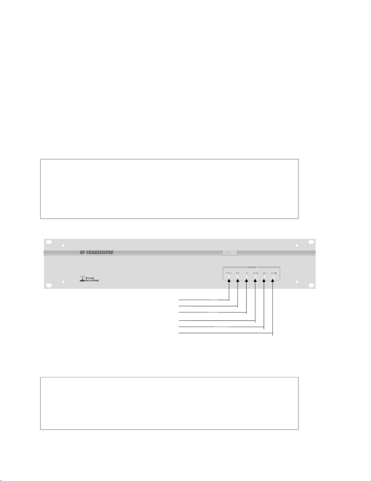
Indicators and Connectors
The SR35/50 series can be supplied with custom front panels. The standard and OEM versions are shown below.
The following tables explain the functions of the front panel LEDs. Each LED indicates the status of the SR35/50
base station in real time.
Standard Version front panel
LED FUNCTION
POWER Indicates the power supply voltage is within software selectable limits.
RX A signal is being received by the receiver or the receivers squelch is open.
TX The transmitter is transmitting RF power.
CTCSS A valid Continuous T one Coded Sque l ch Signal has been detected.
AUX Aux function is select ed or the PLL is unlocked.
ALARM A general alarm condition exists such as under / over voltage or over temperature.
LEDS: POWER
RX
TX
CTCSS
AUX
ALARM
Front panel
LED FUNCTION
POWER Indicates the power supply voltage is within software selectable limits.
RX A signal is being received by the receiver or the receivers squelch is open.
TX The transmitter is transmitting RF power.
LOW V Indicates the power supply voltage is below the software selectable limit.
LOCK The RX PLL is locked correctly or the TX is keyed and the PLL is in lock.
©RELM Communicati ons Inc. Revision 1.0
9

S Series Repeater USER MANUAL
HI TEMP Indicates the power amplifier's temperature has exceeded the software selectable
limit.
10
©RELM Communicati ons Inc. Revision 1.0
S Series Repeater USER MANUAL
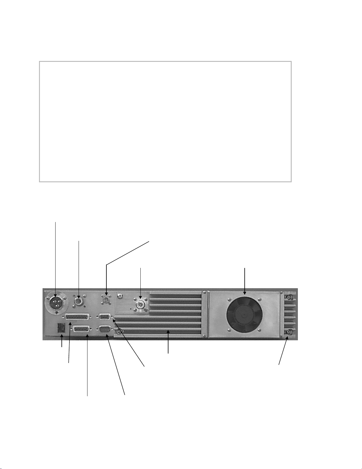
Rear Panel Connectors
CONNECTOR DESCRIPTION
DC POWER INPUT 13.8 Volt DC power input. Also +28 Volt input on spare pin.
SIMPLEX RELAY OUT OR
N TYPE RX INPUT
BNC RX INPUT Standard BNC connector for the input to the receiver for full
N TYPE TX OUTPUT The RF power output from the transmitter for full duplex operation.
SPARE RJ11 Provision for internal expansion.
DB25-F PARALLEL I/O Provides two 8 bit input ports, where one is used as the parallel
DB15 UNIVERSAL
ANALOG I/O
RS-232 SERIAL PORT 9600 Baud serial port for frequency programming, channel
SPARE DB15 Provision for internal expansion.
Location for internal simplex relay. The antenna for RX / TX
connects to this point. Else a N-Type connector can be used for the
input to the receiver for full duplex operation.
duplex operation.
BCD channel select. Also one spare 8 bit input port.
Provides the necessary analog receiver and transmitter interface for
system expansion.
selection and alarm and status monitoring.
Rear view SR35/50
DC POWER INPUT
SIMPLEX RELAY OUT
OR N TYPE RX INPUT OR BNC RXINPUT
N TYPE TX OUTPUT THERMALLY CONTROLLED FAN
SPARE
RJ11 TRANSMITTER HEATSINK
HOLE
SPARE 4 OFF SCREWS FOR
DB25-F DB15 EASY PA MODULE
PARALLEL I/O HOLE REMOVAL
DB15 UNIVERSAL RS-232
ANALOG I/O SERIAL PORT
©RELM Communicati ons Inc. Revision 1.0
11
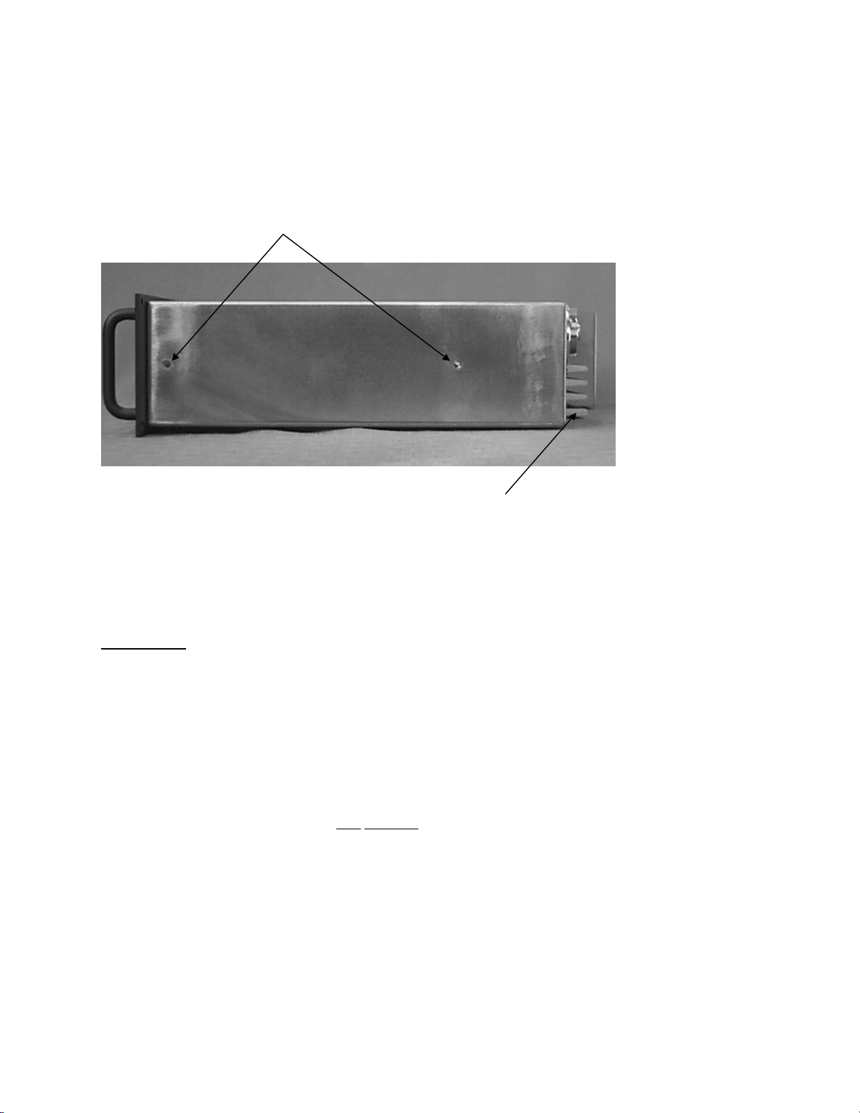
Side view SR35/50
MOUNTING HOLES FOR SLIDE-OUT RAILS
S Series Repeater USER MANUAL
THE HEATSINK AIRFLOW EXITS SIDEWAYS SO ANY NUMBER OF SR35/50
CAN BE STACKED IN A RACK ONE ABOVE THE OTHER
Installation
WARNING: Ensure that all safety precautions are observed when work ing w ith electri cal
and electronic equipment. Please contact RELM Communications if you
are in any doubt about the suitability of your test environment.
SR35/50 series radio systems are securely packed for transport in polystyrene foam peanuts, within a pasteboard
container. Before unpacking the SR35/50 radio, please inspect the packaging for signs of damage and report any
damage to your SR35/50 distributor.
Upon unpacking of the SR35/50 radio, please ensure that all items shipped were received, report any missing items
to your SR35/50 distributor. All ports on the rear of the radio should be carefully examined to ensure that packaging
has not become wedged inside them. It is very important
if any packaging causes the fan to stop working.
If you intend to install the radio in an equipment rack, consult the installation manual for your system. RELM
Communications recommends that the radio is secured i nto the rac k system using four screws through the mounting
holes in the front panel, near the handles.
to examine the fan as operation of the radio will be effected
If the radio is to be used in a stand alone configuration, ensure that it is in a secure,
dry location with sufficient air space around it to allow for adequate ventilation.
12
©RELM Communicati ons Inc. Revision 1.0
 Loading...