

RELM Communications RPU499A Users manual

Preface
Scope
This manual is intended for use by qualified technicians familiar with similar types of communication equipment. It
contains all service information and data required for the equipment.
Caution
The following precautions are recommended for personnel safety:
DO NOT transmit until all RF connectors are verified secure and all connectors are properly terminated.
SHUT OFF the power and DO NOT operate this equipment near electrical blasting caps or in a potential explosive
atmosphere.
This equipment should be serviced by qualified technicians only.
2
Brief Introduction
1
5
10
6
2
3
4
11
12
7
8
9
13
14
15
16
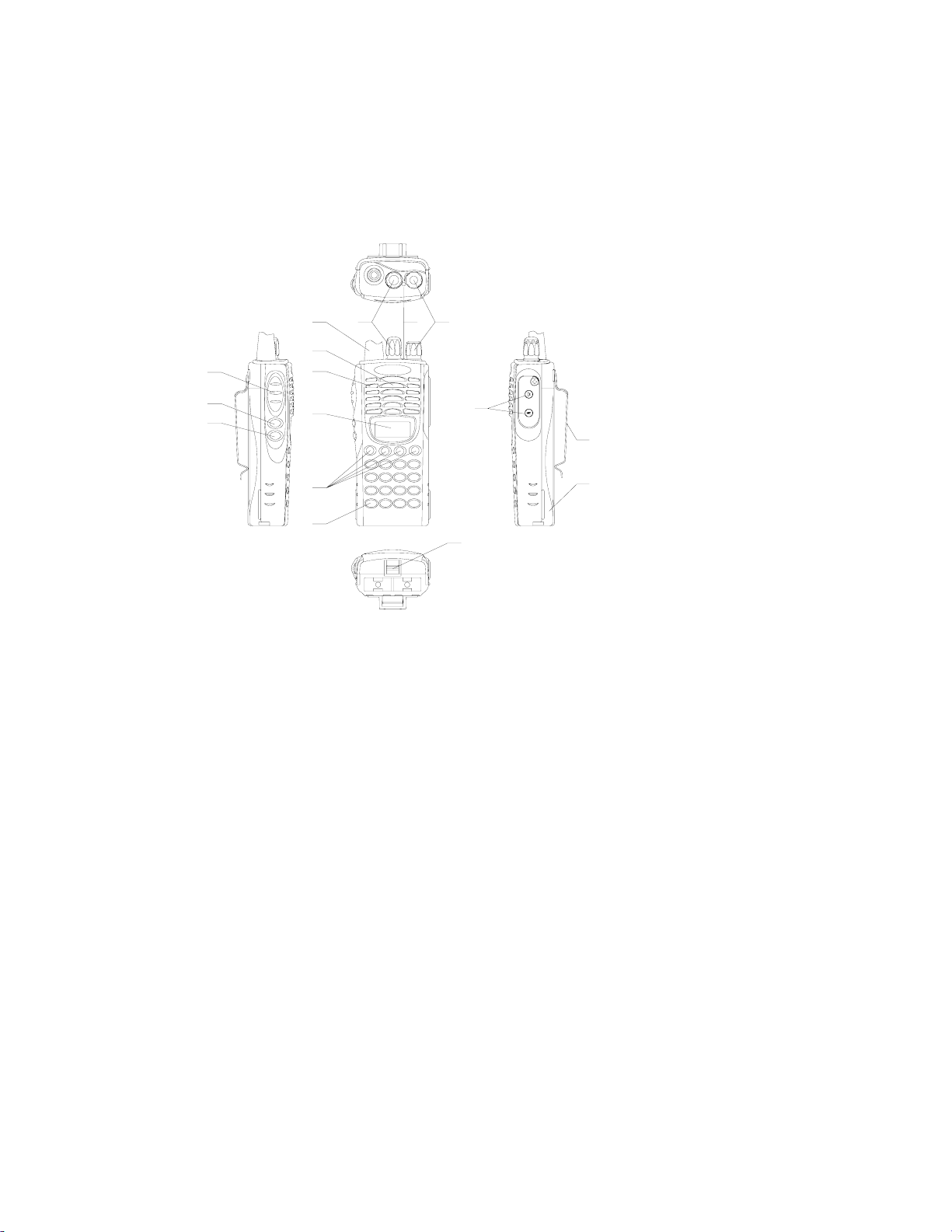
(1) ANTENNA
(2) CHANNEL SELECTOR KNOB
Used to select channel and squelch level. In addition, it can be programmed by the dealer to
delete undesired channels from scan list or to select a CTCSS frequency.
(3) LED INDICATOR
Is red when transmitting
Is green when receiving
Flashes red when the battery voltage is low and approaching the cut-off point
Flashes orange, when the radio receives proper DTMF or Two Tone decode signals.
(4) ON-OFF/VOLUME KNOB
Rotate the volume control knob clockwise to turn the unit “on” and fully counter clockwise
to turn the unit “off”. Increase or decrease volume by adjusting the volume control
accordingly.
(5) SPEAKER
(6) MICROPHONE
(7) LCD
Used to display channel and operation status.
(●,○
(8)
Used to enable auxiliary functions. Press each key to enable its corresponding function.
(9) KEYPAD
Used to enter, store or send DTMF codes.
3
■,□) PROGRAMMABLE SOFT KEYS
,
(10) PTT BUTTON
Used to switch between transmit and receive mode.
(11) LAMP BUTTON
Used to turn on/off the LCD backlight. Press the [LAMP] button, the backlight will
illuminate for about 5 seconds and then automatically turn off. Press any key other than
[LAMP] button, the timer will retime. If you press the [LAMP] button, the backlight will
light off.
(12) MONI BUTTON
Used to monitor the selected channels.
(13) EXTERNAL SPEAKER-MICROPHONE JACK
Used to connect with external speaker-microphone, programming cable, or cloning cable.
(14) BELT CLIP
(15) BATTERY
(16) BATTERY LATCH
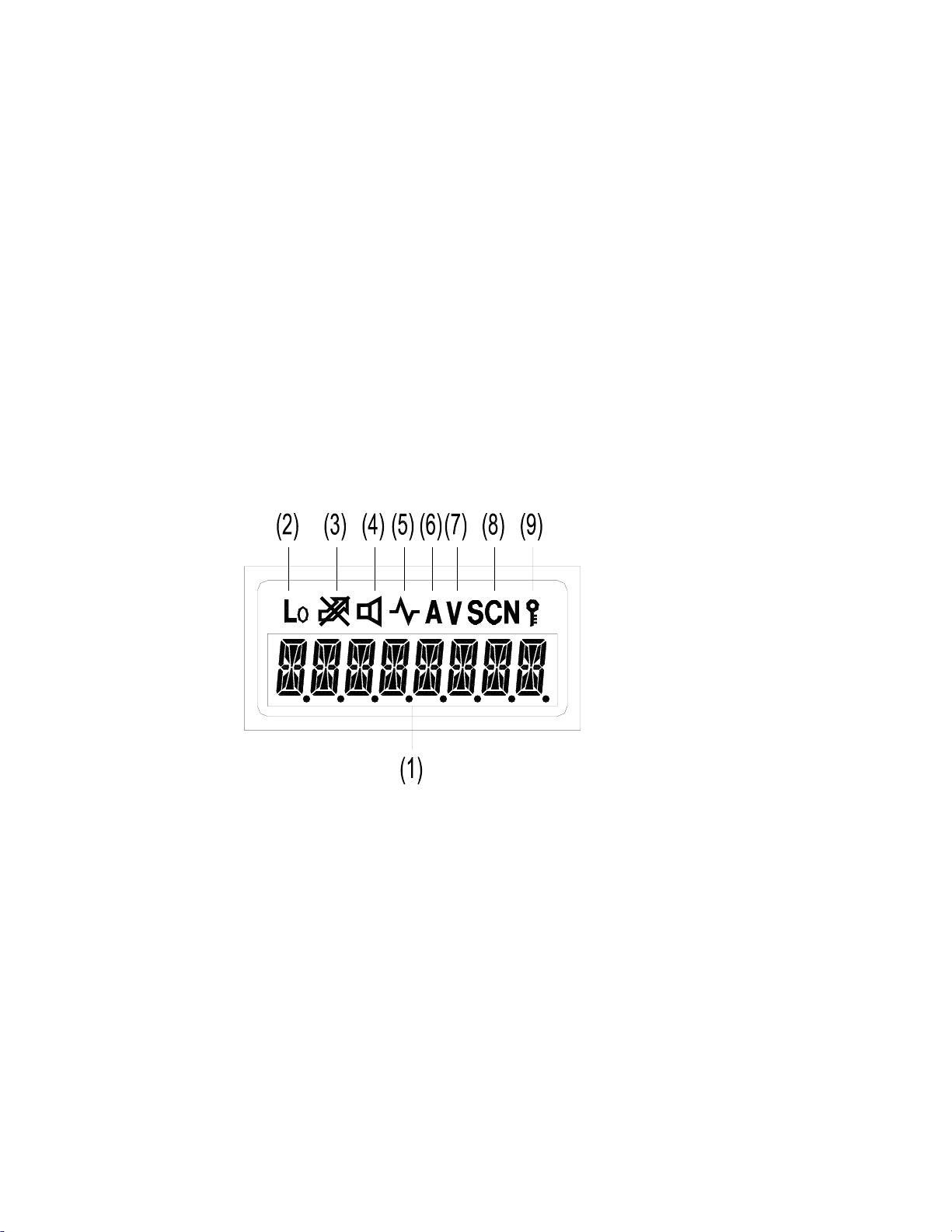
LCD
(1) Displays the selected channel number, channel frequency, channel label, squelch level or DTMF
code. When selective call is enabled, messages received are also displayed here.
Note: The “soft keys” can be programmed to toggle between display modes.
Channel Number
Channel Frequency
Channel Label– Displays characters of the channel label (up to 16 alphanumeric characters can be
programmed. Any label over 8 characters will scroll across the display).
– Displays channel number. Factory default.
– Displays the channel frequency.
(2) Appears when Low Power is selected.
(3) Appears when selected channel is busy.
(4) Appears when MONI button is pressed to disable CTCSS, CDCSS, DTMF or 2-Tone.
(5) Appears when MONI button is pressed to switch the speaker on.
(6) Appears when current channel is in the scan list. Radio only scans channels in scan list.
(7) Appears when enter number during channel label programming. Appears when CDCSS decoder
is reversed in destination set mode.
(8) Appears in scan mode.
4

(9) Appears when keypad lock is on.
5

Radio Modes
N
1. Frame of Radio Modes
Select the function you want from the modes and make the necessary settings.
DEALER MODE
TEST MODE LCD Full Screen mode
PC MODE
Conventional mode USER MODE
Self-Programming mode
Function Set Mode
DTMF Set Mode
ew Function Set
Channel Set Mode
Wired Clone Mode
Wireless Clone Mode
All Reset
Destination Set Mode
Frequency Display mode
Alignment Mode
6
2. Description of Mode Functions
MODE FUNCTION
USER MODE
DEALER MODE
Self Programming
(FUNCTION SET MODE)
Self Programming
(DTMF SET MODE)
Self Programming
(CHANNEL SET MODE)
Self Programming
(NEW FUNCTION MODE)
WIRED CLONE MODE In this mode data is copied from one radio to another through a cable.
WIRELESS CLONE MODE In this mode data is copied from one radio to another without cable by means of the DTMF
ALL RESET In this mode transmit/receive frequencies of each channel and function settings are
TEST
MODE
MENU MODE This mode is used to enter the following setting options.
ADJUSTMENT
MODE
FREQUENCY
TEST MODE
ADJUSTMENT
DATA CLONE
MODE
LCD FULL SCREEN
MODE
DESTINATION SET
MODE
Conventional mode
Dealer set the below modes:
Function set mode, DTMF set mode, Channel set mode, Wired clone mode, Wireless clone
mode, All Reset
The dealer set the following functions ON/OFF according to the user operating needs.
1.Monitor 2.Scan 3.Dial 4. Talk around 5.Low 6.Priority 7.Priority Channel 8.Look Back A
9.Look Back B 10.Revert Channel 11.TX Dwell time 12.Dropout Delay Time 13.Time out
Timer 14.Tramsmit Warning 15.TOT Rekey Time 16.TOT Reset Time 17.Squelch Level
18.BEEP 19.Signalling 20.Battery Save 21.Selectable CTCSS 22.DELETE/ADD
23.Dealer Mode-Test Mode
The dealer set the following functions ON/OFF according to the user operating needs.
24.Digit Time 25.Inter Digit Time 26.First Digit Time 27.Rise Time 28.Rise Time with
CTCSS 29.PTT ID 30.Dial ID 31.Connect ID 32.Disconnect ID 33. NO. of DTMF key
34.DTMF Hold Time 35.Store & Send 36.D key Assignment 37.DTMF Signaling
38.Intermediate Code 39.Group Code 40 SQ. Auto Reset Time
41.Call Alert/ Transpond
The dealers use this mode to set channel frequencies and signaling according to the user
operating needs.
1.Channel Selection 2.RX Frequency 3.RX Signaling 4.TX Frequency 5.TX Signaling
6.DTMF/2-Tone signaling 7.PTT ID Enable 8.Scan DEL/ADD 9.Busy Channel Lockout
10.Clock Frequency Shift 11.TX Power 12.Wide/narrow Band
13. ID Code/RX 2-Tone 14. TX 2-Tone 15. Channel Label
45.group tone 46. group tone duration 47. channel label size
48. programmable key 1
50.
programmable key 3
signal.
initialized.
This mode is for alignment of radio operation.
This mode is for checking the frequencies and repairing the radio.
This mode is used to clone adjustment data from one radio to another.
All characters and signs on the LCD are displayed.
This mode sets radio destination.
[●] 49.
[■] 51. p
programmable key 2
rogrammable key 4
[○]
[□]
3. Keypad Entry for Mode Startup
7
USER
MODE
DEALER
MODE
MODE Key Remarks
Conventional Mode POWER ON Turn on the power to enter Conventional Mode
While holding down [LAMP] and
Function Set Mode
DTMF Set Mode As above
Channel Set Mode As above
New function set
mode
Wired Clone Mode As above Press [LAMP] to enter Wired Clone Mode.
Wireless Clone
Mode
[○]
key simultaneously, turn on the
power (in 2 seconds)
As above
As above Press [MONI] to enter Wireless Clone Mode.
Press
Press
Press
Press
[●]
key to enter Function Set Mode.
[○]
key to enter DTMF Set Mode.
[■]
key to enter Channel Set Mode.
[□]
key to enter New Function Set Mode.
TEST
MODE
All Reset As above
While holding down [LAMP] and
Menu Mode
Adjustment Mode Select “ADJUST” in menu mode.
Frequency Test
Mode
Adjustment Data
Clone Mode
LCD Full Screen
Mode
Destination Set
Mode
[■]
key simultaneously, turn on the
power (in 2 seconds).
Select “FREQ TST” in menu mode.
Select “TUNE CLN” in menu mode.
Select “FULL LCD” in menu mode.
Select “DEST SET” in menu mode.
[□]
Press
Press
return to Menu Mode.
Press
key and [PTT] simultaneously.
[□]
key to enter test mode and
[□]
key to enter the mode and
[■]
key to
[■]
key to exit.
Prohibit entering dealer mode and test mode
Dealer mode and test mode can be prohibited by programming to prevent users from changing the parameters with self-
programming feature or with external programmer.
Cancel the Prohibit
Short the dealer mode control point and the test mode control point and then the prohibit will be cancelled at
POWER-ON. Or use the programming software to cancel.
Note:
The dealer mode control point and the test mode control point locate over LCD and marked with SELF.
DEALER MODE
Self-Programming (Function Setting)
1. Turn on the power while pressing [LAMP] and
appears on LCD.
Note: please refer to the notes of self-programming mode.
2. In dealer mode, press
[●]
key to enter function set mode.
3. Use Channel Selector knob to set functions ON or OFF or to select the setting.
4. After a function is set, press [PTT] to store the setting and the menu goes to the next function option.
8
[○]
, in 2 seconds the radio enters the dealer mode, and “SEL”
key
5. Press
[●]
key to return to Dealer Mode from current option, and the current data shown on the display will not be
stored.
6. Press [PTT] to store current function setting and a beep will sound to confirm the action.
7. END appears when settings in function mode are completed.
Function
No.
1 MONITOR
Function
Name
2 SCAN
3 [DIAL]
TALK
4
AROUND
5 [LO]
6 PRIORITY
PRIORITY
7
CHANNEL
LOOK BACK A 0.3s ~1.5s 0.5s
8
LOOK BACK B 0.5s ~ 5.0s 2.0s
9
REVERT
10
CHANNEL
Settings (Defaults are
underlined)
OFF
Monitor Momentary MONI 1
Monitor Lock MONI 2
SQ OFF
Momentary
OFF SCAN OFF Invalid
CO SCAN CO “Carrier Operated” function
TO SCAN TO “Time Operated” function
Disable DIAL OFF Disables the [DIAL] key.
Enable
Disable TARE OFF Invalid
Talk Around TARE TA “Talk around” function is enabled
Reverse TARE RE “ Frequency Reverse” function is enabled
Disable LO OFF Disables [LO] key.
Enable
OFF
Fixed PRIO FIX Fixed priority channel
Selected PRIO SEL Variable priority channel
1 ~ 99 1
(0.1s/1STEP)
(0.5s/1STEP)
Selected
Last Call REV LSTC
Last Used REV LSTU
Selected + Talk Back
Priority REV PRIO Priority channel
Display Remarks
MONI OFF Invalid
Signaling squelch is temporarily disabled while [MONI]
button is held down.
Signaling squelch is temporarily disabled while [MONI]
button is pressed. Each time press can toggle between
squelch disable and enable.
MONI 3 Squelch is disabled while [MONI] button is held down.
DIAL ON Enables the [DIAL] key.
LO ON
PRIO OFF NO priority setting
PRICH 1
PRICH 99
LBA 300
LBA 1500
LBB 500
REV SEL Channel where scan starts.
SEL TALK
Enables [LO] key.
Priority channel
(Only valid when “fixed priority” is enabled)
The period time between radio back scanning a priority
channel from a normal channel when there is no activity
on priority channel
The period time between radio back scanning a priority
channel from a normal channel when there is activity on
priority channel but not matching its signaling.
During scanning, it’s the latest channel at pause; during
scan stopping, it’s the channel stopped; if scan never
stops, it’s the start channel.
During scanning, it’s the latest transmit channel; during
scan stopping, it’s the channel stopped; if scan never
stops, it’s the start channel.
During scanning, it’s the start channel; during scan
stopping, it’s the channel stopped.
Priority + Talk Back PRI TALK
TX-SCAN
11
DWELL
TIME
DROP OUT
12
DELAY TIME
DODT 5.0
9
0.5s ~ 5.0s 3.0s
(0.5s/1STEP)
0.5s ~ 5.0s 3.0s
(0.5s/1STEP)
TSDT 0.5
TSDT 5.0
DODT 0.5
During scanning, it’s the priority channel; when scan
stopping, it’s the channel stopped.
Duration before scan restarts when it stops by
transmission.
Duration before scan restarts when it stops by signal
input.
TIME OUT
13
TIMER
TOT ALERT
14
TIME
TOT REKEY
15
TIME
TOT RESET
16
TIME
SQUELCH
17
LEVEL
SQL 9
18 BEEP NO BEEP OFF No beep tone
YES BEEP ON Beep tone sounds
19 SIGNALING AND SGNL AND Squelch is opened when both match.
OR SGNL OR Squelch is opened when either matches.
BATTERY
20
SAVE
Enable BATT ON Battery Save function.
SELECTABLE
21
CTCSS
Enable VQT ON Permit Selectable CTCSS
DELETE/
22
ADD
ENABLE
Enable SADD ON Permit Delete/Add
DEALER
23
MODE/ TEST
MODE
ENABLE
Enable MODE ON
END END
OFF 30s~300s 60s
(30s/1STEP)
OFF
1 ~ 60
(10s/1STEP)
OFF 1s ~ 60s OFF
(1s/1STEP)
OFF 1s ~15s OFF
(1s/1STEP)
0 ~9 5
(1s/1STEP)
Disable BATT OFF No Battery Save function.
Disable VQT OFF Prohibit Selectable CTCSS
Disable SADD OFF Prohibit Delete/Add
Disable MODE OFF Prohibit dealer mode and test mode
TOT OFF
TOT 30
TOT 300
TOTA OFF TOT off.
TOTA 1
TOTA 60
TOTK OFF
TOTK 1
TOTK 60
TOTS OFF TOT is immediately reset after transmission stops.
TOTS 1
TOTS 15
SQL 0
When OFF, in order to protect power amplifier, max. time
of continuous transmission is set as 10 minutes.
Maxi. time of continuous transmission
When this feature is enabled, the radio will call an
alert at the set time. Transmission will be prohibited
by TOT after this time.
Duration until transmission is allowed after radio
returning to receive mode by TOT.
Transmit prohibited until preset time elapses.
TOT won’t reset until preset time elapses, even if
transmission has stopped.
Squelch level is set higher (tighter), as the figure
increases.
Permit dealer mode and test mode
When END is displayed, press [PTT] to return to Function Setting.
Note:
LOOK BACK: When radio is scanning a non-priority channel, the status of the priority channel will be detected
periodically. The time interval for this detecting is as the following:
A is period when there is no activity on the priority channel.
B is period when there is activity on the priority channel, however not matching its signaling.
Self-Programming (DTMF setting)
1. Turn on the power while pressing [LAMP] and
mode.
10
[○]
key simultaneously, and in 2 seconds the radio enters the dealer
 Loading...