

Page 1

1
THANK YOU!
Thank you for your purchase of RELM mobile radio RM-800. We believe this
easy-to-use radio will provide you with dependable and reliable
communications at peak efficiency. Please read this manual carefully before
use. The information presented herein will help you to derive maximum
performance from your radio.
MODELS COVERED IN THIS MANUAL
RMV800 Mobile Radio
RMU800A Mobile Radio
Page 2
2
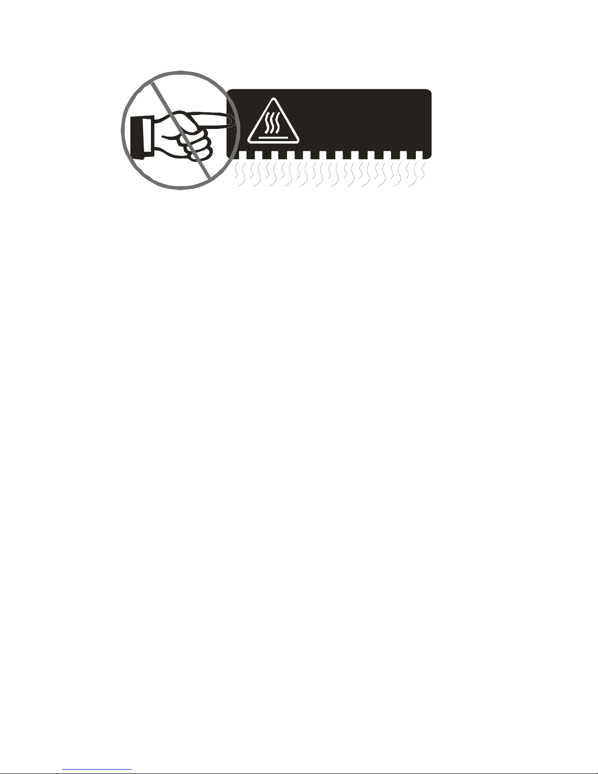
HOT SURFACE
Avoid contact during prolonged use
Do not touch the metal surface of the radio while it is in use.
Do not mount the radio such that the chassis can come in contact with skin.
High temperatures may burn you skin.
MANDATORY SAFETY INSTRUCTIONS TO INSTALLERS AND USERS
----------------------------------------------------------------
? Use Only manufacturer or dealer supplied antennas.
? Antenna minimum safe distance: 82cm (32 inches).
? Antenna used for this transmitter must not exceed an antenna gain of 5.5dBi (for
RMV800) and 3dBi (for RMU800A).
The FCC (Federal Communications Commission) has adopted a safety standard for
human exposure to RF energy which is below the OSHA (Occupational Safety and Health
Act) limits.
? Antenna mounting: The antenna supplied by the manufacturer or radio dealer must not
be mounted at a location such that during radio transmission, any person can come
closer than the above indicated minimum safe distance to the antenna (i.e.
82cm/32inches).
? To comply with current FCC RF Exposure limitations, the antenna must be installed at
or exceeding the minimum safe distance indicated above, and in accordance with the
requirements of the antenna manufacturer or supplier.
? Vehicle installation: The antenna can be mounted at the center of a vehicle metal roof or
trunk lid if the minimum safe distance is observed.
Antenna substitution: Don’t substitute any antenna for the one supplied or recommended
Page 3

3
by the manufacturer or radio dealer. You may be exposing person(s) to excessive radio
frequency radiation. You may contact your radio dealer or the manufacturer for further
instructions.
Warning
Maintain a separation distance from the antenna to person(s) at least 82cm (32inches).
“This transmitter is authorized to operate with a maximum duty factor of 50%, in a typical
push-to-talk mode, for satisfying FCC RF exposure compliance requirements.”
Page 4

4
Contents
Caution
MANDATORY SAFETY INSTRUCTIONS
User Safety, Training, and General Information
Compliance with RF Energy Exposure Standards
FCC Compliance
Precautions
Product Inspection
Radio Installation and Warnings
Radio Overview
Basic Operations
Turn the Radio On/Off
Adjust the Volume
Monitor
Select a Channel
Select a Zone
Receive
Transmit
Selectable Power Level
Beginning / End of Transmission ID
Channel Scan
Busy Channel Lockout (BCL)
BCL Override
DTMF Call
Code Squelch
Time-Out-Timer (TOT)
Emergency Call
Stun
Programmable Auxiliary Functions
Reverse Frequency
Talkaround
Selectable Squelch Level
User Selectable Tone (UST)
Public Address
Dual Home Channels
Horn Alert
Selectable 2-Tone Encode
Selectable 5-Tone Encode
Page 5

5
Display Frequency
Display Label
Display Mode
LCD Backlight
Compander
Scrambler
Short Message
GPS Report
Optional Signalling
User Set Mode
Appendix 1 Entering Characters
Optional Accessories
Page 6

6
User Safety, Training, and General Information
READ THIS IMPORTANT INFORMATION ON SAFE AND EFFICIENT OPERATION
BEFORE USING YOUR RELM MOBILE RADIO.
n Compliance with RF Energy Exposure Standards
Your RELM mobile radio is designed and tested to comply with a number of national and
international standards and guidelines (listed below) regarding human exposure to radio
frequency electromagnetic energy. This radio complies with the IEEE and ICNIRP
exposure limits for occupational/controlled RF exposure environment at operating duty
factors of up to 50% transmitting and is authorized by the FCC for occupational use only.
In terms of measuring RF energy for compliance with the FCC exposure guidelines, your
radio radiates measurable RF energy only while it is transmitting (during talking), not
when it is receiving (listening) or in standby mode.
Your RELM mobile radio complies with the following of RF energy exposur
e standards and guidelines:
l United States Federal Communications Commission, Code of Federal
Regulations; 47CFR part 2 sub-part J
l American National Standards Institute (ANSI)/Institute of Electrical and
Electronic Engineers (IEEE) C95. 1-1992
l Institute of Electrical and Electronic Engineers (IEEE) C95. 1-1999 Edition
l International Commission on Non-Ionizing Radiation Protection (ICNIRP) 1998
??Operational Instructions and Training Guidelines
To ensure optimal performance and compliance with the occupational/controlled
environment RF energy exposure limits in the above standards and guidelines, users
should transmit no more than 50% of the time and always adhere to the following
procedures:
Transmit and Receive
To transmit (talk), push the Push-To-Talk (PTT) button; to receive, release the PTT button.
Page 7

7
Approved Accessories
For a list of RELM approved accessories, see the accessories page of this user manual
or visit the following website which lists approved accessories: http://www.RELM.com.
n FCC Compliance
Part 15 Compliance
This equipment has been tested and found to comply with the limits for a Class B digital
device, pursuant to part 15 of the FCC Rules. These limits are designed to provide
reasonable protection against harmful interference in a residential installation. This
equipment generates, uses and can radiate radio frequency energy and, if not installed
and used in accordance with the instructions, may cause harmful interference to radio
communications. However, there is no guarantee that interference will not occur in a
particular installation. If this equipment does cause harmful interference to radio or
television reception, which can be determined by turning the equipment off and on, the
user is encouraged to try to correct the interference by one or more of the following
measures:
? Reorient or relocate the receiving antenna.
? Increase the separation between the equipment and receiver.
? Connect the equipment into an outlet on a circuit different from that to which the
receiver is connected.
? Consult the dealer or an experienced radio/TV technician for help.
FCC Licensing Requirements
Your radio must be properly licensed Federal Communications Commission prior to use.
Your RELM Wireless dealer can assist you in meeting these requirements. Your dealer
will program each radio with your authorized frequencies, signalling codes, etc., and will
be there to meet your communications needs as your system expands.
Precautions
General Safety Standards
* Do not attempt to configure the radio while driving; it is too dangerous.
* Do not operate your radio when someone is either touching the antenna or standing
within 2 or 3 feet of it, to avoid the possibility of radio frequency burns or related
physical injury.
* Do not operate the radio near dynamite blasting caps or in an explosive atmosphere.
Page 8

8
* Switch OFF the radio while refueling or parking at gas station.
* Turn off your radio in any place where posted notices instruct you to do so.
* Do not modify the radio for any reason.
* Do not expose the radio to direct sunlight over a long time, nor place it close to heating
source.
* Do not place the radio in excessively dusty, humid areas, nor on unstable surfaces.
* Refer service to qualified technicians only.
Operation Safety Guidelines
* For vehicles equipped with electronic anti-skid braking systems, electronic ignition
systems or electronic fuel injection systems, interferences may occur during the radio
transmission. If the foregoing electronic equipments are installed on your vehicle,
please contact your dealer for further assistance to make sure that the radio
transmission will not interfere with these equipments.
* For radio installation in vehicles fueled by LP gas with LP gas container within interior of
the vehicles, the following precautions are recommended for personal safety.
(1) Any space containing radio equipment shall be isolated by a seal from the space in
which the LP gas container and its fittings are located.
(2) Remote (outside) fitting connections shall be used.
(3) Good ventilation is required for the container space.
Safety: It is important that the operator is aware of, and understands, hazards common
to the operation of any radio.
Installation Safety Guidelines
* Do not mount the mobile radio overhead or on a sidewall unless you take special
precautions.
* If someone were to remove the radio and fail to replace it properly, road shock could bump
the radio loose, and the falling radio could, in some circumstances, cause serious injury
to the driver or a passenger. In a crash, even when properly installed, the radio could
break loose and become a dangerous projectile.
Page 9

9
Product Inspection
Please carefully unpack the radio. Before use, it is recommended that you inspect the
product as follows.
First check the shipping carton for any signs of damage. Confirm the supplied product
against the packing slip to assure accuracy. If any items are missing or have been
damaged during shipment, please file a claim to the carrier immediately.
Supplied Accessories
Item Quantity (pcs)
DC Power Cable 1
Mounting Bracket 1
Microphone 1
Microphone Hanger 1
Screw Set 6
Fuse 2
Owner’s Manual 1
Remote Speaker Microphone SM07R2 & coil cord
Microphone Hanger
Mounting Bracket
Adjustment Knobs
Screw Set
Power Cable
Fuse
Page 10
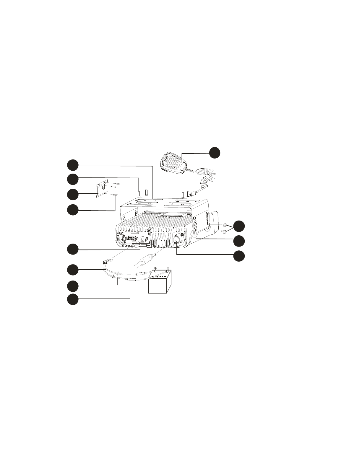
Radio Installation
1
9
¦ Installing the Radio
1. Attach the mounting bracket, using the 4.8 x 20mm self-tapping screws, in a location
where convenient operation is accessible.
2. Connect the antenna and the supplied power cable to the radio.
3. Slide the radio into the mounting bracket and secure it using the Adjustment screws.
4. Mount the microphone hanger, using the 4 x 16mm self-tapping screws, in a location
where it will be within easy reach of the user.
5. Connect the microphone plug to the microphone jack on the front panel of the radio,
then place the microphone on the hanger.
2
3
4
5
6
7
8
Fig. 1 Radio Set Connection Detail
1. Remote speaker microphone
2. Mounting bracket
3. 4.8 × 20 mm Self-tapping screw
4. Microphone hanger
5. 4 × 16 mm Self-tapping screw
6. Power inlet
7. Red lead
8. Black lead
9. Fuse
10. Antenna connector
11. Main unit
12. Adjustment knob
12
11
10
10
Page 11

¦ Installation Tools
The following tools are required for proper installation of your radio:
l Electric drill: ¢6mm or above
l Cross head Screwdriver
Cross head screwdriver (used to fix 4.8 × 20mm self-tapping screw)
¦ Warnings:
1. The radio operates in 13.6 ± 15% V negative ground systems only. Check the voltage
and polarity of the power supply on the vehicle before installation.
2. Be sure to check how far the screw will extend below the radio surface to avoid
damage to the auto wiring or auto parts when drilling mounting holes.
3. Connect the radio with the supplied antenna and power cable before installing the
radio by the mounting bracket.
4. Install the radio securely using the supplied mounting bracket to make sure that the
radio will not loosen in the event of accidents. The loose radio may cause injury to the
passenger.
5. Arrange the installation location of the radio to make sure that the control unit in the
front panel is convenient for operation.
6. Be sure to determine the location of the installing holes before installation and drilling.
7. Be sure to make room at the rear of the radio for power cable connection.
8. When replacing the fuse in the DC power cable, be sure to replace it with a fuse of
the same value. Never replace a fuse with one that has a higher value.
11
Page 12
Radio Overview
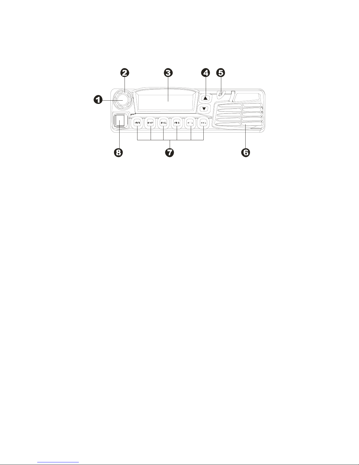
¦ Front Panel View
? Power Switch
Press to switch the radio on/off.
? Selector Knob
Volume Up/Down, Channel Up/Down, Zone Up/Down features can be programmed to
this knob (set by your dealer).
Turn the knob clockwise to adjust upwards and counterclockwise to adjust downwards.
? LCD Display
Please refer to “LCD Display” section.
? Up/Down Key
Volume Up/Down, Channel Up/Down, Zone Up/Down features can be programmed to the
keys (set by your dealer).
? LED Indicator
? Speaker
? Programmable Function Key (PF1-PF6)
Your dealer can program these keys as shortcuts to various radio features.
Please refer to “Programmable Function Key” section.
? Microphone Jack
Insert the microphone plug into this jack.
¦ LED Indicator
The LED indicator
l glow red while transmitting
l glow green while receiving
l flash orange when receiving code squelch, selective call, the matching
2-Tone/5-Tone or DTMF signaling
12
Page 13
¦ LCD Display
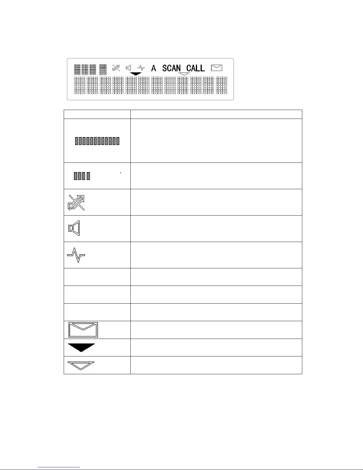
Indicator Description
1. Display zone / channel number.
2. Display zone / channel label (set by your dealer, up to 12
alphanumeric characters).
3. Display channel Frequency
4. Display the preprogrammed functions
1. Display zone / channel number.
2. Display transmit power level (H, M or L).
3. Display the preprogrammed functions
Appears when the selected channel is busy.
Appears when [MONI] key is pressed to disable CTCSS,
CDCSS, DTMF or 2-Tone/5-Tone.
A
SCAN
CALL
Appears when [MONI] key is pressed to switch the speaker on.
1. Indicate second development feature.
2. Appears when the auxiliary function is activated.
Appears while scanning.
Appears when transmitting a selective call.
Appears when a new message is received.
Appears when the selected zone is in the scan list.
Appears when the selected channel is in the scan list.
13
Page 14

Programmable Function Key
PF1-PF6 key can be programmed with the following auxiliary functions:
1. Off
2. VOL UP
3. VOL Down
4. CH Up
5. CH Down
6. Zone Up
7. Zone Down
8. MoniA
9. MoniB
10. MoniC
11. MoniD
12. DLabel
13. Dfreq
14. Dmode
15. UserTone
16. Sel2Tone
17. Sel5Tone
18. Sel HDC
19. TXPower
20. Scan
21. Scan Add/Del
22. Reverse
23. TA
24. SELSQL
25. HomeCH
26. PA
27. HornAlert
28. LCDBL
29. Scramble
30. Compand
31. AUX A
32. AUX B
33. Send GPS
34. Emergency
35. Message
14
Page 15
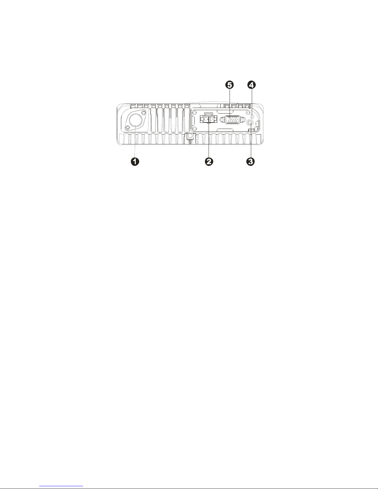
¦ Rear Panel View
? Antenna Connector
Used to connect external antenna.
? Power inlet Connector
Adopt RELM-authorized DC power cable and 13.6 V input AC power.
? Speaker Jack
Used to connect external speaker and only available for the plug of 3.5 mm.
? GPS Antenna Jack
? 15 Pin Connector (for accessories)
15
Page 16

Basic Operations
Turn the Radio On/Off
Press the Power switch to switch the radio on.
Press and hold the Power switch for approximately 1 second to switch the radio off.
If Power on Password is set to protect your radio, “Chk P” and the cursor will appear on
the display when power is turned on. You can unlock the radio by entering the correct
password (8 digits maximum):
1. Select a digit (0-9) by rotating the selector knob.
If you are using an optional microphone with a keypad, you can also enter the
password by pressing the appropriate keypad keys.
2. Press the [PF3] / [PF4] key to move cursor forward and backward.
This step can be skipped when using the keypad.
3. Repeat steps 1 and 2 to enter the entire password.
4. Press the [PF6] key or the [PTT] key to complete the entry.
Adjust the Volume
Selector Knob, [? ] / [? ] or the function keys PF1-PF6 can be programmed with VOL Up /
VOL Down features to adjust volume level.
Rotate the Selector Knob clockwise or press the key which be programmed as [VOL Up]
key to increase the volume; rotate the knob counter-clockwise or press the key which be
programmed as [VOL Down] key to decrease the volume. The current volume level is
displayed on the LCD. The LCD returns to original display mode in 5 seconds. Press any
key to exit from the volume level display mode.
Monitor
If monitor feature is set by your dealer, press the key programmed as [MONI] in receive
mode to monitor activity on your selected channel.
Your dealer can select one of the following four modes for monitor feature:
l Monitor Unmute-Momentary
Hold down the [MONI] key to open CTCSS/CDCSS/DTMF/2-Tone/5-Tone signalling
squelch. Release to close the signalling squelch.
l Monitor Unmute-Toggle
Press the [MONI] key to open CTCSS/CDCSS/DTMF/2-Tone/5-Tone signalling
squelch. Press again to close the signalling squelch.
l Carrier Squelch-Momentary
Hold down the [MONI] key to open carrier squelch; Release to close the carrier
squelch.
l Carrier Squelch-Toggle
Press the [MONI] key to open carrier squelch. Press again to close the carrier
squelch.
16
Page 17

Select a Channel
Selector Knob, [? ] / [? ] or the function keys PF1-PF6 can be programmed with CH Up/
CH Down features to select a channel. Transmit/Receive frequencies of the channel are
set by your dealer.
Rotate the Selector Knob clockwise or press the key which be programmed as [CH Up]
key to select a channel upwards; Turn the knob counterclockwise or press the key which
be programmed as [CH Down] key to select downwards.
Select a Zone
Selector Knob, [? ] / [? ] or the function keys PF1-PF6 can be programmed with Zone Up/
Zone Down features to select a zone. Transmit/Receive frequencies of the channel are
set by your dealer.
Rotate the Selector Knob clockwise or press the key which be programmed as [Zone Up]
key to select a zone upwards; Turn the knob counterclockwise or press the key which be
programmed as [Zone Down] key to select downwards.
Receive
If your dealer has programmed CTCSS/CDCSS/DTMF/2-Tone/5-Tone signalling on the
selected channel, you will hear calls only when the matching code or tone is received;
otherwise, all calls on the same channel can be heard.
Transmit
1. Press the key programmed as [MONI] to make sure that the selected channel is not in
use.
2. Hold down the [PTT] key.
3. Dial a DTMF number using the microphone keypad.
Step 3 is not necessary all the time.
4. Speak into the microphone with normal voice. The LED glows red during
transmission.
5. Release the [PTT] key to receive.
6. When your conversation is finished, return the microphone to its hanger.
Selectable Power Level
If transmit power (programmed by your dealer) is set to “high” (or "middle”) on any given
channel, press the key programmed as [TX Power] to toggle the TX power among high,
middle and low. The current power level is indicated by “H” /“M” / “L” icon on the LCD.
Since low power helps to conserve battery power and reduce the risk of interfering with
others, you are recommended to select low power when communication quality is
guaranteed.
17
Page 18

Notes:
? Press the [TX Power] key while using a channel programmed with low power, an error
tone will sound and the transmit power will not change.
? When changing a channel from high/middle power to low power, all other channels
programmed with high/middle power will change to low power accordingly.
Beginning/End of Transmission ID Signal
The radio can be programmed to send Beginning/End of Transmission ID when
accessing / releasing repeaters or telephone systems. The ID signal includes DTMF and
5-Tone types. Two modes can be configured:
? Press the [PTT] key to send a Beginning of Transmission ID Signal; Release the [PTT]
key to send an End of Transmission ID Signal.
? Press [*] while holding down the [PTT] key to send a Beginning of Transmission ID
Signal; press [#] while holding down the [PTT] key to send an End of Transmission ID
Signal (for DTMF type only).
Channel Scan
? Scan Types
? Single Zone Scan
All channels in the current zone that have been added to the scan list can be scanned.
? Multi Zone Scan
All channels within all the zones that have been added to the scan list can be scanned.
? List Zone Scan
The radio only scans the channels within the specified range of zones that have been
added to the scan list. Individually each zone is assigned with a scan list, which provides
quick recognition of the zones to be locked out of scan list.
Note: Scan list for each zone can be added/ deleted.
? Scan Start
Press the key programmed as [SCN], scan starts from the current channel and ascends
through the channel numbers in scan list. “SCAN” appears on the LCD (“-SCAN X -” in
List Zone Scan mode, “X” is the current list number).
Note: Scan function can be used only when two or more channels are in the scan list.
? Scan Stop
1. Press the [SCN] key again to stop scanning. “SCAN” disappears on the LCD.
2. Activate the Monitor function.
3. Carrier is detected on channels where no signalling is set.
4. Carrier is detected on channels where signalling is set, and the matching signalling is
received.
18
Page 19

? Scan Restart
When the radio stops on a busy channel, scanning can be restarted according to the
restart mode, which can be programmed by the dealer as carrier-operated scan or
time-operated scan.
? Carrier Operated Scan
Scanning remains on an active channel until there are no activities; while the channel is
free, the radio remains on the channel for the programmed Dropout Delay Time
(programmed by your dealer) before it resumes scanning.
? Time Operated Scan
Scanning remains on the active channel for only the programmed Dropout Delay Time
(programmed by your dealer) before it resumes scanning. After the expiration of
Dropout Delay Time, the radio will begin scanning other channels even if the channel
is still busy.
? Dual Priority Scan
If your dealer has programmed dual priority channels, the radio will periodically detect the
activity on priority channels while stopping on non-priority channels. When any activity is
detected on the priority channels, the radio will switch to the priority channels for
communications.
“P1” appears on the LCD when the channel is set as Priority 1, “P2” appears when set as
Priority2, and “PP” when set as both Priority 1 and Priority 2.
? Operator Selectable Priority Channel
If priority channel is programmed by your dealer as “Operator Selectable”, you can set the
current channel as priority or non-priority channel:
Press the key programmed as [MONI] twice while holding down the key programmed as
[SCN], the current channel is changed to "Priority 2".
Press the [MONI] key three times while holding down the [SCN] key, the current channel
is changed to "Priority 1".
Press the [MONI] key four times while holding down the [SCN] key, the current channel
restores to original setting.
? Scan Add/Delete
This feature allows you to add/delete a channel to/from the scan list in the non-scan
mode.
1. Select the channels to be added/ deleted by using the channel selector knob.
2. Press the key programmed as [Add/Del] to toggle between ADD and DELETE.
“ ”appears on the LCD when a channel is added.
Note: The radio only scans the channels that have been added to the scan list.
? Look Back Temporary Disable
When scanning looks back and stops on a priority channel, press the key programmed as
[Add/Del] to deactivate the Look Back function.
19
Page 20

? Nuisance Channel Temporary Delete
This feature allows you to temporarily delete a channel to/from the scan list during
scanning.
When scanning stops on an undesired channel (e.g. nuisance channel), press the key
programmed as [Add/Del], the channel is temporarily removed from the scan list and
scanning resumes.
Note: The deletion of channels are not saved when radio exits from the scan mode.
? Revert Channel
Press the [PTT] key during scanning, the radio will stop scanning and switch to the preset
revert channel (programmed by your dealer) for transmission.
? Off Hook Scan
If your dealer has programmed Off Hook Scan feature, scanning is not controlled by
microphone hook status, it also means that the radio always scans, and stops by signal
presence. Otherwise, microphone must be on hook for scanning.
Busy Channel Lockout (BCL)
When activated by your dealer, the BCL feature will prevent you from talking on a channel
that is already in use. Press the [PTT] key while the channel is in use, the radio will emit
an alert tone and transmission will be inhibited. Release the [PTT] key to stop the alert
tone. Wait until the channel is not in use before you try to transmit again.
BCL Override
If BCL Override feature is activated, you can override the BCL feature and transmit on a
busy channel. To override the BCL, release the [PTT] key when the alert tone sounds,
then press the [PTT] key again within 0.5 second.
DTMF Call
? Manual Dial
Hold down the [PTT] key, then enter the DTMF number by pressing the keys ([0] ~ [9], [*],
[#]) on optional microphone keypad. Audible tone sounds when corresponding DTMF
tone is transmitted.
The radio can be programmed by your dealer to remain in transmit mode for 2 seconds
after releasing the [PTT] key. Press any numeric key within 2 seconds to continue
transmission.
? Keypad Auto PTT
If this feature is programmed by your dealer, you can transmit a DTMF tone by pressing
the keys on optional microphone keypad without holding down the [PTT] key.
? Store & Send
20
Page 21

If this feature is activated, enter a preset DTMF number (16 digits maximum) in receive
mode, then press the [PTT] key to place the call. The DTMF number scrolls across the
LCD display as it is entered, and its corresponding audible tone sounds.
Notes:
? If you enter a wrong digit or decide not to dial the number, press any key other than the
power switch on the front panel to exit.
? The [D] key can be programmed by your dealer as a null tone. This also means that “D”
tone is not transmitted when “D” is entered. Instead, “D” is used for a pause time
(programmable by your dealer).
? Dial Speed
Your dealer can select dial speed at 6, 8, 10 or 15 digits per second.
This is designed to reduce false decoder operation by providing a fixed time period
between digits. Default: 10 digits per second
? Store DTMF Numbers
You can store DTMF numbers (16 digits maximum) in each of the 32 Auto Dial memory
locations (01~ 32).
1. Press the [#] key, “D----------” appears on the LCD.
2. Enter the DTMF number (16 digits maximum).
You can enter the digits 0-9, A-F.
To enter A,B,C,D,E,F, hold down the [PTT] key, then enter 2, 5, 8, 0, *, # respectively.
3. Press the [#] key, “------” appears on the LCD indicating the memory location.
4. Enter the desired memory location number (01~ 32).
5. Press the [#] key again to store the DTMF number into the memory location.
If you enter a wrong digit or decide not to dial the number, press any key other than the
power switch on the front panel to exit.
? Confirm Stored DTMF Numbers
1. Press the [*] key, “A---” appears on the LCD.
2. Enter the desired memory location number (01~ 32).
The stored DTMF number or caller ID is displayed on the LCD. Press any key other
than the [PTT] key, the original display is restored.
? Dial Stored DTMF Numbers
1. Press the [*] key, “A---” appears on the LCD.
2. Enter the desired memory location number (01~ 32).
The stored DTMF number or caller ID is displayed on the LCD.
3. Press the [PTT] key to place the call.
? Clear Stored DTMF Numbers
1. Press the [#] key, “D----------” appears on the LCD.
2. Press the [#] key again, “D Clear” appears on the LCD.
3. Enter the desired memory location number (01~ 32).
21
Page 22

To cancel the process, press any key other than [0]~ [9].
4. Press the [#] key, the stored DTMF number is cleared.
? Redial
1. Press the [*] key, “A--” appears on the LCD.
2. Press the [0] key twice, the last number (16 digits maximum) you dialed is redialed.
The redialed number is displayed on the LCD.
3. Press the [PTT] key to place the call.
Note: The redial memory is cleared when the radio is turned off.
Code Squelch
The code squelch feature can be programmed by your dealer.
If this feature is activated, squelch turns on only when the received DTMF/2-Tone/5-Tone
code matches the radio ID code (set by your dealer). Otherwise, your radio will not
respond to the calls.
? Receive
1. When the received DTMF/2-Tone/5-Tone code matches the radio ID code (set by your
dealer), squelch turns on and you will hear the call without any further action after an
alert tone/Transpond finishes.
2. “CALL” icon appears on the LCD and radio LED flashes orange.
3. Signalling squelch will turn back ON when you press the key programmed as [MONI] or
when no signal is received for the preset time period.
4. The radio can be programmed to sound an alert tone when receiving a matching code.
If Transpond for Code Squelch function is enabled, the radio will send a transpond
signal (programmed by your dealer) to the calling station when receiving the matching
code. The Transpond for Code Squelch function can not be used in Group Call mode.
? Transmit
1. Hold down the [PTT] key.
2. Enter the preset DTMF code (ID code of the called radio or group) through the
keypad.
? If desired, you can use “store and send” or “speed dial” function to transmit codes.
Then operates the mobile radio in the same way as a portable radio.
? During code transmission, “CALL” icon appears on the LCD and radio LED glows
red.
? Please refer to the [TTS], [FTS] key for 2-Tone/5-Tone transmission.
3. Release the [PTT] key, signalling squelch will turn OFF and LED flashes orange.
Radio LED glows green when a signal is received and flashes orange again when the
signal drops out.
4. Signalling squelch will turn back ON when you press the key programmed as [MONI]
or when no signal is received for the preset time period.
Auto Transpond
The Auto Transpond function can be programmed by your dealer to use with the Code
22
Page 23

Squelch function. When activated, the radio will send a transpond signal when receiving
the matching code. Four types of transpond signal can be programmed by your dealer:
• Ringing tone
• Alert Tone
• Transpond code
• Alert Tone + Transpond code
Press any key to stop the ringing tone.
Off-Hook Decode
If your dealer has activated the feature, CTCSS/DCS decode signalling will be activated
no matter whether the microphone is on-hook. Otherwise, decode signalling is
deactivated during the off hook condition, squelch works as carrier squelch.
Time-Out-Timer
Time-out-Timer (TOT) feature can be set in each zone.
? TOT
TOT is used to prevent user from transmitting on the same channel for extended period of
time. This also protects the radio from damage caused by long time transmissions.
If continuous transmission exceeds the preset time (15-1200 seconds), the transmission
will be inhibited and an alert tone will sound. Release the [PTT] key to stop the alert tone.
? TOT Pre-Alert
When this feature is activated, the radio will sound an alert tone at the programmed
pre-alert time before TOT expires. TOT will expire when the selected time passes after a
"Pre-Alert Tone". Pre-alert time (1-10 seconds before the TOT expiration) is set by your
dealer.
? TOT Rekey Time
When this feature is activated, transmission will remain inhibited until TOT Re-key Time
expires, even if you have pressed the [PTT] key. Rekey time (Off, 1-60 seconds ) is set by
your dealer.
? TOT Reset Time
TOT won’t reset even after PTT is released unless the TOT Reset Timer has expired.
Reset time (Off, 1-15 seconds ) is set by your dealer.
Emergency Call
Hold down the key programmed as [Emergency] for longer than a preset time
("Emergency Key Delay Time", programmable by your dealer) to enter emergency call
mode.
The radio will switch to the preset emergency zone / channel, then transmit and receive
23
Page 24

for a preset time in turn automatically.
While in Emergency mode, switch the power OFF or hold down the key again for longer
than a preset time ("Emergency Key Delay Time", programmable by your dealer) to exit
Emergency mode .
Stun & Revive
This feature allows user to enable/disable the transmission/reception over the air by
transmitting stun code.
Stun code (1-16 digits) is programmable. When receiving the stun code, the radio will
enter stun mode. The radio will return to normal mode upon receiving a revive code (stun
code + [#]).
3 types of stun are shown as following:
? Inhibit transmission
? Inhibit both transmission and reception
? Kill (inhibit all radio functions)
24
Page 25
Programmable Auxiliary Functions
Your dealer can program the following auxiliary functions to the programmable keys
PF1-PF6.
Reverse Frequency
If communications between radios are disrupted because of a long distance from the
repeater, reverse frequency function can be used to re-establish communications to
another radio. When the function is activated, the transmit frequency and receive
frequency will be reversed. The corresponding CTCSS/DCS encoding and decoding
signals will also be reversed.
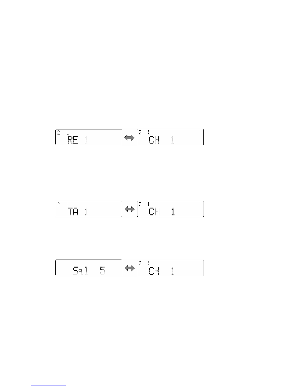
Press the key programmed as [Reverse] to toggle the reverse frequency function ON and
OFF.
ON OFF
Talkaround
If Talkaround is programmed, the transmit frequency can be changed to be the same as
the receive frequency. The CTCSS/DCS encoding signals also change to be the same as
the decoding signals.
Press the key programmed as [TA] to toggle the Talka round function ON and OFF.
ON OFF
Selectable Squelch Level
1. Press the key programmed as [SEL SQL], the current squelch level is displayed on the
LCD as shown below.
2. Turn the Selector Knob to select your desired squelch level.
3. Press any key other than the power switch to save the selected squelch level. The
LCD returns to the original display mode .
Note: If the squelch level is set too high, you may not efficiently receive weak signals; if
the level is set too low, you may hear a constant white noise, a sputtering noise, or
unwanted signals.
User Selectable Tone (CTCSS/DCS)
This function can be programmed by your dealer to temporarily change the preset
CTCSS/DCS frequency on a channel.
25
Page 26
1. Select your desired channel.
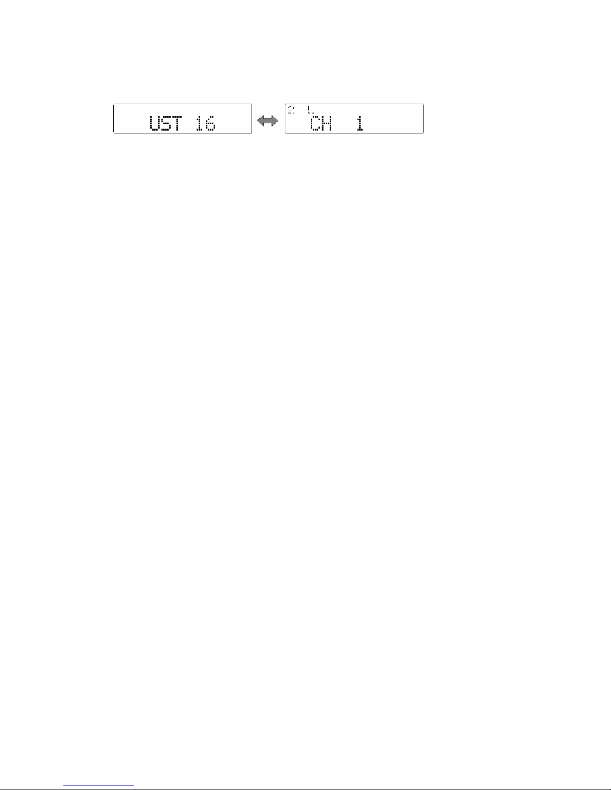
2. Press the key programmed as [UST] to enter the UST mode.
3. Use the Selector Knob to select a desired UST code/ name . The selected CTCSS/DCS
frequency is valid only in UST mode.
4. Press the [UST] key again, the radio exits from UST mode and the LCD returns to the
original display mode.
Public Address
This function can be used to amplify all the audio from the speaker and output the audio
through external speaker.
1. Press the key programmed as [PA] to activate Public Address function. “PA” appears
on the LCD display. Press the key again to deactivate this function and return to
normal user mode.
2. In PA mode, no transmission and reception occurs.
3. Hold down the [PTT] key and speak into the microphone, your voice can be heard
from the external speaker that is connected to the radio. “PA On” appears on the LCD
display.
4. Release the [PTT] key, the public address process halts and “PA” appears on the
LCD display.
Notes:
? In Public Address mode, turn the volume knob to adjust the volume.
? To use this function, the dealer should install public address optional accessory and
external speaker.
Dual Home Channels
Press the key programmed as [Home CH], the radio will go to the programmed home
channel.
When dual home channels are set, press the key programmed as [Home CH] to switch to
Home Channel 1, press again to switch to Home Channel 2, and press for the third time
to return to the original channel.
Horn Alert
1. Press the key programmed as [HA] to activate Horn Alert function, “HA” appears on the
LCD display.
2. The radio’s accessory ports HRI and HRO is connected when receiving calls of the
matching 2-Tone/5-Tone/DTMF/HDC2400TM code from the base station or other
radios.
3. Press the [HA] key again to exit from the Horn Alert mode.
Note:
This function is especially helpful when user is away from the radio. It can be used to
control the electronic devices over the air.
26
Page 27

Selectable Two-Tone Encode
1. Press the key programmed as [TTS], the programmed 2-Tone code or name will be
displayed on the LCD.
2. Turn the selector knob to select 2-Tone code (01-32) or name.
3. Hold down the [PTT] key to transmit the selected code.
4. Release the [PTT] key, signalling squelch turns off and radio LED flashes orange.
5. Press the key programmed as [MONI], signalling squelch turns back on.
Note: The radio will opens signalling squelch automatically if no signal is received for
the preset period of time.
Selectable Five-Tone Encode
1. Press the key programmed as [FTS], the programmed 5-Tone code or name will be
displayed on the LCD.
2. Turn the selector knob to select 5-Tone code (01-32) or name.
3. Hold down the [PTT] key to transmit the selected code.
4. Release the [PTT] key, signalling squelch turns off and radio LED flashes orange.
5. Press the key programmed as [MONI], signalling squelch turns back on.
Note: The radio will opens signalling squelch automatically if no signal is received for
the preset period of time.
Display Frequency
Press the key programmed as [DFreq], LCD will display the frequency of the current
channel.
Display Label
Press the key programmed as [DLabel], LCD will display channel label.
Display Mode
The radio will toggle among the 5 display modes each time when the key programmed as
[DMode] is pressed.
5 display modes are shown as follows:
Channel number
Channel label
Zone number
Zone label
Channel frequency
LCD Backlight
Press the key programmed as [LCD Backlight] to toggle LCD backlight on/off
Compander
Press the key programmed as [Compander] to toggle Compander on/off.
27
Page 28

Scrambler
Press the key programmed as [Scrambler] to toggle Scrambler on/off.
Note: Emphasis/de-emphasis features are turned off when scrambler is activated and
turned on when scrambler is deactivated.
GPS Report
When GPS receiver is installed, press the key programmed as [Send GPS] to transmit
your position data.
HDC2400
. HDC list
1. Press [HDC List ] key (programmable key) to view the preset HDC list item number or
name on the display.
2. Turn the selector knob to select the desired HDC list item number or name.
3. Press the PTT key to complete the call.
HDC can achieve the following functions: selective call (individual call, group call, zone
call, and broadcast), call alert and system function (stun, kill, revive, check) etc.
Short Message
Since Short Message function is realized through HDC2400TM, the channels of the
receiver and sender should be configured with optional signaling HDC2400TM.
Via multi level menu operation, short messages can be edited, saved, viewed, sent,
protected and deleted. Press [Message] key (programmable key) in user’s mode to enter
Short Message Menu.
“Receive Msg” Inbox can receive 38 messages at the most, with no more than 48
characters in each one.
“Message sent” Outbox can save 8 messages at the most, with no more than 48
characters in each one.
“Fixed Message” box can save 32 messages at the most, with no more than 31
characters in each one.
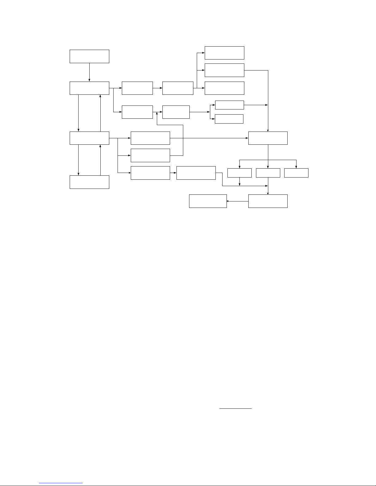
The main operation flow is illustrated as follows:
28
Page 29
0HVVDJH.H\
3URWHFW0RGH
7UDQVIHU0VJ
9LHZ0HVVDJH
6HQG0HVVDJH
'HOHWH$OO
5HFHLYH0VJ
0HVVDJH6HQW
1HZ0HVVDJH
0HVVDJH6HQW
)L[HG0HVVDJH
6HOHFW0VJ
6HOHFW0VJ
'HOHWH0VJ
7UDQVIHU0VJ
'HOHWH0VJ
0HVVDJH(GLW
6HOHFW0VJ
7UDQVPLW0VJ ,'6HOHFW
6HQG2QO\ 6DYH6HQG 6DYH2QO\
Menu Operation:
1) Press PF6 to confirm;
2) Press PF1 to return to the previous;
3) Turn the knob or press Up/Down key to select.
Message Receiving
The radio emits an alert tone and the icon is shown on the display when a message is
received (if corresponding functions are enabled). Press [Message] to view the message.
Message Sending and Deleting
Select “Send Message” in the main menu, followed with three options:
1) New message edition, “New Message” is shown on LCD;
2) Sent message, “Message sent” is shown on LCD;
3) Fixed message, “FixedMessage” is shown on LCD.
1. Sending new message:
1) Select the desired group and channel.
2) Press [Message] key (programmable key) to enter Short Message Menu and
select “Send Message”.
3) Select “New Message”.
4) Enter the message content (please refer to Appendix 1 for character input
methods).
5) Select “Send Only”, “Send&Save”, or “Save Only ” in the menu.
If “Send Only” or “ Send&Save” is selected, the following steps are required.
29
Page 30

6) Select sending type, “Individual” or “Group Call”.
7) Use the knob selection/keypad entering to determine the desired receiver ID
(individual/group). (Please refer to Appendix 1 for character input methods); or
press PF6 to enter ID menu.
8) Press PF6 or the PTT key to send message.
2. Sending or deleting sent message:
1) Select the desired group and channel.
2) Press [Message] key (programmable key) to enter Short Message Menu and
select “Send Message”.
3) Select “Message Sent”.
4) Select the desired message (Note 1)
5) Select “Transfer Msg” or “Delete Msg”.
If “Delete Msg” is selected, the selected massage will be deleted.
If “Transfer Msg” is selected, the following steps are required;
6) Select sending type, “Individual” or “Group Call”.
7) Use the knob selection/keypad entering to determine the desired receiver ID
(individual/group). (Please refer to Appendix 1 for character input methods); or
press PF6 to enter ID menu.
8) Press PF6 or the PTT key to send message.
3. Sending Fixed Message
1) Select the desired group and channel.
2) Press [Message] key (programmable key) to enter Short Message Menu and
select “Send Message”.
3) Select “FixedMessage”.
4) Select the desired fixed message (Note 1).
5) Select sending type, “Individual” or “Group Call”.
6) Use the knob selection/keypad entering to determine the desired receiver ID
(individual/group). (Please refer to Appendix 1 for character input methods); or
press PF6 to enter ID menu.
7) Press PF6 or the PTT key to send message.
Message Viewing and Deleting
Select “View Message” in the main menu, followed with two options:
1) To view received message, “Receive Msg” is shown on LCD;
2) To view sent message, “Message Sent” is shown on LCD;
1. Viewing or deleting received message
1) Select the desired group and channel;
2) Press [Message] key (programmable key) to enter Message Menu to choose
“View Message”;
3) Select “Receive Msg”;
4) Select the ID of the desired message;
30
Page 31

5) Select the content of the desired message;
6) Select “Protect Mode”, “Transfer Msg” or “Delete Msg”(Note 2);
If “Delete Msg” is selected, the selected massage will be deleted.
If “Transfer Msg” is selected, the following steps are required.
7) Select sending type, “Individual” or “Group Call”;
8) Use the knob selection/keypad entering to determine the desired receiver ID
(individual/group). (Please refer to Appendix 1 for character input methods); or
press PF6 to enter ID menu.
9) Press PF6 or the PTT key to send message.
2. Viewing or deleting sent message
1) Select the desired group and channel;
2) Press [Message] key (programmable key) to enter Short Message Menu and
choose “View Message”;
3) Select “Message Sent”;
4) Select the desired short message (Note 1);
5) Select “Transfer Msg” or “Delete Msg”.
If “Delete Msg” is selected, the selected massage will be deleted.
If “Transfer Msg” is selected, the following steps are the same as those 6)-8) in
“Sending Sent Message”. Please refer to “Sending Sent Message”.
Received Message Deleting
All the messages in the “Receive Msg” Inbox will be deleted after selecting “Delete
All” in the main menu and press PF6, except those are set with protect mode.
1) Press [Message] key (programmable key) to enter short message menu and choose
“Delete All”;
2) Delete all messages.
Note 1: If no message inside, “Empty” appears and the after operation cannot proceed.
Note 2: “A” icon appears if protect mode is selected. Press PF6 key to toggle between
protect and non-protect modes. The messages cannot be deleted in protect mode.
Optional Signalling (DTMF/2-Tone/5-Tone/HDC2400TM)
The preset functions are activated when the received signal matches the optional
signalling.
When optional signalling is programmed on a channel or zone, radio LED will flash
orange and the radio will sound an alert tone or transpond to the call if a signal containing
the correct tone/code is received.
? CTCSS/DCS AND / OR DTMF/2-Tone/5-Tone/HDC2400
Signalling
Logic
Squelch Alert Tone / Transpond
TM
31
Page 32
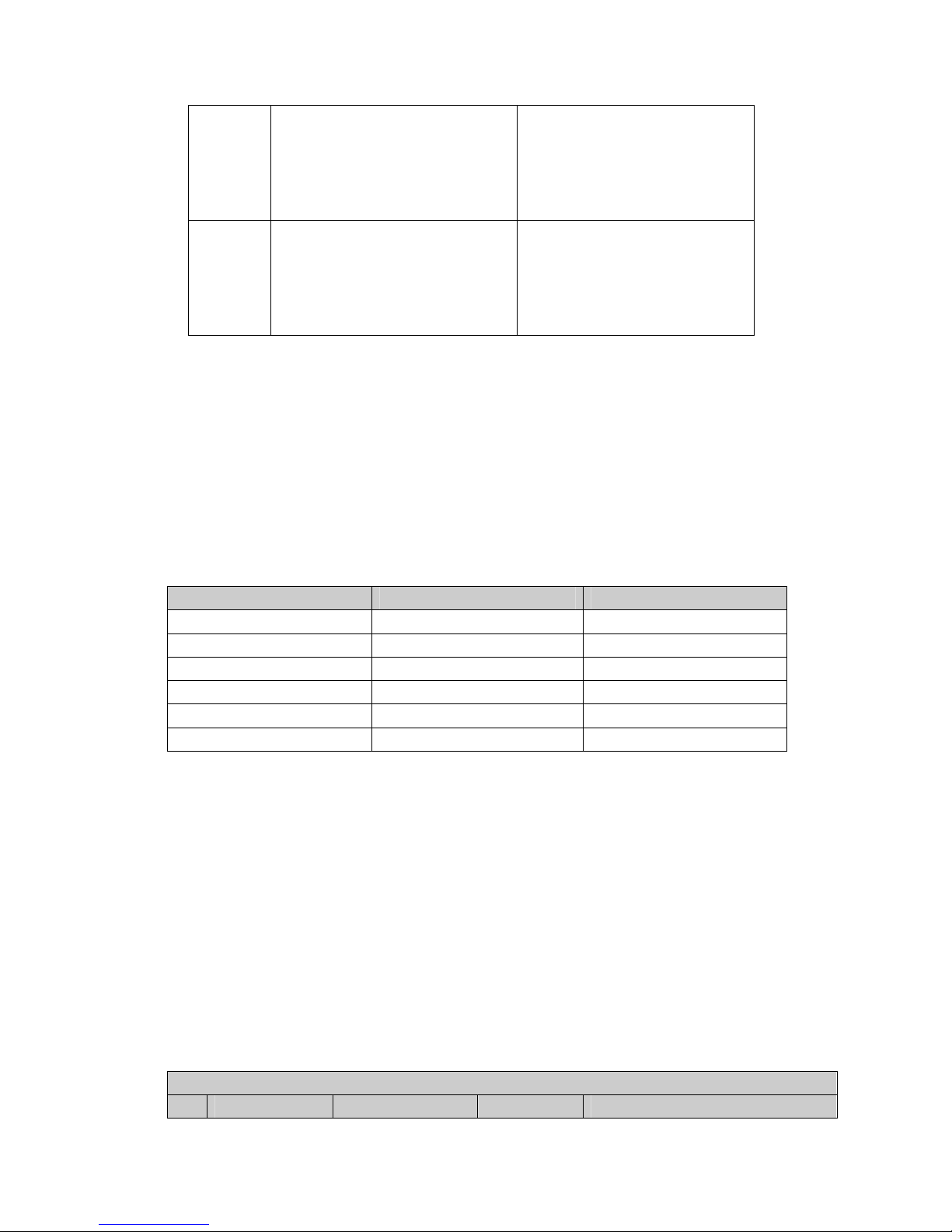
AND
OR
Unmutes only when both CTCSS/DCS
and Optional Signalling
(2-Tone/5-Tone/DTMF/HDC2400TM) are
received and matches the preset one
on selected channel.
Unmutes when either CTCSS/DCS or
Optional Signalling (2-Tone/5-Tone/
DTMF/HDC2400TM) is received and
matches the preset one on selected
channel.
Activated only when both
CTCSS/DCS and Optional Signalling
(2-Tone/5-Tone/DTMF/ HDC2400TM)
are received and matches the preset
one on selected channel.
Activated only when either
CTCSS/DCS or Optional Signalling
(2-Tone/5-Tone/DTMF/HDC2400TM) is
received and matches the preset one
on selected channel.
? Auto Reset
Signalling squelch will automatically turn back on when no signal is received for a preset
period of time.
User Set Mode
Turn the power on while holding down the [PF1] key, the radio enters User Set mode after
correct power-on password is entered (if Power-On Password is set). In User Set mode,
the following menus can be selected:
Main Menu
No. Menu Item LCD Display
1 Function Set Function Set
2 Power On Text Power On Text
3 Power On Password PWR Password
4 UST Code UST Code
5 Hook & Moni Hook & Moni
6 Key Assignment Key Assign
Press the [PF6] key to enter the selected menu. In User Set mode, turn the power off and
back on to enter the Conventional mode.
In User Set mode, you can operate as following:
1. Turn the Selector Knob to make settings;
2. Press the [PF6] key to save the settings and enter the next setting item;
3. Press [Up]/[Down] to select the setting item upwards/downwards without saving
the settings;
4. Press the [PF1] key to return to user set menu mode.
? Function Set
Select “Function Set” in main menu and press the [PF6] key to make settings as
following:
Function Set
No. Function Setting Display Remarks
32
Page 33
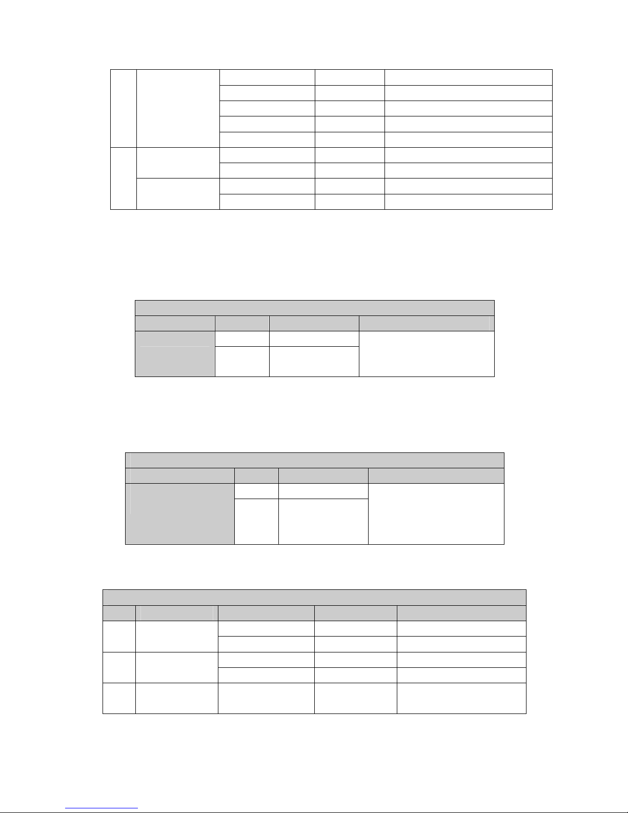
1
Home Channel
2
Home Channel 2
Home Off Home Off
Home 1 On Home 1 On
Home 2 On Home 2 On
Home Both On Home Both On
Zone Home Channel Home Zone
Zone 1 Selector Knob: change zone or channel Home Channel 1
Channel Home1 1 [PF5]: Toggle between zone and channel
Zone 1 Selector Knob: change zone or channel
Channel Home2 1 [PF5]: Toggle between zone and channel
? Power On Text
Select “Power on Text” in main menu and press the [PF6] key to make settings. The
power-on text will be displayed. Press the [PF1] key to enter Text Edit mode. Please refer
to Appendix 1 “Entering Characters” for more details.
Power On Text
Function Setting Display Remarks
Power On Text
Blank -------------------
Text Welcome
Please refer to Appendix 1
“Character Input”.
12 characters maximum.
? Power On Password
Select “PWR Password” in the main menu and press the [PF6] key to make settings.
“Power On Password” will be displayed. Press the [PF1] key to enter Password Edit
mode. Please refer to Appendix 1 “Entering Characters” for more details.
Power On Password
Function Setting Display Remarks
Power On Password
Blank ------------
Number 88888888
Please refer to Appendix 1
“Entering Characters”.
Numeric character only (8 digits
maximum).
? UST Code
Select “UST Code” in the main menu and press the [PF6] key to make settings.
UST Code
No. Function Setting Display Remarks
1-32 UST 1 1 UST Code No.
UST 32
ASCII CODE UST 1 2 UST Code Name
---------- No input
3
RX Signalling
Off R
PF5: OFF/CTCSS/CDCSS
Off
33
Page 34
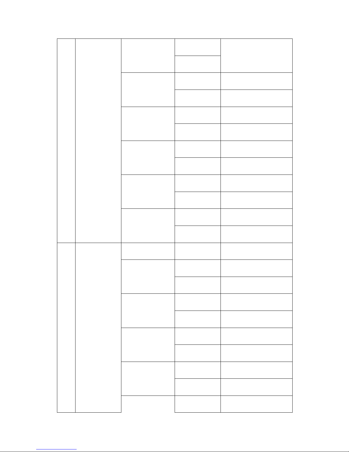
4
TX Signalling
CTCSS
(EIA standard mode) R CTCSS 67.0
67.0-254.1Hz R
CTCSS 254.1
CTCSS
(step: 0.1Hz)
R
CTCSS 67.0*
67.0-254.1Hz R
CTCSS 254.1*
CDCSS
(standard mode)
R
CDCSS 023N
023-754 R
CDCSS 754N
CDCSS
(1 step mode)
R
CDCSS 000N*
000-777 R
CDCSS 777N*
CDCSS
(standard mode)
R
CDCSS 023?
023-754 Reverse R
CDCSS 754?
CDCSS
(1 step mode)
R
CDCSS 000? *
000-777 Reverse R
CDCSS 777? *
OFF T
Off
CTCSS
(EIA standard mode) T CTCSS 67.0
67.0-254.1Hz R
CTCSS 254.1
CTCSS
(step: 0.1Hz)
T
CTCSS 67.0*
67.0-254.1Hz T
CTCSS 254.1*
CDCSS
(standard mode)
T
CDCSS 023N
023-754 T
CDCSS 754N
CDCSS
(1 step mode)
T
CDCSS 000N*
000-777 T
CDCSS 777N*
CDCSS
(standard mode)
T
CDCSS 023 I
[PF4]: Toggle between
standard mode and step mode
[PF3]: Toggle between CDCSS
and reverse CDCSS
[PF5]: OFF/CTCSS/CDCSS
[PF4]: Toggle between
standard mode and step mode
[PF3]: Toggle between CDCSS
and reverse CDCSS
34
Page 35
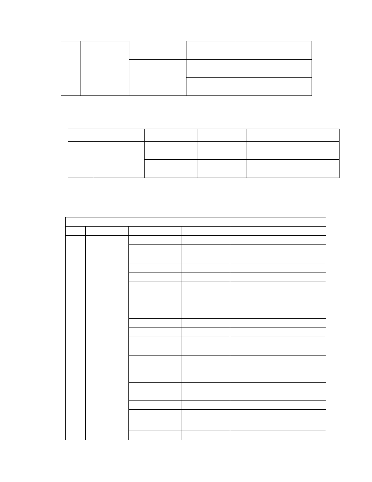
023-754 Reverse T
CDCSS
(1 step mode)
000-777 Reverse T
CDCSS 754 I
T
CDCSS 000 I*
CDCSS 777 I*
n Hook & Moni
Select submenu “Hook & Moni”, press [PF6] to enter Hook & Moni Mode.
NO. Function Setting Display Remarks
Hook HandMic Hook
1 Hook & Moni
Moni TableMicMoni
Selected when hand
microphone is used
Selected when desktop
microphone is used
? Key Assignment
Select “Key Assign” in the main menu and press the [PF6] key to program the
programmable keys PF1-PF6 as following:
Key Assignment
No. Function Key Setting Display Remarks
1 [PF1]
Off PF1 Off No function
VOL UP PF1 VOL UP Volume Up
VOL Down PF1 VOL Down Volume Down
CH Up PF1 CH Up Channel Up
CH Down PF1 CH Down Channel Down
Zone Up PF1 Zone Up Zone Up
Zone Down PF1 Zone Down Zone Down
MONI A PF1 MoniA Monitor A: Monitor Unmute -momentary
MONI B PF1 MoniB Monitor B: Monitor Unmute-Toggle
MONI C (default) PF1 MoniC Monitor C: Carrier Squelch-momentary
MONI D PF1 MoniD Monitor D: Carrier Squelch-Toggle
DisplayLabel PF1 DLabel Display channel label
Display Frequency PF1 Dfreq Display frequency
Display Mode PF1 Dmode Display toggles among channel
number, channel label and channel
frequency
User Selectable
Tone
Sel 2Tone PF1 Sel2Tone Select 2-Tone encode
Sel 5Tone PF1 Sel5Tone Select 5-Tone encode
PF1 UserTone Tone 01-32 (CTCSS/CDCSS)
Sel HDC
TX Power PF1 TXPower Switch transmit power
PFI SelHDC Select HDC encode
35
Page 36
Sel
HDC
PFI SelHDC
Scan PF1 Scan Scan
Add/Del PF1 Add/Del
Reverse PF1 Reverse Reverse frequency
Talk Around PF1 TA Talk around
SEL SQL PF1 SELSQL Select squelch level
Home CH PF1 HomeCH Home channel
Public Address PF1 PA Public address
Horn Alert PF1 HornAler Horn alert
LCD Backlight PF1 LCDBL LCD backlight
Scrambler PF1 Scramble Scrambler
Compander PF1 Compand Compander
AUX A PF1 AUX A AUX A Port output control
AUX B PF1 AUX B AUX B Port output control
Send GPS PF1 Send GPS Send GPS
Emergency Call PF1 Emergency Emergency call
Message PF1 Message Message
Select HDC encode PF2 Off No function
VOL UP PF2 VOL Up Increase volume
VOL Down PF2 VOL Down Decrease volume
CH Up PF2 CH Up Channel up
CH Down PF2 CH Down Channel down
Zone Up PF2 Zone Up Zone up
Zone Down PF2 Zone Down Zone down
MoniA PF2 MoniA Monitor A: Monitor Unmute-momentary
MoniB PF2 MoniB Monitor B: Monitor Unmute-Toggle
MoniC PF2 MoniC Monitor C: Carrier Squelch-momentary
MoniD PF2 MoniD Monitor D: Carrier Squelch-Toggle
DisplayLabel PF2 Dlabel Display channel label
Display Frequency PF2 DFreq Display frequency
DisplayMode
[default]
User Selectable
Tone
Sel 2Tone PF2 Sel2Tone Select 2-Tone encode
Sel 5Tone PF2 Sel5Tone Select 5-Tone encode
PF2 DMode Display toggles among channel
PF2 UserTone Tone 01-32 (CTCSS/CDCSS)
Add/Del as not at scan status
Temporarily delete nuisance channel
Temporarily delete priority channel
number, channel label and channel
frequency
Sel HDC
TX Power PF2 TXPower Switch transmit power
Scan PF2 Scan Scan
PF2 SelHDC Select HDC encode
Add/Del in non-scan mode
36
Page 37
Sel
HDC
PFI SelHDC
Temporarily delete nuisance channel Add/Del PF2 Add/Del
Temporarily delete priority channel
Reverse PF2 Reverse Reverse frequency
Talk Around PF2 TA Talk around
SEL SQL PF2 SELSQL Select squelch level
Home CH PF2 HomeCH Home channel
Public Address PF2 PA Public address
Horn Alert PF2 HornAler Horn alert
LCD Backlight PF2 LCDBL LCD backlight
Scrambler PF2 Scramble Scrambler
Compander PF2 Compand Compander
AUX A PF2 AUX A AUXA Port output control
AUX B PF2 AUX B AUXB Port output control
Send GPS PF2 Send GPS Send GPS
Emergency Call PF2 Emergency Emergency call
Message PF2 Message Message
Select HDC encode PF3 Off No function
VOL UP PF3 VOL Up Volume Up
VOL Down PF3 VOL Down Volume Down
CH Up PF3 CH Up Channel Up
CH Down PF3 CH Down Channel Down
Zone Up PF3 Zone Up Zone Up
Zone Down PF3 Zone Down Zone Down
MoniA PF3 MoniA Monitor A: Monitor Unmute-momentary
MoniB PF3 MoniB Monitor B: Monitor Unmute-Toggle
MoniC PF3 MoniC Monitor C: Carrier Squelch-momentary
MoniD PF3 MoniD Monitor D: Carrier Squelch-Toggle
DisplayLabel PF3 Dlabel Display channel label
Display Frequency PF3 DFreq Display frequency
Display Mode PF3 DMode Display toggles among channel
number, channel label and channel
frequency
User Selectable
Tone
Sel 2Tone PF3 Sel2Tone Select 2-Tone encode
Sel 5Tone PF3 Sel5Tone Select 5-Tone encode
PF3 UserTone Tone 01-32 (CTCSS/CDCSS)
Sel HDC
TX Power [default] PF3 TXPower Switch transmit power
Scan PF3 Scan Scan
Add/Del PF3 Add/Del
Reverse PF3 Reverse Reverse frequency
PF3 SelHDC Select HDC encode
Add/Del as not at scan status
Temporarily delete nuisance channel
Temporarily delete priority channel
37
Page 38
4 [PF4]
Talk Around PF3 TA Talk around
SEL SQL PF3 SELSQL Select squelch level
Home CH PF3 HomeCH Home channel
Public Address PF3 PA Public address
Horn Alert PF3 HornAler Horn alert
LCD Backlight PF3 LCDBL LCD backlight
Scrambler PF3 Scramble Scrambler
Compander PF3 Compand Compander
AUX A PF3 AUX A AUXA Port output control
AUX B PF3 AUX B AUXB Port output control
Send GPS PF3 Send GPS Send GPS
Emergency Call PF3 Emergency Emergency call
Message PF3 Message Message
Off PF4 Off No function
VOL UP PF4 VOL Up Volume Up
VOL Down PF4 VOL Down Volume Down
CH Up PF4 CH Up Channel Up
CH Down PF4 CH Down Channel Down
Zone Up PF4 Zone Up Zone Up
Zone Down PF4 Zone Down Zone Down
Moni A PF4 MoniA Monitor A: Monitor Unmute-momentary
Moni B PF4 MoniB Monitor B: Monitor Unmute-Toggle
Moni C PF4 MoniC Monitor C: Carrier Squelch-momentary
Moni D PF4 MoniD Monitor D: Carrier Squelch-Toggle
DisplayLabel PF4 Dlabel Display channel label
Display Frequency PF4 DFreq Display frequency
Display Mode PF4 DMode Display toggles among channel
number, channel label and channel
frequency
User Selectable
Tone
Sel 2Tone PF4 Sel2Tone Select 2-Tone encode
Sel 5Tone PF4 Sel5Tone Select 5-Tone encode
PF4 UserTone Tone 01-32 (CTCSS/CDCSS)
Sel HDC
TX Power PF4 TXPower Switch transmit power
Scan [default] PF4 Scan Scan
Add/Del PF4 Add/Del
Reverse PF4 Reverse Reverse frequency
Talk Around PF4 TA Talk around
SEL SQL PF4 SELSQL Select squelch level
Home CH PF4 HomeCH Home channel
PF4 SelHDC Select HDC encode
Add/Del as not at scan status
Temporarily delete nuisance channel
Temporarily delete priority channel
38
Page 39
5 [PF5]
Public Address PF4 PA Public address
Horn Alert PF4 HornAler Horn alert
LCD Backlight PF4 LCDBL LCD backlight
Scrambler PF4 Scramble Scrambler
Compander PF4 Compand Compander
AUX A PF4 AUX A AUXA Port output control
AUX B PF4 AUX B AUXB Port output control
Send GPS PF4 SendGPS Send GPS
Emergency Call PF4 Emergency Emergency call
Message PF4 Message Message
Off PF5 Off No function
VOL UP PF5 VOL Up Volume Up
VOL Down PF5 VOL Down Volume Down
CH Up PF5 CH Up Channel Up
CH Down PF5 CH Down Channel Down
Zone Up PF5 Zone Up Zone Up
Zone Down [default] PF5 Zone Down Zone Down
Moni A PF5 MoniA Monitor A: Monitor Unmute-momentary
Moni B PF5 MoniB Monitor B: Monitor Unmute-Toggle
Moni C PF5 MoniC Monitor C: Carrier Squelch-momentary
Moni D PF5 MoniD Monitor D: Carrier Squelch-Toggle
DisplayLabel PF5 Dlabel Display channel label
Display Frequency PF5 DFreq Display frequency
Display Mode PF5 DMode Display toggles among channel
number, channel label and channel
frequency
User Selectable
Tone
Sel 2Tone PF5 Sel2Tone Select 2-Tone encode
Sel 5Tone PF5 Sel5Tone Select 5-Tone encode
PF5 UserTone Tone 01-32 (CTCSS/CDCSS)
Sel HDC
TX Power PF5 TXPower Switch transmit power
Scan PF5 Scan Scan
Add/Del PF5 Add/Del
Reverse PF5 Reverse Reverse frequency
Talk Around PF5 TA Talk around
SEL SQL PF5 SELSQL Select squelch level
Home CH PF5 HomeCH Home channel
Public Address PF5 PA Public address
Horn Alert PF5 HornAler Horn alert
LCD Backlight PF5 LCDBL LCD backlight
PF5 SelHDC Select HDC encode
Add/Del as not at scan status
Temporarily delete nuisance channel
Temporarily delete priority channel
39
Page 40
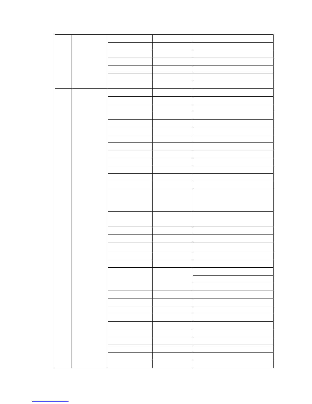
6
[PF6]
Scrambler PF5 Scramble Scrambler
Compander PF5 Compand Compander
AUX A PF5 AUX A AUXA Port output control
AUX B PF5 AUX B AUXB Port output control
Send GPS PF5 SendGPS Send GPS
Emergency Call PF5 Emergency Emergency call
Message PF5 Message Message
Off PF6 Off No function
VOL UP PF6 VOL Up Volume Up
VOL Down PF6 VOL Down Volume Down
CH Up PF6 CH Up Channel Up
CH Down PF6 CH Down Channel Down
Zone Up [default] PF6 Zone Up Zone Up
Zone Down PF6 Zone Down Zone Down
Moni A PF6 MoniA Monitor A: Monitor Unmute-momentary
Moni B PF6 MoniB Monitor B: Monitor Unmute-Toggle
Moni C PF6 MoniC Monitor C: Carrier Squelch-momentary
Moni D PF6 MoniD Monitor D: Carrier Squelch-Toggle
DisplayLabel PF6 Dlabel Display channel label
Display Frequency PF6 DFreq Display frequency
Display Mode PF6 DMode Display toggles among channel
number, channel label and channel
frequency
User Selectable
Tone
Sel 2Tone PF6 Sel2Tone Select 2-Tone encode
Sel 5Tone PF6 Sel5Tone Select 5-Tone encode
PF6 UserTone Tone 01-32 (CTCSS/CDCSS)
Sel HDC
TX Power PF6 TXPower Switch transmit power
Scan PF6 Scan Scan
Add/Del PF6 Add/Del
Reverse PF6 Reverse Reverse frequency
Talk Around PF6 TA Talk around
SEL SQL PF6 SELSQL Select squelch level
Home CH PF6 HomeCH Home channel
Public Address PF6 PA Public address
Horn Alert PF6 HornAler Horn alert
LCD Backlight PF6 LCDBL LCD backlight
Scrambler PF6 Scramble Scrambler
Compander PF6 Compand Compander
AUX A PF6 AUX A AUXA Port output control
PF6 SelHDC Select HDC encode
Add/Del as not at scan status
Temporarily delete nuisance channel
Temporarily delete priority channel
40
Page 41
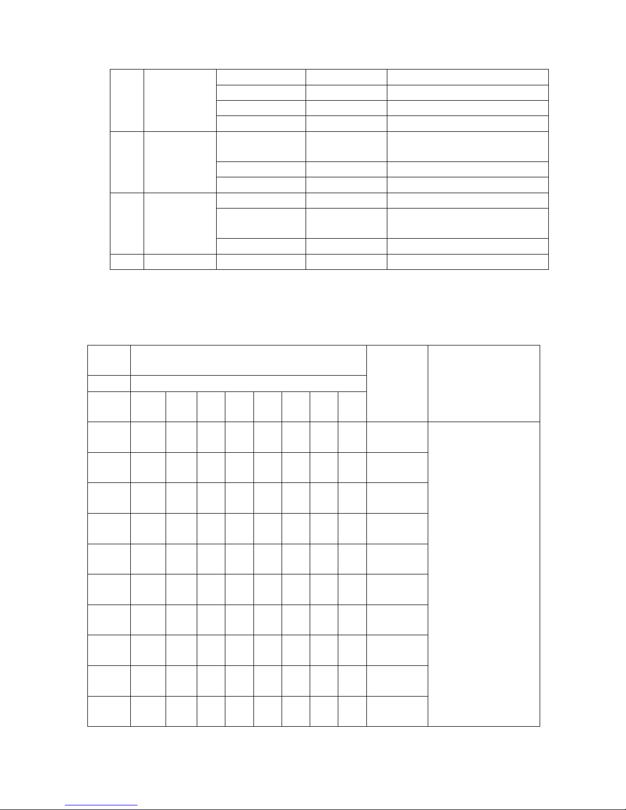
A
D
G
J
M
P
T
W
7 [Selector Knob]
8 [UP/Down]
9 END END END Indicate the end of menu options
AUX B PF6 AUX B AUXB Port output control
Send GPS PF6 SendGPS Send GPS
Emergency Call PF6 Emergency Emergency call
Message PF6 Message Message
Volume Knob
[Default]
Channel Knob Channel Knob Channel selector knob
Zone Knob Zone Knob Zone selector knob
Volume Up/Down Volume UpDn Volume Knob
Channel Up/Down
[Default]
Zone Up/Down Zone UpDn Zone selector knob
Volume Knob Volume Knob
Channel UpDn Channel selector knob
Appendix 1 Entering Characters
? Entering characters with an optional microphone keypad
KEY
Number of times key is pressed
CHARACTER
NUMBER
REMARKS
1 2 3 4 5 6 7 8
Space
1
2
3
4
5
6
7
8
9
1
B C a b c 2
E F d e f 3
H I g h i 4
K L j k l 5
N O m n o 6
Q R S p q r s 7
U V t u v 8
X Y Z w x y z 9
0 0
Each key can generate
numeric and character
information.
Pressing a key will cause
the first character of the
key’s character cycle to
appear on the LCD;
Subsequent pressing of
the same key will cause
subsequent characters in
the cycle to appear. For
example, to enter the
character “S”, press the
“7” key four (4) times.
41
Page 42
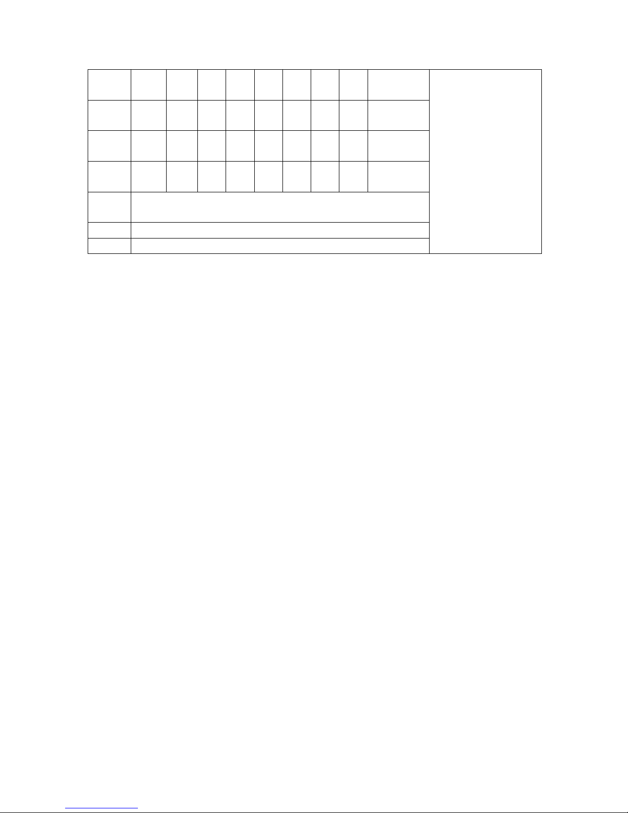
A @ ! # $ % ^ & ~
<
,
B + - * / = \ _ |
C ( )
D
Press to toggle between number and character
*
# Press to clear the input
PTT Enter (Complete programming and store)
. ? : ; “ ‘ `
> [ ] { }
? Entering characters without a keypad
? Turn Selector Knob to choose the character to be entered.
? Press the [PF2] key to toggle among number, uppercase letter, lowercase letter
and symbol.
? Press the [PF3] / [PF4] key to move the cursor forward/backward.
? Press the [PF1] key to clear the input.
? Press the [PF6] key to confirm the input.
42
Page 43

Optional Accessories
Keypad Microphone
Remote Mount Kit
Antenna
Cloning cable
Programming cable
External Speaker
RELM endeavors to achieve the accuracy and completeness of this manual, but cannot
guarantee its accuracy at all time. All the above specifications and design are subject to
change by RELM without notice.
All the reproduction and translation of this manual without authorization of RELM is not
allowed.
43
 Loading...