

Page 1
Page 2

TABLE OF CONTENTS
Introduction
.....................................................................................
1
Preparation For Use
........................................................................
2
Keyboard/Display Cover ...........................................................
2
Battery Installation ....................................................................
2
Antenna Installation ...................................................................
2
Radio Controls ................................................................................
3
Basic Operation ...............................................................................
4
Detailed Operation ..........................................................................
5
Display ......................................................................................
5
Keyboard
..................................................................................
5
Volume Control .........................................................................
5
Squelch Control
........................................................................
6
Channel Groups
.......................................................................
6
PTT Switch
...............................................................................
7
Code Guard Operation
.............................................................
8
Programming
...................................................................................
9
Programming
-
Keyboard Method ............................................
9
Cloning ......................................................................................
23
Programming From A Computer
..............................................
26
Accessories
.....................................................................................
27
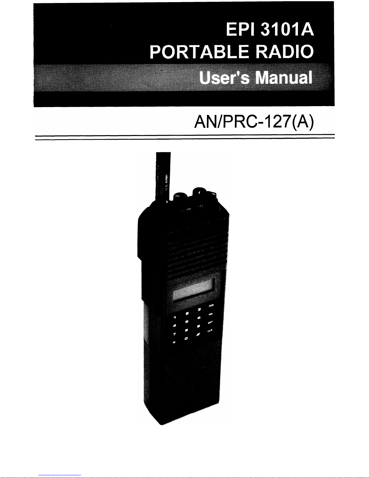
INTRODUCTION
This manual covers the operation and programming procedures for
RELM’s model EPI 3101AVHF Radio. The Radio provides two-way FM
communication on up to 28 channels, over a frequency range of 136
to 160 MHz, with an RF output of 3 watts.
This synthesized portable utilizes a microprocessor core allowing features
and performance designed to meet the requirements of a commercial
NDI NSUR as detailed in the Purchase Description, AN/PRC-127(A)
Radio Set. Using the information in this manual will help assure optimum
and proper performance from the Radio.
The Radio Set consists of the EPI 3101A Radio and the following
accessory items: LAAO126 Rechargeable Nickel-Cadmium Battery
(2),
LAA0312A Battery Charger, LAA0117 Battery Holder for 9 replaceable
AA batteries, LAA0818A Flexible Antenna, LAA0203A External Speaker/
Microphone and LAA0445A Carrying Case. All of these items, except for
the Radio, are shown on page 27.
EPI 3101A User’s Manual
1
Page 3
PREPARATION FOR USE
KEYBOARD/DISPLAY COVER
To remove or install the Keyboard/Display Cover, remove the battery if
installed. The Cover slides in grooves and latches at its bottom edge.
BATTERY INSTALLATION
A. Battery packs are available as a rechargeable type (LAA0126) or
as a non-rechargeable type (LAA01 17). Rechargeable battery packs
can be charged separately or while attached to a radio.
NOTE:
For safety reasons, rechargeable battery packs are shipped
uncharged or only partially charged. Therefore, a recharge-
able battery pack should be properly charged before use.
B.
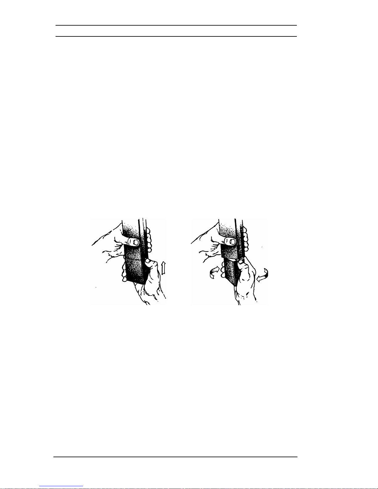
To install the battery pack, locate the center hub on the radio base
and place it in the recess of the battery pack. Position the pack at
the 30” offset, seating two metal studs in their recess. Apply upward
pressure to the pack while twisting the pack to its original position.
The metal tab will click, locking the pack in position.
C.
To remove the battery pack, first turn the radio off. Then, as shown
above, push up the metal tab on the side of the case while twisting
the battery pack approximately 30° and remove it from the radio.
NOTE:
All information programmed into the radio is maintained
even when the battery pack is removed.
D.
Periodically check the contacts on the battery pack for dirt that may
prevent a good electrical contact with the charging base.
WARNING:
Do not dispose of a battery pack in fire.
An explosion may occur.
ANTENNA INSTALLATION
Insert the flexible helical-wound antenna (LAA0818A) into the Unit’s
antenna connector and turn it clockwise until it is firmly seated.
2
Page 4
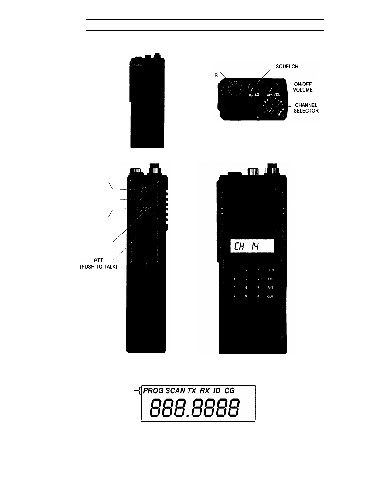
RADIO CONTROLS
FLEXIBLE
CODE GUARD
/
ANTENNA
CONNECT0
RADIO WITH
KEYBOARD/DISPLAY
COVERED
(REDUCED VIEW)
EXTERNAL
ANTENNA
JACK
\
ACCESSORY
-
JACK
MOUNT
f-
EARPHONE
/
JACK
/
(PUSH?TALK)
Annunciators -( PROG SCAN TX RX ID CG
/888.8888
7-SEGMENT LIQUID CRYSTAL DISPLAY
SPEAKER
MICROPHONE
LCD DISPLAY
KEYBOARD
EPI 3101A User’s Manual
3
Page 5
BASIC OPERATION
TRANSMIT
Ino
’
I
Ch
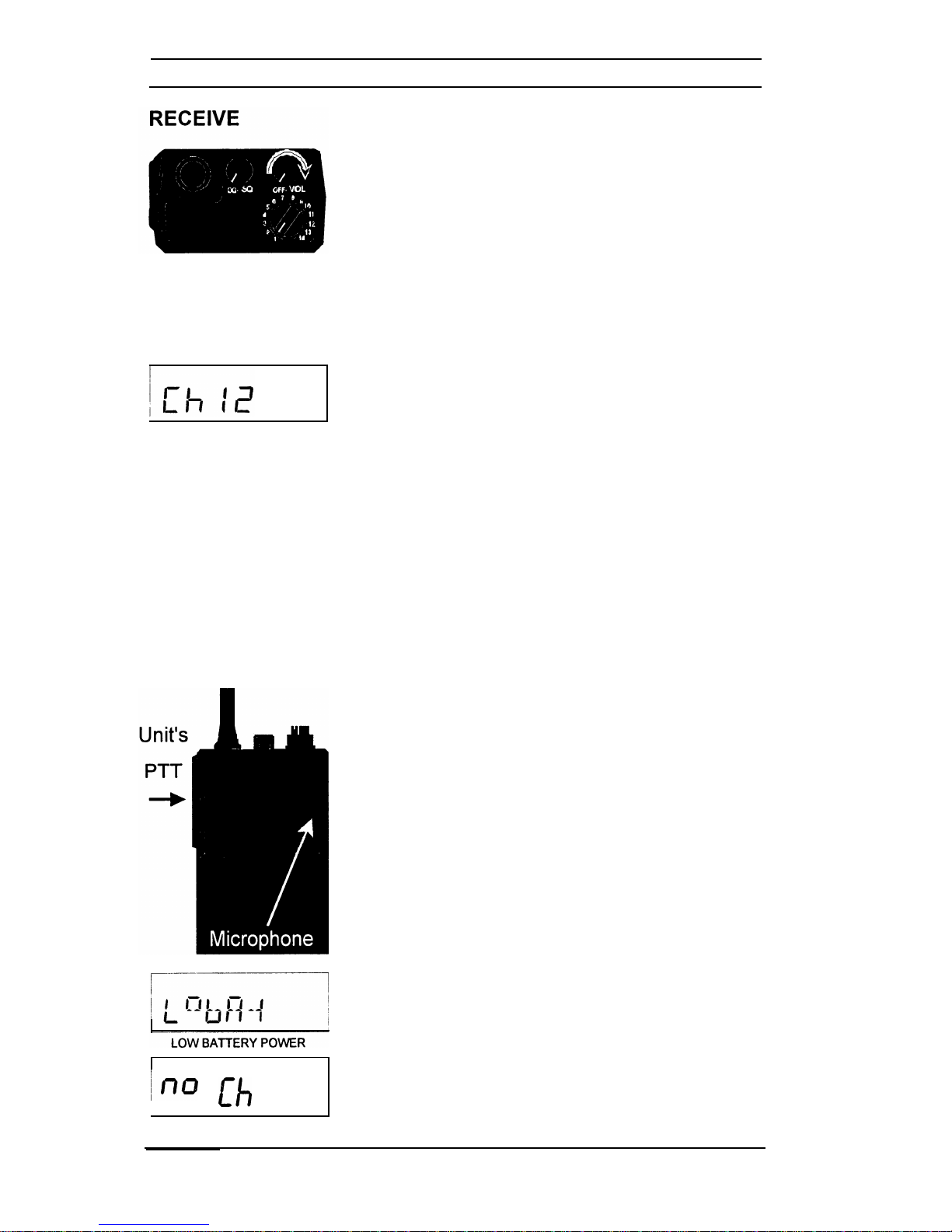
TURN POWER ON by turning the Volume knob
clockwise past the OFF detent. A beep sounds,
indicating the radio is operational. The LCD
briefly displays the current Group and then the
Channel.
S
ELECT A GROUP
by pressing the following keys
on the keyboard:
#,
2 (or
1)
and then ENT.
S
ELECT A CHANNEL
by turning the Channel Selector
knob.
ADJUST SQUELCH AND VOLUME by turning the
Squelch knob clockwise until a rushing noise is
heard. Set the volume to a comfortable level, then
turn the Squelch knob counterclockwise until the
noise stops. This is called the threshold squelch
setting.
Turning the Squelch knob fully counterclockwise
past the detent places the receiver in Code Guard
mode. A message will be heard only when the
proper Code Guard value is received.
Press the PTT (PushToTalk) switch. If installed,
use the Speaker/Microphone’s PTT. When the
transmitter is on, the LCD goes blank.
T
ALK IN A
NORMAL VOICE
With the microphone one
to two inches from your mouth.
R
ELEASE THE
PTT switch to stop transmitting.
If the LCD display does not go blank when you
press the PTT switch, the battery pack may need
to be charged; if so, the LCD will display LobAt.
If a warbling tone sounds and the display shows
no Ch, you are on a receive-only channel or the
channel is not programmed at all. Select an
authorized transmit channel.
If the length of your message exceeds the preset
timeout timersetting, the transmitter automatically
shuts off and a tone sounds. To continue the
transmission, release the PTT switch, then press
it again and continue talking.
4
Page 6
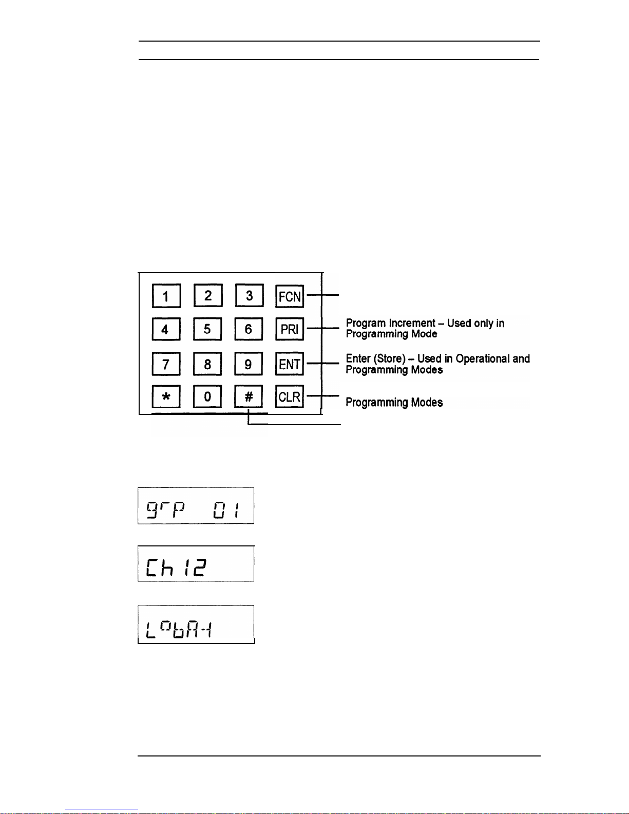
DETAILED OPERATION
DISPLAY
The Liquid Crystal Display (LCD) provides the User with visual information
pertaining to normal radio usage such as the channel number, group
number, transmit and battery status. In addition, confirmation of the
various programming steps and keyboard entries made while
programming are displayed.
KEYBOARD
The keyboard, as shown below, provides the User with operational and
programming functions as described later.
El El El E+-
Function - Used only in Programming
Mode
Clear (Erase) - Used in Operational and
J
Display Current Channel Group - Also
usec
in Programming Mode
VOLUME CONTROL
Rotating the Volume Control (OFF-VOL) Knob
clockwise from its detent (OFF) position turns the
Radio ON. The display will first show briefly the
current Channel Group. It will then show the
current Channel Number.
Rotating the Volume Control Knob fully counterclockwise to its detent position will turn the Unit
OFF. The display will briefly show
LobAt
and
then go blank. The
LobAt
indication is normal at
turn off.
EPI 3101A User’s Manual
5
Page 7
SQUELCH CONTROL
Rotate the Squelch Control (CG-SQ) Knob clockwise from its detent
(CG) position in order to hear any transmissions, regardless if they are
tone or digital coded or not. This, in effect,. is the Radio’s MONITOR
position. Turning the Squelch Control further clockwise until “noise” is
heard permits the Volume Control to be adjusted to a desired level, even
though an actual signal is not present.
CHANNEL GROUPS
678@
5
10
4
d
11
3
12
2
13
1
14
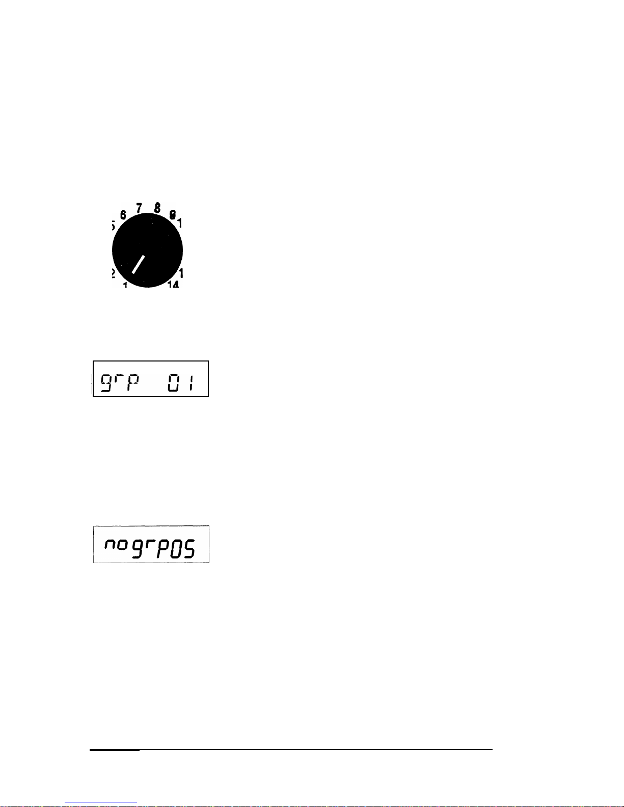
SELECT A GROUP
I I
GROUP NUMBER
‘nogrp05i
The Channel Selector knob has 14 positions. The
Radio has 28 channels which are separated into
two “groups” of 14 channels each. Group 01 is
factory programmed for narrow channel (12.5
kHz) FM reception. Channel Group 02 is
programmed for wide channel (25 kHz) FM
reception. Use Group 02 for proper communication
with the original AN/PRC-127 Radio.
P
RESS THE
#
KEY
on the keyboard to display the
current Channel Group number. If it isn’t the
desired Group, proceed to the next step.
P
RESS A NUMBER KEY
for the new Group number.
P
RESS THE
ENT
KEY
or wait about 5 seconds; the
radio returns to normal operation for the new
group, and the channel corresponding to the
Channel Selector’s position is displayed in the
LCD.
If an invalid number is selected (05 for example)
when selecting a Channel Group, the LCD displays
nogrp05
(no Group 05) immediately if
ENT
is
pressed, or in about 5 seconds if not pressed.
Then, after 5 seconds, the radio returns to the
previously selected group.
6
Page 8
Rotate the Channel Selector knob to the desired channel. Please note
that not all 14 channels may be programmed. Therefore, select only an
authorized (programmed) channel for communication purposes.
PTT SWITCH
7x
Ch :z
I
I
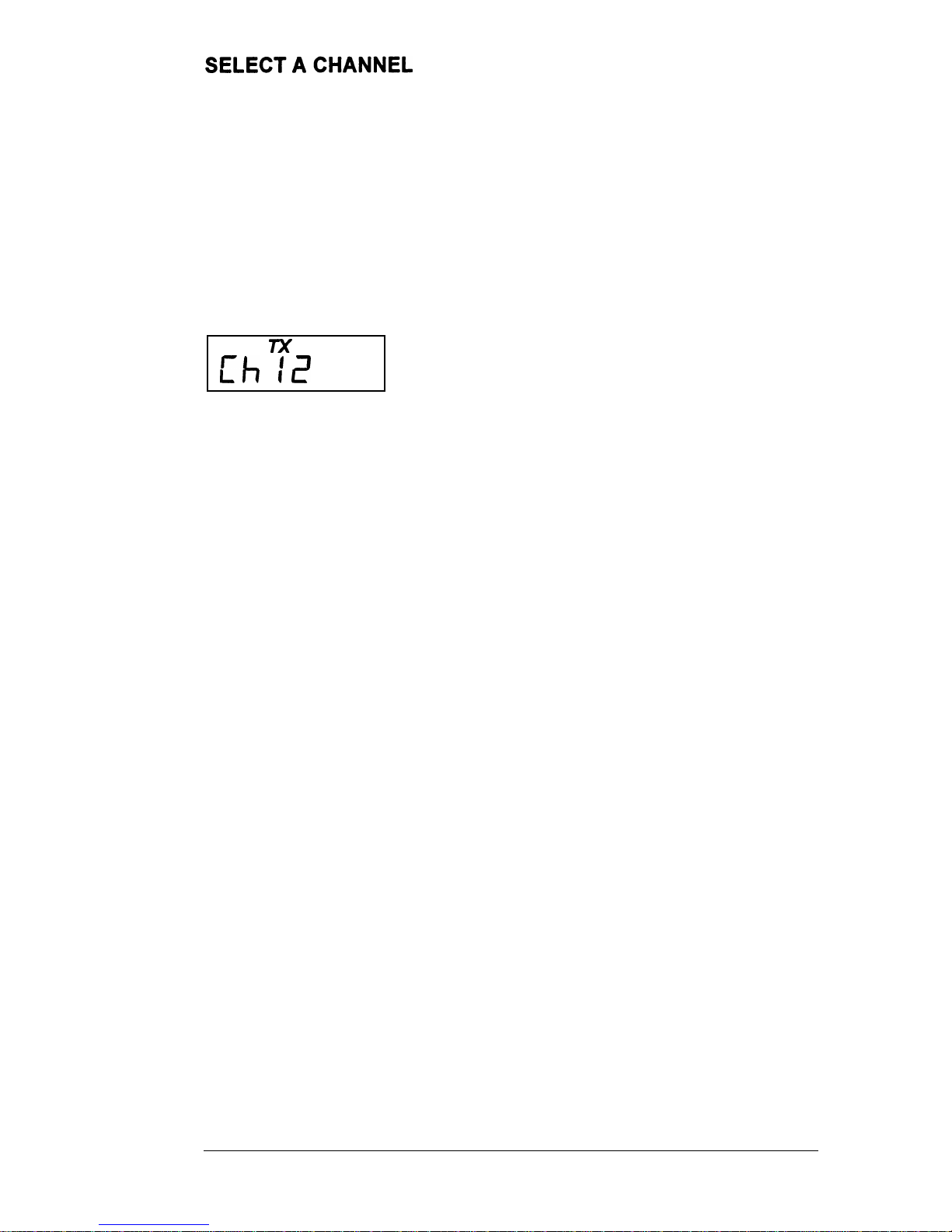
The PTT (Push-To-Talk) Switch activates the
Radio’s transmitter section when pressed and
held in. The display goes blank, indicating the
transmitter is activated.
When
the
PTT
switch is released, the transmitter
is deactivated and the display shows the current
Channel Number and, very briefly, the small TX
annunciator.
If the length of the message or transmission
(PTT
held in) exceeds the Radio’s programmed
Transmit Timeout
value, the transmitter will
automatically shut off and an error tone will be
heard. In addition, the display will show the current
Channel Number and the small TX annunciator.
To continue with the transmission, momentarily
release the PTT switch, press it
again
and then
resume talking.
REMINDER:
If you forgetwhat thecurrent Channel
Group is, press # and the display will show the
Group’s number. Press the
ENT
key or wait about
5 seconds and the display will return to showing
the current channel.
EPI 3101A User’s Manual
7
Page 9
CODE GUARD OPERATION
Code GuardTM, Tone or Digital, allows one radio or group of radios to be
selectively called within a system. If the radio has been programmed
with Code Guard, use the following receive and transmit instructions.
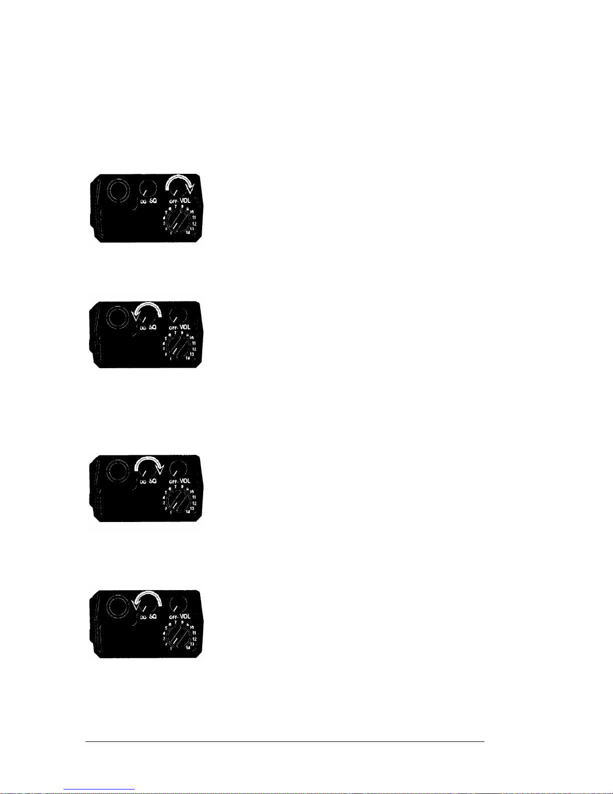
CODE GUARD RECEIVE
TURN POWER ON by turning the Volume knob
clockwise past the OFF detent.
SELECT A CODE GUARD CHANNEL by turning the
Channel Selector knob.
ADJUST VOLUME by turning the Squelch knob
clockwise until a rushing noise is heard, then
turning the Volume knob to a comfortable level.
SET CODE GUARD MODE by turning the Squelch
knob completely counterclockwise, past the detent
to the CG position. A message will be heard only
when the proper Code Guard value is received.
CODE GUARD TRANSMIT
T
URN THE
S
QUELCH
KNOB
clockwise, off the detent.
MONITOR THE CODE GUARD CHANNEL before
transmitting.
PRESS THE PTT (Push-To-Talk) switch if the
channel is not busy (signal is not present). When
the transmitter is activated, the LCD goes blank.
RESET THE SQUELCH KNOB to the Code Guard
position (CG) to receive only the messages with
the proper Code Guard value. During extended
transmissions the squelch can be left open (off
the detent) until the exchange has ended.
Code Guard is a trademark of BK Radio, Inc.
8
Page 10
PROGRAMMING
There are three different ways to program an EPI 3101A radio:
A. It can be programmed and/or reviewed using its internal keyboard.
This section of the manual describes that procedure.
B.
Another radio (MASTER) with the desired information can transfer
its programmed settings to the radio (SLAVE) by using a cloning
cable, LAA0700. See “Cloning” on page 23.
C.
It can be programmed from a computer by using a special RS-232
interface cable. That procedure is not described in this manual.
See page 26 for more details.
PROGRAMMING - KEYBOARD METHOD
Radios are shipped with a removable door covering the keyboard and
display. Before programming or reviewing, remove the door. First,
remove the battery pack if installed. Then, engaging the door just below
the speaker grill, slide the door downward. Reinstall the battery pack.
Make sure the battery pack is charged.
1.
Turn the radio on.
2.
Select the Channel Group to be
programmed or reviewed.
3.
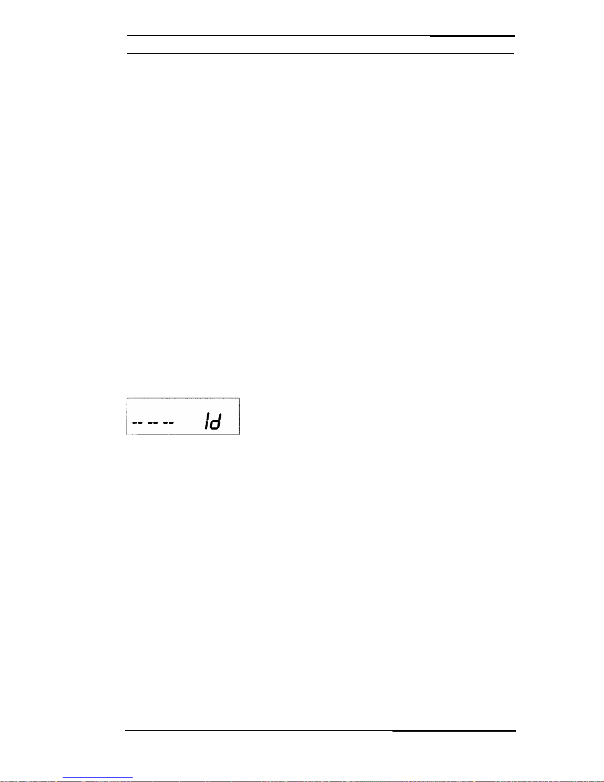
Press and hold the
FCN
key. After
approximately three seconds, the LCD will
display
- - -
Id.
4.
Release the
FCN
key. The radio is now in
the password entry mode.
5.
Enter the six-digit Password Code.
IMPORTANT:
VVithout
the correct Password
Code, you cannot proceed with reviewing
or programming. The same Password
Code is used for both Channel Groups.
New radios shipped from the factory are
assigned the Password Code 000000.
While entering the Password Code, the
display will not change, but a beep will
sound for each key pressed. If the
Password Code is entered incorrectly, the
radio will reset to normal operation. Try
again, starting at step 3.
EPI 3101A User’s Manual
9
Page 11
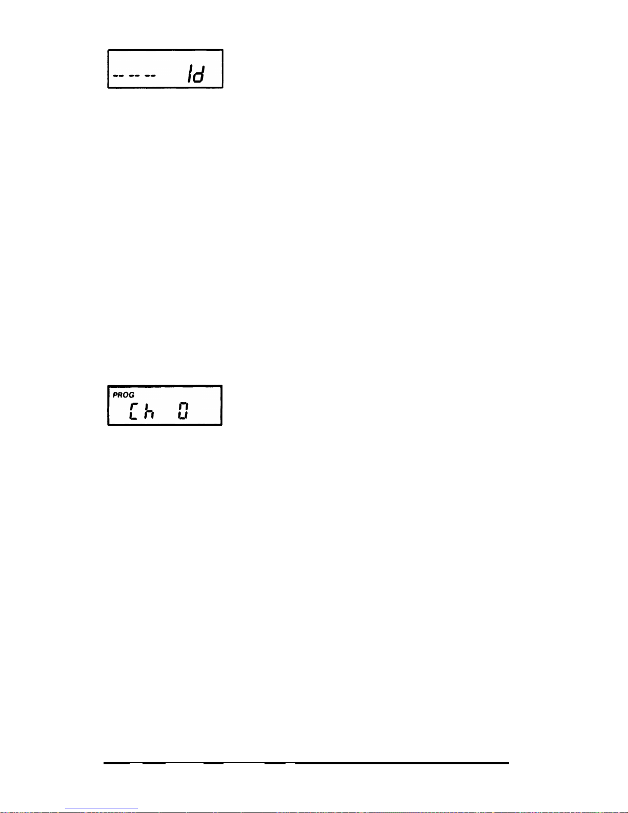
6.
To keep the Password Code unchanged,
I------
radio programming
press the
ENT
key and continue with normal
.
To change the Password Code, press the
FCN
key and enter a new six-digit password
code. The’digits are now displayed as you
enter them. The Password Code can
contain the digits 0 through 9, *, and #. The
*
is represented as a b and the # is
represented as an A in the display.
IMPORTANT:
Do NOT use a 1 for the first digit
of the Password Code
-
the radio will
malfunction. It will then require using a
computer program to correct the Password
Code and put the radio back into normal
operating condition.
If you make an errorwhile entering the new
Password Code, press the
CLR
key and
try again.
I”ehl
7.
Press the
ENT
key to store the new
Password Code and proceed to the
programming mode. The display will
change to
PROG Ch 0.
The Radio is now
ready for Reviewing and/or Programming.
TO REVIEW GENERAL RADIO PERFORMANCE VARIABLES
(CHANNEL 0):
Channel 0 is the portion of the program that controls the general
performance variables for each Group of 14 channels in a 28-channel
radio. Thus, the Channel 0 settings for each Channel Group must be
reviewed or programmed separately.
NOTE:
Settings listed as Group One Functions and Group Two
Functions refer to reviewing or programming Function Groups,
not the two Channel Groups 01 and 02.
10
Page 12

Channel 0 Settings for each Channel Group include:
Factory Program
Description Setting Display
ID or Automatic Number Identification (ANI)’
1234567 1234567
Transmit Timeout Timer
disabled
0 sec.
Scan Delay Time
disabled 0.0 sec.
Group One Functions 1-12345
Battery Saver lnhibit 1-1 (See Note 3)
disabled
1-12345
Priority Scan Operation 1-2 & 3
disabled
1-12345
\I/
Priority Key Lockout
1-4
enabled
1-12345
/I\
\I/
Scan List Lockout 1-5
enabled
1-1 234,5,
Group Two Functions 2-12345
User Code Guard Selection 2-1 disabled
2-12345
Busy Channel Operation 2-2 & 3
disabled
2-12345
ID or ANI Enable 2-4
disabled
2-12345
DTMF Enable 2-5 disabled
2-12345
NOTES:
1.
The ID Number is initially used for production purposes and the
2
.
Number shown is only an example.
Only the ID, Transmit Timeout Timer and Battery Saver Inhibit
may be changed from the Factory settings. Scan Delay Time
and all other Functions should not be changed.
3
.
It is highly recommended that the ID, Transmit Timeout Timer
and Battery Saver Inhibit settings be the same for Channel
Group 01 and Channel Group 02.
Battery Saver Inhibit should be enabled only in order to get
proper voltage readings when the Unit is being serviced, or if the
system in which the Unit is being used requires an extremely fast
squelch attack time. However, the Radio’s current drain and
battery life specifications are based upon the Battery Saver
being turned on.
\I/
4.
;1,
for example, indicates that Function (l-1) is enabled and its
corresponding number(s) in the display is flashing.
When
a
Function is disabled, its corresponding number(s) is steady.
EPI 3101A User’s Manual
11
Page 13
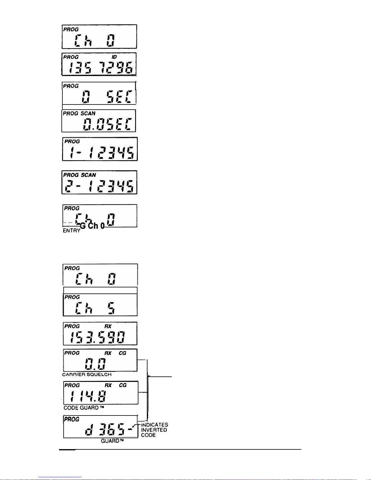
1.
After entering the Program Mode, the
display will show
PROG Ch 0.
2.
Press the
FCN
key. The display will show
]:pshj
length).
an ID number (up to seven digits in
IPROG
TX 1
3.
Press the
FCN
key. The display will show
the Transmit Timeout Timer length in
seconds.
4.
Press the
FCN
key. The display will show
the Scan Delay Time in seconds.
5.
Press the
FCN
key. The display will show
the five individual Functions of Group One
that are enabled or disabled.
6.
Press the
FCN
key. The display will show
the five individual Functions of Group Two
that are enabled or disabled.
11
7.
Press the
FCN
key. The display will loop
back to the Channel 0 entry point and show
PROGChO
ENTRY POINT
.
TO REVIEW FREQUENCIES AND CODE GUARD FOR AN
INDIVIDUAL CHANNEL IN THE SELECTED CHANNEL GROUP:
I
PROG RX CG
I-
1
1.
After entering the program mode,
the display will show
PROG Ch 0.
2.
Press
CLR
and then press the digit
key(s) of the channel that needs to
be reviewed. The display will show
the channel to be reviewed.
3.
Press the
FCN
key. The display will
show the receive frequency in MHz.
4.
Press the
FCN
key. The display will
show the receive Tone Code Guard
or Digital Code Guard (the value 0.0
denotes carrier squelch). Digital
Code Guard will be a three digit
number preceded by a
d
in the
display.
DIGITAL CODE GUAROTY
12
Page 14
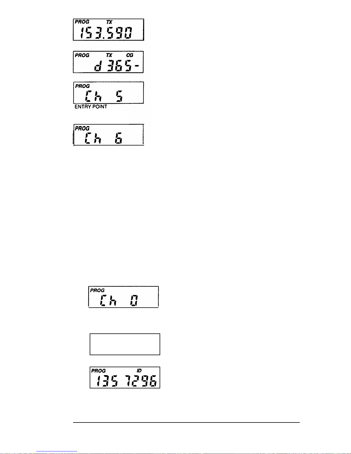
5.
Press the FCN key. The display will
show the transmit frequency in MHz.
6.
Press the FCN key. The display will
show the transmit Tone Code Guard
or Digital Code Guard. (Inverted
Digital Code Guard illustrated.)
7.
Press the FCN key. The display will
loop back to the entry point and
display the reviewed channel.
I PROG
8.
Press PRI to increment the channel
number by 1, or press CLR and then
press the digit key(s) of the next
channel to be reviewed. The FCN
key can then be used to review the
frequencies and Code Guard of this
next channel.
9.
To leave the programming mode,
power the unit down by rotating the
volume knob counter clockwise to
the OFF position. Normal operation
will occur on the next power up.
TO PROGRAM GENERAL RADIO PERFORMANCE VARIABLES
(CH 0) OF THE SELECTED CHANNEL GROUP:
A. To Set the ID Number
PROG
ID
1.
After selecting the desired Channel
Group (01 or 02) and entering the
program mode (see page
9),
the
display will show PROG Ch 0.
2.
Press the FCN key.
3.
The display will be blank or will show
a one to a seven digit ID number.
This ID number is intended as an
electronic serial number for radio
system management purposes.
EPI 3101A User’s Manual
13
Page 15
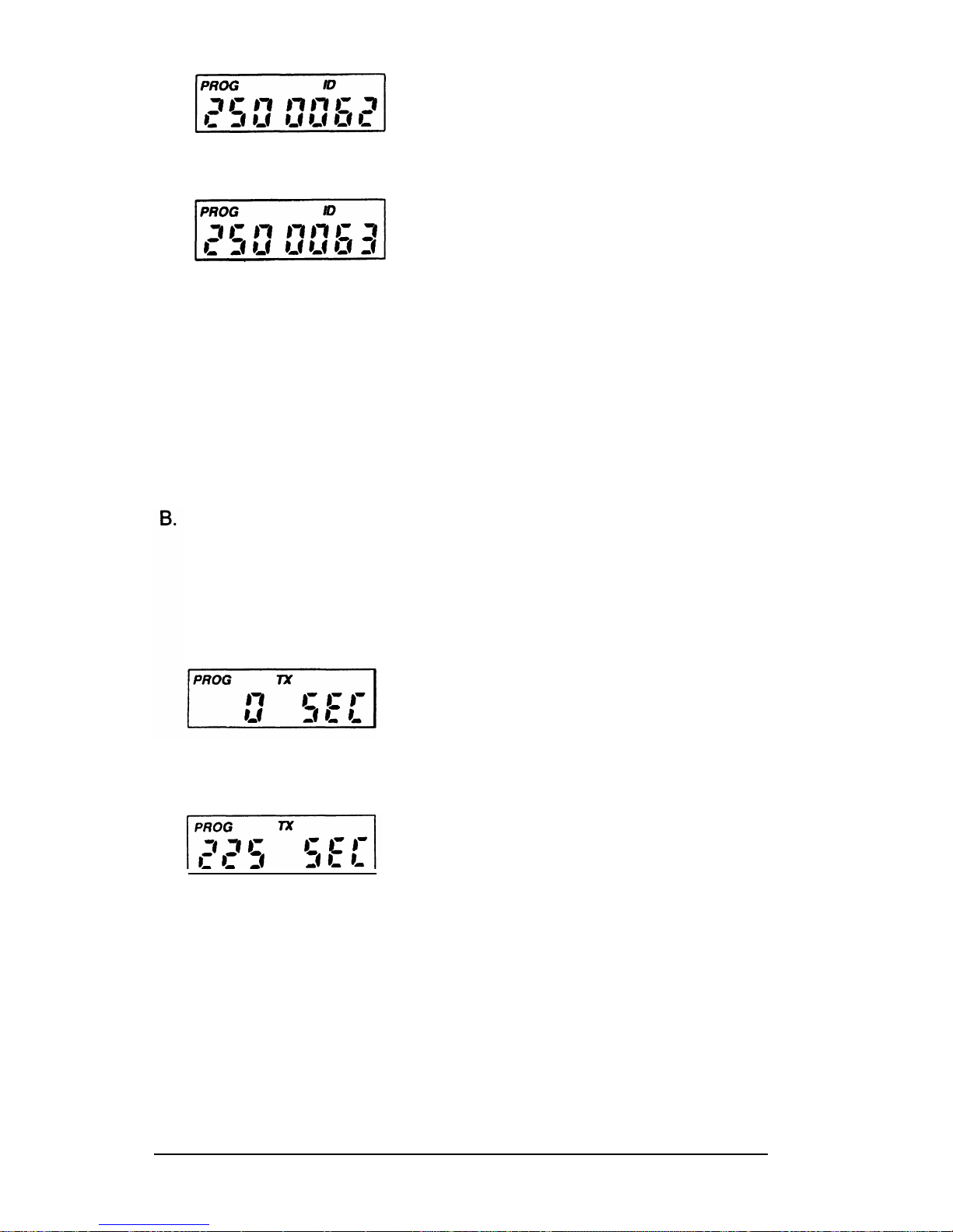
4a. If no change is needed for the ID
number, press FCN to advance to
the next section.
4b. If necessary, a new number can be
entered by pressing
CLR,
followed
by any number consisting of one to
seven digits. The digits will appear
at the right of the screen and move
to the left as more digits are entered.
Press
ENT
to store the new ID
number and automatically advance
to the next section.
4c. If desired, the existing ID number
can be incremented by 1 by pressing
PRI.
Then press
ENT
to store the
new ID number and automatically
advance to the next section.
To Set the Transmit Timeout Timer
After the ID number is set, the upper display will show
PROG TX.
This is the duration of the Transmit Timeout Timer. 0
SEC
means
that the Timeout Timer is disabled and the Unit will transmit as long
as the PTT switch is held in.
1.
If no change is needed, press
FCN
to advance to the next section.
2.
The Timeout Timer length can be
changed by pressing the
PRI
or
CLR
key. Each press of the
PRI
key will
increment or increase the length by
15 seconds, up to 225 seconds (3
minutes, 45 seconds).
Another pressafter 225 seconds
resets the value to 0. Pressing the
CLR
key will automatically reset the
value to 0. Press
ENT
to store the
chosen value and automatically
advance to the next section.
14
Page 16
E
.
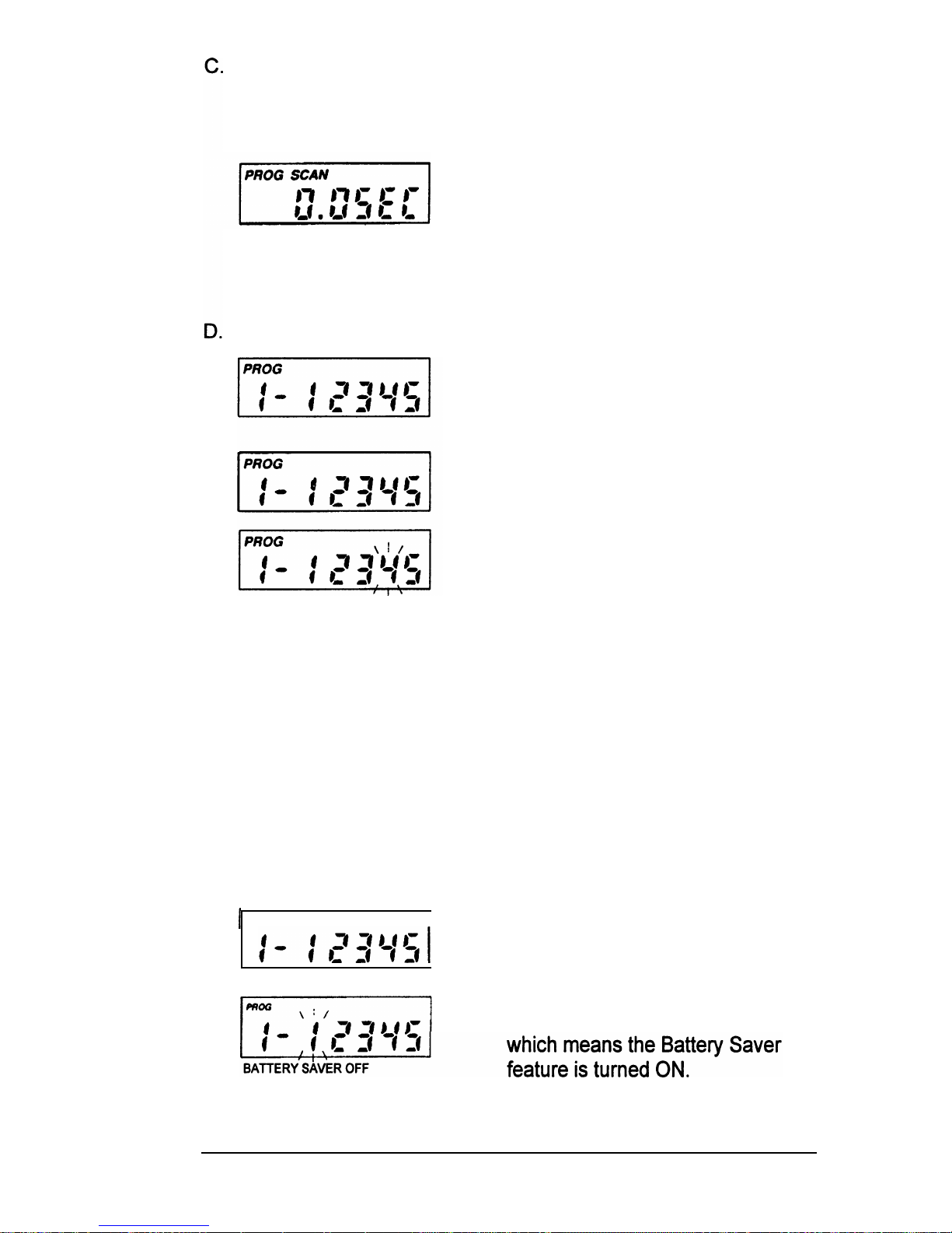
To Set the Scan Delay Time
After the Timeout Timer is set, the upper display will show
PROG
SCAN.
This is the duration of the Scan Delay Time in seconds.
Since the radio does not have a Scan
feature, no change is needed. Press
FCN
to advance to the next section.
NOTE:
It is highly recommended to leave
the Scan Delay Time at 0 seconds.
Miscellaneous Channel 0 Programming -GROUP ONE FUNCTIONS
After the Scan Delay Time is shown, the
display will show
PROG I- 12345.
This
is a group of five individual functions that
can be enabled or disabled.
NOTE:
See page 11 for Description and
Factory Settings information.
When a Function is enabled, the
corresponding number in the display will
flash. When the Function is disabled the
number is steady. If you wish to change
the Function from enable to disable, or
vice versa, press the number key
corresponding to that Function.
Once each Function 1-5 is set as desired,
press
ENT
to store them into memory
and automatically advance the program
to the next section.
If no changes have been entered, press
FCN
to advance to the next section.
GROUP ONE Functions
1
PROG
I
1.
Battery Saver Inhibit - If needed,
press the
1
key to change the Battery
Saver’s status.
BATTERY SAVER ON
REMINDER:
If 1 is steady, the
Battery Saver Inhibit is disabled,
EPI 3101A User’s Manual
15
Page 17
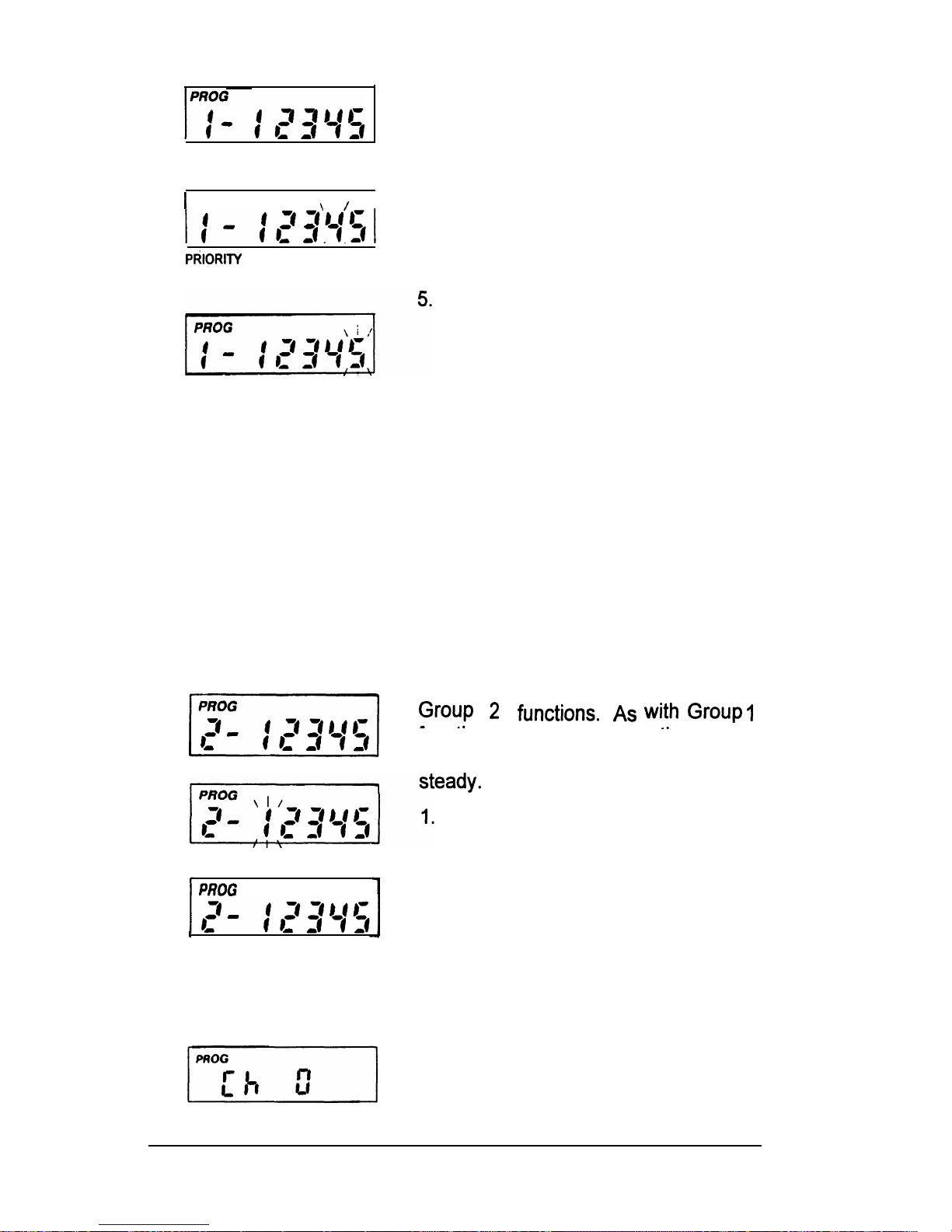
2 & 3.
4
.
1 PROG
\
I /
I
PdlORlTV CHANNEL NOT CHANGEABLE
SCAN LIST NOT CHANGEABLE
Functions 2 and 3 are used to define
Priority Scan operation. Since
Priority Scan is not available, both 2
and 3 should be steady.
PRI
Key Lockout-When enabled
(flashing) the
PRI
key will be locked
out in the operating mode. Because
the PRIORITY feature is not
available, the 4 should be flashing.
Scan List Lockout -
VVhen
enabled
(flashing), the User will not be able
to change the channels in the scan
list. Since SCAN is not available,
the 5 should be flashing.
Once each function l-5 is set as
desired, press
ENT
to store them
into memory and automatically
advance the program to the next
section.
If no changes have been entered,
press
FCN
to advance to the next
section.
F.
Miscellaneous Channel 0 Programming-GROUPTWO FUNCTIONS
After Group 1 functions are set, the
v/
display will show PROG 2-12345 for
Gyp
2
functims.
As
with
Group
1
functions, the enabled function number
will flash. The disabled functions remain
USER CODE GUARD ENABLED
User Code Guard Selection - When
disabled (steady), the keyboard can
not be used for Code Guard
Selection while in the Operating
mode. The
1
should not be flashing.
PROG
,
I
USER CODE GUARD DISABLED
NOTE:
Functions 2 through 5 are
reserved for future options and
should remain disabled (steady) at
this time.
Once Group Two functions are set,
press
ENT
to store the functions into
memory. The display will revert back
to the
Ch 0
entry point.
16
Page 18
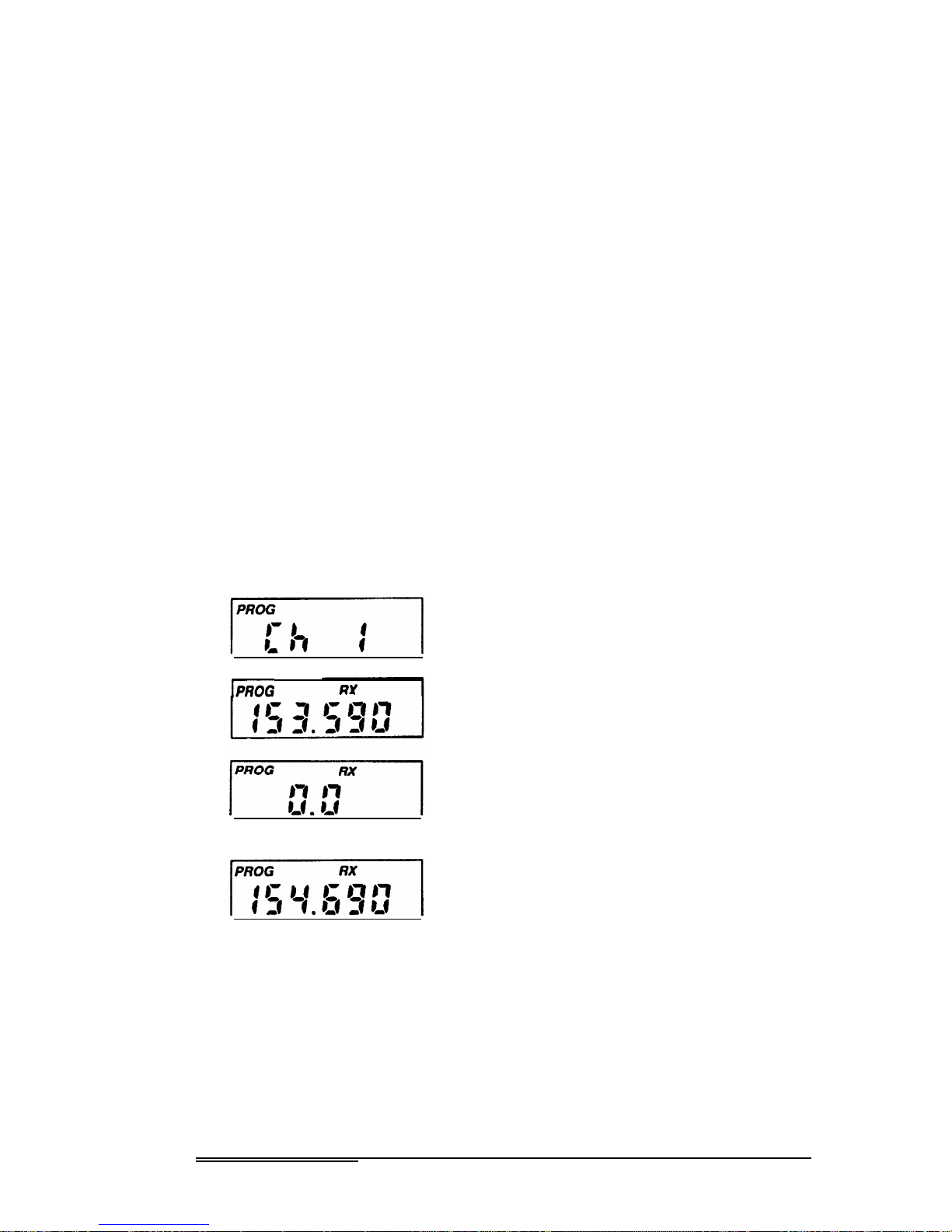
G. To Review Channel 0 Values
Repeated pressing of the
FCN
key will display each value in Channel
0, then loop back to the
Ch
0 entry point. To program the Channels
1 through 14, continue with the next Section. To quit programming,
go to page 20 for details.
TO PROGRAM CHANNEL FREQUENCIES AND CODE GUARD
VALUES:
Once Channel 0 programming is complete, the display will show
PROG Ch
0. Any channel number 1 through
14
can now be pressed
to allow access to the frequency and Code Guard values for that
channel in its Group (01 or 02).
IMPORTANT:
To improve the interoperability clarity between the
AN/PRC-127(A) and the AN/PRC-127 Radio Set, two separate
channel Groups are designated in the AN/PRC-127(A) Radio
Set and must be programmed to receive the same frequency in
both Groups (01 and 02).
Example:
VVhen
programming a 127A, a channel in Group 02
can be programmed to receive on 160.000 MHz with a “127
characteristic” receive mode. At this time, the same channel in
Group 01 can be programmed to receive on 160.000 MHz with
a
"11
27A characteristic“ receive mode.
IPROG
I
J
NO RECEIVE FREQUENCY
1.
Press
1,
for example, and the display
will show
PROG Ch 1.
This is the
entry point for channel 1 values.
2.
Press
FCN.
The display will show
PROG
RX and the Receive
Frequency (in MHz) for channel
1.
RX stands for Receive Frequency.
If the channel has not been
programmed yet, the display will
show
PROG RX 0.0.
3.
If the displayed frequency is correct,
press
FCN
to advance to the next
value.
To initially program the frequency or
if a new frequency is desired, press
CLR
followed by the digits of the
desired frequency from left to right.
Then press ENT to store this
, frequency and automatically
advance to the next value.
See Table 1 on page 18 for proper
frequency increments.
EPI 31OlA Usefs Manual
17
Page 19
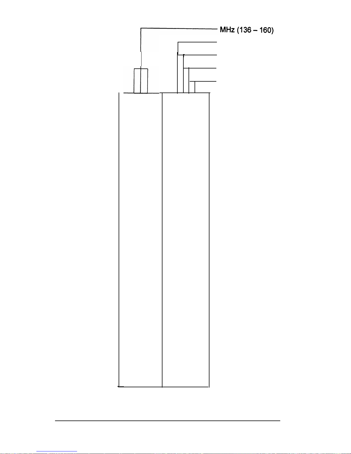
lOOkHz(O-9)
_IID
xxx.
x000
050
100
125
150
200
250
300
350
375
400
450
500
550
600
625
650
700
750
800
850
875
900
950
v
lOkHz(O-9)
1
kHz(0,2 or5)
1kHz(O or 5)
I
Table
1. Proper Frequency Increments.
18
Page 20
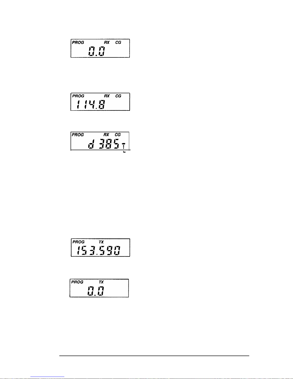
4.
After the Receive Frequency is set,
the upper part of the display will
show
PROG
RX CG. This is the
Code Guard value for Channel 1
receive. Note: 0.0 indicates carrier
squelch operation.
If the displayed value is correct, press
FCN
to advance to the next value.
If a new value is desired, press the
CLR
key to reset the display to 0.0.
Tone Code Guard is entered directly,
using the digit keys (0 through 9).
See pages 21 and 22 for proper
Code Guard values.
Digital Code Guard is entered by
first pressing
CLR,
then the # key,
causing the letter d to appear,
L INDICATES
INVERTED
followed by the proper three digit
CODE
code (0 through 7 keys only; 8 & 9
respond as a 7). Pressing the
PRI
key after the three digit code has
been entered allows the digital code
to be inverted.
VVhen
the displayed
value is correct, press
ENT
to store
the Code Guard and automatically
advance to the next value.
5.
After the receive Code Guard is set,
the upper part of the display will
show
PROG TX.
This is the
Transmit (TX) Frequency for
Channel 1. If it is correct, press
FCN
to advance to the next value.
To program or change it, press
CLR
followed by the frequency in (MHz)
and then ENT to store the new
NO TRANSMIT FREQUENCY
frequency and automatically
.
advance to the next value.
Only frequencies from 136 to 160
MHz in increments of 5 or 12.5 kHz
will be operable. See Table 1 on
page 18 for proper frequency
increments.
EPI 3101A User’s Manual
19
Page 21
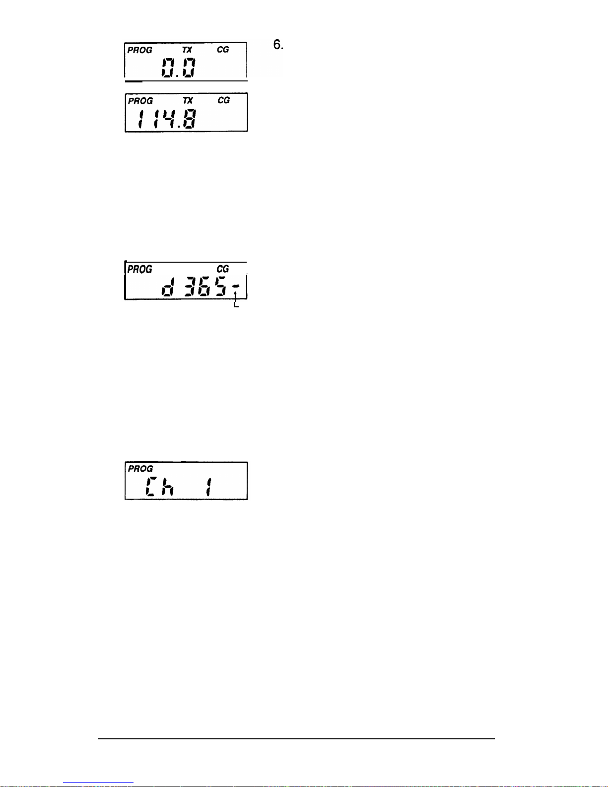
PROG
7x
CG
I
L INDICATES
INVERTED
CODE
7
.
8
.
After the Transmit Frequency is set,
the upper part of the display will
show
PROG TX
CG. This is the
Code Guard value for Channel 1
transmit (0.0 indicates carrier
squelch). If this value is correct,
press
FCN
to advance to the next
value.
If a new value is desired, press the
CLR
key to reset the display to 0.0.
Tone Code Guard is entered directly,
using the digit keys (0 through 9).
See page 21 for proper Code Guard
values.
Digital Code Guard is entered by
first pressing
CLR,
then the # key,
causing the letter d to appear,
followed by the proper three digit
code (0 through 7 keys only; 8
&
9
respond as a 7). Pressing the
PRI
key after the three digit code has
been entered allows the digital code
to be inverted.
VVhen
the displayed
value is correct, press
ENT
to store
the Code Guard and automatically
advance to the next value.
After the transmit Code Guard is set,
the display will loop back to the
Channel 1 entry point. If you wish to
review the frequencies and Code
Guard values in Channel
1,
subsequent pressing of the
FCN
key will show each value and then
loop back to the Channel 1 entry
point again.
To program another channel, return
to Step 1 on page 17 and key in the
desired channel’s number.
TO LEAVE THE PROGRAMMING MODE:
1.
Rotate the OFF/Volume knob on top of the radio counterclockwise to the OFF position.
2.
Normal radio operation will occur the next time the radio is
turned on.
20
Page 22

SELECTING A TONE CODE GUARD
The Tone Code Guard system (CTCSS) may be set for any frequency
in the range of 67 to 250.3 Hz. However, since most systems adhere
to the Electronic Industry Association (EIA) standards, tones should be
selected from the following EIA list.
In order to insure optimum performance tone selection for use on the
same radio frequency (RF) channel or adjacent channels in the same
coverage area should be made from one of the Groups A, B, or C as
much as possible. RELM guarantees optimum receiver performance
only if tone frequencies below 220 Hz are chosen.
GROUP A GROUP B
GROUP C
67.0
77.0
88.5
*100.0
107.2
114.8
123.0
131.8
141.3
*151.4
71.9
146.2
74.4
162.2
82.5
156.7
79.7
173.8
94.8
167.9 85.4
186.2 103.5
“179.9
91.5
203.5
100.9 192.8
218.1
*118.8 210.7
233.6
127.3
225.7
250.3 136.5 241.8
*
50/60 Hz power distribution systems could cause falsing.
The assignments in a given area shall be made from one of the
Groups A, B, or C as much as possible.
EPI
3101A
User’s Manual
21
Page 23

SELECTING A DIGITAL CODE GUARD
Codes for the Digital Code Guard system (CDCSS) may be chosen from
the following list. For the performance or compatibility of Digital Code
Guard systems, it is recommended that an operational test be made on
the intended system before wholesale assignments are made.
In some cases, either one or both the transmit and receive codes will
require an inverted code* to operate with existing systems. This can be
done during the code programming of the system.
Usually, systems using direct unit to unit transmission (systems without
mobile relays, repeaters, remote control, etc.) may use codes from the
table. Systems with relays, etc. may use code variations for system
control and operational efficiency. The system operator or engineer
should be consulted regarding the operational requirement on such
systems.
023
065 131 172 251 331 412 466 612 703
025
071
132 174 261 343 413 503 624 712
026
072 134 205 263 346 423 506 627 723
031
073 143 223 265 351 431 516 631 731
032
074 152 226 271 364 432 532 632 732
043
114 155 243 306 365 445 546 654 734
047
115 156 244 311 371 464 565 662 743
051
116 162 245 315 411 465 606 664 754
054
125 165
*NOTE:
Inverted code is displayed with a
"-"
following the Digital
Code’s value. See page 20 for an example.
22
Page 24
CLONING
STANDARD INSTRUCTIONS
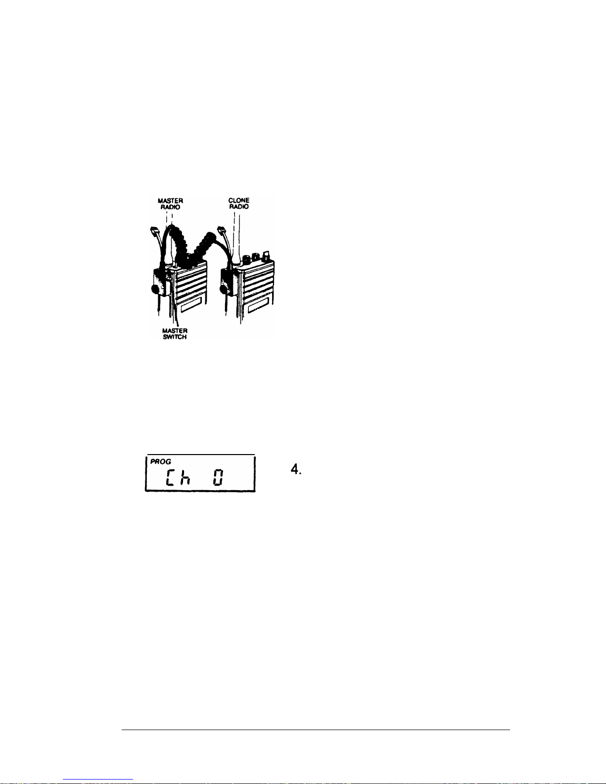
Any MASTER radio (an EPI 3101A with the desired radio frequencies
and settings) is capable of transferring its program to another EPI 31
01A
or SLAVE. The radio receiving the program also is referred to as the
CLONE. The LAA0700 Cloning Cable will be required in the following
procedure.
1
.
2
.
Make sure that the battery packs for
both radios are charged.
Attach the MASTER switch end of
the cloning cable to the side
connector of the MASTER radio.
(Note: one plug of the cloning cable
has a push button MASTER switch.
This plug must be attached to the
MASTER radio.)
3.
Power up the MASTER radio by
rotating the off/volume knob
clockwise past the detent.
5
.
6
.
7
.
IMPORTANT:
The MASTER and
CLONE radios must be set to the
same Channel Group before cloning
is started. Do NOT clone Channel
Group 01 to Group 02 or vice versa.
To put the MASTER radio in the
programming mode, press and hold
the MASTER switch. Then press
the
FCN
key until the display shows
PROG Ch 0.
Review the values in the program.
Any changes required must be made
at this time.
Connect the other plug of the cable
to the side connector of the radio to
be cloned.
Power up the CLONE and set it to
the proper Channel Group.
EPI 3101A User’s Manual
23
Page 25
8
.
9
.
Press the * key on the MASTER
radio keyboard. The display will flash
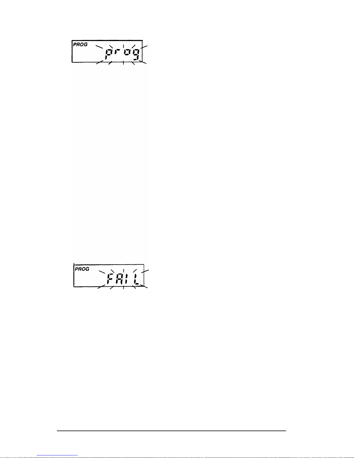
PROG
signifying that the radio is
ready to download its program to the
CLONE.
Press the
FCN
key on the MASTER
radio keyboard. The program in the
MASTER will then be downloaded
to the CLONE. The CLONE will
automatically send back the program
to the MASTER to verify a successful
cloning.
10. If the download was successful, the
MASTER’s display will resume
flashing
PROG.
A. To clone the other Channel
Group, power down both radios
and go to Step 3, changing the
Channel Group as required.
B.
If finished cloning, power down
the CLONE and disconnect the
cloning cable. Normal radio
operation will occur on the
CLONE’s next power up.
11. If the download was not successful,
the MASTER will display
FAIL
and
multiple beeps will follow. Failure of
downloading can be due to:
A. Improper connection
B.
Failure to power up CLONE
C.
CLONE set in the programming
mode
NOTE: To stop the FAIL mode,
press
CLR,
power down both radios
and try again, starting at step 1 on
page 23.
24
Page 26
SPECIAL CLONING INSTRUCTIONS
It is possible to change Channel 0 values on the MASTER radio, hold
them in a temporary memory, and download them to the CLONE without
actually entering them into the permanent memory of the MASTER. This
is convenient if sequential identification numbers are used to identify a
series of portables in a radio system. Assuming that the frequencies,
Code Guard values, and other CH 0 values are common for all radios in
the system, but that the radio identification number should be unique to
each radio, the following method would be used to clone additional radios
for the system:
1
l
2
.
3
.
4
.
5
.
6
.
Program the MASTER with all
frequencies, Code Guard values and
Channel 0 values that will be
common to all radios.
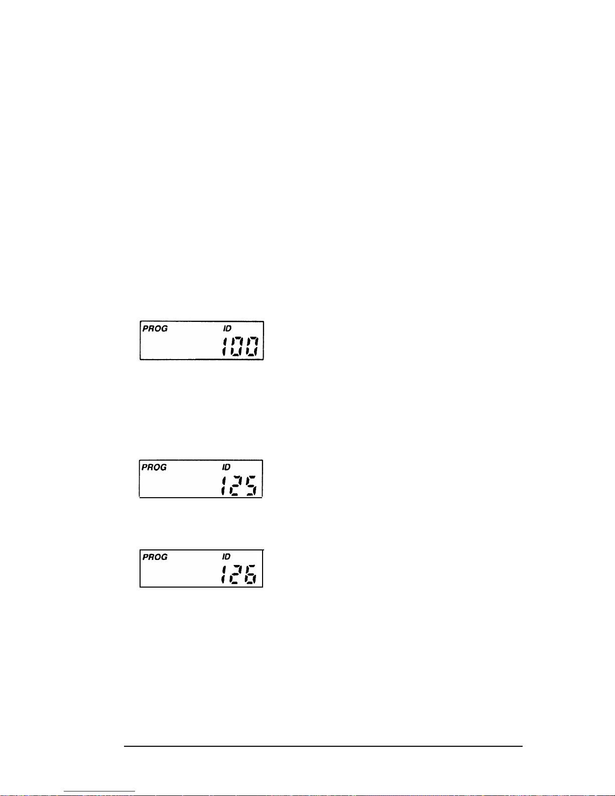
Advance the display to show the
MASTER’s ID number (for example
100)
.
Press
CLR;
press
1,2,
and 5.125 is
now only in temporary memory.
Press *, connect the cloning cable to
the CLONE radio and download by
pressing
FCN.
ID number 125 is
now stored in permanent memory of
the CLONE.
After download, press
CLR.
Disconnect the CLONE. The
MASTER radio display will show
that
125
is still being held in the
temporary memory of the MASTER.
Press
PRI.
This will increment the
ID number one digit to
126.
NOTE: Any new number can be
entered at this point by pressing
CLR and using the digit keys to
enter the new number.
EPI
3101A
User’s Manual
25
Page 27

7.
Press *. Connect the cloning cable
to the next CLONE radio and
download by pressing FCN.
8.
Any number of radios can be coded
with different or sequential ID
numbers using this technique. The
ID number in the permanent memory
of the MASTER will remain
unchanged as 300.
PROGRAMMING FROM A COMPUTER
Programming the radio from an IBM compatible computer, using the
LAA0725 Interface Cable, is covered in a separate programming manual.
The manual is included with the programming software. Contact RELM
Communications, Inc. to order the interface cable and software. Specify
the program is for the EPI 3101A Radio.
26
Page 28
ACCESSORIES
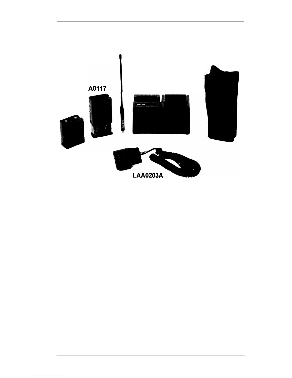
The accessories shown are part of the AN/PRC-127(A) Radio Set.
I
LAA0818A
LAA0445A
LA
LAAO126
LAA0312A
LAA0312A
Desktop Charger
Rapidly recharges the LAA0126 battery pack to 90% of capacity, then
switches to a trickle rate to maintain the charge without damaging the
battery pack. Red and Green LED indicators confirm proper contact with
the battery and show the charge rate. An input voltage selector switch,
located on the bottom panel, allows for either 115 VAC or 230 VAC
operation. The proper selection should be made before the Charger is
plugged into the voltage source.
LAAO126 Nickel-Cadmium Battery Pack
High capacity (1200 mAH) rechargeable battery pack. Two packs (one
spare) are shipped with the Radio Set.
LAA01
17 Battery Holder
Allows the use of replaceable AA alkaline batteries when recharging of
the LAA0126 battery pack is not available. The Holder, as shown, is only
partially opened. Slide the cover all of the way up in order to install the
9 batteries. Then slide it back down until it snaps in place.
EPI 3101A User’s Manual
27
Page 29

Helical-wound flexible antenna that covers the entire range of frequencies
that can be programmed into the EPI 3101A Radio.
LAA0445A Carrying Case
This textile case is built to provide proper protection while keeping the
radio at your side.
LAA0203A Speaker/Microphone
This light weight speaker/microphone clips securely to collar or lapel,
offering the convenience of easy communications without removing the
radio from your belt. To install the LAA0203A:
1.
Lift away the protective cover from the Accessory connector and
Earphone jack. See Radio’s side view on page 3 for their
location. The protective cover can not be completely removed
since it is permanently attached near the flexible antenna’s
connector.
2.
Carefully install the Speaker/Microphone’s connector assembly
into the Accessory and Earphone connectors.
3.
Screw in the assembly’s retaining bolt until finger tight. Do not
overtighten.
NOTE:
VVhen
the LAA0203A is removed, the protective cover
should be reinstalled so that the various electrical
connections are not exposed to dust, dirt, rain, etc.
28
Page 30
RELM Communications, Inc.
7505 Technology Drive
West Melbourne, FL 32904
Telephone: (407) 984-1414
FAX: (407) 676-4403
0
Copyright 1997 RELM Communications, Inc. All rights reserved
P/N 700 I-20257-900
1-97
 Loading...