

Canada
, and meets all requirements of the National Electrical Code.
Transfer switches are required for use with portable
Reliance Controls Corporation is
Member of the National Electrical Manufacturers Ass
ociation
STANDBY POWER FURNACE SWITCH
Easy/Tran®
TF151, TF151W, TF201 and TF201W
Congratulations on your purchase of the Reliance Controls Easy/Tran TF furnace transfer switch. Reliance has
been manufacturing transfer switches and equipment in Racine, Wisconsin since 1982 and has been producing
high-quality electrical equipment for nearly 100 years. Reliance is the Loadside® transfer switch used in nearly
90% of the installations done by professional electricians. Your transfer switch is UL 1008 listed, for the U.S. and
TOOLS NEEDED FOR INSTALLATION
1. Power Drill 6. Tape Measure
2. Wire Stripper and Cutter (10 to 14 gauge) 7. Three Wall Anchors
3. Insulated Screwdrivers 8. Battery Powered Lighting during Installation
(#2 Phillips, ¼” Flat Tip or #2 Square Tip 9. A Non-Contact Voltage Detector (optional)
depending on your load center)
4. Hammer
5. Marking Pencil
PARTS LIST for Easy / Tran
TF
FURNACE TRANSFER SWITCH
15 Amp (TF151) or 20 Amp (TF201) Single-Circuit Transfer Switch
5 Yellow Wire Connectors
SAFETY SYMBOLS USED IN THIS MANUAL
Danger indicates an imminently hazardous
situation that, if not avoided, could result in
death or serious injury.
Warning indicates a potentially hazardous
situation that, if not avoided, could result in
death or serious injury.
Caution indicates a potentially hazardous
situation that, if not avoided, may result in
minor or moderate injury.
generators by Article 702 of the National Electrical Code
not responsible for damage or
injury caused by incorrect
installation of this transfer switch.
switch could cause damage or personal injury by
electrocution or fire. Installation must be performed
by a qualified electrician, or others knowledgeable of
electrical systems, in compliance with all applicable
electrical codes.
this manual should not be used for electric water
heaters, clothes dryers, electric ranges, central air
conditioners or other appliances or systems that may
exceed the capacity of the product.
Improper installation of the transfer
Reliance transfer switches covered in
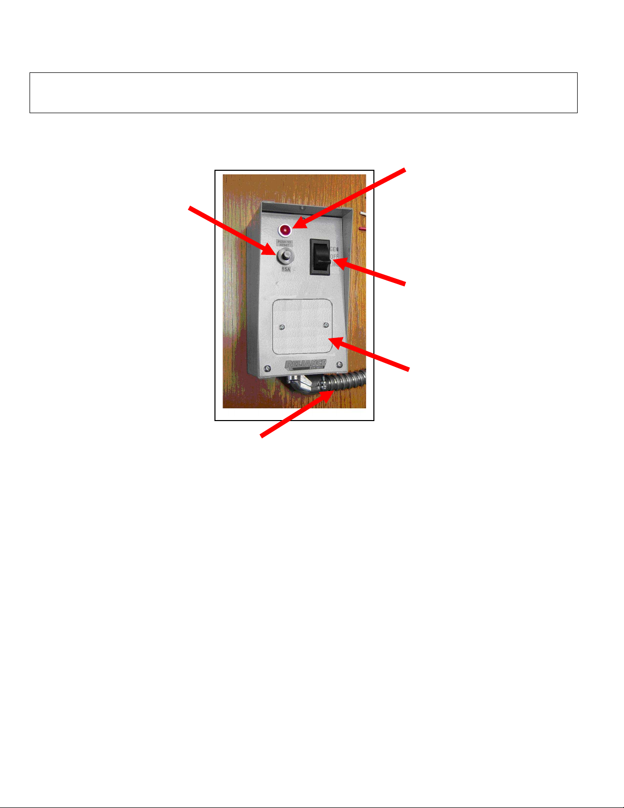
Branch
-
Rated Circuit Breaker
Toggle Switch
Pre-Wired Flexible Conduit Whip
Page 2
Panel Light
Cover Plate
KEY COMPONENTS OF THE RELIANCE CONTROLS FURNACE TRANSFER
SWITCH FOR PORTABLE GENERATORS
The circuit breaker is either a 15 Amp
(TF151) or 20 Amp (TF201) push-to reset
branch-rated circuit breaker that protects
the branch circuit when the toggle switch
is in the GEN position. In the LINE
position, the branch circuit is protected by
the furnace breaker in the load center
Contains two hot, one neutral and one ground wire
required to make connections between the furnace
transfer switch and the furnace circuit breaker in
your load center. Each wire is color-coded for easy
identification. Conduit and fittings not supplied on
.
This light is powered by the generator
only
This switch allows you to select either
GEN (generator) or LINE (utility) as the
power source for the furnace circuit
breaker that has been wired through the
transfer switch. The OFF position
generally is not used, as a switch in the
OFF position removes the furnace circuit
both from generator and utility power

INSTALLATION INSTRUCTIONS
Even with the main power switch
injury or death.
Figure 2
Even with the main power switch turned
I. Mounting the Easy/Tran
A.
Loosen the front plate by removing one screw on the front and
loosening the two screws on the bottom. Tilt the front plate forward
to access the mounting holes in the back of the cabinet.
B.
Position the Easy/Tran TF in the desirable location. When mounting
the suffix W model next to an electrical panel, position so that its
bottom center is about 18 inches from the bottom center of your load
center. The end of the flexible conduit whip should be lined up with
a 1/2” knockout hole on the bottom of your load center (Figure 2).
C.
Mark the position of the three mounting holes of the transfer switch
with a pencil.
D.
Secure the EasyTran TF to the mounting surface using appropriate
anchors.
E.
When feeding the generator power from a power inlet box (sold
separately), follow the installation instructions provided with the
power inlet box. Select a convenient knockout on one of the sides of
the transfer switch. Run building wire or Romex®, (purchased
separately) as approved by local electrical code, from the power inlet
box to the transfer switch. Use three of the yellow wire connectors to
connect the leads in the transfer switch to the wire from the power
inlet box. Connect the black wire from the transfer switch to the
black wire from the power inlet box; connect the white wire in the
transfer switch to the white wire from the power inlet box: connect
the green wire in the transfer switch to the green wire from the
power inlet box.
F.
Tilt front plate back into the cabinet and attach with the screws in
Step 1.
II. Connecting Models TF151 and TF201
®
Page 3
Typical
Main
Breaker
Location
Live Wires on
Utility Side of
Main Breaker
These models should be connected by a licensed electrician or heating
contractor since they involve mounting on the furnace and making the
electrical connections on or in the furnace instead of the electrical panel.
Connect the wires from Easy/Tran to the furnace as follows:
A.
Black wire to the wire or wires that power(s) the furnace.
B.
Red wire to the wire coming from the branch circuit breaker.
C.
White wire to both the neutral wire to the furnace and the neutral
wire from the electrical panel.
D.
Green wire to the grounding point in the furnace.
III. Connecting Models TF151W and TF201W
A. Connecting the Flexible Conduit Whip to Your Load
Center
its structural capabilities.
1.
Set up battery-powered lighting to clearly illuminate your work area.
2.
Turn off the main utility breaker (Figure 3).
3.
Remove the cover of your load center. Keep in mind that the wires
on the utility side of the main breaker are still live and if contacted
could cause serious injury or death. If available, use a non-contact
voltage detector to insure that the power is off on the non-utility side
of the main breaker.
4.
Remove the appropriate knockout hole in the bottom of your load
center with a screwdriver and hammer. (See step I-B above.)
5.
Insert all four of the wires extending from the end of the flexible
conduit whip through the knockout hole. Fasten the conduit
connector attached to the whip into the knockout hole using the nut
provided.
– Be careful not to bend the flexible conduit whip beyond
turned off, the wires on the utility side
of the main breaker are still live and
contact with them can cause serious
off, the wires on the utility side of the main
breaker are still live and contact with them
can cause serious injury or death.
To Transfer Switch
Conduit
Connector
Figure 3

Figure 4
Switch A
Wires from
Ground Wire
Wires from
C. Connecting the Neutral and Ground Wire
Strip approximately 5/8” from the end of the white wire.
IV. Finishing Up
1.
Find the white wire (Neutral) and the green wire
(ground) among the wires from the transfer switch that
you have inserted into the load center.
2.
Locate the neutral bar and partially unscrew a terminal
screw on the bar. Insert the stripped end of the wire
into the side of the bar under the screw and retighten
the screw. (Figure 4)
3.
Locate the ground bar. (It should be labeled.)
Connect the green wire to the ground bar in the same
way as in step #2. In service entrance load centers,
the ground bar and neutral bar are frequently the
same; if so, the ground and neutral wires can be
connected to either.
D. Connecting a 120 Volt Furnace Circuit
1.
Turn off the furnace circuit breaker. Disconnect the
wire that is attached to it.
2.
Find the black and red wires from the Easy/Tran TF.
3.
Cut the red wire at a length convenient for it to reach to
the furnace circuit breaker. Strip 5/8” from the end of
the wire. Connect the red wire to the furnace circuit
breaker and retighten the screw on the breaker.
4.
Cut the black wire from the transfer switch to a length
convenient for attaching it to the wire you removed
from the furnace circuit breaker in #1. Strip 5/8” from
the end of the wire.
5.
Insert both wires—the one removed from the furnace
circuit breaker and the black wire from the furnace
relay—into a yellow wire connecter. Tighten the
connection and push the connected wires back into the
wiring compartment of the load center.
This completes the wiring of the Easy/Tran TF.
Proceed to Section IV.
Page 4
Furnace
After you have completed the steps in Sections I through
III, complete the installation by doing the following:
A.
Turn the furnace circuit breaker in your load center
back on.
B.
Turn on the main breaker.
C.
Position the toggle switch on the Easy/Tran TF to the
LINE position.
.
Wires from
Switch
Figure 5
(Green)

OPERATING INSTRUCTIONS
TF151 &
TF151
W TF201 &
TF201
W
You want your generator to be ready when you need it -- so, it is important to perform the following steps once a month:
•
•
With your Reliance Controls Easy/Tran TF installed, it is not necessary to turn off any of your load center breakers when starting
your generator, even when utility power is fully functional. This is because the double throw break-before-make action of the furnace
relay prevents feeding generator power to the utility and, conversely, prevents feeding utility power back to your generator.
A. Transferring from Utility Power to Generator Power in an Emergency
1.
2.
3.
4.
5.
B. Transferring back to Utility Power When the Power Is Restored
1.
2.
3.
Maximum Watts
Maximum Combined Load @ 125 Volts AC (Amps)
Maximum Load per Circuit from Generator (Amps)
Maximum Load per circuit from Load Center (Amps)
Wattmeters
Number of Knockouts Available 1/2" or 3/4"
Cabinet Dimensions H x W x D (inches)
Cabinet Type (NEMA)
Start and run generator power through your transfer switch circuits.
Keep your fuel tank filled with fresh fuel.
Make sure that the toggle switch on the Easy/Tran TF is in the LINE position.
Plug the appropriate extension cord into the appropriate receptacle on your generator.
Plug the female end of the extension cord into the power inlet box.
Start your generator outdoors and let it warm to a point where it is running evenly.
Turn the toggle switch on the furnace relay to the GEN position.
Move the toggle switch on the Easy/Tran TF back to the LINE position.
Turn off your generator.
Unplug the extension cord.
SPECIFICATIONS
1875 2500
15 20
15 20
20 20
No No
2 2
7 1/2" x 7" x 4 1/2" 7 1/2" x 7" x 4 1/2"
1 1

Five Year Limited Warranty
Reliance Controls Customer Service: (800) 439
-
5745
7/6/10
Reliance Controls Corporation (“Reliance”) warrants this Protran® Manual Transfer Switch (“Switch”) to be free from failure to perform as
intended due to defects in materials and workmanship for a period of five (5) years from date of manufacture, provided the Switch has been
installed and used in accordance with manufacturer’s instructions and has not been subjected to misuse, alteration, accident, or repair not
performed by Reliance. If, within such warranty period, the original purchaser gives written notice to Reliance at the address shown below and
the Switch has been proven to Reliance’s reasonable satisfaction to be defective, then Reliance at its sole option shall either: (i) supply a
replacement component(s) for the defective component(s) or (ii) repair or replace the Switch. Reliance’s obligation is strictly limited to said repair
or replacement of the Switch and Reliance shall not be liable for any incidental, special or consequential damages. The cost of labor to remove or
install a replacement component or Switch is not included in this warranty. The foregoing warranty is exclusive and in lieu of all other expressed
or implied warranties, if any, including but not limited to implied warranties of merchantability and fitness for a particular purpose. Reliance
strongly recommends that the purchaser seek the advice of a licensed electrician to determine the suitability of this product, and for its proper
installation in accordance with all applicable state and local building codes. This warranty gives you specific legal rights, and you may have other
rights which vary from state to state.
Website: www.reliancecontrols.com
 Loading...