

INSTALLATION AND OPERATING
INSTRUCTIONS
Q-Series
MANUAL TRANSFER SWITCHES
FROM
0

Residential Wattage Requirements
Appliance
Furnace blower, gas or fuel
1/8 hp 300 500
1/8 hp 500 750
1/6 hp 500 750
1/4 hp 600 1000
1/3 hp 700 1400
1/2 hp 875 2100
Shallow well pump
1/3 hp 750 1400
1/2 hp 1000 2350
Sump pump
1/3 hp 800 1300
1/2 hp 1050 2150
Refrigerator or freezer 800 2300
Garage door opener
1/4 hp 550 1100
1/3 hp 750 1400
Running
Watts
Add watts
for starting
Lights on bulb 0
Radio 50-200 0
Television 100-300 0
Microwave oven 600-1500 0
Coffee maker, typical 1750 0
Toaster/toaster oven 1050-1850 0
Portable heater 1100-1500 0
Dehumidifier 650-800 0
Electric blanket 400 0
Clothes washer 1150 2300
Clothes dryer, gas 700 1800
Dishwasher
cool dry 700 1400
hot dry 1450 1400
Vacuum cleaner 800-1100 0
Hair dryer 300-1500 0
Iron 1200 0
1
y
g
Warnings • Cautions
Warning: Improper installation of this transfer switch
could cause damage or personal injury by electrocution
or fire. Installation must be performed by a qualified
electrician in compliance with all applicable electrical
codes
Caution: Reliance transfer switches covered in this
manual should not be used for appliances or systems
that ma
Caution: When the transfer switch is connected to
branch circuits with AFCI or GFCI breakers, the AFCI
or GFCI protection will be lost when, and only when,
the toggle switch in the transfer switch is in the GEN
position. To get AFCI or GFCI protection when running
on
exceed the capacity of the product.
enerator power, it must be provided at the outlet(s).
Reliance Controls Corporation is not responsible for
damage or injury caused by incorrect installation of
this transfer switch.
Member, National Electrical Manufacturers Association
1
g
A
A
r
Reliance Installation and Operating Instructions
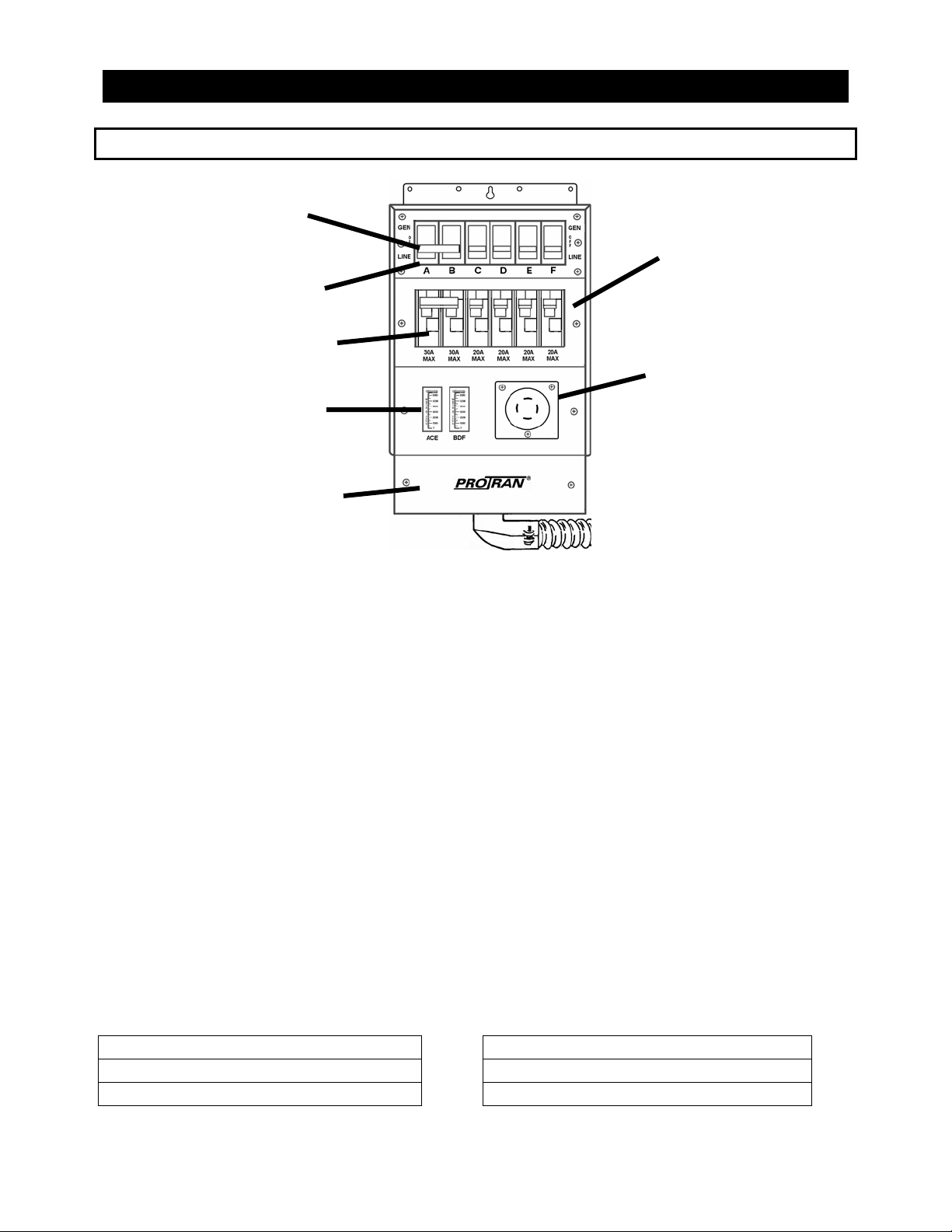
Key Components of the Reliance Transfer Switch
Handle tie
Circuit Selector Switches
Circuit Breakers
Watt meters
(select models only)
Wiring Compartment
Cover
Circuit Breaker
Compartment Cove
Power Inlet
(cord-connected
models only)
Figure 1
Circuit breakers. Each transfer switch circuit has a 1-in interchangeable circuit breaker
that protects the branch circuit when the circuit selector switch is in the GEN position. In
the LINE position, each branch circuit is protected by the breaker in the load center.
Circuit selector switches. These switches allow you to select either GEN (generator) or
LINE (utility) as the power source for the branch circuits that have been wired through the
transfer switch. The OFF position is generally not used, as a switch in the OFF position
removes that branch circuit from both utility and generator power.
Handle ties. Handle ties are used for 240-volt circuits or multi-wire branch circuits. They
may be removed for 120-volt circuits. See page 6 for instructions on removing and adding
handle ties.
Power inlet (selected models only). The power cord from the generator is plugged into
this inlet. Not needed for hard-wire installation with remote power inlet box.
Power inlet filler plate. Models without the power inlet installed have a filler plate
covering the hole in the wiring compartment cover. This can be replaced with a power
inlet. Models with a power inlet installed have a filler plate included in the unit carton. This
can replace the power inlet for hard-wire installation.
Wiring Compartment Cover. All models include a wiring compartment that can be used
to hard-wire the unit to a remote power inlet box.
Analog wattmeters (suffix -A and -C models). These meters indicate the total load, in
watts, on each side of the generator when the generator is supplying power as follows:
The left meter measures the load on The ri
, C, and E 6-circuit B, D and F 6-circuit , C, E, G and I 10-circuit B, D, F, H and J 10-circuit
Note: The watt meters will register only if power is being used from the generator.
ht meter measures the load on
2
Electronic wattmeter (suffix -AE and -CE models). Two sets of LED readouts (a long
and a short) appear on the face of the meter. The left set applies to the circuits shown in
the left box above, with the longer scale indicating the total wattage supplied from the
generator to those circuits, and the shorter scale indicating the relative generator output
voltage on those circuits. In a similar manner, the right set applies to those circuits shown
in the right box above. A green readout indicates that voltage and amperage are within
an acceptable range. In addition, a “mains on” indicator appears in the upper left corner,
and will be lit when utility power is available and the main circuit breaker in the load center
is in the “on” position. The generator must also be connected and running for the “mains
on” indicator to operate properly.
Installation Instructions
Preparing for Installation
You will need the following items:
Electric drill
Screwdriver
Wire cutters/stripper
Hammer
Four anchors and screws
6 or 10 yellow wire connectors (depending on the model)
4 red wire connectors for the 20A and 30A hard-wire models
The following five steps generally apply to all transfer switch installations. The transfer
switch may be installed on either side of the load center.
1. Turn off the main circuit breaker in the load center to ensure your
safety.
2. Remove the cover of the load center.
3. Locate and remove a knockout (ko)
in the bottom of the load center
(Figure 2). Use a 3/4" ko for 6-circuit
models, and a 1" ko for 10-circuit
models.
4. Insert the wires extending from the
end of the flexible conduit through
the ko. Attach the conduit connector
securely with the locknut provided.
5. Anchor the transfer switch to the wall
using the top bracket and bottom
mounting holes located in the
cabinet behind the wiring
compartment cover. Do not attempt
Danger: All current-carrying parts on the LINE side of the main
are still live
3
Figure 2

to bend the flexible conduit beyond
its structural capabilities
.
Wiring the Reliance Transfer Switch to the Load Center
Determine which circuits will be used during an emergency. The residential wattage
requirement chart on the inside front cover of this manual may be used as a guide, but
actual appliance wattages may vary. If a selected circuit is part of a multi-wire branch
circuit, ensure the other branch circuit that shares the neutral is also connected to the
transfer switch. The two circuits must be connected to opposing legs (phases) of the
generator power and a handle tie must be installed on the switch handles so that both legs
are transferred at the same time.
The maximum number of circuits available and those that can be used for multi-wire
branch circuits depends on the model of the transfer switch as follows:
Model Max Available for mu lti-wire branch circuits
Q206, Q306, Q506 6
Q310, Q510 10 Any two adjacent circuits.
Warning: Failure to properly install a multi-wire branch circuit could result in
overloading the neutral wire.
Any two adjacent circuits.
Balancing the Load
To maximize the efficiency of your generator, divide
appliance circuits and others requiring higher wattage
between adjacent circuit selector switches of the transfer
switch so that a usage balance is achieved between the
opposing legs of the generator power.
For example, on a 6-circuit transfer switch, consider wiring
the refrigerator to Switch A and the furnace to Switch D
(Figure 3).
Figure 3
Changing Circuit Breakers
This product is supplied with a combination of 15- and 20-amp circuit breakers. In
some cases, a 30 amp double-pole breaker may be supplied in the A and B positions.
All circuit breaker positions will accommodate 15- and 20-amp circuit breakers, and
may be easily changed in the field. To remove a circuit breaker, remove the circuit
4

breaker compartment cover, unscrew the terminal screw in the breaker to be removed,
removed the wire, tilt the top of the circuit breaker towards you and lift up and out.
Reverse the procedure to install another breaker. In addition, positions A and B (but
only these positions) will accommodate 30-amp circuit breakers.
This product is UL approved for use with the following field-installed breakers:
Siemens Type QP
Square D Type HOM
Eaton Cutler-Hammer Type BR
Murray Type MP
30 amps maximum in positions A and B, 20 amps maximum in all other positions.
Rating of a transfer switch circuit breaker should not exceed the rating of the
corresponding branch circuit breaker in the load center.
Do not install any breaker larger than 20 amps., except in positions A and B
which may be 30 amps.
Installing 120-volt Circuits
Wire the most critical circuits first, starting with any circuit position on the transfer
switch. Let's assume that Switch C will be designated to supply power to the
refrigerator.
1. Turn off the refrigerator circuit breaker. Loosen the screw that secures the wire to the
2. On the transfer switch, find the black and red wires marked C.
3. Feed the red wire to the selected breaker, in this case the refrigerator breaker.
4. Cut the red wire C to a convenient length. Strip approximately 5/8" from the end of the
5. Cut the black wire C to a convenient length for aligning with the wire removed from the
6. Insert both wires (the wire removed from the circuit breaker in step 1 and the black
This completes the installation of the transfer switch for your refrigerator.
Warning: Transfer switch circuits with 20 amp breakers must be installed on only
those branch circuits with 20 amp branch circuit breakers. Transfer switch circuits
with 15 amp breakers can be installed on 15 or 20 amp branch circuits. Do not
install any transfer switch circuit on branch circuits greater than 20 amps,
except in position A and B which maybe 30 amps.
circuit breaker. Disconnect the wire from the circuit breaker.
wire. Connect the red wire to the refrigerator circuit breaker and retighten the screw.
refrigerator circuit breaker in step 1. Strip approximately 5/8" from the end of the wire.
wire) into a yellow wire connector. Twist the connector tightly and push the wires back
into the wiring compartment of the load center.
Repeat steps 1-6 for each of the remaining considering the following:
• See the following section for 240-volt circuits and the removal of handle ties if
240-volt circuits are not required.
• Remember to "balance the load"—dividing the appliances requiring higher
wattage between the left and right sides of the transfer switch.
5

Installing 240-volt Circuits
Any two adjacent circuit selector switches may be used for a double-pole 240-volt circuit.
Use a handle tie to connect the two circuit selector switches.
*Note: Circuits used for multi-wire branch circuits are not available for 240-volt
circuits
Removing handle ties. If there are no 240-volt or multi-wire circuits in the transfer switch
installation, handle-ties on the switches are not needed. To remove a handle tie, place the
handle-tied switch in the GEN position. Loosen the two screws and remove the handle tie.
Adding handle ties. If additional ties are needed to accommodate additional 240-volt
or multi-wire circuits, they can be added to adjacent pairs of switches.
Warning: Transfer switch circuits with 20 amp breakers must be installed on only
Installing 240-volt circuit(s)
1. Locate the two red and two black wires from any adjacent circuit positions.
2. Turn off the double-pole breaker in the load center.
those branch circuits with 20 amp branch circuit breakers. Transfer switch circuits
with 15 amp breakers can be installed on 15 or 20 amp branch circuits. Do not
install any transfer switch circuit on branch circuits greater than 20 amps,
except in position A and B which maybe 30 amps.
6

3. Loosen the screws that secure each wire to each circuit breaker. Disconnect the wires
from the circuit breakers.
4. Feed the two red wires in Step 1 to the double-pole circuit breaker.
5. Cut the red wires to a convenient length. Strip 5/8" from the end of each wire. Connect
the two red wires to the double-pole circuit breaker.
6. Cut the black wires to a length convenient for aligning with wires removed from the
circuit breaker. Strip 5/8" from the end of each wire.
7. Insert one wire removed from the circuit breaker and one black wire into a yellow wire
connector. Twist to tighten and push the wires back into the wiring compartment of the
load center. Do the same for the other wire removed from the circuit breaker and the
other black wire from the transfer switch.
8. Be sure that a handle tie is connected between the two circuit selector switches.
Repeat steps 1-8 for the other double-pole circuits.
30-Ampere Circuits. Only circuits A and B may be used for 30-amp. circuits. Follow the
above wiring instructions for installing 240-volt circuits. If 30-amp. single-pole circuits are
being used, refer to the previous section regarding installation of 120-volt cirucits.
For models with -C or -D suffix, or to hard wire any cord-connected model, continue to the
next section entitled "Hard-wire Installation" to complete the installation.
For all other models, skip to "Completing the installation" on page 8.
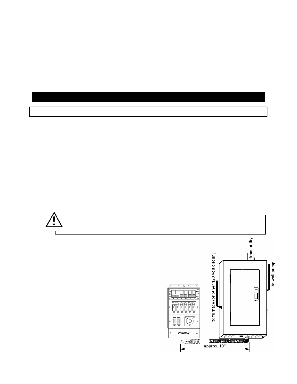
Hard-wire Installation
"Hard-wire" installation to a power inlet box located remotely from the transfer switch (Figure
6) requires additional steps to complete the installation. The wire connections to the wires
from power inlet box are made in the wiring compartment of the transfer switch. Access the
wiring compartment by removing the two screws located on the sides of the lower wiring
compartment cover. Replace when installation is complete. For models with wattmeters, see
wattmeter sections below before making the
following connections.
For models having a terminal block in the wiring
compartment, connect to the remote power inlet
box as follows:
From the transfer switch, connect:
the black terminal to the power inlet X or Y
terminal
the white terminal to the power inlet neutral W
terminal
the red terminal to the power inlet X or Y
terminal
the green terminal to the power inlet ground G
terminal.
7

Certain models have color-coded wire leads instead of a terminal block. Connect the wire
leads to the remote power inlet box using the same color key as used for wiring the terminal
block above (see Figure 5).
Models with suffix -A, -AE, and -B can be hard-wired by removing the power inlet and
connecting the wire leads as described in the preceding paragraph. Install the plastic
cover included with the unit over the inlet opening after the inlet is removed.
Models with Analog Wattmeters (suffix -A and -C). Most of these models are factory
pre-wired. When connecting an analog watt meter equipped transfer switch to either a
power inlet or power inlet box, run
the black wire lead going to the inlet
through the hole in the current
transformer (the small black
doughnut-shaped device) attached
to the left hand meter. Run the red
wire lead through the hole in the
current transformer attached to the
right hand meter. No direct
connection to the meter is
necessary for the meters to function
as described on the bottom of page
2.
Models with Electronic Meter (suffix -AE and -CE). These models are factory prewired
at the terminal block located on the bottom wiring compartment cover.
Completing the Installation
When you have wired all the load circuits in the transfer switch, only the white neutral wire
and the green ground wire remain.
1. Insert the white neutral wire into an unused opening in the neutral bar in the load
center and tighten the screw (Figure 4).
2. Insert the green ground wire into an unused opening in the ground bar, if existing, and
tighten the screw. If no ground bar exists, insert the green wire into an unused hole in
the neutral bar and tighten the screw.
3. Replace the cover to the load center.
4 Fill in the chart on the transfer switch to identify your emergency circuits and
corresponding circuit numbers in the load center.
5 Return all load center branch circuit and main breakers to the "ON" position.
6 Move all circuit selector switches on the transfer switch to the
"LINE" position.
Installation is now complete.
8

Operating Instructions
Using your Reliance Transfer Switch and Your Portable Generator
Warning: Do not operate a generator in an enclosed area.
Do not operate a generator where the exhaust
fumes can accumulate in an enclosed area.
You want your generator to be ready when you need it. Therefore, it is important to
perform the following steps at least once a month to keep the generator in peak running
condition.
• Start and run your generator under load regularly.
• Keep the fuel tank filled with fresh fuel.
It is not necessary to turn off any circuits in the load center when supplying generator
power with the transfer switch, even when the utility power is operating normally. The
double-throw action of these switches prevents feeding generator power to the utility and,
conversely, prevents feeding utility power to the generator.
Transferring from Utility Power to Generator Power
1. Plug the female connector of the generator power cord into the power inlet box or the
power inlet on the transfer switch. All circuit selector switches on the transfer switch
should be in the LINE or OFF position.
2. Insert the male plug of the power cord into the outlet on the generator.
3. Start the generator outdoors. Follow the procedures described in the generator
owner's manual furnished by the manufacturer of the generator.
4. Select the circuits to be powered by the generator by moving the corresponding
switches on the transfer switch to the GEN position. Use only necessary household
items when under generator power.
5. Alternate use of larger loads (furnace motors, well pumps, refrigerators, etc.) to
balance the load. See "Balancing the load" on page 4. Do not exceed the maximum
wattage of the transfer switch.
6. A 15 amp. transfer switch circuit breaker will limit that circuit to a maximum of 15 amps
when in the GEN position. If you have moved a circuit selector switch on such a 15amp circuit to the GEN position that controls a branch circuit that normally draws more
than 15 amps, it may be necessary to turn off some of the appliances on that circuit to
avoid exceeding the 15-amp load for that circuit.
7. Determine circuit wattage by using the wattmeters on the transfer switch, or from the
nameplate on each appliance or motor. Very small loads may not be sufficient to
cause a meter to register.
8. Models with suffix -B and -D do not have watt meters. Determine wattage from the
nameplate on each appliance or motor.
9. Make a note of any excessive loads. These loads must be turned off during
generator operation.
9

Transferring from Generator Power to Utility Power
1 1
15 15
1. Return all circuit selector switches to the LINE position.
2. Follow the procedures in the generator owner's manual to turn off the generator.
3. Unplug the power cord.
Notes on Models Without Watt Meters
If there are no watt meters for checking appliance or motor load, check the nameplate on
each appliance or motor and note the load for each.
The total running wattage for each of these models is as follows:
Model Q206
Models Q306, Q310
Models Q506, Q510
5000 watts
7500 watts
12500 watts
During an emergency situation with the generator running, the circuit selector switches
should be in the OFF or LINE position when a particular load is not needed. Failure to limit
the total load to the total running wattage may cause the generator to stall or create an
undervoltage condition that could damage an appliance motor.
Specifications and Parts List
Model # Q206 Q306 Q506 Q310 Q510
Max. Watts 5000 7500 12500 7500 12500
Max. single-pole circuits 6 6 6 10 10
Max. double-pole and multi-wire
circuits
# of handle ties provided 1
Max. combined loads @ 125
VAC
3 3 3 5 5
2 2
40A 60A 100A 60A 100A
Max. combined loads
20A 30A 50A 30A 50A
@250VAC
Max. load/circuit from generator
Max. load/circuit from load
center
Power inlet, NEMA*
configuration
2-30A
4-20A
2-30A
4-20A
2-30A
4-20A
2-30A
4-20A
2-30A
4-20A
2-30A
4-20A
L14-20 L14-30 CS6375
non-NEMA
2-30A
8-20A
2-30A
8-20A
2-30A
8-20A
2-30A
8-20A
L14-30 CS6375
non-NEMA
Minimum cord gauge AWG 12 AWG 10 AWG 6 AWG 10 AWG 6
No. of conductors (wires) 4 4 4 4 4
Conduit length 18” 18” 18” 18” 18”
Conduit, trade-size diameter ¾” ¾” ¾” 1” 1”
Optional Power Inlet Catalog # PB20 PB30 PB50 PB30 PB50
Shipping weight (lbs) 15
Dimensions (H x W x D) 13 x 7 ¾ x 4 ½ 13 x 11 ¾ x 4 ½
23 23
*National Electrical Manufacturer's Association
10

Transfer Switch Parts List
3
Description Part# Description Part#
Circuit breaker, 15 A S.P. 8491 Power inlet, 20 A L1420F
Circuit breaker, 20 A S.P. 8492 Power inlet, 30 A L1430F
Circuit breaker, 20 A D.P. 8493 Power Inlet, 50 A LL550F
Circuit breaker, 30 A D.P. 8494 Handle tie 6295
Wattmeter, 20 / 30 A 7230
Wattmeter, 50 / 60 A 7231
Current Transformer (C.T.) 7222
Power Inlet Filler Panel 6271
Electronic Meter 7201
Electronic Meter C.T. 7223
Switch, 30A SPDT 7801
Optional Accessories
Power Inlet Boxes
Ideal for installations where the house electrical panel is located
indoors. No need to run the power cord from the generator to the
transfer switch through a door or window. This weather-tight power
inlet box can be mounted on the exterior of the house. Run wiring
through the wall from the inlet box to the transfer switch installation
inside. The generator power cord may then be plugged into the
power inlet box.
Catalog#
PB20 L14-20 4-wire weather-tight male Q206
PB30
PB50 CS6364 4-wire weather-tight male Q506 and Q510
Connector
configuration
L14-30 4-wire weather-tight male
Inlet description For use with models
Q306 and Q310
Power Cords
These heavy duty cord sets are the connecting link
between the generator and the Reliance transfer switch or
the power inlet box. The 4-wire locking plug and connector
match up with the power inlet on each Reliance transfer
switch and with the inlet on the power inlet box. Most
portable generators suitable for 120/240 full-power
operation are supplied with either a 20-amp or 30-amp, 4-wire locking receptacle that
accepts the locking plug and connector on each end of the cord set.
11

Reliance Controls Corporation is pleased that you have made the decision to
purchase this product. We have been manufacturing innovative, quality
electrical controls for nearly 100 years. Our products are backed by one of the
best warranties in the industry.
Reliance transfer switches are
Each Reliance transfer switch or accessory is
guaranteed against mechanical or electrical failure due
to manufacturing defects for a period of 24 months
following shipment from the factory. The
manufacturer's responsibility during this warranty
period is limited to repair or replacement, free of
charge, of products proving defective under normal use
or service when returned to the factory, transportation
charges prepaid. Guarantee is void on products that
have been subjected to improper installation, misuse,
alteration, abuse or unauthorized repair. The
manufacturer makes no warranty with respect to the
fitness of any goods for a user's particular application
and assumes no responsibility for proper selection and
installation of its products. This warranty is in lieu of all
other warranties, expressed or implied, and limits the
manufacturer's liability for damages to the cost of the
product. This warranty gives you specific legal rights,
and you may have other rights, which vary from state
to state.
Warranty
12

Reliance Controls Corporation / 2001 Young Court / Racine, Wl 53404
Phone: (800) 634-6155 Fax: (262) 634-6436
© Copyright 2000 Reliance 5/9/05
13
 Loading...