

Reliance Controls PBN Series, PBN15, PBN20, PBN21, PBN30 Installation Instructions Manual
...
IIPBNXX- 111517
POWER INLET BOX
CAT. NO. PBN-Series
INSTALLATION INSTRUCTIONS
IMPORTANT: Installation of this power inlet box and related wiring must be done by a qualified electrician in compliance
with all applicable electrical codes. When used to power a structure, this inlet must be used in conjunction with a transfer
switch. Not for indoor use. When using an engine driven generator, locate the power inlet box away from doors and
windows to avoid the build up of carbon monoxide from the engine exhaust in enclosed areas.
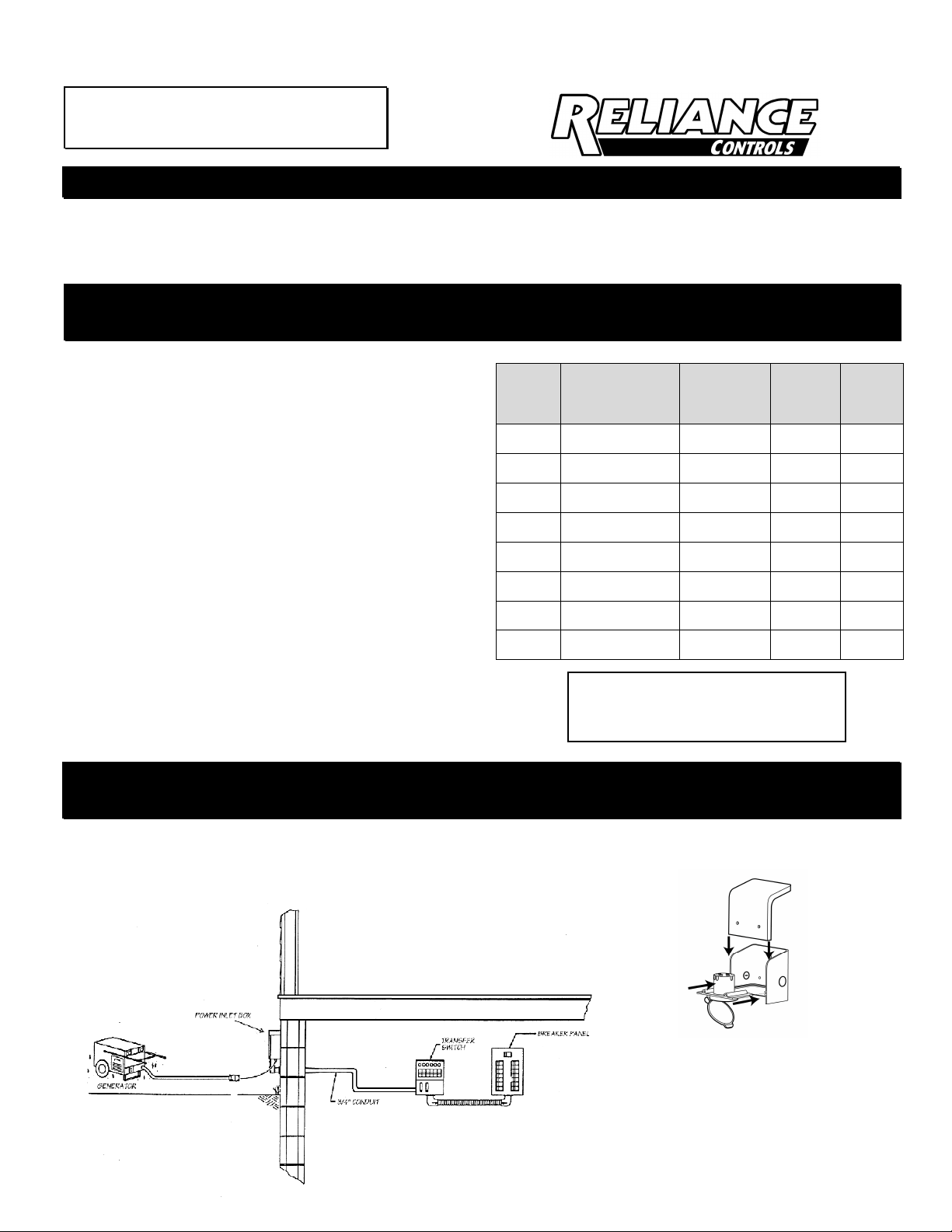
INSTALLING A REMOTELY LOCATED POWER INLET BOX FOR SUPPLYING
POWER TO THE POWER INLET OF A TRANSFER SWITCH OR PANEL
Remove the cover from the Outdoor Power Inlet Box by unscrewing
the two screws on the front of the box with a #2 Phillips
screwdriver. Temporarily slide out the wiring tray. Mount the back
plate of the power inlet box on the outside of the building in a
convenient location, using the three holes provided. Remove one
of the POP-FAST reusable knockouts from the box by pushing out
from the inside of the inlet box. Using copper building wire only
and approved wiring methods, run the appropriate wires from the
transfer switch wiring compartment through the removed knockout
in the power inlet box. 3/4-inch fittings can be installed directly into
the knockout hole in the Power Inlet Box. To use 1/2-inch fittings,
insert the plastic knockout washer (provided in the power inlet box)
into the open hole, and then install the fitting.
Strip the wire insulation 5/8" and connect the wires to the wire ports
on the back of the power inlet in the power inlet box tray as follows
making sure there is no wire insulation in any terminal and the inlet
terminal screws are tightened to 20 inch-pounds torque:
Hot red wire to the terminal marked “X”
Hot black wire to the terminal marked "Y".
Neutral wire to the nickel-plated neutral terminal marked "W".
Ground inlet wire to green screw terminal marked “G.”
* On 125VAC only inlets, the terminals may be identified by the
screws; the brass screw is hot, silver screw is neutral, and green
screw is ground.
Slide the power inlet tray back into the power inlet box and tuck the
wires in neatly. Replace the inlet box cover using the two screws.
Model
Number Amps/VAC
PBN15 15A 125VAC
PBN20 20A 125/250VAC
PBN21 20A 125VAC
PBN30 30A 125/250VAC
PBN31 30A 125VAC
PBN50 50A 125/250VAC
PBN51 50A 125VAC
PBN52 50A 125/250VAC
These inlet boxes are rated for use
with wires having insulation rated at
60° C or at 75° C.
Building
Wire Gauge
Min #14
Max #12 5-15R 5-15F
Min #12
Max #10 L14-20R L14-20F
Min #12
Max #10 L5-20R L5-20F
Min #10
Max #8 L14-30R L14-30F
Min #10
Max #8 L5-30R L5-30F
Min #8
Max #4
Min #8
Max #4
Min #8
Max #4
Gen
Outlet
14-50R
CS6369
CS6370 CS6377
14-50R 14-50F
PBN
Inlet
CS6375
GENERATOR TO THE POWER INLET BOX and CONNECTING THE POWER
INLET BOX TO THE TRANSFER SWITCH
Using a generator cord suitable for the purpose, attach the male plug into the generator outlet and the female connector
into the power inlet in the power inlet, and turn to lock if the plug is a locking type.
RELIANCE CONTROLS
CORPORATION
2001 YOUNG COURT
RACINE, WI 53404
800-634-6155
BOÎTE D’ENTRÉE ÉLECTRIQUE
N° DE CATALOGUE PBN-Séries
INSTRUCTIONS POUR L’INSTALLATION
IMPORTANT: L’installation de cette boîte d’entrée électrique et du câblage afférent doit être effectuée par un électricien
qualifié en conformité avec tous les codes d’électricité applicables. Lorsqu’elle est utilisée pour alimenter une structure,
cette boîte d’entrée doit être utilisée de concert avec un commutateur de transfert. Pour usage extérieur seulement.
Lorsque vous utilisez une génératrice à moteur, il est important de la placer loin des portes et des fenêtres pour éviter
une accumulation de monoxyde de carbone dans les endroits fermés.
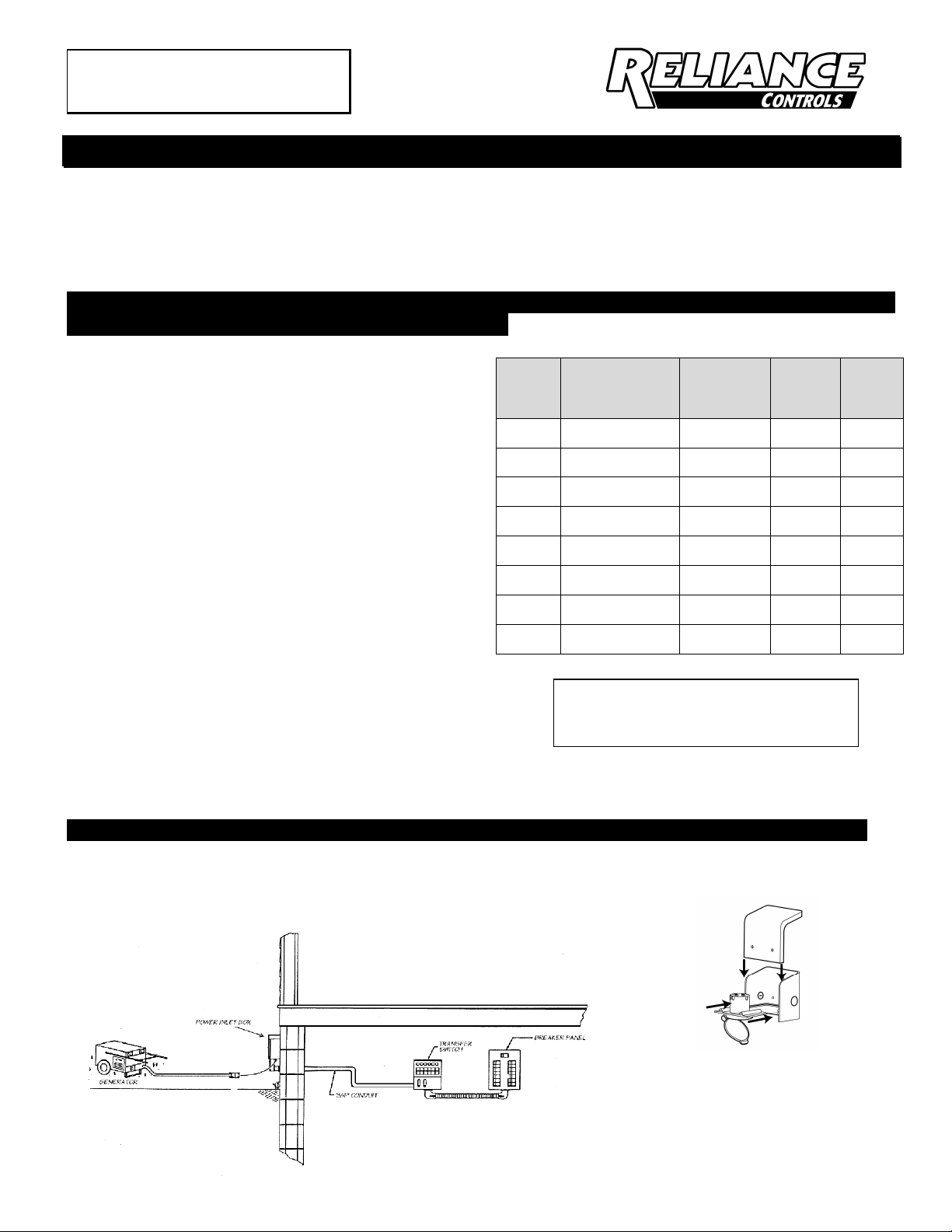
INSTALLATION D’UNE BOÎTE D’ENTRÉE ÉLECTRIQUE À DISTANCE POUR ALIMENTER LA PRISE
D’UN COMMUTATEUR OU PANNEAU DE TRANSFERT
Enlevez le couvercle de la boîte d'alimentation extérieure en dévissant
les deux vis à l'avant de la boîte avec un tournevis à #2 Phillips.
Glissez temporairement le plateau de câblage. Montez la plaque
arrière de la boîte d'alimentation à l'extérieur du bâtiment dans un
endroit commode, en utilisant les trois trous fournis. Enlevez l'un des
Knockouts réutilisables pop-Fast de la boîte en poussant à partir de
l'intérieur de la boîte d'entrée. Au moyen de fil de cuivre seulement
et des méthodes de câblage approuvées, passez les fils appropriés du
compartiment de filage du commutateur de transfert à travers le trou
enfoncé dans la boîte d’entrée électrique. Des raccords de 3/4 po
peuvent être installés directement dans le trou débouchant dans la
boîte d'alimentation. Pour utiliser des raccords de 1/2 po, insérez la
rondelle à Knockout en plastique (fournie dans la boîte d'alimentation)
dans le trou ouvert, puis installez le raccord. Les raccords doivent être
serrés à au plus 120 po-lb.
Dénuder l'isolant de fil 5/8 "et raccorder les fils aux orifices de câblage
situés à l'arrière de l'entrée d'alimentation dans le bac de la boîte
d'alimentation d'entrée de puissance comme suit pour s'assurer qu'il
n'y a pas d'isolant de fil dans n'importe quelle borne et les vis de borne
d'entrée sont serrées:
Les Fils chauds aux bornes en laiton marqués "X " et "Y ".
Fil neutre à la borne neutre nickelé marquée "W ".
Fil d'entrée de terre à la borne à vis verte marquée «G».
*Sur les entrées à 125 VCA seulement, les bornes seront identifiées
par les vis ; la vis de laiton est sous tension, la vis argent est neutre et
la vis verte est la mise à la terre.
Glissez le bac d'alimentation dans la boîte d'alimentation et insérez les
fils correctement. Replacez le couvercle du boîtier d'entrée à l'aide
des deux vis.
PRÉPARATION D'UN CORDON DU GÉNÉRATEUR À LA BOÎTE D'ENTRÉE DE PUISSANCE:
Au moyen d’un cordon de génératrice approprié pour cette utilisation, connectez la fiche mâle dans la prise génératrice
et le connecteur femelle dans l’entrée d’alimentation dans la boîte d’entrée électrique. Tournez pour verrouiller si la prise
est de type verrouillable.
Model
Number Amps/VAC
PBN15 15A 125VAC
PBN20 20A 125/250VAC
PBN21 20A 125VAC
PBN30 30A 125/250VAC
PBN31 30A 125VAC
PBN50 50A 125/250VAC
PBN51 50A 125VAC
PBN52 50A 125/250VAC
Ces boîtes d’entrées sont calibrées pour
être utilisées avec des fils dont l’isolant
est calibré à 60° C ou à 75° C.
Building
Wire Gauge
Min #14
Max #12 5-15R 5-15F
Min #12
Max #10 L14-20R L14-20F
Min #12
Max #10 L5-20R L5-20F
Min #10
Max #8 L14-30R L14-30F
Min #10
Max #8 L5-30R L5-30F
Min #8
Max #4
Min #8
Max #4
Min #8
Max #4
Gen
Outlet
14-50R
CS6369
CS6370 CS6377
14-50R 14-50F
PBN
Inlet
CS6375
RELIANCE CONTROLS
CORPORATION
2001 YOUNG COURT
RACINE, WI 53404
800-634-6155
 Loading...