

RELIANCE EASY/TRAN® TRANSFER SWITCH
MODEL NO: CSR-202
ELECTRICAL RATING: 20 Amps., 125/250 VAC, 50/60 Hz., 3-wire
5 KA SHORT CIRCUIT WITHSTAND TYPE 3 ENCLOSURE
SUITABLE FOR USE IN ACCORDANCE WITH ARTICLE 702 OF THE NATIONAL ELECTRICAL CODE, ANSI/NFPA 70.
THIS PRODUCT MEETS OR EXCEEDS ALL REQUIREMENTS OF UL1008 STANDARD FOR TRANSFER SWITCHES.
NON AUTOMATIC TRANSFER
SWITCH - 68UN
IMPORTANT: DISCONNECT ALL ELECTRICAL SUPPLY SOURCES BEFORE INSTALLATION AND
WIRING
WHEN SERVICING CONNECTED EQUIPMENT OR CIRCUITS.
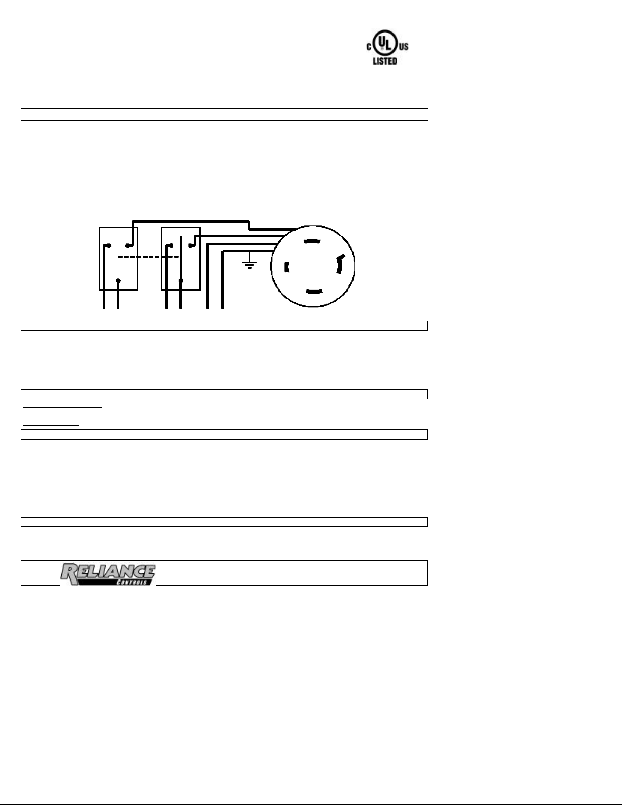
Remove the wiring compartment cove r by loosening the two screws that hold it in place, and lift out.
Six color-coded wire leads are provided. They are to be connected as follows:
RED (2): To incoming utility line, 250 VAC.
WHITE: To neutral.
BLACK (2): To load, 250 VAC
GREEN: To ground bar or terminal.
Replace wiring compartment cover when wiring is completed.
SWITCH 1 SWITCH 2
L14-20
POWER INLET
WHITE
RED
BLACK
RED
BLACK
USING THE RELIANCE TRANSFER SWITCH WITH A GENERATOR
THIS RELIANCE TRANSFER SWITCH IS NOT FOR "DO-IT-YOURSELF" INSTALLATION. Installer must be
thoroughly familiar with electrical wiring systems. This Reliance Transfer Switch is designed to provide, in the
event of a utility power outage, a safe and simple method of powering a single 250 volt circuit, or two 125 volt
circuits simultaneously, from a portable generator with a combination 125/250 VAC output. The DPDT selector
switch will feed the circuit load(s) from either the utility or the generator, and prevent backfeeding of one source
from another.
KEY COMPONENTS OF THE TRANSFER SWITCH
SELECTOR SWITCH. Selects either "LINE" (utility) or "GEN" (generator) as the source feeding the circuit
load(s).
POWER INLET. NEMA L14-20 configuration. Inputs power from the portable generator.
TRANSFERRING FROM UTILITY POWER TO GENERATOR POWER
1. Move the selector switch handle to the "OFF" or “LINE” position.
2. Insert the male power cord plug into the appropriate outlet on the generator. If locking receptacle is used,
rotate to lock.
3. Insert the female power cord connector into the power inlet located on the lower face of the transfer switch.
Rotate to lock.
4. Start the generator, following the procedures described in the generator owner's manual furnished by the
generator manufacturer.
5. Move the selector switch knob to the "GEN" position to energize load from generator.
TRANSFER RING FROM GENERATOR POWER BACK TO UTILITY POWER
1. Move the selector switch handle to the "LINE" position to energize load from utility.
2. Follow the procedures in the generator owner's manual to turn off the generator.
3. Disconnect the power cord.
GREEN
RELIANCE CONTROLS CORPORATION
2001 Young Court Racine, WI 53404
FORM OPCSR302 101502
I:\Reliance\MOF Reliance\Labels\LoadSide\CSR202 Oper Inst rev3.doc
 Loading...