

Reliance Controls 3006HDK User Manual
ELECTRICAL INNOVATION SINCE 1909
™
TT RR AA NN SS FF EE RR EE QQ UU II PP MM EE NN TT FF OO RR PP OO RR TT AA BB LL EE GG EE NN EE RR AA TT OO RR SS
II NN SS TT AA LL LL AA TT II OO NN AA NN DD
OO PP EE RR AA TT II NN GG
II NN SS TT RR UU CC TT II OO NN SS
For Power Transfer Kit Model
3006 HDK
TABLE OF CONTENTS
Page
Tools Needed for Installation 1
Parts List 1
Safety Symbols Used in this Manual 1
About Generators and Transfer Switches 2
Key Product Components 3
Pre-Planning the Load on Your Generator 4
Load Balancing Examples 5
Installation Instructions
Mounting the Transfer Switch 6
Connecting the Flexible Conduit 6
Grounding the Transfer Switch 7
Installing 120 Volt Circuits 7
Installing 240 Volt Circuits 8
Completing the Installation 8
Installing and Wiring the Power Inlet Box 9
Wiring the Power Inlet Box to the Transfer Switch 9
Installing an Optional Power Inlet 10
Finishing Up 10
Operating Instructions 10
Product Specifications 11
Page 1
TOOLS NEEDED FOR INSTALLATION
1. Power Drill
2. Wire Stripper and Cutter (10 to 14 gauge)
3. Insulated Screwdrivers
(#2 Phillips, 1/4" Flat Tip or #2 Square Tip depending on
your load center)
4. Hammer
5. Marking Pencil
6. Tape Measure
7. Seven Wall Anchors with at Least a 3/8” Flange
8. Enough 10-3 with Ground Building Wire to reach from
where you install your Outdoor Power Inlet Box to where
you install your transfer switch
9. Battery Powered Lighting during Installation
10. A Non-Contact Voltage Detector (optional)
PARTS LIST for 31406CRK POWER TRANSFER KIT
SAFETY SYMBOLS USED IN THIS MANUAL
Danger indicates an imminently hazardous
situation that, if not avoided, could result in
death or serious injury.
Warning indicates a potentially hazardous
situation that, if not avoided, could result in
death or serious injury.
Caution indicates a potentially hazardous
situation that, if not avoided, may result in
minor or moderate injury.
Reliance transfer switches covered
in this manual should not be used for
electric water heaters, clothes dryers, electric ranges,
central air conditioners or other appliances or systems
that may exceed the capacity of the product.
Improper installation of the transfer
switch could cause damage or
personal injury by electrocution or fire. Installation must be
performed by a qualified electrician, or others
knowledgeable of electrical systems, in compliance with
all applicable electrical codes.
DANGER
WARNING
CAUTION
WARNING
WARNING
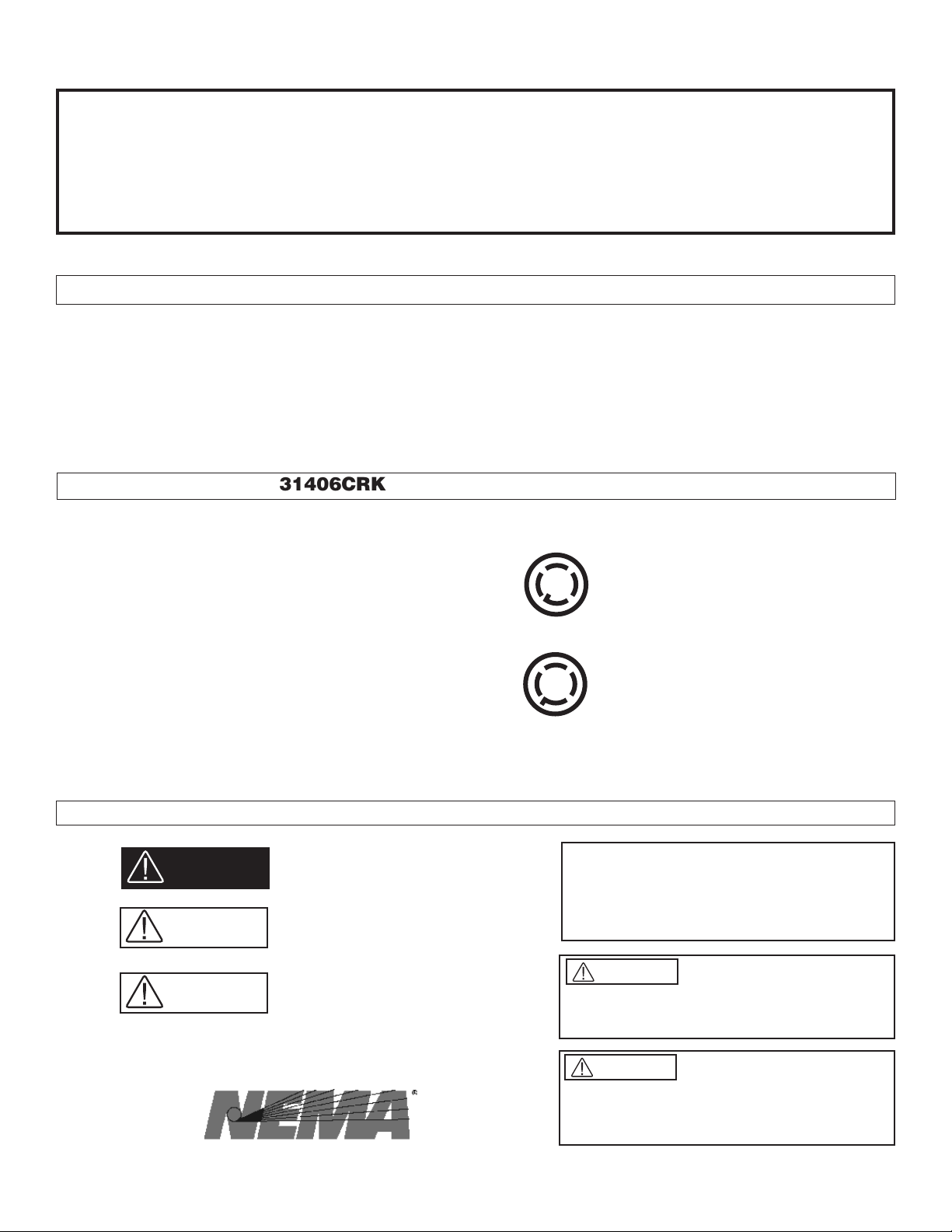
NOTE: The 30 Amp power cord plugs into this type of
generator power outlet:
If your generator only has a 20 Amp power outlet like this:
install the 20 Amp Power Cord Plug on your power cord
according to its included instructions.
3006 HDK
Reliance Controls Corporation is not responsible for
damage or injury caused by incorrect installation of
this transfer switch.
When the transfer switch is
connected to branch circuits with AFCI or GFCI breakers,
the AFCI or GFCI protection will be lost when, and only
when, the toggle switch is in the GEN position. To get
AFCI or GFCI protection when running on generator
power, it must be provided at the outlet(s).
The double pole branch circuits
connected to this transfer switch are considered live unless
both switches controlling the circuit are in the off position. The
position of the transfer switch circuit breakers are not to be
relied upon to disconnect the circuit.
WARNING
WARNING
Congratulations on your purchase of the Reliance Controls generator power transfer switch. Reliance has been
manufacturing transfer switches and equipment in Racine, Wisconsin since 1983 and has been producing high-quality
electrical equipment for nearly 100 years. Reliance is the Loadside® transfer switch used in nearly 90% of the installations
done by professional electricians.Your transfer switch is UL 1008 listed, C-UL listed, and meets all requirements of the
National Electrical Code.
7KLVtransfer switch LV made to operate with any generator having20 or 30 Amp twist-lock power receptacles.
30 Amp 6-Circuit Transfer switch
30 Amp Outdoor Power Inlet Box
30 Amp 10-foot long Generator Power Cord
20 Amp Interchangeable Power Cord Plug
4 red and 6 yellow wire connectors
Installation and Operating Instructions'9'
Tr ansfer switches are required for use with portable generators by Article
702 of the National Electrical Code
Member of the National Electrical Manufacturers Association
Page 2
ABOUT GENERATORS AND TRANSFER SWITCHES
Generators and transfer switches are dependent on one another as a system to power your home in a power out
situation. The Reliance Controls transfer switch system is needed because 1) your portable generator is very powerful and
the power it creates must be safely controlled to protect you and your electric utility provider, and 2) even with all of its power,
your generator probably cannot power all of the electrical circuits and devices in your home without help from a transfer
switch with load management capabilities.
The Reliance Controls transfer switch is designed to let you control and distribute your generator’s power. It correctly
distributes the power from your portable generator to your home circuitry through your electrical load center. It also
eliminates the need for messy cords running to your electrical appliances through open doors and windows. The Reliance
Controls transfer switch working with your generator takes the worry and inconvenience from power outage situations.
The Reliance Controls transfer switch distributes the power from your generator through its toggle switches to the
corresponding selected branch circuits that power the major appliances you choose to operate during a power outage (such
as your sump pump, refrigerator or furnace). However, because each of these branch circuits may power several other
electrical devices other than your major appliances, such as the items plugged into wall sockets and permanently installed
lighting, we recommend that you do a little pre-planning by:
1. Picking the key electrical appliances you want to power in an emergency
2. Finding the essential circuit breakers that control these devices
3. Creating a map of all of the other electrical devices plugged into or wired into these circuits
A tear-off Home Circuit Mapping Chart on the back of this manual should be completed and posted next to your transfer
switch to help you in managing the load on your generator. Make sure you note on the chart which electrical devices you will
not need during a power outage so that these can be turned off prior to starting your generator.
During a power outage, you can run your generator and transfer switch system in two ways:
• You can set up your transfer switch to run all of its circuits at the same time once you flip the toggles to the GEN position.
Setting your system up in this way will be discussed in the “Balancing the Load” section later.
• You can also use the load management function of the Reliance Controls transfer switch that allows you to alternate the
devices you choose to run at any given time. If your generator is running at or near its maximum output, selected circuits
can be switched off and others can be switched on for brief periods of time. For example, you can run a microwave oven
for a brief period from the transfer toggle switch that controls your microwave circuit, if you first turn off the transfer switch
toggle switch that controls your furnace—for that same brief period.
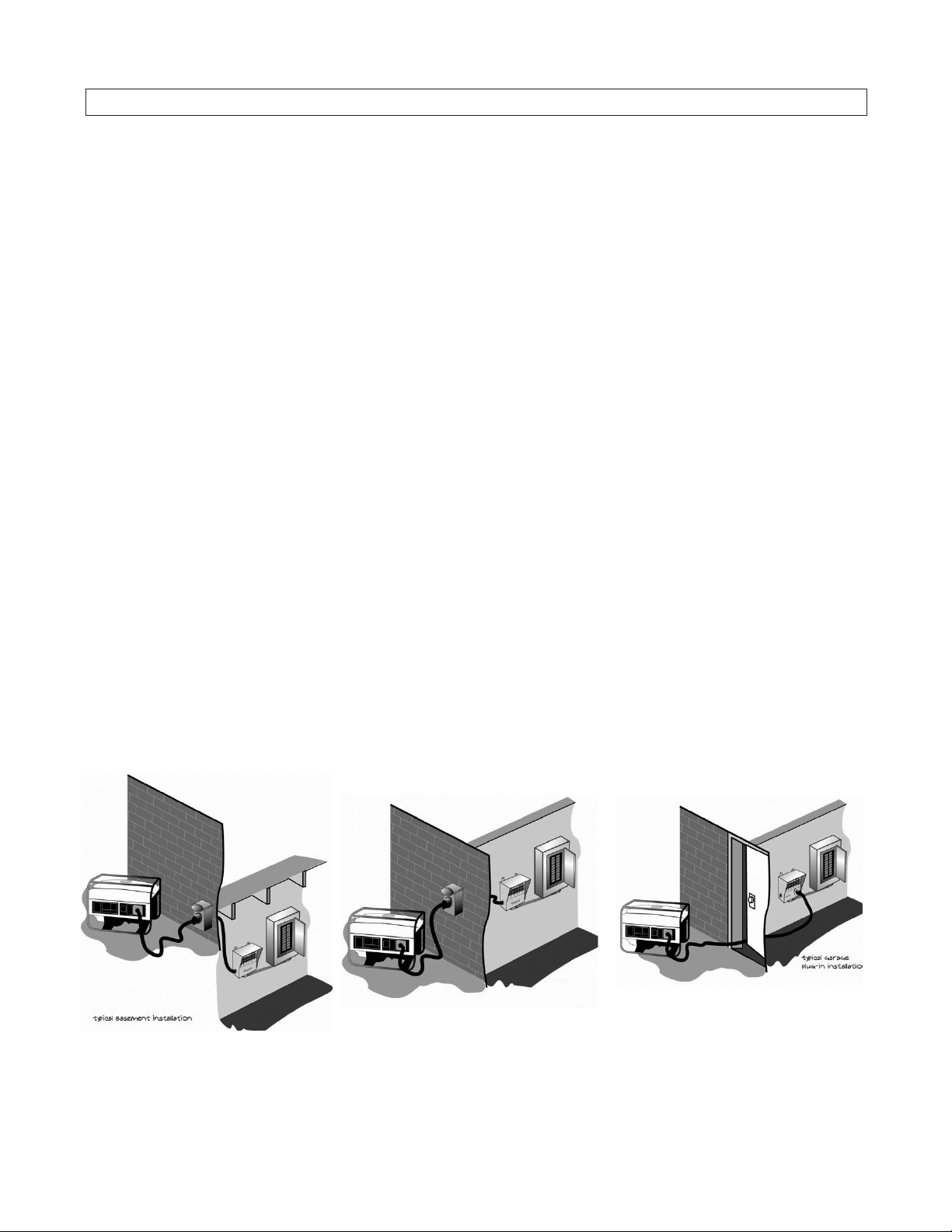
Typical Generator and Transfer Switch Installations
Generator Plugged into Outdoor Power Inlet
Box Wired to Transfer Switch Next to
Basement Load Center
(POSSIBLE KIT INSTALLATION)
Generator Plugged into Interchangeable
Power Inlet on Transfer Switch with
20-foot Cord
(POSSIBLE INSTALLATION WITH
AVAILABLE RELIANCE ACCESSORIES)
Generator Plugged into Outdoor Power Inlet
Box Wired to Transfer Switch Next to Garage
Load Center
(POSSIBLE KIT INSTALLATION)
Page 3
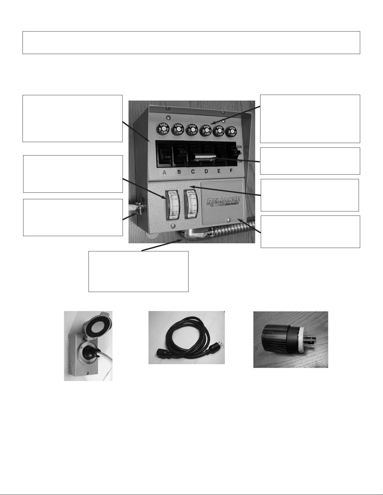
KEY COMPONENTS OF THE RELIANCE CONTROLS TRANSFER SWITCH AND
POWER TRANSFER KIT
Circuit Selector Toggle Switches
These switches allow you to select either GEN
(generator) or LINE (utility) as the power source
for the branch circuits that have been wired
through the transfer switch. The OFF position
generally is not used, as a switch in the OFF
position removes that circuit both from generator
and utility power.
Wattmeters
Wattmeters indicate the total load on your
generator measured in watts resulting from the
appliances that are running using generator
power. They are calibrated to show how close
your generator is to its capacity.
Knockout Holes
Located on both sides, the bottom and the back of
your transfer switch, these knockouts are easily
removed with a screwdriver and a hammer and
allow the direct wiring of your transfer switch with
building wire.
Branch-Rated Circuit Breakers
Each transfer switch circuit controlled by a toggle
switch has a built-in corresponding 15 or 20 Amp
push-to rest circuit breaker that protects the
branch circuit when the toggle switch is in the
GEN position. In the LINE position, each branch
circuit is protected by the breaker in the load
center.
Handle Ties
Used to link two 120 Volt circuits together to
create a 240 volt circuit to run larger appliances
such as a well pump.
Wiring Compartment Front Plate
Removing the two screws which attach this plate,
reveals the internal wiring compartment. Inside
are four pre-stripped wires which connect to the
incoming generator-powered wires.
Power Inlet Hole Cover Plate
This logo plate removes with one screw to allow
the insertion of an accessory power inlet on the
front of your transfer switch to allow direct
connection to the generator with a power cord.
Pre-Wired Flexible Conduit Whip
Contains all of the hot, neutral and ground wires
required to make connections between your
transfer switch and the circuit breakers in your
load center you choose to control. Each wire is
color-coded and marked with the switch letter for
easy identification.
30 Amp Outdoor Power Inlet Box
30 Amp NEMA 3-configured outdoor
generator Power inlet Box mounts to the
outside of your house near to where your
generator will be running. It allows direct
wiring to your transfer switch and load
center from a remote location.
30 Amp Twist-Lock Power Cord
30 Amp 10-foot long outdoor-rated
power cord has L14-30 connectors.
One end plugs into your generator
power outlet and the other into the
Reliance Power Inlet Box.
20 Amp Interchangeable
Power Cord Plug
Allows the use of the Reliance 30
Amp power cord on smaller
generators with only 20 Amp power
outlets, by replacing the 30 Amp plug
on the cord supplied.
Your Reliance Controls transfer switch is unique in two ways: 1) it has a patented internal wiring compartment which eliminates the need
for the installation of additional junction boxes, and 2) it has a removable front panel which allows a power inlet to be easily inserted to
allow a power cord to be plugged directly into the transfer switch with a longer power cord. Although this is not the installation addressed by
the 3+'. Kit, such an installation may be desirable depending on your situation.
Page 4
PRE-INSTALLATION PLANNING OF THE GENERATOR LOAD
Before you begin installing your Reliance Controls transfer switch system, you need to create a plan for the appliances you choose
to run during a power outage. To do this, it’s helpful to first know how your generator produces power. If your generator has four-prong
twist-lock 20 or 30 Amp output receptacles, and is set-up for home stand-by operation, it likely will produce 120/240 Volt power, or power
similar to your electrical utility. This type of power generation is useful as it: 1) allows common 120 Volt circuits, such as lights or small
appliances, to be operated, and 2) allows two 120 Volt circuits to be linked together to operate a 240 Volt device, such as a well pump.
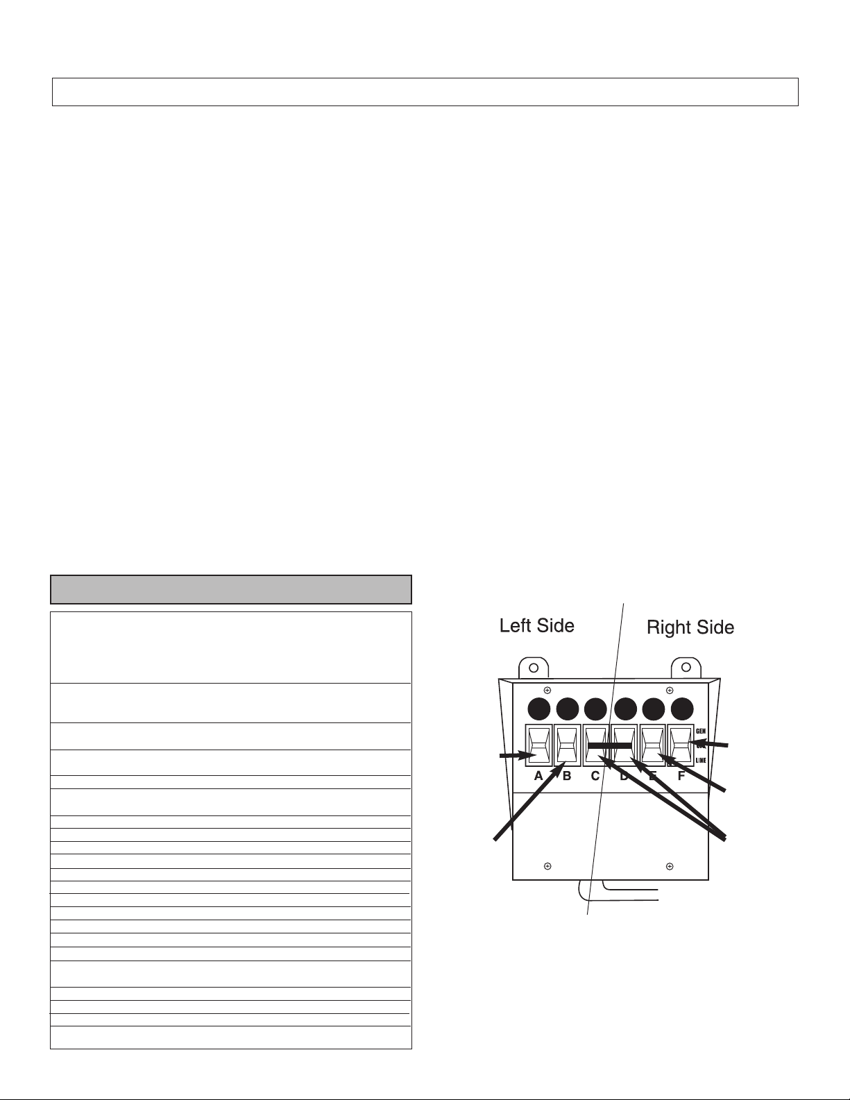
Because of the way in which larger portable generators are designed, they generate power in two equal halves. A generator which
has output of 5000 continuous running watts, for example, generates power from two 2500 watt “sides”. In setting up a transfer switch
to get the most power from your generator, it is desirable to “balance the load” between the two halves of your transfer switch, or the left
side and the right side. Devices which will consume the most of the generator’s wattage should be divided between the two sides. Load
balancing is shown in Figure 1. For example, on the 6-circuit transfer switch shown in Figure 1, consider wiring the breaker controlling
the refrigerator to toggle switch A, the furnace breaker to toggle switch B, the sump pump breaker to switch E and the breaker controlling
your TV and VCR to toggle switch F. You may want to reserve switches C and D to be linked with a handle tie and wired to a double pole
breaker controlling, for example, a 240 Volt well pump.
The Residential Wattage Requirements Table below shows sample wattages used by typical household appliances and can help
you plan the set up of your transfer switch. Use the running watts of your appliances rather than starting watts when dividing them
between the two halves of the transfer switch. Check your appliances for actual wattage requirements if possible.
Your Reliance Controls transfer switch also allows you to manage the load on your generator manually by switching appliances
on and off as you need them, so the capacity of either half of your generator is not exceeded. However, if you prefer not to manage your
transfer switch loads manually, leave a buffer equal to the largest start-up wattage requirement of all of the appliances you are going to
run continually when doing your calculation. This buffer, along with the peak wattage of your generator, will allow for the periodic motor
start-up of any one large appliance, such as your refrigerator. If your transfer switch is equipped with watt meters, you can visually
monitor the amount of wattage being used by the appliances your generator is powering at any time.
Examples of load balancing calculations are shown on the worksheets on page 5. Use these to create your own plan.
TYPICAL RESIDENTIAL WATTAGE REQUIREMENTS
Additional
Running Start-Up
Appliance Wattage Wattage
Furnace (1/3 HP) 700 1,400
Furnace (1/2 HP) 875 2,100
Window Air Conditioner
6000 BTU 1,200 2,100
12,000 BTU 1,700 2,900
Well Pump (1/3 HP) 750 1,400
Well Pump (1/2 HP) 1,000 2,350
Sump Pump (1/3 HP) 800 1,300
Sump Pump (1/2 HP) 1,050 2,150
Refrigerator 800 2,300
Garage Door Opener (1/4 HP) 550 1,100
Garage Door Opener (1/3 HP) 750 1,400
Home Security System 200 0
Lights On Bulb On Bulb
Stereo 200 0
TV/VCR 200 0
Computer 200 0
Microwave Check oven Check Oven
Coffee Maker 1,750 0
Toaster 1,300 0
Electric Fan 200 0
Clothes Washer 1,150 2,300
Clothes Dryer (Gas) 700 1,800
Dishwasher (Cool Dry) 700 1,400
Dishwasher (Hot Dry) 1,450 1,400
Vacuum Cleaner 1,000 0
Hair Dryer Check Dryer Check Dryer
Iron 1,200 0
Circular Saw 800 2,000
Figure 1
Refrigerator
(800 Watts)
Furnace
(875 Watts)
Well Pump
(1000 Watts)
Sump Pump
(1,050 Watts)
TV / VCR
(200 Watts)
 Loading...