

Page 1
OPERAOPERA
OPERA
OPERAOPERA
TORS’ GUIDETORS’ GUIDE
TORS’ GUIDE
TORS’ GUIDETORS’ GUIDE
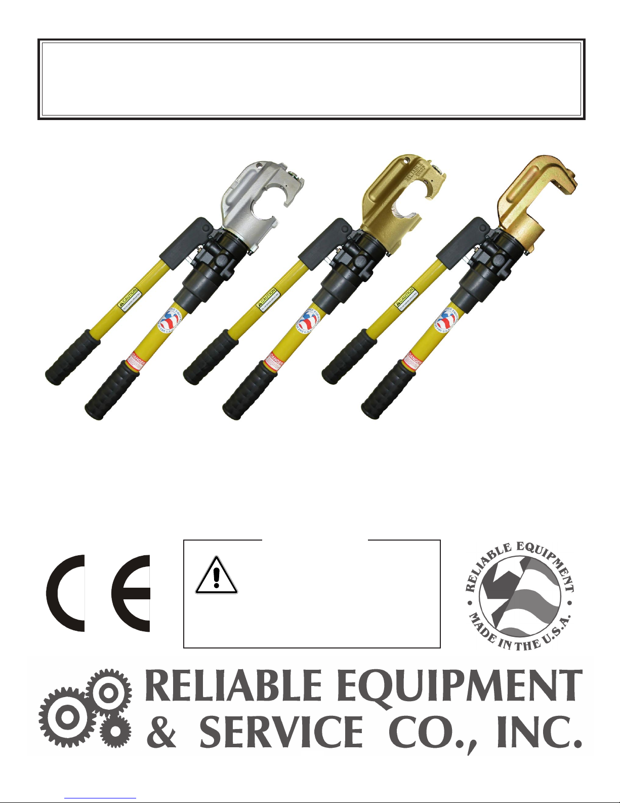
REL-430 REL-510 REL-510K
REL-430, REL-510, & REL-510K
HAND OPERATED HYDRAULIC CRIMPING TOOLS
WARNINGWARNING
WARNING
WARNINGWARNING
All information found in this guide
must be read and understood before
use or testing of this tool.
Failure to read and understand these warnings
and safe handling instructions could result
in severe personal injury and or death.
DISTRIBUTED BDISTRIBUTED B
DISTRIBUTED B
DISTRIBUTED BDISTRIBUTED B
YY
Y
YY
MAN. HYD. CRIMPING Manual 09-14
1
Page 2

DISTRIBUTED BDISTRIBUTED B
DISTRIBUTED B
DISTRIBUTED BDISTRIBUTED B
YY
Y
YY
REGISTRATION
UPON RECEIPT OF THIS TOOL, COMPLETE THE REGISTRATION BELOW.
COMPANY ___________________________________________________________
ADDRESS ____________________________________________________________
______________________________________________________________________
PHONE ______________________ FAX __________________________________
SERIAL NUMBER ____________________________________________________
DATE OF PURCHASE ________________________________________________
DEALER NAME _______________________________________________________
The information in this manual is intended to guide the user in
the use and application of this tool. It is not intended as a
substitute for proper training and experience in safe work
CAUTION
practices for this type of equipment.
Consult your supervisor or safety personnel if you have any
questions regarding the safe operation of this tool.
2
Page 3

TABLE OF CONTENTS
DISTRIBUTOR INFORMATION .............................................................2
TABLE OF CONTENTS ............................................................................3
REGISTRATION .......................................................................................3
TOOL SPECIFICATIONS
REL-430 ...............................................................................................4
REL-510 ...............................................................................................5
REL-510K.............................................................................................6
SAFETY INFORMATION AND WARNINGS ..................................... 7-8
DAILY MAINTENANCE ............................................................................9
OPERATING INSTRUCTIONS ...............................................................9
MAN. HYD. CRIMPING HANDLE PARTS LIST ..............................10-11
FIXED HANDLE PART DRAWING #1 .......................................... 12
MOVABLE HANDLE PART DRAWING #2................................... 1 3
NOTE: FIXED HANDLE DWG #1 AND MOVABLE HANDLE DWG #2
PART #S WILL REMAIN CONSTANT FOR ALL MODELS, REFER
TO HANDLE PARTS LIST ON PAGES 10 AND 11 FOR THESE ITEMS.
REL-510
REL-510 HEAD DRAWING #3 ...................................................... 1 4
REL-430 HEAD PARTS LIST ......................................................... 15
REL-430
REL-430 HEAD DRAWING #4 ...................................................... 1 6
REL-430 HEAD PARTS LIST ......................................................... 17
REL-510K
REL-510K HEAD DRAWING #5.................................................... 1 8
REL-510K HEAD PARTS LIST ....................................................... 19
LABELS................................................................................................... 20
MAINTENANCE RECORDS................................................................. 22
CONTACT INFORMATION................................................................... 2 2
THIS SYMBOL INDICATES ITEMS OF EXTREME IMPORTANCE.
Safety of user and others may be in jeopardy if these instructions
are not read and understood.
3
Page 4
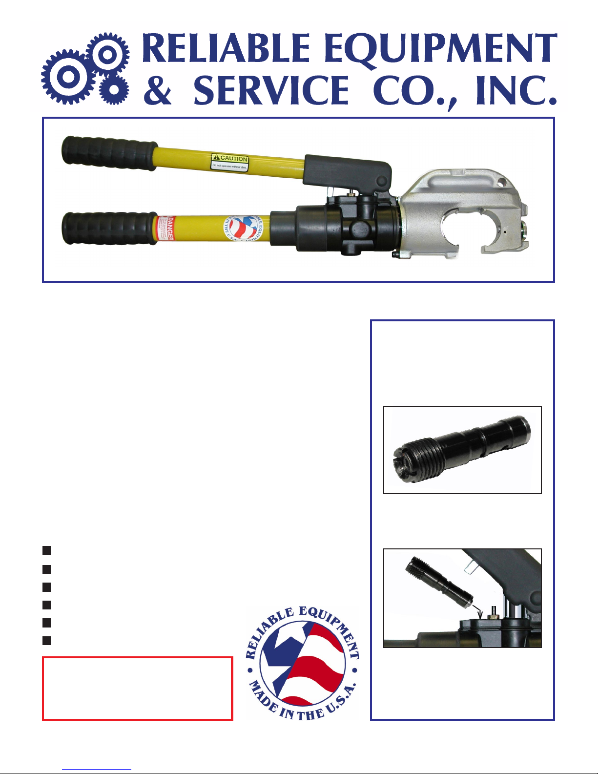
REL-430
REL-430
Weight: 13.5 lbs., Length: 24 inches
REL-430 MANUAL HYDRAULIC 12 TON CRIMPING TOOL
Designed to crimp splices to 600 MCM and lugs to
750 MCM. The REL-430 Accepts standard Reliable
R12 (12 ton) “U” style dies as well as many dies
from Alcoa, Burndy, Blackburn, Thomas & Betts,
and Huskie. The 1-3/16" jaw opening allows use
on larger cable diameters and connectors than
standard 1" opening tools. The 180
O
swivel head
permits use in confined areas. Replaceable drop
out by-pass cartridge facilitates shop repairs.
Two-stage pumping piston for rapid advance,
and twist handle release. Magnetic oil reservoir
plug traps metal contaminants.
FEATURES:
Crimping Head rotates 180
O
´ Replaceable drop-out bypass cartridge
´ Accepts all existing R12 “U” Style dies
´ Two stage pumping piston
Reliable Equipment’s line of
manual hydraulic compression
tools offer a unique bypass
system, featuring an adjustable,
replaceable bypass cartridge.
Bypass Cartridge
This unit can be easily replaced
or externally calibrated without
dismantling the tool.
´ Twist handle release
´ Carrying case included
Connector Range:Connector Range:
Connector Range:
Connector Range:Connector Range:
Lugs Up to 750 MCM
Splices Up to 600 MCM
This tool can be recalibrated in
the field, using a hex wrench to
adjust desired pressure, without
removing the tool from service.
4
Page 5
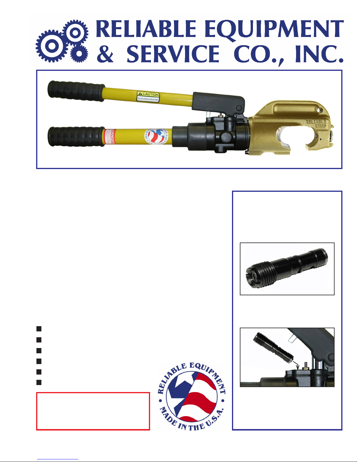
REL-510
REL-510
Weight: 14.5 lbs., Length: 25 inches
REL-510 MANUAL HYDRAULIC 12 TON CRIMPING TOOL
Designed to crimp splices to 750 MCM and lugs
to 750 MCM Al & Cu. The REL-510 Accepts
standard Reliable R12 (12 ton) “U” style dies as
well as many dies from Alcoa, Burndy, Blackburn,
Thomas & Betts, and Huskie. The 1-1/2" jaw
opening allows use on larger cable diameters and
connectors than standard 1" opening tools. The
O
180
swivel head permits use in confined areas.
Reliable Equipment’s line of
manual hydraulic compression
tools offer a unique bypass
system, featuring an adjustable,
replaceable bypass cartridge.
Replaceable drop out by-pass cartridge facilitates
shop repairs. Two-stage pumping piston for rapid
advance, and twist handle release. Magnetic oil
reservoir plug traps metal contaminants.
FEATURES:
Crimping Head rotates 180
O
´ Replaceable drop-out bypass cartridge
´ Accepts all existing R12 “U” Style dies
´ Two stage pumping piston
´ Twist handle release
´ Carrying case included
CONNECTCONNECT
CONNECT
CONNECTCONNECT
Lugs Up to 750 MCM
Splices Up to 750 MCM
OR RANGE:OR RANGE:
OR RANGE:
OR RANGE:OR RANGE:
Bypass Cartridge
This unit can be easily replaced
or externally calibrated without
dismantling the tool.
This tool can be recalibrated in
the field, using a hex wrench to
adjust desired pressure, without
removing the tool from service.
5
Page 6
REL-510K
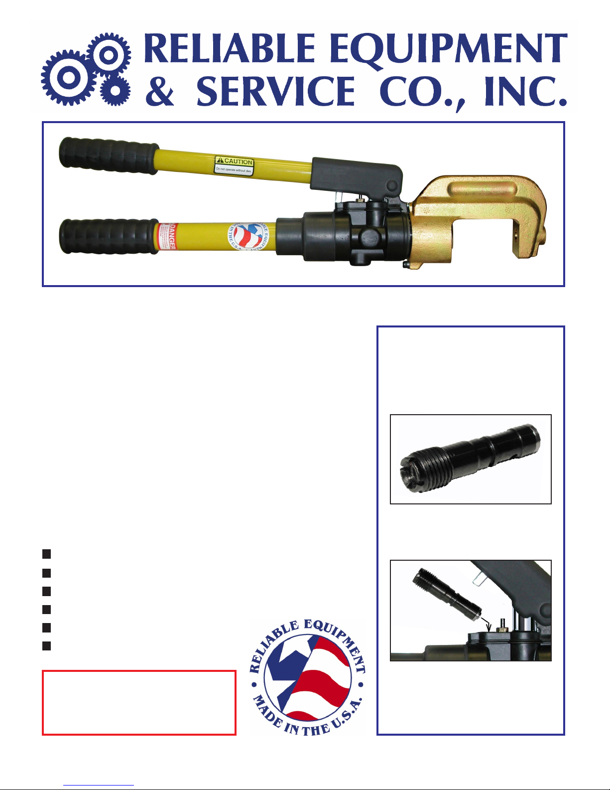
REL-510K
Weight: 17 lbs., Length: 26 inches
REL-510K MANUAL HYDRAULIC 12 TON CRIMPING TOOL
Designed to crimp splices to 477ACSR and lugs to
1033 MCM. The REL-510K accepts standard
Kearney style dies. The 1-1/2 inch jaw opening
allows use on larger cable diameters and
connectors than standard 1" opening tools.
Additional features include: 180
O
swivel head which
permits use in confined areas. The replaceable drop
out by-pass cartridge facilitates shop repairs.
Two-stage pumping piston for rapid advance,
and twist handle release. Magnetic oil reservoir
plug traps metal contaminants.
FEATURES:
Crimping Head rotates 180
O
´ Replaceable drop-out bypass cartridge
´ Accepts all existing R12 “U” Style dies
´ Two stage pumping piston
Reliable Equipment’s line of
manual hydraulic compression
tools offer a unique bypass
system, featuring an adjustable,
replaceable bypass cartridge.
Bypass Cartridge
This unit can be easily replaced
or externally calibrated without
dismantling the tool.
´ Twist handle release
´ Carrying case included
Connector Range:Connector Range:
Connector Range:
Connector Range:Connector Range:
Lugs Up to 477 ACSR
Splices Up to 1033 MCM
This tool can be recalibrated in
the field, using a hex wrench to
adjust desired pressure, without
removing the tool from service.
6
Page 7
BEFORE USING THIS TOOL, READ THE WARNINGS
and the recommended practices described in this manual.
Failure by the operator to read and fully understand these
warnings will leave this person unqualified to use and
operate this tool. Property damage, severe personal injury,
WARNING
These warnings will appear in appropriate locations when they are pertinent to the
particular subject being shown. Read each one carefully and follow them strictly .
and/or death could result by not following these warnings.
Eye
Protection
WARNING
Always wear eye protection to avoid
injury from flying debris or hydraulic
oil leaks. Failure to do so can result
in serious personal injury.
Hard Hat
WARNING
Always wear a hard hat to avoid injury
from falling debris. Failure to do so
can result in serious personal injury.
Dust Mask
WARNING
Always wear a dust mask. Failure to
observe this warning may result
in serious health issues and/or
breathing difficulty.
Foot
Protection
WARNING
Always wear foot protection.
Failure to do so can result in serious
personal injury.
Hearing
Protection
WARNING
Always wear hearing protection,
to avoid hearing loss due to long
term exposure to high noise levels.
Protective
Gloves
WARNING
Always wear protective gloves
Failure to do so can result in serious
personal injury.
7
Page 8
WARNING
WARNING
Operation/Safety methods may vary in accordance
with the working guidelines established by each utility
or contractor.
For your own safety, ensure that you fully comply with
all safe operation guidelines required by your employer.
ELECTRICAL SHOCK HAZARD
Always wear and use the necessary clothing, equipment and
safety practices to protect against electrical shock. Failure to
follow these rules can result in serious personal injury or death.
GENERAL SAFETYGENERAL SAFETY
GENERAL SAFETY
GENERAL SAFETYGENERAL SAFETY
USE ALL APPROPRIATE AND APPLICABLE PERSONAL SAFETY EQUIPMENT
as required by the operating company.
ALWAYS INSPECT TOOL for wear or deterioration every day.
Replace all parts that show signs of wear or damage.
INSPECT TOOL BEFORE USE. Replace any worn, damaged or missing parts.
A damaged or improperly assembled tool may injure operator and/or nearby personnel.
KEEP ALL PARTS OF THE BODY AWAY from moving parts of the tool.
KEEP HANDS OUT FROM BETWEEN CRIMPING JAWS AT TOOL HEAD.
ALL BODY PARTS SHOULD BE OUTSIDE DANGER ZONE PRIOR TO CRIMPING.
MAKE SURE there is no person in close proximity to you or the tool who could be
injured by any operation being performed, tool malfunction or flying debris.
DO NOT OVEREXTEND your position by overreaching or unbalancing the footing
necessary to maintain physical control of your body and the tool.
ALWAYS MAINTAIN a firm grip on the tool to avoid loss of control during an operation,
causing property damage, serious injury or death.
USE THIS TOOL FOR THE MANUFACTURERS’ INTENDED PURPOSE ONLY.
OBSERVE CLOSELY ALL SAFETY RULES FOR A PARTICULAR JOB CLASS
FAILURE TO HEED THESE WARNINGS COULD RESULT IN
PROPERTY DAMAGE, SERIOUS PERSONAL INJURY OR DEATH.
8
Page 9

DAILY MAINTENANCE
The life, reliability, and safety of the tool is dependent on proper maintenance.
Clean all surfaces including head, die seat, ram, and handles.
Inspect for wear and damage. Worn or damaged parts may malfunction during operation.
All parts must be replaced with new parts if signs of wear or damage are evident.
Keep Label Set clean and legible. Replace decals when necessary.
OPERA OPERA
OPERA
OPERA OPERA
Read entire manual prior to using this tool.
(Refer to all safety recommendations and warnings)
Observe all safety precautions and procedures required by the operating company.
Also refer to SAFETY information found on pages 7 and 8 )
Before crimping, ensure that crimp is within the capacity listed for the tool.
Ensure that you are using the proper die, as recommended by the connector manufacturer.
Insert proper die into die seat using die buttons. NEVER OPERATE WITHOUT DIES.
Place tool over connector.
Advance ram to connector with fast advance feature on handle.
Align jaw as necessary to ensure proper crimp.
NOTE: Jaw may be released as needed at any point in the crimp cycle.
Continue pumping until relief valve “pops” off. Action will become very easy.
Crimp is complete.
TIONTION
TION
TIONTION
To release ram from connector, open pump handle completely.
Rotate pump handle (movable) 45
This will release the ram & retract from connector.
Repeat steps above as necessary.
Manufacturer recommends regular testing for proper pressure and operation.
Test at least every 6 months, test more often under heavy usage.
IF YOU HAVE ANY QUESTIONS REGARDING THE PROPER USE
AND/OR OPERATION OF THIS TOOL, CONSULT YOUR AREA SUPERVISOR,
OR CONT ACT RELIABLE EQUIPMENT AT 800-966-3530
O
& hold while closing completely.
9
Page 10
MAN. HYD. CRIMPING HANDLE PARTS LIST
ITEM QT Y PART NO DESCRIPTION DRAWING #
1 1 R19101 BODY, MACHINED 2
7 1 R18007 RETURN SPRING 2
8 1 R18008 CAP, SPRING 2
9 1 R18009 SNAP RING, CAP STOP 2
10 1 R19010 REAR STOP 1
12 2 R18012 HARD BALL, 7/32 DIA. 1, 2
13 2 * R18013 O’RING 1, 2
14 2 * R18014 BU RING 1, 2
15 1 R18015 RELEASE PLUNGER 2
16 1 R18016 SPRING, RELEASE 1
17 1 R18017 BRASS NUT 2
18 1 R18018 SIDE PLUG 2
19 1 R18019 PINTLE, SIDE PLUG 2
20 1 R18020 CHECK CAP 1
21 1 R18021 BALL, 3/16, FEED CHK. 1
22 1 R18022 FILTER BODY 1
23 1 R18023 SCREEN, BRASS 1
24 1 R18024 FINGER CLIP 1
25 1 R18025 MOUNT, BODY HANDLE 1
26 1 R18026 RESERVOIR PLUG ASSY, R410-55 1
27 1 R18027 MAGNET, ASSY R410-55 1
28 1 R18028 HANDLE, FIBERGLASS BODY, 430-10HT 1
29 1 R18029 PUMP ARM, FIBERGLASS, 410-30 2
30 1 R18030 SHOULDER HOUSING 2
31 1 R18031 POINTER
32 1 R18032 RELEASE FINGER 2
33 4 R18033 BRONZE BUSHINGS 2
34 1 R18034 KNUCKLE 2
35 1 R18035 FAST ADV. PLUG 1
2
36 1 R18036 SET SCREW, 6-32 X 3/16 2
37 1 R18037 3/32 BALL 2
38 1 R18038 LOWER CHK. SPRG. 1
39 2 R18039 UPPER CHK SPRG. 1
40 1 R28540 PISTON INJECTOR 2
10
Page 11

MAN. HYD. CRIMPING HANDLE PARTS LIST
ITEM QTY PART NO DESCRIPTION DWG #
41 1 *R28541 WIPER 2
42 1 *R18042 O’RING, LO PR PISTON 2
43 1 *R18043 O’RING, HI PRESS PISTON 2
48 1 R18048 BALL, 1/4 1
49 1 R18049 PIVOT PIN, SHOULDER 2
50 1 R18050 TORSION SPRING 2
51 2 R18051 9/32 BALL 1
54 1 R19054 GRIP, PUMP ARM, R410-31
55 1 R19055 GRIP, HANDLE, R510-31 1
56 2 R18056 SNAP RINGS, C31 2
57 2 R18057 3/16 X 1 3/8 ROLL PIN 2
60 1 R18200 PRESET PRES . RELIEF 2
61
63 2 R18077 SPRING 1, 2
66 1 *R13821 O’ RING 1, 2
68 1 R18080 SPRING 2
75 1 R410-57 COVER, HANDLE HEAD, R410-57 2
80 1 *R18013 O’RING, SIDE PLUG 2
82 1 R13082 10-32 X 3/8 SHCS 2
83 1 *R18058 O’RING 1, 2
84 1 *R18059 O’RING 2
89 1 REL510-A-31 RUBBER COVER, BODY 1
1 R430-09 RESERVOIR 1
2
90 1 R510-31 RUBBER MOUNT COVER 1
SEAL KIT INCLUDES PARTS MARKED *
Complete disassembly is not recommended. Return the unit to an authorized dealer
for total disassembly and/or repair.
All maintenance or disassembly should take place on a flat, clean work surface
cov e r e d with towels or wipers so as to have a clean space for the disassembled parts.
Inspect each part during disassembly for wear, scratches, and cuts. Discard the worn
or damaged parts and replace with new factory authorized parts.
O-rings are sensitive to sharp edges. Inspect closely for cuts or damage. A small cut
will cause a leak. When assembling or disassembling O-rings, use hydraulic fluid
as a lubricant to help disassembly or installation.
11
Page 12
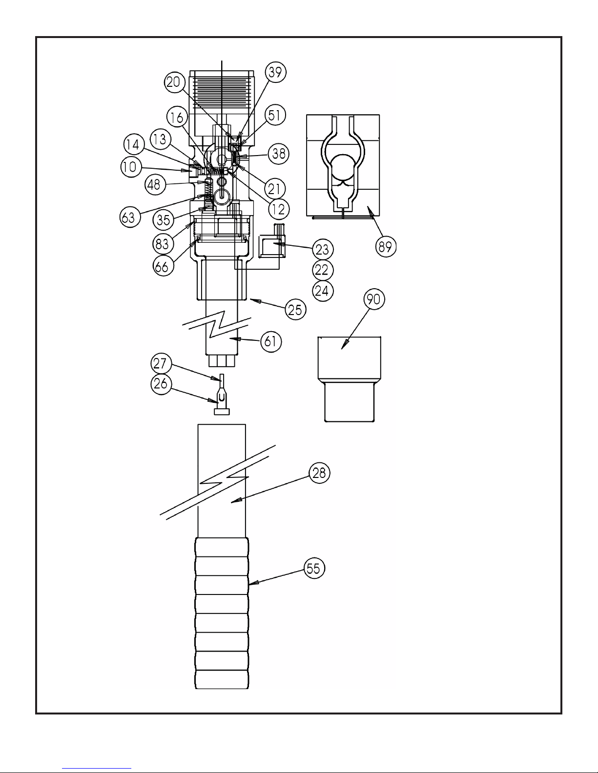
FIXED HANDLE DWG #1
PARTS DRAWING
SEE PAGE #10-11
12
Page 13
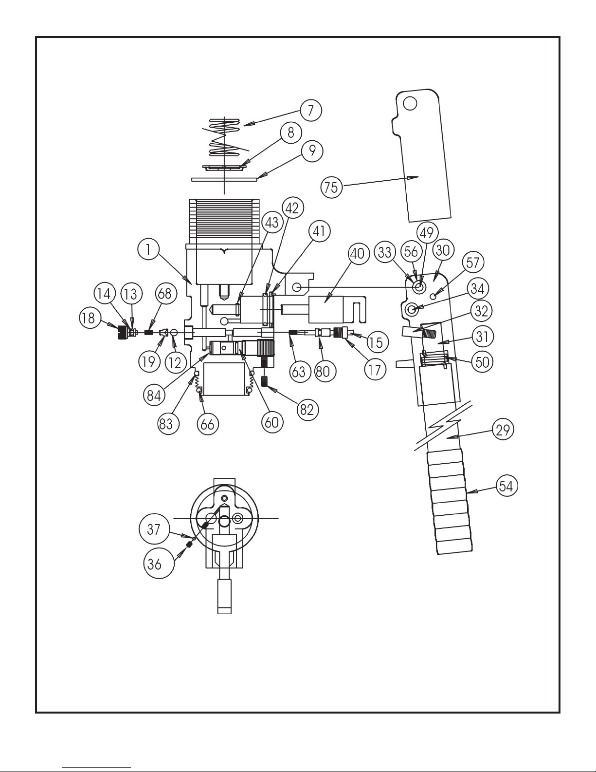
MOVABLE HANDLE
DWG #2
PARTS DRAWING
SEE PAGE #10-11
13
Page 14
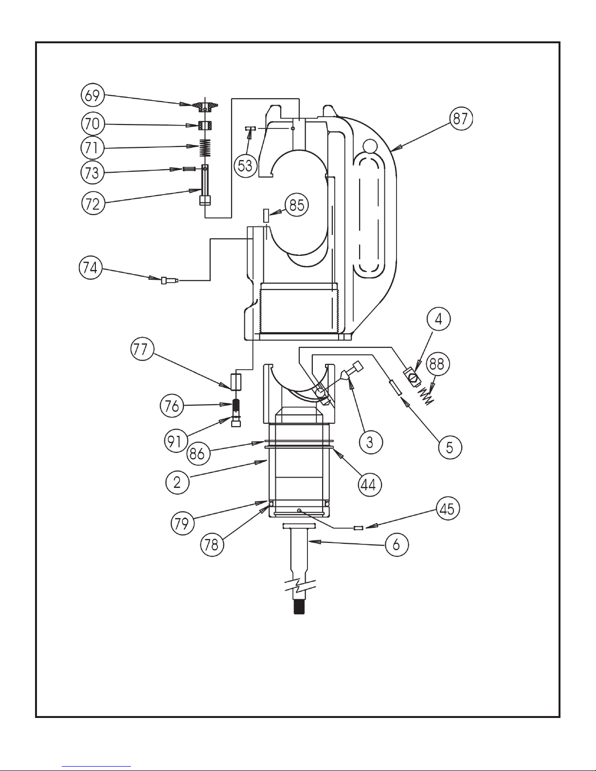
DWG #3
REL-510 HEAD
PARTS DRAWING
SEE PAGE #10-11
14
Page 15
REL-510 HEAD PARTS LIST
ITEM QTY PART NO DESCRIPTION DRAWING #
2 1 R19002 RAM 3
3 1 R18003 DIE BUTTON
4 1 R18004 DIE PIN 3
5 1 R19005 SPRING PIN, 3/32 X 1/2 3
6 1 R18007 CENTER POST 3
44 1 * R19044 WIPER 3
45 1 R18045 PIN, 3/32 X 1/4, FOR RAM 3
53 1 R19053 PIN, 2.4 X 24MM 3
69 1 R19149 KNOB, 1220-20 D
70 1 R19051 SCREW W/THRU HOLE, 1220-3 3
71 1 R19052 SPRING, 1220-4 3
72 1 R19058 DIE RETAINING PIN 3
73 1 R19059 DRIVE PIN, 1220-16
74 1 R19020 5 X 10MM SHCS, 1220-15 3
76 2 R19076 5 X 15MM SHCS 3
77 2 R19077 FERRULE 3
78 1 * R13820 O’RING 3
3
3
3
79 1 * R13821 BU RING 3
85 1 R19085 RAM ROTATION KEY 3
86 1 R19086 WASHER, WIPER BACK UP 3
87
88
91 2 R18091 LOCK WASHER FOR 5 MM SHCS 3
SEAL KIT INCLUDES PARTS MARKED *
1 R28502 HEAD 3
1 R13020 SPRING 3
Complete disassembly is not recommended. Return the unit to an authorized
dealer for total disassembly and/or repair.
All maintenance or disassembly should take place on a flat, clean work surface
cov e re d with towels or wipers so as to have a clean space for the disassembled parts.
Inspect each part during disassembly for wear, scratches, and cuts. Discard the worn
or damaged parts and replace with new factory authorized parts.
O-rings are sensitive to sharp edges. Inspect closely for cuts or damage. A small cut
will cause a leak. When assembling or disassembling O-rings, use hydraulic fluid
as a lubricant to help disassembly or installation.
15
Page 16
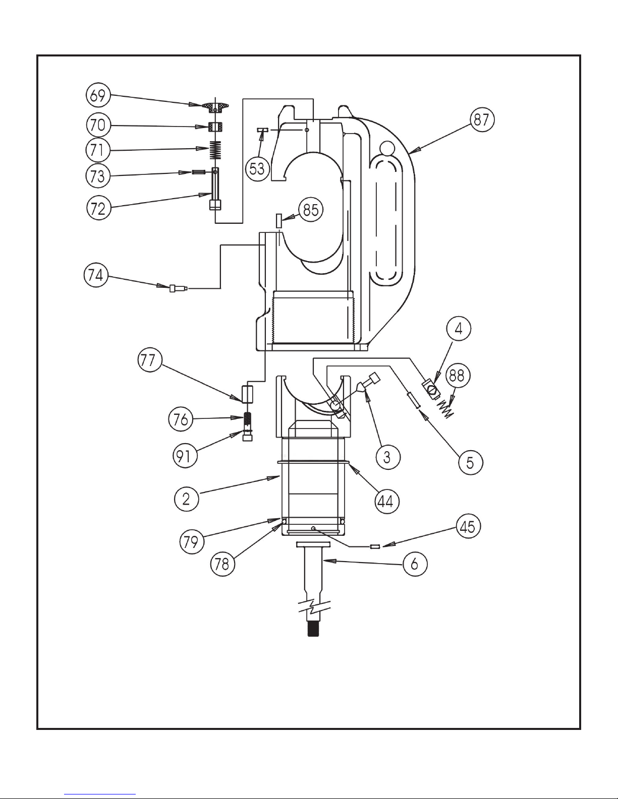
DWG #4
REL-430 HEAD
PARTS DRAWING
16
Page 17
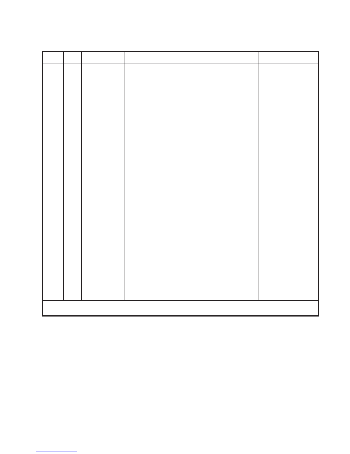
REL-430 HEAD PARTS LIST
ITEM QTY PART NO DESCRIPTION DRAWING #
2 1 R19002 RAM 4
3 1 R19013 DIE BUTTON
4 1 R18004 DIE PIN 4
5 1 R18005 SPRING PIN, 3/32 X 1/2 4
6 1 R18007 CENTER POST 4
44 1 * R19044 WIPER 4
45 1 R18045 PIN, 3/32 X 1/4, FOR RAM 4
53 1 R19053 PIN, 2.4 X 24MM 4
69 1 R1220-20D KNOB, 1220-20 D
70 1 R1220-3 SCREW W/THRU HOLE, 1220-3 4
71 1 R1220-4 SPRING, 1220-4 4
72 1 R1220-5 DIE RETAINING PIN 4
73 1 R1220-16 DRIVE PIN, 1220-16 4
74 1 R1220-7 5 X 10MM SHCS, 1220-15 4
76 2 R19076 5 X 15MM SHCS 4
78 1 * R13820 O’RING 4
79 1 * R13821 BU RING 4
4
4
85 1 R1220-15 RAM ROTATION KEY 4
87
88
91 2 R18091 LOCK WASHER FOR 5 MM SHCS 4
SEAL KIT INCLUDES PARTS MARKED *
1 REL-430-01 HEAD 4
1 R12817 SPRING 4
Complete disassembly is not recommended. Return the unit to an authorized dealer
for total disassembly and/or repair.
All maintenance or disassembly should take place on a flat, clean work surface
cov e re d with towels or wipers so as to have a clean space for the disassembled parts.
Inspect each part during disassembly for wear, scratches, and cuts. Discard the worn
or damaged parts and replace with new factory authorized parts.
O-rings are sensitive to sharp edges. Inspect closely for cuts or damage. A small cut
will cause a leak. When assembling or disassembling O-rings, use hydraulic fluid
as a lubricant to help disassembly or installation.
17
Page 18
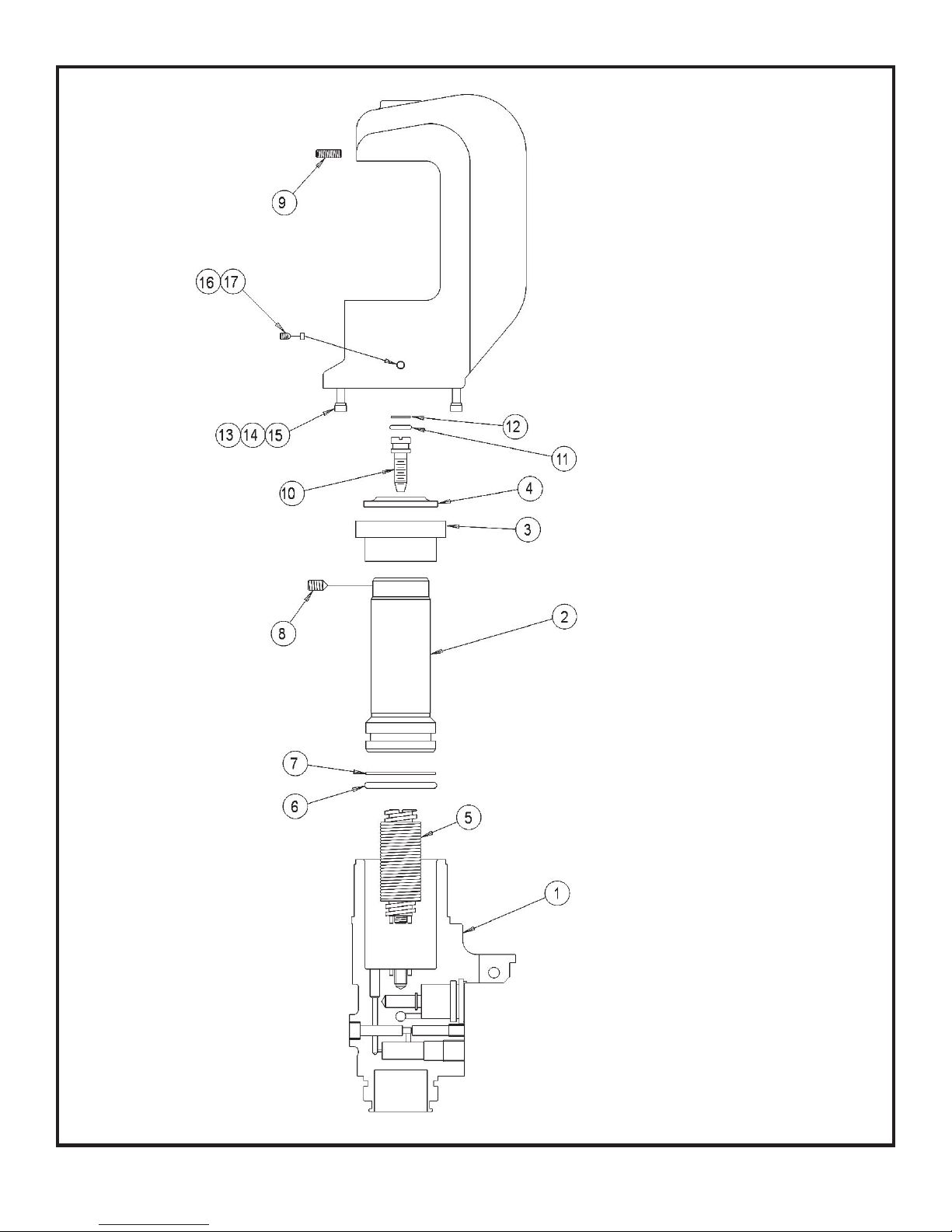
REL-510K DWG #5
PARTS DRAWING
18
Page 19
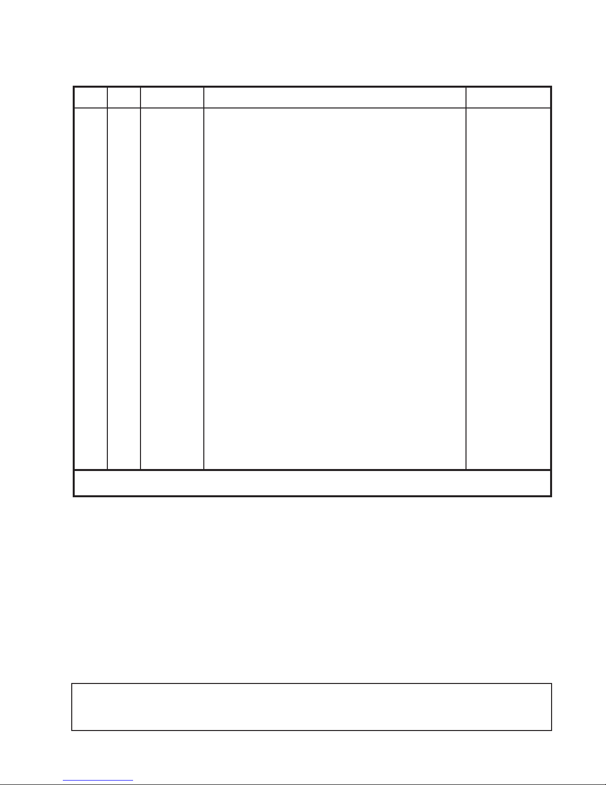
REL-510K PARTS LIST
ITEM QTY PART NO DESCRIPTION DRAWING #
1 1 28001 510 BODY 5
2 1 28002 RAM 5
3 1 28003 COLLAR 5
4 1 28004 *WIPER, SER-40 5
5 1 28005K RETURN SPRING ASSY 5
6 1 13820 *O-RING 5
7 1 13821 *B/U RING 5
8 2 28021 CONE POINT SOCKET SET SCREW, 1/4-20 X 3/8 5
9 1 28016 SOCKET SET SCREW, 6 X 16 MM, CONE POINT 5
10 1 28010 BOLT, SPRING SEAL 5
11 1 28011 *O-RING, SEAL BOLT, 012UR70 5
12 1 28012 *B/U RING, SEAL BOLT, 012STBU 5
13 2 28022 SCREW, 5 X 20 MM SHCS 5
14 2 18091 LOCKWASHER 5
15 2 28024 SPACER 5
16 1 28025 5 X 5 MM SOCKET SET SCREW 5
17 1 28026 PLASTIC INSERT 5
18 1 28300 SEAL KIT 5
SEAL KIT INCLUDES PARTS MARKED *
Complete disassembly is not recommended. Return the unit to an authorized dealer
for total disassembly and/or repair.
All maintenance or disassembly should take place on a flat, clean work surface
cov e r e d with towels or wipers so as to have a clean space for the disassembled parts.
Inspect each part during disassembly for wear, scratches, and cuts. Discard the worn
or damaged parts and replace with new factory authorized parts.
O-rings are sensitive to sharp edges. Inspect closely for cuts or damage. A small cut
will cause a leak. When assembling or disassembling O-rings, use hydraulic fluid
as a lubricant to help disassembly or installation.
IF YOU HAVE QUESTIONS REGARDING THE REPAIR AND MAINTENANCE OF
THIS TOOL CONTACT RELIABLE EQUIPMENT AT 800-966-3530
19
Page 20
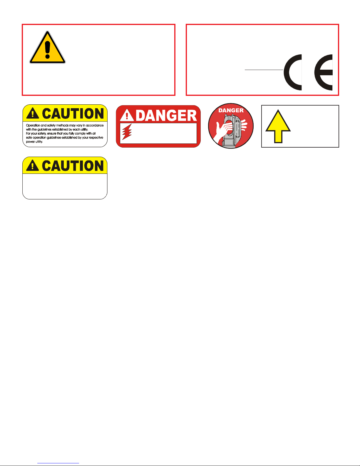
BEFORE USING THIS PRODUCT
READ THE SAFETY WARNINGS
and recommended practices described
in the manual. Failure by the operator to
read and fully understand the warnings
will leave this person unqualified to use
WARNING
Failure to observe all warnings and instructions could result
in property damage, severe personal injury, and/or death.
and operate the tool.
REL-SM
The user should be properly
trained in the correct procedures
required for work on or aroun d
ELECTROCUTION
electrical lines.
HAZARD
Do not operate without dies.
REL-SM
RELIABLE EQUIPMENT & SERVICE CO., INC.
92 Steamwhistle Drive • Ivyland, PA 18974 • USA
Phone: 215-357-3500 • Fax: 215-357-9193
MODEL: _____________
MAX. PRESSURE:
___________
SERIAL NO.: ____________
YEAR: ___________
DD
ANGERANGER
D
ANGER
DD
ANGERANGER
RAM
CLOSES
NOTE: Keep Label Set clean and legible. Replace decals when necessary. Part #RL19400
20
Page 21

21
Page 22
Maintenance Records
Date Parts or Service Required
If you have any questions regarding the information
found in this manual please contact RELIABLE EQUIPMENT at the
address, phone or fax numbers shown below.
301 Ivyland Road Warminster, PA 18974
Phone: 800-966-3530 Fax: 215-357-9193
Visit us on the web at www.Reliable-Equip.com
22
 Loading...