

Reliable Controls SS-L-BL-CO2-H20, SS-CO2-UD, SS-CO2-H-UD, SS-CO2-OC-UD, SS-H-O-S User Manual
...
better by design
™
SMART-Sensor
User Guide
™

better by design
™
™
SMART-Sensor
User Guide
© 2002 - 2014 Reliable Controls® Corporation. All rights reserved.

DOCUMENT CONVENTIONS
This document features several conventions to help you learn the material and
procedures. These conventions are outlined below.
Bold-faced type for Window Title Bars.
e.g., The Inputs worksheet is open.
Initial capitals for Field Names and Buttons.
e.g., The value of the Panel Program field is pan. Click the Save button.
Italics in lowercase for field values, file types, directories, and file paths.
e.g., The value of the Panel Program field is pan.
SMART-SENSOR
™
DOCUMENT CONVENTIONS
The pan files are stored in the pan subdirectory of the job directory.
Italics in initial uppercase for Mode Types.
e.g., Toggle the Mode button to switch to Update mode.
Chevrons denote menu items.
e.g., To exit, select Access > Bye from the main menu.
All uppercase for KEYWORDS and Control-BASIC STATEMENTS.
e.g., Click ALARMS to open the Current Alarms worksheet.
Underscore connectors for section references.
e.g., Refer to Reference_Alarms_Alarm Configuration more details.
2004 – 2014 Reliable Controls® Corporation. All rights reserved.
USER GUIDE
i

The following symbols are used to draw your attention to important information.
The exclamation symbol is used to highlight material that requires caution or thought
before implementation.
The light bulb symbol is used to highlight helpful information and practices.
2002 – 2014 Reliable Controls
®
Corporation. All rights reserved.
Printed in Canada
This manual is for information purposes only. The contents and products described are
®
subject to change without notice. Reliable Controls
with respect to this manual. In no event shall Reliable Controls
Corporation makes no representation
®
Corporation be liable for
damages, direct or incidental, arising out of or related to the use of this manual. No part of
this document may be reproduced or transmitted in any form or by any means, without the
®
express written permission of Reliable Controls
Corporation.
Reliable Controls Corporation Tel: 250-475-2036
120 Hallowell Road Fax: 250-475-2096
Victoria, BC, Canada, V9A 7K2 Toll Free: 1-877-475-9301
www.reliablecontrols.com
Reliable Controls, RC-Studio®, and the Reliable Controls logo are registered trademarks of Reliable Controls Corporation.
®
BACnet
is a registered trademark of ASHRAE.
MACH-ProCom, MACH-ProSys, MACH-System, MACH-Global, MACH1, MACH2, MACH-Air, MACH-Zone, MACH-ProAir, MACHProZone, MACH-Pro1, MACH-Pro2, MACH-Stat, SMART-Sensor, SMART-Space, MODBUS-Link, RC-Archive, RC-Toolkit, MACHProWeb, SMART-Space EnOcean Accesspoint, SPACE-Sensor EnOcean, RC-Studio, RC-Reporter, and RC-WebView are trademarks of Reliable Controls.
ii
10/01/14 JW
2004 – 2014 Reliable Controls® Corporation. All rights reserved.

SMART-SENSOR
TABLE OF CONTENTS
OVERVIEW ......................................................................................................................................... 01
GETTING STARTED .......................................................................................................................... 03
ACKAGE CONTENTS ............................................................................................................... 03
P
P
HYSICAL LAYOUT ................................................................................................................... 04
SS-L M
SS M
SS-P M
SS-DUCT M
P
HYSICAL DIMENSIONS ............................................................................................................ 08
SS
SS-P M
SS-DUCT-PB M
SS-DUCT-GD M
M
ODELS .................................................................................................................................. 14
B
O
ODELS ..................................................................................................................04
ODELS .....................................................................................................................05
ODELS .................................................................................................................06
ODELS ..........................................................................................................07
AND SS-L MODELS .....................................................................................................08
ODELS .................................................................................................................11
ODELS ....................................................................................................12
ODELS ...................................................................................................13
ASE MODELS .................................................................................................................14
RDERING OPTIONS .........................................................................................................18
™
TABLE OF CONTENTS
SMART-NET NETWORK TOPOLOGY ............................................................................................... 22
ENSORS PER CONTROLLER ..................................................................................................... 22
S
M
AXIMUM CABLE LENGTHS ...................................................................................................... 23
SMART-S
ENSOR EXPANSION BOARD (SSX) ............................................................................ 24
ORTS .....................................................................................................................25
SSX P
OWER ............................................................................................................................25
P
ND OF LINE (EOL) TERMINATION ....................................................................................26
E
ET TERMINATION ............................................................................................................27
N
NSTALLING ONE SSX EXPANSION BOARD .........................................................................28
I
NSTALLING MULTIPLE SSX EXPANSION BOARDS ................................................................30
I
INSTALLATION .................................................................................................................................. 32
AND SS-L MODELS ............................................................................................................ 32
SS
OOLS .............................................................................................................................32
T
NSTALLATION PROCEDURE ...............................................................................................33
I
SS-DUCT M
SS-P M
W
IRING DETAILS ...................................................................................................................... 41
ODELS .............................................................................................................. 38
ODELS ...................................................................................................................... 39
VERVIEW .......................................................................................................................41
O
IRING FROM CONTROLLER TO SS ...................................................................................42
W
IRING BETWEEN SMART-SENSORS ................................................................................44
W
USER GUIDE
2004 – 2014 Reliable Controls® Corporation. All rights reserved.
iii

CONFIGURING THE SS .................................................................................................................... 46
A
DDRESSING THE SS ............................................................................................................... 46
A
DDRESSING THE SS-L ............................................................................................................ 47
S
ECONDARY POINT DISPLAY .................................................................................................... 48
OPERATOR INTERFACE .................................................................................................................. 49
PERATOR INTERFACE FOR THE SS .......................................................................................... 49
O
ETPOINT ADJUSTMENT OPTIONS ......................................................................................49
S
EST LED ........................................................................................................................49
T
VERRIDE BUTTON ...........................................................................................................50
O
O
PERATOR INTERFACE FOR THE SS-L ...................................................................................... 51
CREEN INTERFACE ..................................................................................................52
LCD S
EGREE C/F SWITCH .......................................................................................................53
D
ISPLAY MODES ...............................................................................................................54
D
ECONDARY POINT ...........................................................................................................54
S
UICK-ADJUST MODE ......................................................................................................55
Q
ISPLAY POINT MODE ......................................................................................................55
D
ACKLIGHT FOR THE SS-L ................................................................................................56
B
SOFTWARE PROGRAMMING .......................................................................................................... 57
CCESSING THE SS WORKSHEET ............................................................................................. 57
A
T
HE SS WORKSHEET ............................................................................................................... 60
ALUES DISPLAYED ..........................................................................................................60
V
ESERVED POINTS ...........................................................................................................61
R
OLUMNS ........................................................................................................................62
C
OMMAND BAR ................................................................................................................64
C
SMART-S
ENSOR SETUP DIALOG BOX ...............................................................................64
INPUT/OUTPUT POINT OPTION (-IO) .............................................................................................. 66
NPUTS .................................................................................................................................... 66
I
O
UTPUTS ................................................................................................................................. 67
CARBON DIOXIDE SENSOR OPTION (-CO2) ................................................................................. 70
VERVIEW ...............................................................................................................................70
O
B
ACKPLATE ............................................................................................................................. 71
W
IRING ................................................................................................................................... 72
C
ALIBRATION ........................................................................................................................... 72
UTOMATIC ......................................................................................................................72
A
ANUAL ..........................................................................................................................73
M
C
ONFIGURATION ..................................................................................................................... 75
OCCUPANCY SENSOR OPTION (-OC) ............................................................................................ 76
DUCT OPTION (-DUCT) .................................................................................................................... 78
NETWORK COMMUNICATION JACK .............................................................................................. 79
ONNECTING AN X-PORT-2 CONVERTER ................................................................................... 80
C
ONBOARD CONFIGURATION TOOLS (SS-L) ................................................................................. 81
iv
2004 – 2014 Reliable Controls® Corporation. All rights reserved.

SMART-SENSOR
SS-L ADDRESS TOOL .............................................................................................................. 82
S
ETUP TOOL ............................................................................................................................ 83
F
LOW TOOL ............................................................................................................................. 87
D
ISABLE SS-L CONFIGURATION TOOLS .................................................................................... 91
PROGRAMMING AND CONFIGURATION EXAMPLES .................................................................... 92
ROGRAMMING EXAMPLE ................................................................................................... 92
SS P
SS-L P
SPECIFICATIONS ............................................................................................................................. 112
P
D
N
C
A
P
O
O
O
O
A
A
ROGRAMMING EXAMPLE ................................................................................................ 100
OWER ................................................................................................................................. 112
ISPLAY (SS-L ONLY) ........................................................................................................... 112
ETWORK .............................................................................................................................112
OMMISSIONING/PROGRAMMING ........................................................................................... 112
MBIENT LIMITS ................................................................................................................... 113
HYSICAL ............................................................................................................................. 113
NBOARD TEMPERATURE SENSOR ........................................................................................ 114
NBOARD HUMIDITY SENSOR (OPTIONAL) ................................................................................ 114
ODELS WITH -H OPTION ...........................................................................................114
SS M
SS-DUCT-EH-RH M
NBOARD MOTION SENSOR (OPTIONAL, -OC MODELS ONLY) ................................................ 115
NBOARD CARBON DIOXIDE SENSOR (OPTIONAL, -CO2 MODELS ONLY) ................................ 115
UXILIARY INPUTS (OPTIONAL, -IO MODELS ONLY) ................................................................ 115
UXILIARY OUTPUTS (OPTIONAL, -IO MODELS ONLY) ................................................................ 116
ODELS WITH -IO OPTION ..........................................................................................116
SS M
SS-DUCT M
ODELS WITH -IO OPTION ...............................................................................116
ODEL ...............................................................................................114
™
2004 – 2014 Reliable Controls® Corporation. All rights reserved.
USER GUIDE
v

NOTES
vi
2004 – 2014 Reliable Controls® Corporation. All rights reserved.

SMART-SENSOR
SS-L-D/W
SS-P
SS-DUCT-PB
SS-DUCT-GD
SS-UD
OVERVIEW
The Reliable Controls® SMART-Sensor™ (SS) is a powerful and dynamic microprocessor-based sensor
that monitors room environmental conditions, and communicates the information back to
MACH-System controllers via SMART-Net™. SMART-Sensor™ LCD (SS-L) models also include the ability
to display and adjust setpoints and other control points located in MACH-System controllers.
™
OVERVIEW
FIGURE 1: SMART-SENSOR™ SS-UD, SS-L-D/W, SS-P, SS-DUCT-PB, AND SS-DUCT-GD
SS FEATURES INCLUDE:
•
Network up to 16 SMART-Sensors on a single SMART-Net
on the host controller type,
• Fully compatible with all generations of MACH-System controllers,
• Optional LCD display, humidity, CO
, occupancy, 2 Input/2 Output, degree C/F
2
switch, override button, and setpoint slider.
•
(SS-L) Display up to ten points from any Reliable Controls
controller, located anywhere in the system,
•
• (SS-L) Access, view, and adjust data easily with the three-button interface and
(SS-L) Adjust up to ten points from the SMART-Net
®
Reliable Controls
large three-row LCD display,
MACH-System controller,
™
network depending
®
MACH-System
™
host, which can be any
USER GUIDE
2004 – 2014 Reliable Controls® Corporation. All rights reserved.
1

• (SS-P) Measure room temperature in locations where the sensor could be
subject to damage.
• (SS-DUCT) Measure duct temperature and humidity.
2
2004 – 2014 Reliable Controls® Corporation. All rights reserved.

GETTING STARTED
P
ACKAGE CONTENTS
SMART-SENSOR PACKAGE CONTENTS
SMART-SENSOR
Package Contents
™
GETTING STARTED
•
• (SS, SS-L)Two 6–32 1" Phillips screws
• (SS-DUCT) 2 x 1" #8 hex slotted sheet metal screws
• (SS-P) 2 x 1" 6-32 slotted device box screws
One SMART-Sensor
wiring box (SS-DUCT)
™
with backplate (SS, SS-L) or SS coverplate (SS-P) or
2004 – 2014 Reliable Controls® Corporation. All rights reserved.
USER GUIDE
3

PHYSICAL LAYOUT
Backplate
Sensor head
LCD screen (optional)
Optional occupancy sensor
Three-button keypad
X-Po rt-2
™
access port
Two 1 . 6 mm (
1
/16”) Allen screws
(secure sensor head to backplate)
Cooling vents
Sensor head
X-Po rt-2
™
converter access port
Optional Degrees C/F switch
SS-L MODELS
4
FIGURE 2: PHYSICAL LAYOUT (SS-L-OC, SS-L-D PICTURED)
2004 – 2014 Reliable Controls® Corporation. All rights reserved.

SS MODELS
Optional Setpoint Buttons (SS-CO2-UD)
Optional Slider (SS-S)
Thicker backplate for -CO2 models
Two 1.6 mm (
1
/16”) Allen screws
(secure sensor head to backplate)
X-Po rt -2™ converter access port
SMART-SENSOR
Physical Layout
™
GETTING STARTED
FIGURE 3: PHYSICAL LAYOUT (SS-CO2-UD AND SS-S PICTURED)
2004 – 2014 Reliable Controls® Corporation. All rights reserved.
USER GUIDE
5

SS-P MODELS
SS-Plate (SS-P) SS-Plate with Override (SS-P-O)
FIGURE 4: PHYSICAL LAYOUT (SS-P AND SS-P-O PICTURED)
6
2004 – 2014 Reliable Controls® Corporation. All rights reserved.

SS-DUCT MODELS
SS-DUCT-PB SS-DUCT-GD
SMART-SENSOR
Physical Layout
™
GETTING STARTED
FIGURE 5: PHYSICAL LAYOUT (SS-DUCT-PB AND SS-DUCT-GD PICTURED)
2004 – 2014 Reliable Controls® Corporation. All rights reserved.
USER GUIDE
7

PHYSICAL DIMENSIONS
12 cm
(4
3
/4”)
2.4 cm
(
15
/16”)
7 cm
(2
3
/4”)
SS AND SS-L MODELS
FIGURE 6: PHYSICAL DIMENSIONS (SS-L PICTURED)
8
2004 – 2014 Reliable Controls® Corporation. All rights reserved.

SMART-SENSOR
3.5 cm
(1
3
/8”)
1.3 cm
(
1
/2”)
3.0 cm
(1
3
/16”)
3.0 cm
(1
3
/16”)
8.2 cm
(3
1
/4”)
0.15 cm
(
1
/16”)
4.0 cm
(1
9
/16”)
7.0 cm
(2
3
/4”)
12.0 cm
(4
3
/4”)
™
GETTING STARTED
Physical Dimensions
FIGURE 7: STANDARD BACKPLATE PHYSICAL DIMENSIONS (USED FOR ALL SS/SS-L MODELS EXCEPT -CO2)
2004 – 2014 Reliable Controls® Corporation. All rights reserved.
USER GUIDE
9

7.1 cm
(2
13
/16”)
1/2” wire grommet fits
two CAT5 cables.
12.1 cm
(4
3
/4”)
0.9 cm
(
3
/8”)
0.9 cm
(
3
/8”)
1.9 cm
(
3
/4”)
4.9 cm
(1
5
/16”)
8.3 cm
(3
1
/4”)
FIGURE 8: BACKPLATE PHYSICAL DIMENSIONS (USED FOR SS/SS-L MODELS WITH -CO2 OPTION)
10
2004 – 2014 Reliable Controls® Corporation. All rights reserved.

SS-P MODELS
6.99 cm
(2
3
/4”)
9.9 cm
(3
7
/8”)
11.43 cm
(4
1
/2”)
0.45 cm
(
3
/16”)
2.0 cm
(
13
/16”)
6.85 cm
(2
3
/4”)
3.73 cm
(1
1
/2”)
SMART-SENSOR
™
GETTING STARTED
Physical Dimensions
FIGURE 9: PHYSICAL DIMENSIONS (SS-P PICTURED)
The SS-P circuit board will fit into a back box or wall opening sized 3.73 x 6.85 cm (1 1/2" x
3
/4") or greater.
2
2004 – 2014 Reliable Controls® Corporation. All rights reserved.
USER GUIDE
11

SS-DUCT-PB MODELS
10.2 cm
(4”)
12.2 cm
(4
3
/4”)
6.0 cm
(2
3
/8”)
5.7 cm
(2
1
/4”)
9.1 cm
(3
5
/8”)
7.6 cm
(3”)
10.2, 15.2, 20.3, 30.5, 45.7 cm
(4, 6, 8, 12, or 18”)
FIGURE 10: PHYSICAL DIMENSIONS (SS-DUCT-4-PB PICTURED)
12
2004 – 2014 Reliable Controls® Corporation. All rights reserved.

SS-DUCT-GD MODELS
10.7 cm
(4
3
/16”)
5.0 cm
(2”)
5.9 cm
(2
5
/16”)
9.8 cm
(3
7
/8”)
7.8 cm
(3
13
/16”)
10.2, 15.2, 20.3, 30.5, 45.7 cm
(4, 6, 8, 12, or 18”)
10.16 cm
(4”)
9.68 cm
(3
13
/16”)
6.16 cm
(2
5
/8”)
2.7 cm
(1
1
/16”)
10.9 cm
(4
1
/4”)
Cover
To p Vi ew , No Co v er
Side View
19.68 cm
(7
3
/4”)
1.65 cm (
5
/8”)
1.91 cm (
3
/4”)
SMART-SENSOR
™
GETTING STARTED
Physical Dimensions
FIGURE 11: PHYSICAL DIMENSIONS (SS-DUCT-4-GD PICTURED)
2004 – 2014 Reliable Controls® Corporation. All rights reserved.
IGURE 12: PHYSICAL DIMENSIONS (SS-DUCT-EH-RH PICTURED)
F
USER GUIDE
13

MODELS
BASE MODELS
SMART-SENSOR
™
• One onboard space temperature sensor (10k Ω thermistor)
-40 °C to 40 °C (-40 °F to 104 °F)
• One RJ11 connector on bottom to provide network access
(X-Port-2™ converter required)
•
SPACE-Sensor
™
Temperature (SST) style enclosure
IGURE 13: SS BASE MODEL
F
14
2004 – 2014 Reliable Controls® Corporation. All rights reserved.

SMART-SENSOR
Models
™
GETTING STARTED
SMART-SENSOR LCD
™
• One onboard space temperature sensor (10k Ω thermistor) 0 °C (32 °F) to
40 °C (104 °F)
• One RJ11 connector on bottom to provide network access
™
(X-Port-2
converter required)
• LCD and three silicone rubber buttons for operator interface
•
SMART-Space
™
Controller style enclosure
F
IGURE 14: SMART-SENSOR LCD
2004 – 2014 Reliable Controls® Corporation. All rights reserved.
USER GUIDE
15

SMART-SENSOR PLATE (SS-P)
• ACI Stainless Plate temperature sensor (10k Ω thermistor) 0 °C (32 °F) to 50 °C
(122 °F)
• Foam pad insulating sensor from drafts within wall
FIGURE 15: SMART-SENSOR PLATE (SS-P)
16
2004 – 2014 Reliable Controls® Corporation. All rights reserved.

SMART-SENSOR
SS-DUCT-4-PB
SS-DUCT-4-GD
SMART-SENSOR DUCT
• (SS-DUCT-PB) ACI Plastic Box Duct temperature sensor (10k Ω thermistor) -40
°C (-40 °F) to 85 °C (185 °F)
• (SS-DUCT-GD) ACI Galvanized Metal Duct temperature sensor (10k Ω
thermistor) -40 °C (-40 °F) to 85 °C (185°F)
• Foam pad to dampen vibrations
™
GETTING STARTED
Models
FIGURE 16: SMART-SENSOR DUCT (SS-DUCT-4-PB AND SS-DUCT-4-GD)
2004 – 2014 Reliable Controls® Corporation. All rights reserved.
USER GUIDE
17

ORDERING OPTIONS
In addition to the dedicated onboard temperature sensor, Table 1 lists the standard
ordering options that are available.
TABLE 1: STANDARD ORDER OPTIONS
Option Description
-BL Adds backlight and transflective LCD to -L models
-CO2
Adds
CO
sensor (not available with -P and -DUCT models)
2
-D Adds °C/°F slide switch to toggle display units to -L models only
-EH-RH Adds Euro Housing and humidity sensor to -DUCT models
-H Adds humidity sensor to SS and SS-L models
-IO Adds 2 inputs and 2 TRIAC outputs (not available on -P models)
-L Adds LCD to base model
-O Adds override button (not available on -DUCT, -S models)
-OC Adds PIR motion sensor (not available on -P, -DUCT models)
-S Adds setpoint slider (not available on -UD, -P, -DUCT models)
-UD Adds setpoint up and down buttons (not available on -P, -DUCT,
-S models)
-P Converts to Plate model
-DUCT Converts to Duct model
-PB Adds black plastic duct mount
-GD Adds galvanized metal duct mount
-## Specifies duct probe length in inches: 4, 6, 8, 12, 18
/W For white enclosure, leave blank for standard warm gray color
18
2004 – 2014 Reliable Controls® Corporation. All rights reserved.

SMART-SENSOR
Table 2 lists the model numbers of all standard SS-L models available to order. If a model
number with a specific combination of options is not listed, check with the ordering desk
for availability. Minimum order quantities and longer lead times may apply.
TABLE 2: STANDARD SS-L MODELS AVAILABLE TO ORDER
Model SMART-Sensor Description
SS-L LCD, warm grey color
SS-L-BL LCD with LED back light
™
GETTING STARTED
Models
SS-L-BL-CO2
SS-L-BL-CO2-H
LCD with LED back light, 0-2000 ppm
LCD with LED back light, 0-2000 ppm
CO
sensor
2
CO
sensor, ± 2% humidity
2
sensor
SS-L-BL-CO2-H-OC
LCD with LED back light, 0-2000 ppm
CO
sensor, ± 2% humidity
2
sensor, PIR Motion Sensor
SS-L-BL-D LCD with LED back light, degrees C/F toggle switch
SS-L-BL-H LCD with LED back light, ± 2% humidity sensor
SS-L-BL-H-IO LCD with LED back light, ± 2% humidity sensor, 2 dry contact
Inputs, and 2 TRIAC Outputs
SS-L-BL-IO LCD with LED back light, 2 dry contact Inputs, and 2 TRIAC
Outputs
SS-L-BL-OC LCD with LED back light, PIR Motion Sensor
SS-L-CO2
SS-L-CO2-H
SS-L-CO2-H-IO
LCD with 0-2000 ppm
LCD with 0-2000 ppm
LCD with 0-2000 ppm
CO
sensor
2
CO
sensor, ± 2% humidity sensor
2
CO
sensor, ± 2% humidity sensor, 2 dry
2
contact Inputs, and 2 TRIAC Outputs
SS-L-CO2-H-OC
LCD with 0-2000 ppm
CO
sensor, ± 2% humidity sensor, PIR
2
Motion Sensor
SS-L-CO2-IO
SS-L-CO2-OC
SS-L-D LCD with degrees C/F toggle switch
SS-L-H LCD with ± 2% humidity sensor
SS-L-H-IO LCD with ± 2% humidity sensor, 2 dry contact Inputs, and 2
SS-L-H-OC LCD with ± 2% humidity sensor, PIR Motion Sensor
SS-L-IO LCD with 2 dry contact Inputs, and 2 TRIAC Outputs
SS-L-OC LCD with PIR Motion Sensor
The SS-L-CO2 model does not have an RJ11 port for SMART-Net™ wiring, but does have an
RJ11 port for connection to an X-Port-2
2004 – 2014 Reliable Controls® Corporation. All rights reserved.
LCD with 0-2000 ppm
TRIAC Outputs
LCD with 0-2000 ppm
TRIAC Outputs
™
.
CO
sensor, 2 dry contact Inputs, and 2
2
CO
sensor, PIR Motion Sensor
2
USER GUIDE
19

Table 3 lists the model numbers of all standard SS models available to order. If a model
number with a specific combination of options is not listed, check with the ordering desk
for availability. Minimum order quantities and longer lead times may apply.
TABLE 3: STANDARD SS MODELS AVAILABLE TO ORDER
Model SMART-Sensor Description
SS-CO2-H-UD
0-2000 ppm
CO
sensor, ± 2% humidity sensor, setpoint up and
2
down buttons
SS-CO2-OC-UD
0-2000 ppm
CO
sensor, PIR Motion Sensor, setpoint up and
2
down buttons
SS-CO2-UD
0-2000 ppm
CO
sensor, setpoint up and down buttons
2
SS-H-O-S ± 2% humidity sensor, override Button, setpoint slider
SS-H-S ± 2% humidity sensor, setpoint slider
SS-H-UD ± 2% humidity sensor, setpoint up and down buttons
SS-IO-UD 2 dry contact Inputs, and 2 TRIAC Outputs, setpoint up and down
buttons
SS-O Override Button
SS-OC-UD PIR Motion Sensor, setpoint up and down buttons
SS-O-S Override Button, setpoint slider
SS-S Setpoint slider
SS-UD Setpoint up and down buttons
SS-P Stainless wall plate temp sensor
SS-P-O Stainless wall plate temp sensor, and override button
SS-DUCT-4-PB Plastic box duct mount temp sensor with 4" probe length
SS-DUCT-4-GD Galvanized metal duct mount temp sensor with 4" probe length
SS-DUCT-IO-4-PB Plastic box duct mount temp sensor with 4" probe length, 2 dry
contact inputs, and 2 solid-state relay (SSR) outputs
SS-DUCT-IO-4-GD Galvanized metal duct mount temp sensor with 4" probe length, 2
dry contact inputs, and 2 SSR outputs
SS-DUCT-8-PB Plastic box duct mount temp sensor with 8" probe length
SS-DUCT-8-GD Galvanized metal duct mount temp sensor with 8" probe length
SS-DUCT-IO-8-PB Plastic box duct mount temp sensor with 8" probe length, 2 dry
contact inputs, and 2 SSR outputs
SS-DUCT-IO-8-GD Galvanized metal duct mount temp sensor with 8" probe length, 2
dry contact inputs, and 2 SSR outputs
SS-DUCT-12-PB Plastic box duct mount temp sensor with 12" probe length
SS-DUCT-12-GD Galvanized metal duct mount temp sensor with 12" probe length
SS-DUCT-IO-12-PB Plastic box duct mount temp sensor with 12" probe length, 2 dry
contact inputs, and 2 SSR outputs
SS-DUCT-IO-12-GD Galvanized metal duct mount temp sensor with 12" probe length,
2 dry contact inputs, and 2 SSR outputs
SS-DUCT-18-PB Plastic box duct mount temp sensor with 18" probe length
20
2004 – 2014 Reliable Controls® Corporation. All rights reserved.

SMART-SENSOR
TABLE 3: STANDARD SS MODELS AVAILABLE TO ORDER
Model SMART-Sensor Description
SS-DUCT-18-GD Galvanized metal duct mount temp sensor with 18" probe length
SS-DUCT-IO-18-PB Plastic box duct mount temp sensor with 18" probe length, 2 dry
contact inputs, and 2 SSR outputs
SS-DUCT-IO-18-GD Galvanized metal duct mount temp sensor with 18" probe length,
2 dry contact inputs, and 2 SSR outputs
SS-DUCT-EH-RH2 Euro housing, combination sensor; 7.25 inch probe for duct
temperature and +/- 2% humidity sensor
SS-DUCT-EH-RH3 Euro housing, combination sensor; 7.25 inch probe for duct
temperature and +/- 3% humidity sensor
SS-P and SS-DUCT are each equipped with a 4-pole screw terminal connection for SMART-
™
Net
, and do not have an RJ11 port for connection to an X-Port-2™.
™
GETTING STARTED
Models
2004 – 2014 Reliable Controls® Corporation. All rights reserved.
USER GUIDE
21

SMART-NET NETWORK TOPOLOGY
S
ENSORS PER CONTROLLER
The Reliable Controls® SMART-Sensor™ is a networked sensor. SSs are interconnected
™
using SMART-Net
may be connected to an individual SMART-Net
TABLE 4: MAXIMUM SSS PER CONTROLLER
communication and networking. The maximum number of SSs that
™
depends on the host controller.
Controller SSs per Controller
MACH-Air/Zone
MACH-ProAir
MACH-ProZone
MACH-Pro1
MACH-Pro2
MACH-Stat
MACH1
MACH2
™
™
MACH-Global
™
™
™
™
™
™
™
MACH-Pro(Web)Com
™
4
4
8
8
16
4
8
16
16
16
22
MACH-Pro(Web)Sys
™
16
SSs are daisy-chained, using either the RJ11 ports, or the terminal blocks provided. Any
mix of SS models may be installed on a single daisy chain. SMART-Sensor Enocean
™
Access Points
addresses on a SMART-Net
Each SS (or SSEA) on a single SMART-Net
(SSEAs) can also be added to the mix, however each SSEA uses up two
™
.
™
must have a unique address from 1 to a
maximum of 16. All SSs are shipped from the factory with a default address of 1.
2004 – 2014 Reliable Controls® Corporation. All rights reserved.

MAXIMUM CABLE LENGTHS
The total combined cable length of a SMART-Net™ from the controller, including any daisychained SSs, to the final SS should not exceed 80 meters (250 ft). The actual maximum
functional network length can vary based on the type of cable used. For longer networks
and total cable length, use appropriate data cable with a lower resistance and capacitance
per meter (foot). Installing one or more SSX modules will also increase the number of SSs
and total cable distance that can be installed (further details on the SSX are supplied later
in this section).
The following formulas can be used to calculate the maximum length of selected cable.
SMART-SENSOR
™
SMART-NET NETWORK TOPOLOGY
Maximum Cable Lengths
V
max
R
max
Where: D = distance in meters
R
R
V
I
max
=
max
c
max
I
max
D=
= maximum total cable resistance
= resistance per meter of cable
= maximum voltage drop (= 0.5 VDC)
= maximum current
0.03 A per SMART-Sensor
0.005 A per SMART-Sensor
0.015 A per SS with backlight
0.002 A per SS with CO
R
max
R
c
™
LED
™
LCD
2
Poor modular connector installation, high-resistance connections or excessive cable length
may cause the SMART-Net
communication. If this occurs, a Power Lo message may appear on the screen of the
affected SS-L. On an SS model with no LCD screen, the Test LED will remain solid off when
connected if it does not have sufficient voltage.
The recommended wire type is Category 3 or 5, 24AWG solid core. This allows the flexibility
of connecting RJ11 crimp connectors, but still works well for the terminal blocks.
2004 – 2014 Reliable Controls® Corporation. All rights reserved.
™
voltage to drop below the minimum necessary for SS
USER GUIDE
23

The use of the flat satin cable is not advised unless kept to a short distance. This wire is
typically 28 AWG and is not designed for longer distance runs.
SMART-SENSOR EXPANSION BOARD (SSX)
Each SMART-Sensor™ expansion board (SSX) provides five expansion ports that can be
used as a central hub for field installed SSs. A centrally located SSX may reduce the wiring
length to individual SSs, resulting in more robust and error free communication.
Additionally, each SSX can be connected to an external power source for the purpose of
boosting the power to connected SSs, allowing the combined overall cable length of a
SMART-Net
™
to be maximized.
FIGURE 17: SMART-SENSOR™ EXPANSION BOARD
TABLE 5: RECOMMENDED MAXIMUM SMART-NET™ COMBINED CABLE LENGTH END-TO-END
Installation Length
Without SSX 50 meters (150 feet)
With SSX and external power source 80 meters (250 feet)
24
2004 – 2014 Reliable Controls® Corporation. All rights reserved.

SSX PORTS
External power connection
Power jumper
EOL jumpers
Network jumpers
SMART-Net™ Port
SMART-SENSOR
SMART-Sensor Expansion Board (SSX)
SS models with I/O, backlight, or CO2 require more current. An SSX is recommended for
™
applications where more than four SSs are installed on the same SMART-Net
where the total combined cable length of a SMART-Net
™
network exceeds 50 meters (150
network or
feet).
The SSX expansion board has six ports and an external power connector.
PORTS AND EXTERNAL POWER CONNECTOR
• Ports PROG SENS 1–5 connect SSs or an additional SSX to the SSX expansion
board
™
SMART-NET NETWORK TOPOLOGY
•
The SMART-Net
™
port connects the expansion board to the host controller or
daisy-chained SSX expansion boards
FIGURE 18: SMART-SENSOR™ EXPANSION BOARD (SSX) PORTS AND JUMPERS
A rollover Voice Cable (SS-VC) must be used to connect the SSX expansion board to the
host controller or additional SSX expansion boards.
POWER
The SSX expansion board can be powered by an external power supply or it can be
powered by the host controller via the SMART-Net
power supply to the SSX expansion board will aid in maximizing the overall allowable
cable length.
2004 – 2014 Reliable Controls® Corporation. All rights reserved.
™
port. Connecting an external 12 VDC
USER GUIDE
25
The power jumper shunt must be installed correctly to select how the SSX expansion
JP1
board will be powered.
Whenever an SSX is installed consider using an external power supply to reduce voltage
drop and maximize the overall allowable cable length.
TO SET A POWER JUMP-SHUNT FOR AN EXTERNAL POWER SUPPLY
1 Set the power jumper shunt as shown in 22.
FIGURE 19: SSX EXTERNAL POWER JUMPER
2 Connect the external power supply to the 12 VDC and GND terminals.
END OF LINE (EOL) TERMINATION
The SMART-Net™ may be used to extend the EIA-485 network from the host controller to
connected SSs, thereby providing operator workstation access to the network using an X-
™
Port-2
of the network, the End-of-Line (EOL) termination jumpers (JP2 & JP3) of the SSX should
be installed, and the EOL jumpers/switches on the host controller should not be set.
If the SSX expansion board is not located at the physical extremity of the network, the EOL
jumpers (JP2 & JP3) should be removed.
converter. If the EIA-485 network is extended and the SSX is the physical extremity
26
2004 – 2014 Reliable Controls® Corporation. All rights reserved.
FIGURE 20: SSX EOL JUMPERS
JP2 - EOL (A-)
JP3 - EOL (B+
)
EOL
jumper
JP4 - (A-)
JP5 - (B+)
NET
jumpers
NET TERMINATION
SMART-SENSOR
™
SMART-NET NETWORK TOPOLOGY
SMART-Sensor Expansion Board (SSX)
If operator workstation access using an X-Port-2™ converter through an SS is required, the
network jumpers (JP4 & JP5) must be installed.
FIGURE 21: SSX NETWORK JUMPERS
To minimize network distortion, maintain the default factory settings by leaving the jumpers
out. This will improve EIA-485 network performance. It will have no effect on SMART-Net
™
performance. However, the ability to connect an X-Port-2™ converter and operator
workstation to any SS connected to the SSX will be lost.
The jumper sets JP2/JP3 and JP4/JP5 should always be set together. For instance, if JP2 is
installed, JP3 should also be installed. Likewise, if JP4 is installed, JP5 should also be
installed. There is no application where only one jumper of either set should be installed.
2004 – 2014 Reliable Controls® Corporation. All rights reserved.
USER GUIDE
27

INSTALLING ONE SSX EXPANSION BOARD
TO INSTALL AND CONFIGURE ONE SSX EXPANSION BOARD
1 Configure the SSX expansion board jumpers as required (EOL jumpers,
network jumpers, and the power jumper).
2 Connect a rollover Voice Cable (SS-VC) from the host controller to the SMART-
Net™ port on the SSX.
3 Connect the first SS to any of the PROG SENS ports on the SSX using a rollover
SS-VC.
4 Connect the second and subsequent SSs to the first SS using straight-through
Data Cables (SS-DC) between each SS.
5 Repeat steps 3 and 4 for the remaining SSs to be connected to the SSX.
Each SSX expansion board supports up to a maximum of 16 SSs. The use of an SSX
expansion board does not expand the maximum number of SSs supported by a specific
controller. Refer to Table 4 for the maximum number of SSs supported by each Reliable
Controls
®
MACH-System controller.
28
2004 – 2014 Reliable Controls® Corporation. All rights reserved.

SMART-SENSOR
SS-Ls
SSX
MACH-ProSys
™
rollover SS-VCs
straight through
SS-DCs
™
SMART-NET NETWORK TOPOLOGY
SMART-Sensor Expansion Board (SSX)
The following diagram shows the optimal configuration for one SSX connected to a MACHProSys
™
controller with the maximum of 16 connected SSs.
FIGURE 22: FULLY-LOADED SMART-NET™ WITH 16 SS-LS AND ONE SSX
2004 – 2014 Reliable Controls® Corporation. All rights reserved.
USER GUIDE
29

INSTALLING MULTIPLE SSX EXPANSION BOARDS
TO INSTALL AND CONFIGURE MULTIPLE SSX EXPANSION BOARDS
1 Configure the SSX expansion board jumpers as required - EOL jumpers (A- &
™
power.
™
port on the
2
B+), network jumpers (A- & B+), external power or SMART-Net
Connect a rollover SS-VC from the host controller to the SMART-Net
first SSX.
3 Connect a rollover SS-VC from any of the PROG SENS ports on the first SSX to
™
the SMART-Net
port of the second SSX. Continue to daisy-chain subsequent
SSX expansion boards in this manner as required.
4 Connect the first SS to any free PROG SENS port on any SSX using a rollover
SS-VC.
5 Connect the second and subsequent SSs to the first SS using straight-through
SS-DCs between each SS.
6 Repeat steps 3, 4 and 5 as required.
A rollover Voice Cable (SS-VC) must be used whenever one end of the cable is plugged into
a port on a controller or SSX labelled SMART-Net
™
. Therefore, an SS-VC is required to
connect the first SSX to a controller, daisy-chained SSX expansion boards and the first SS
connected to an SSX or directly to a host controller.
A straight-through Data Cable (SS-DC) must be used only to connect one SS to another
SS.
30
2004 – 2014 Reliable Controls® Corporation. All rights reserved.

SMART-SENSOR
MACH-ProSys
™
SSX
SS-Ls
rollover SS-VCs straight through
SS-DCs
SSX
straight through
SS-DCs
rollover SS-VCs
™
SMART-NET NETWORK TOPOLOGY
SMART-Sensor Expansion Board (SSX)
The following diagram shows the optimal configuration for two SSX expansion boards
™
connected to a MACH-ProSys
controller with the maximum of 16 connect SSs.
FIGURE 23: FULLY-LOADED SMART-NET™ WITH 16 SS-LS AND TWO SSX EXPANSION BOARDS
2004 – 2014 Reliable Controls® Corporation. All rights reserved.
USER GUIDE
31

INSTALLATION
SS
AND SS-L MODELS
TOOLS
In addition to the tools required for mounting the SMART-Sensor™, the following tools are
required:
•
•
A flat-blade instrument screwdriver with 3 mm (
1
/8”) wide blade for wire terminal
screws, and
1
A
/16” Allen key for the Allen screws that secure the SS head to the backplate.
FIGURE 24: 1/16” FLEXIBLE ALLEN KEY (PM-ALLENKEY)
A flexible 1/16” Allen key designed to provide easy access to the Allen screws on the
backplate of the SS is available from Reliable Controls
32
®
using part number PM-ALLENKEY.
2004 – 2014 Reliable Controls® Corporation. All rights reserved.

INSTALLATION PROCEDURE
The installation of the SS requires four sequential procedures: the pre-installation cable
check, product disassembly, mounting, and cable connection and reassembly.
TO PERFORM A PRE-INSTALLATION CABLE CHECK
SMART-SENSOR
™
INSTALLATION
SS and SS-L Models
1
2
For SMART-Net
26–28 AWG (0.14–0.08 mm
If connection to the RJ11 SMART-Net
™
communication wiring, 24–26 AWG (0.25–0.14 mm2) solid or
2
) stranded 6-conductor cable is recommended.
™
port at the host controller is required, a
crimped-on RJ11 modular connector will be required. Installers can choose
between using the RJ11 ports or the screw terminals provided at each SMARTSensor.
FIGURE 25: RJ11 CONNECTORS FOR SOLID CORE (LEFT) AND STRANDED (RIGHT) CONDUCTORS
3 The recommended RJ11 modular connectors are Tyco 5-555042.3 (for Solid
wire only) and Tyco 5-641337.2 (for Stranded wire only).
2004 – 2014 Reliable Controls® Corporation. All rights reserved.
USER GUIDE
33

TO DISASSEMBLE THE SS
1
Use a
1
/16” Allen key to tighten (clockwise) the two Allen screws at the bottom of
the controller. This is counterintuitive but works by moving the Allen screws
inward and out of the way of the sensor head.
FIGURE 26: ALLEN KEY
2 Pull the bottom of the sensor head out and away from the backplate then
straight up toward the top of the SS.
FIGURE 27: CONTROLLER HEAD SEPARATION
34
2004 – 2014 Reliable Controls® Corporation. All rights reserved.

3 Separate the backplate from the SS sensor head.
SMART-SENSOR
™
INSTALLATION
SS and SS-L Models
FIGURE 28: BACKPLATE SEPARATION
2004 – 2014 Reliable Controls® Corporation. All rights reserved.
USER GUIDE
35

TO MOUNT THE SS
1 The SS should be installed in an open area 1.2 m (48”) to 1.5 m (60”) above the
floor in line with other wall mounted devices, or as otherwise required by local
codes or project documentation.
™
The SMART-Sensor
Mounting Method 1
A single device, 2 x 4 electrical box, or 2 x 4 mud ring is installed in the wall prior
to mounting the controller backplate. This method is preferred, as it provides a
firm mounting base for the sensor.
can be mounted using one of three methods.
FIGURE 29: ELECTRICAL BOX MOUNTING
Use the two Phillips screws provided to attach the backplate to the underlying
electrical box or mud ring.
Mounting Method 2
The backplate is screwed directly to the wall, with no electrical box or mud ring.
Use suitable anchors and screws to secure the backplate to the wall. This
method is not recommended by Reliable Controls
loosen over time.
Mounting Method 3
The backplate is screwed to a metal/plastic/wood surface on a larger device or
alternative location. Use two self-tapping (for metal or plastic surface) or wood
screws in this application.
36
®
because the SS is likely to
2004 – 2014 Reliable Controls® Corporation. All rights reserved.

SMART-SENSOR
™
INSTALLATION
SS and SS-L Models
2
Mount the backplate to the wall. Ensure that the SMART-Net
freely through the provided large square opening prior to securing the
backplate.
TO TERMINATE THE CABLING AND REASSEMBLE THE SS
1
Terminate the SMART-Net
Sensor
™
using either the 6-pole terminal strip on the backplate or by crimping an
RJ11 connector and plugging it into either of the onboard RJ11 sockets on the
back of the SS.
™
communication cable conductors to the SMART-
™
cable passes
FIGURE 30: SS TERMINATION METHODS
2 Install the sensor head to the backplate by placing the top of the SS into the
retaining clips on the top of the backplate, and then slowly and firmly bring the
SS down onto the backplate.
FIGURE 31: SS SENSOR INSTALLATION (SS-L PICTURED)
3 Finally, secure the SS by loosening (counter-clockwise) the Allen screws located
at the bottom of the sensor.
2004 – 2014 Reliable Controls® Corporation. All rights reserved.
USER GUIDE
37

SS-DUCT MODELS
Duct
TO MOUNT THE SS-DUCT MODEL
1 Drill a 3/8" hole in the duct and insert the probe through the hole until the foam
pad is tight to the duct.
2 Insert the included one-inch (#8) sheet metal screws (2) through the mounting
holes in the flange and tighten them until the unit is held firmly to the duct.
FIGURE 32: MOUNTING AN SS-DUCT
TO TERMINATE THE CABLING FOR THE SS-DUCT MODEL
1
Terminate the SMART-Net
using the 4-pole terminal strip.
2 Attach the cover plate to the SS-DUCT.
FIGURE 33: TERMINATE THE CABLING FOR THE SS-DUCT
™
communication cable conductors to the SS-DUCT
38
2004 – 2014 Reliable Controls® Corporation. All rights reserved.

SS-P MODELS
TO MOUNT THE SS-P MODEL
1 The Stainless Plate temperature sensor is mounted on the back of a 1 Gang
2 Insert (2) screws through the mounting holes and tighten them until the unit is
SMART-SENSOR
SS-P Models
stainless steel plate. The foam pad will insulate the sensor from any drafts in the
wall. There are two machine screws (6/32" x 1") provided for junction box
mounting.
held firmly in place. Ensure that the sensor is not mounted on an outside wall to
avoid extreme temperature changes from drafts or heat transfer.
™
INSTALLATION
FIGURE 34: MOUNTING AN SS-P
TO TERMINATE THE CABLING FOR THE SS-P MODEL
1
Terminate the SMART-Net
the 4-pole terminal strip.
™
communication cable conductors to the SS-P using
USER GUIDE
2004 – 2014 Reliable Controls® Corporation. All rights reserved.
39
2 Attach the cover plate to the SS-P.
Gnd
Clk
+5
Data
FIGURE 35: TERMINATE THE CABLING FOR THE SS-P
The SMART-Sensor™ is intended to be installed in accordance with the local Electrical Code
for the country and district where it is installed, and in a manner acceptable to the local
authority having jurisdiction.
Ground yourself before touching the device to avoid damaging the electronics. Touch a
grounded metal surface to discharge static electricity.
Do not use conductors larger than 24 AWG (0.25 mm2) to facilitate the proper installation of
an RJ11 modular connector at the host controller.
Do not mount the SS above, or on the surface of heat-producing sources, below cooling
sources, near windows, behind obstructions, or in areas prone to infiltration. When mounted
in or on hollow walls, ensure that the electrical box and penetration is insulated and/or the
backplate is mounted to an insulated subbase to prevent drafts external to the space from
influencing the onboard thermistor.
RJ11 connectors for stranded and solid core conductors are not interchangeable. Using
the wrong connector will cause intermittent communication. The appropriate connector for
stranded conductors will have teeth on the gold plates that pierce the wire (this can be seen
by looking at the side of the connector closely). Connectors for solid core wires have a
single jaw that wraps around the solid conductor.
40
2004 – 2014 Reliable Controls® Corporation. All rights reserved.

WIRING DETAILS
MACH-ProCom
™
SMART-Net™ RJ11 jack
MACH-ProZone
™
SMART-Net™
RJ11 jack and green connector
MACH-ProAir
™
SMART-Net™
RJ11 jack
MACH-ProAir
™
SMART-Net™
screw terminals
OVERVIEW
SS and SS-L models all feature a 6-pole wiring terminal block on the backplate and a
duplex RJ11 connection port on the rear of the sensor head, except -CO2 models do not
have a duplex RJ11 connection port. Either SMART-Net
for easy installation and daisy-chain wiring topology of multiple SSs. Standard
telecommunications data cable such as CAT3 or CAT5 is commonly available and is
recommended for this application. For long distances solid core conductors are
recommended. SS-P, SS-DUCT, and SSEAs do not have RJ11 ports, and must be
terminated using the four-wire connectors provided.
Four conductors are required to support SMART-Net
connection to the MACH-System using the RJ11 port at the bottom of some
SMART-Sensors
™
™
, an additional 2 conductors must be run.
SMART-SENSOR
Wiring Details
termination method may be used
™
. If the application requires
™
INSTALLATION
On all MACH-System controllers that support SMART-Net
™
MACH-ProZone
MACH-ProAir
, a single RJ11 port is provided for connection to SMART-Net™. The
™
and MACH-ProZone™ controllers also have a second port for connection
without crimping.
™
except the MACH-ProAir™ and
FIGURE 36: SMART-NET PORTS ON THE MPC, MPZ, AND MPA
2004 – 2014 Reliable Controls® Corporation. All rights reserved.
USER GUIDE
41

WIRING FROM CONTROLLER TO SS
6
5
4
3
2
1
6
5
4
3
2
1
Controller’s RJ11 SS’s RJ11
If the connection between the controller and the first SMART-Sensor™ is completed using
an RJ11 crimp at each end, a rollover Voice Cable (SS-VC) is used to connect the host
controller to the first SS’s RJ11 jack on the SMART-Net
FIGURE 37: VOICE CABLE FROM HOST CONTROLLER TO FIRST SS
™
.
F
IGURE 38: RJ11 PIN-OUT BETWEEN CONTROLLER AND FIRST SS USING A ROLLOVER CABLE
TABLE 6: VOICE CABLE (SS-VC) ROLLOVER CABLE PIN-OUT
Controller
1 Clock 6 Clock
2 +5 VDC 5 +5 VDC
3 A 4 A
4 B 3 B
5 GND 2 GND
6 Data 1 Data
If a controller’s SMART-Net™ terminal block is used, the wiring connections should match
point to point. For example, the Clock connector on the controller should be connected to
42
the Clock connector on the SS’s terminal block, the Data to Data, and so forth.
SMART-Sensor™ LCD
2004 – 2014 Reliable Controls® Corporation. All rights reserved.

FIGURE 39: MACH-PROAIR™ CABLING TO AN SS
MPA SMART-Net Connector
SS SMART-Net Connector
MPA SMART-Net Connector
SS-DUCT SMART-Net Connector
SMART-SENSOR
Wiring Details
™
INSTALLATION
F
IGURE 40: MACH-PROAIR
For MACH-ProAir™ and MACH-ProZone™ controllers, a 4-pole terminal block is provided in
addition to the standard RJ11 connector. Either of these methods can be used for SMART-
™
wiring. Note that the terminal block does not include terminals for the A and B EIA-
Net
485 conductors. If the EIA-485 network must be run to SMART-Sensors
connection at SMART-Sensors
at the controller's EIA-485 terminal block.
2004 – 2014 Reliable Controls® Corporation. All rights reserved.
™
CABLING TO AN SS-DUCT
™
, then the additional two conductors must be terminated
™
to facilitate PC
USER GUIDE
43

WIRING BETWEEN SMART-SENSORS
Straight-through data cable
SS-DC
6
5
4
3
2
1
6
5
4
3
2
1
After the first SS, straight-through Data Cables (SS-DC) cables are used for connecting
™
additional SSs to the SMART-Net
or RJ11 socket may be used to terminate the SMART-Net
using a daisy-chain topology. Either the terminal block
™
at each SS.
FIGURE 41: CABLING FROM SS TO ADDITIONAL SSS
FIGURE 42: RJ11 PIN-OUT BETWEEN TWO SSS
TABLE 7: DATA CABLE (SS-DC) STRAIGHT THROUGH CABLE PIN-OUT
SMART-Sensor™ SMART-Sensor™
1 Data 1 Data
2 GND 2 GND
3 B 3 B
4 A 4 A
5 +5 VDC 5 +5 VDC
6 Clock 6 Clock
44
2004 – 2014 Reliable Controls® Corporation. All rights reserved.

SMART-SENSOR
MACH-ProSys
™
Voice Cable (SS-VC)
rollover cable
Data Cable (SS-DC)
straight through cabl
e
Wiring Details
™
INSTALLATION
FIGURE 43: CONNECTING TO MULTIPLE SS-LS
2004 – 2014 Reliable Controls® Corporation. All rights reserved.
USER GUIDE
45

CONFIGURING THE SS
4 - least significant bit
3
2
1
1 2 3 4
SS-P
1 2 3 4
SS-DUCT
SS
Each controller can host multiple SSs on its SMART-Net™. After all the SSs have been
installed, if there is more than one SS connected to a controller, each SS must be
configured with a unique address.
ADDRESSING THE SS
To address an SS that does not have an LCD screen, a DIP switch rack with four switches
is provided. Locate the DIP switch rack and configure the address by closing or opening
the appropriate switches as shown in Figure 44.
FIGURE 44: PROTECTOR DIRECTOR FOR THE SS, SS-P, AND THE SS-DUCT SHOWING THE ADDRESS CONFIGURATION
The 16 possible addresses are represented in binary and switch #4 (the switch located a
the top) is the least significant bit. For example, to configure the SSEA as address #1 open
switches #1, 2, and 3 while closing switch #4.
Do not skip SS addresses. When the host controller encounters the first unpopulated
SMART-Sensor worksheet, the previous SS address will be interpreted as the last device and
communication with higher addresses will not occur.
When addressing SSs be mindful of the maximum number of SSs supported by the host
controller.
46
2004 – 2014 Reliable Controls® Corporation. All rights reserved.

ADDRESSING THE SS-L
To address an SS-L, it is necessary to invoke the onboard configuration tool embedded in
the SS-L firmware. The three-button operator interface of the SS-L and specific key-code
combinations are required to address the SS-L.
TO ADDRESS AN SS-L
1 Complete the installation and power up the SS-L.
SMART-SENSOR
™
CONFIGURING THE SS
Addressing the SS-L
2
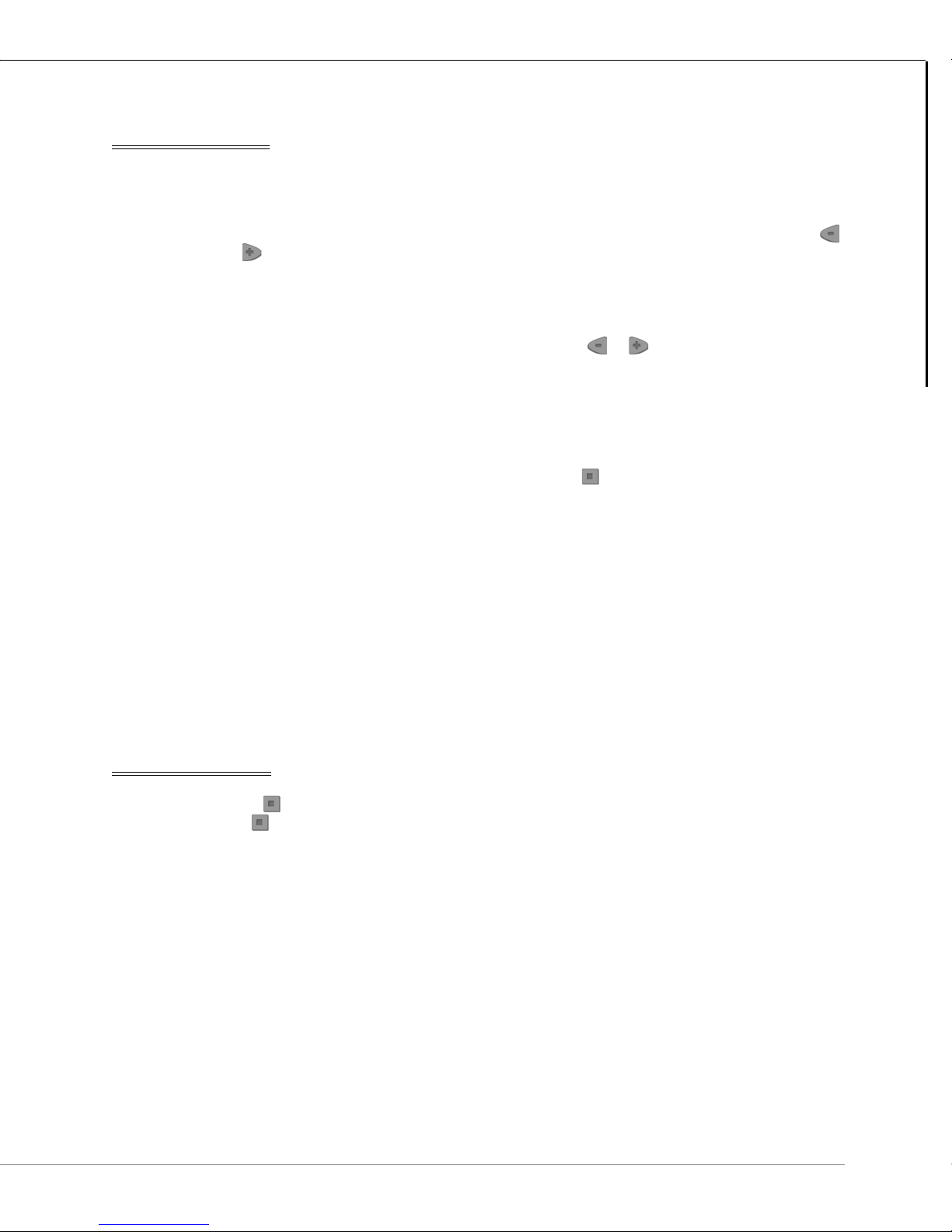
After the initialization sequence, hold the and buttons for five seconds,
release for two seconds, then press the button.
3 The LCD screen displays SSADDR and the current address of the SS-L. The
default SS-L address is 1.
FIGURE 45: SS-L ADDRESS SCREEN
4
Press the or to configure the desired SS-L address between 1 and 16.
5 After the desired configuration is complete, allow the onboard configuration tool
to time-out. The LCD screen will revert to the standard operator display.
Do not skip SS-L addresses. When the host controller encounters the first blank
(unprogrammed) SS-L it will be interpreted as the last SS-L and communication with higher
addresses will not occur.
When addressing SS-Ls be mindful of the maximum number of SS-Ls supported by the
host controller.
To benefit from the full-functionality of the SMART-Sensor™ LCD, firmware version 6.35, or
higher, must be installed in the host controller. System data and SMART-Sensor
configuration must be input using RC-Studio
2004 – 2014 Reliable Controls® Corporation. All rights reserved.
®
2.0, or higher.
USER GUIDE
™
LCD
47

SECONDARY POINT DISPLAY
The secondary point can be configured to display an additional value and descriptive
abbreviation on the idle screen of the display in the top row. This can be useful for
displaying the value of important space or system conditions such as setpoint, humidity
or CO
secondary display.
TO CHANGE THE SECONDARY DISPLAY POINT
1 The secondary point display may also be configured using the SS-L Addressing
from the host controller. Any of the ten SS-L display points can be selected as the
2
feature.
2
After the initialization sequence, hold the and buttons for five seconds,
release for two seconds, then press the button.
3 The LCD screen displays SSADDR and the current address of the SS-L. Press
the button to select the 2 DISP screen.
FIGURE 46: SS-L SECONDARY DISPLAY CONFIGURATION SCREEN
4
Press the or to configure the desired SS-L point to be displayed as the
secondary point.
5 After the desired configuration is complete, allow the onboard configuration tool
to time-out. The LCD screen will revert to the standard operator display.
48
2004 – 2014 Reliable Controls® Corporation. All rights reserved.

OPERATOR INTERFACE
SS-UD SS-S
O
PERATOR INTERFACE FOR THE SS
SETPOINT ADJUSTMENT OPTIONS
SS models can be ordered with optional Up/Down arrows (-UD) or the Slider (-S). These
options are typically used to control the temperature setpoint.
SMART-SENSOR
™
OPERATOR INTERFACE
Operator Interface for the SS
FIGURE 47: OPTIONAL UP/DOWN BUTTONS OR SLIDER ON AN SS
For SS models with the -UD or -S option, the buttons or slider affect point #2 on the
SMART-Sensor worksheet, called the Quick-adjust point. Moving the slider or pressing
the buttons will adjust the value of the Quick-adjust point, typically a setpoint.
TEST LED
SS models without the LCD screen have a Test LED located at the bottom of the circuit
board next to the onboard temperature sensor. The Test LED is used to prove wiring
integrity. After powering up the controller, the light is used to display test results. If
sufficient DC voltage is available (3.4 VDC), the light is enabled. If sufficient voltage is not
available, the light will remain off. If sufficient voltage is available and SMART-Net
communication is detected, the light will flash 8 times per second, for at least 2 minutes. If
sufficient voltage is available, but the SS cannot detect SMART-Net
light will stay on solid until power is cycled. To re-initiate the test, disconnect and
reconnect SMART-Net
2004 – 2014 Reliable Controls® Corporation. All rights reserved.
™
™
communications, the
™
.
USER GUIDE
49

FIGURE 48: TEST LED (SS AND SS-P SHOWN)
Test LED fully lit
Override button
OVERRIDE BUTTON
An SS model with an override button (-0), allows an operator to manually change the value
of a point mapped to point number 3 in the SMART-Sensor worksheet. The digital range
of ON/OFF must be used.
When the middle button on a model with an override button is pressed and point 3 is set
to digital ON/OFF, the digital value is set TRUE or ON and a 10 minute timer is initialized.
After 10 minutes has passed, the value of point 3 reverts to FALSE or OFF. The user is able
to force the value to FALSE either manually or with a Control-BASIC
™
program.
FIGURE 49: SS AND SS-P WITH OVERRIDE BUTTON (-O) OPTION
The -O option is often used to provide manual override of Unoccupied mode.
50
2004 – 2014 Reliable Controls® Corporation. All rights reserved.

OPERATOR INTERFACE FOR THE SS-L
Three-button keypad
SMART-SENSOR
™
OPERATOR INTERFACE
Operator Interface for the SS-L
The SMART-Sensor™ LCD (SS-L) allows for the display and adjustment of ten point values
®
from its SMART-Net host, which can be any Reliable Controls
MACH-System controller
except a SMART-Space Controller (SSC). The SMART-Space controller does not support
SMART-Net.
An SS-L can display points from networked controllers other than its SMART-Net host,
however those points cannot be adjusted by an operator using the SS-L buttons. If the
SMART-Net host is a BACnet only device (e.g., MACH-ProZone, MACH-ProAir), then any
network points to be displayed must be entered using BACnet references. If the SMARTNet host supports Reliable Controls Protocol (RCP), then any network points to be
displayed must be entered using RCP references.
Navigation through the configured LCD display screens and operator interaction with the
point values are both performed using the custom silicone rubber three button keypad.
The standard functionality of the buttons is outlined in Table 8.
FIGURE 50: SSL THREE-BUTTON KEYPAD
2004 – 2014 Reliable Controls® Corporation. All rights reserved.
USER GUIDE
51

TABLE 8: SSL INTERFACE BUTTON CONTROL
Top Row
Middle Row
Bottom Row
Button Functionality
LCD SCREEN INTERFACE
The SS-L features a 36 mm x 36 mm (1 3/8” x 1 3/8”) LCD display screen. This screen is
capable of displaying text and icons arranged in three rows as outlined in Table 9.
TABLE 9: SSL LCD SCREEN DISPLAY ROWS
Row Display
Pressing the center navigation button cycles the LCD display through each
of the configured point values.
Pressing the increment button will increase the value of analog points or
toggle the status of binary points configured to permit operator
modification.
Pressing the decrement button will decrease the value of analog points or
toggle the status of binary points configured to permit operator
modification.
To p
Six 7.62 mm (
5
/16”) alphanumeric characters may be used to display:
1) a short point name or, 2) the configured secondary point.
Middle
Four 15.24 mm (
5
/8”) alphanumeric characters used to display the
present value of the configured point. The units of the point may also
be displayed.
Bottom Up to six simultaneous unique icons may be displayed to indicate
system status (icon details in Table 10).
FIGURE 51: SS-L LCD SCREEN DISPLAY
52
2004 – 2014 Reliable Controls® Corporation. All rights reserved.

SMART-SENSOR
Degree C/F switch
Operator Interface for the SS-L
Up to seven icons may be configured along the bottom row of the SS-L LCD screen to
display system status. A description of the seven available icons is detailed in Table 10.
TABLE 10: SS-L SCREEN DISPLAY ICONS
Icon Description
Auto
Manual
Cool
Heat
Fan status/low speed
™
OPERATOR INTERFACE
While an SS-L may be freely configured to display ten user-defined data points and
BACnet
numbers are reserved for onboard input and output options if present. Refer to the SS-L
Programming section of this manual for a list of the reserved point numbers.
DEGREE C/F SWITCH
SS-L models with the -D option have a degree C/F switch used for selecting degrees
Celsius or Fahrenheit on display units. Sliding the switch to the left selects degrees C while
sliding to the right selects degrees F. The Degree C/F switch only invokes a local
conversion on the SS-L-D. It does not affect RC-Studio
BASIC
Fan medium speed
Fan high speed
®
object values from any Reliable Controls® MACH-System controller, specific point
®
™
functionality in any way.
System Groups or Control-
FIGURE 52: SS-L-D SHOWING THE DEGREE C/F SWITCH
2004 – 2014 Reliable Controls® Corporation. All rights reserved.
USER GUIDE
53

DISPLAY MODES
IDLE/DEFAULT MODE
The SS-L LCD has three main display modes: Idle (the default), Quick-adjust, and Display
point.
Idle mode is the SS-L's default screen display. If there has not been any button activity on
the SS-L for 20 seconds, the display will automatically revert to the default screen.
The default screen displays the present value of the point or object configured in row
number one of the SS-L worksheet in the center (or middle row) of the LCD.
Any points or objects configured to appear as an icon will be displayed in the bottom row
of the default LCD screen.
FIGURE 53: SS-L IDLE MODE DISPLAYING POINT DESCRIPTOR
SECONDARY POINT
If the secondary point is enabled in the SMART-Sensor Setup dialog box, the present
value of the point or object configured as the secondary point will be displayed in the top
row of the default LCD together with the programmed two-character abbreviation.
FIGURE 54: SS-L IDLE MODE DISPLAYING SECONDARY POINT
54
2004 – 2014 Reliable Controls® Corporation. All rights reserved.
QUICK-ADJUST MODE
The SSL's Quick-adjust mode allows for easy operator adjustment of a setpoint.
When the SSL LCD is in Idle mode (displaying the default screen), pressing either the
or button will cause the SSL to go into Quick-adjust mode.
In Quick-adjust mode, the SS-L displays the present value for the point or object
configured in row number two of the SMART-Sensor worksheet. The display blinks to
indicate that the value can be modified. Pressing the or button further will decrease
or increase the point value, typically a setpoint. After the desired adjustment is complete,
the display will continue to flash briefly until the value is communicated to the controller.
After 20 seconds have elapsed without further button interaction, the display will revert to
the Idle mode. Alternatively, after the setpoint has been adjusted, the operator can
advance to the next point or object by pressing the button.
SMART-SENSOR
™
OPERATOR INTERFACE
Operator Interface for the SS-L
FIGURE 55: SS-L QUICK-ADJUST MODE
DISPLAY POINT MODE
If the button is pressed, the SS-L goes into Display Point mode. Continued pressing of
the button will scroll through the configured points or objects according to the order in
which they were entered in the SMART-Sensor worksheet.
FIGURE 56: SS DISPLAY POINT MODE
USER GUIDE
2004 – 2014 Reliable Controls® Corporation. All rights reserved.
55

The present value or state of any point or object that is configured for Can Change in the
SMART-Sensor worksheet can be modified using the buttons of an SS-L. When editing the
quick adjust point (pressing left or right from the idle screen), the value will steadily blink on
the SS-L display.
BACKLIGHT FOR THE SS-L
Models with the optional backlight (-BL) allow for easier reading of the LCD display screen
in dim or dark environments. The backlight turns on whenever any of the buttons are
pressed and remains on for 10 seconds after last button press.
56
2004 – 2014 Reliable Controls® Corporation. All rights reserved.

SMART-SENSOR
Accessing the SS Worksheet
SOFTWARE PROGRAMMING
The SMART-Sensor™ LCD (SS-L) is custom configurable to display/adjust up to ten point values from
the host MACH-System controller. An SS-L can display points from networked controllers other than its
SMART-Net™ host, however those points cannot be adjusted by an operator using the SS-L buttons. If
the SMART-Net™ host is a BACnet only device (e.g., MACH-ProZone™, MACH-ProAir™), then any
network points to be displayed must be entered using BACnet references. If the SMART-Net™ host
supports Reliable Controls Protocol (RCP), then any network points to be displayed must be entered
using RCP references.
Software programming and configuration of an SS-L is performed using RC-Studio® 2.0, or higher.
ACCESSING THE SS WORKSHEET
TO ACCESS THE SMART-SENSOR WORKSHEET
™
SOFTWARE PROGRAMMING
1
In RC-Studio
the System Tree. If the System Tree is not visible, select Network > System
Tree or press Ctrl + P.
FIGURE 57: SYSTEM TREE COMMAND
®
2.0, locate the host controller of the SS-L to be programmed in
2004 – 2014 Reliable Controls® Corporation. All rights reserved.
USER GUIDE
57

2
Expand the SMART-Net
™
network for any controller in the System Tree by
clicking the + next to the SMART-Sensors node. A list of available SMART-
Sensor worksheets is displayed. There is a separate worksheet for each
™
possible SS SMART-Net
address based on the host controller type.
FIGURE 58: SSL WORKSHEETS IN A MACH-PROSYS™ & MACH-STAT
™
58
2004 – 2014 Reliable Controls® Corporation. All rights reserved.
SMART-SENSOR
™
SOFTWARE PROGRAMMING
Accessing the SS Worksheet
3
To configure the display of a specific SMART-Sensor
™
LCD, use the SMART-
Sensor worksheet.
To open the worksheet, click the desired sensor from the SMART-Sensors node
in the System Tree.
In Figure 59, Sensor #1 is selected to configure the SS-L at address number 1.
FIGURE 59: SELECT AN SMART-SENSOR WORKSHEET
FIGURE 60: SMART-SENSOR 1 WORKSHEET
2004 – 2014 Reliable Controls® Corporation. All rights reserved.
USER GUIDE
59

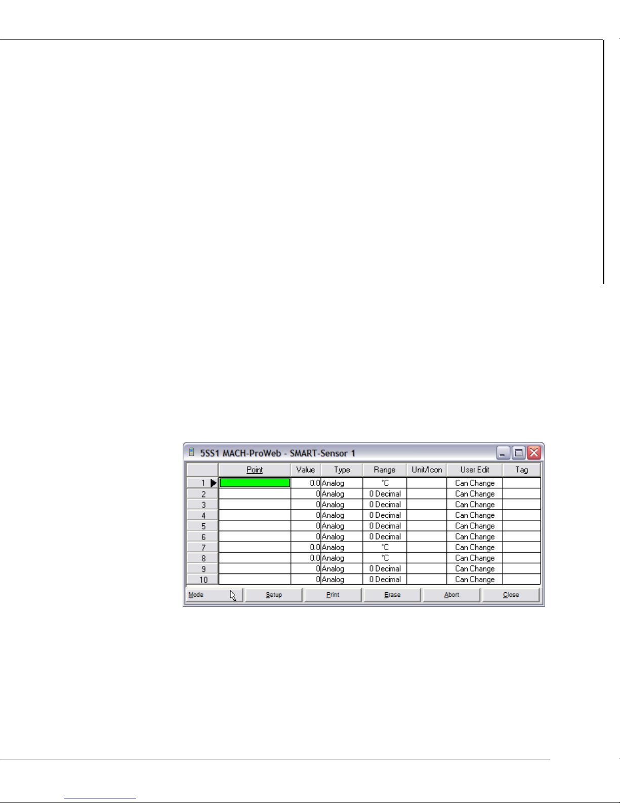
THE SS WORKSHEET
FIGURE 61: SMART-SENSOR 1 WORKSHEET
VALUES DISPLAYED
The SMART-Sensor worksheet has ten rows. Each row (1–10) corresponds to the values
that will be displayed on the LCD of the SS-L and the order in which they will appear.
The point or object that is defined to be displayed in row number one will be displayed
when the SS-L is in Idle mode.
The point or object that is defined to be displayed in row number two is the quick-adjust
point. If a user presses either the or button while the SS-L is in Idle mode, the
present value of the point defined in row two will be displayed.
If the point or object in row two is set to Can Change in the User Edit column, when the
value is accessed as the quick-adjust point, the value will be displayed flashing steadily and
may be modified. If, however, the point or object is configured to Display Only in the User
Edit column then the value will still be displayed and will still flash steadily, but the value will
not be modified in the controller.
The SS-L only supports one decimal place. When the SS-L is configured for two decimals,
the value will display properly in RC-Studio
®
, but the SS-L will show only one decimal place.
On the SS-L display, a value of 5 or less on the second decimal place will round down, while
®
a value of 6 or more will round up. For example, a value of 71.15 shown in RC-Studio
, will
be displayed as 71.1 on the SS-L. And 71.16 will be displayed as 71.2 on the SS-L.
60
2004 – 2014 Reliable Controls® Corporation. All rights reserved.

RESERVED POINTS
Each row of the SMART-Sensor worksheet may be used to configure any point or object
from any MACH-System controller for display. However, many of the rows also have
reserved functions associated with hardware features of individual SS models. To use any
of the onboard sensors or I/O, the points must be mapped to the appropriate reserved row
on the SS. Table 11 outlines the reserved points.
TABLE 11: SS RESERVED POINTS
Point Description
Point 1 Onboard temperature sensor
Point 2 Quick-adjust point (for -S or -UD models)
Point 3 Override button (for -O models only) when the range is set to On/Off
Point 4 Onboard humidity sensor (for -H models and SS-DUCT-EH-RH only)
Point 5 Onboard motion sensor (for -OC models only)
SMART-SENSOR
The SS Worksheet
™
SOFTWARE PROGRAMMING
Point 6 Onboard CO2 sensor (for -CO2 models only)
Point 7 -40 to 120 °C (-40 to 248 °F) thermistor or dry-contact input (for -IO
models only)
Point 8 -40 to 120 °C (-40 to 248 °F) thermistor or dry-contact input (for -IO
models only)
Point 9 TRIAC output 24 VAC @ 0.5 A (for -IO models only)
Point 10 TRIAC output 24 VAC @ 0.5 A (for -IO models only)
-DUCT and -P models have solid-state relays.
If the range for point 1 is changed to something other than degrees Fahrenheit (°F) or
degrees Celsius (°C), the onboard temperature thermistor will not be measured. Point 1
may then be mapped to any other point as desired.
For SS models without the onboard options listed above, the reserved rows may be
mapped to any point or object in the host controller.
2004 – 2014 Reliable Controls® Corporation. All rights reserved.
USER GUIDE
61

COLUMNS
The function of each of the eight columns in the SMART-Sensor worksheet are outlined in
Table 12.
TABLE 12: SS WORKSHEET COLUMNS
Column Description
Point Enter the point mnemonic or descriptor of an existing point or
object in the host controller to map it to the SS-L display. Points
may also be dragged from host controller worksheets and
dropped into this column.
Value Displays the present value.
Typ e Toggles between Analog or State to match the type of the object.
Range Scrolls through the available ranges associated with the Type
chosen, allowing selection of an appropriate display range for the
value.
State Off/On, Low/High, Cool/Heat, Off/Low/High,
Off/On/Auto, Fan: Off/Low/Medium/High, Off/
Auto/Manual, Cool/Heat/Auto/Off
Analog 0 Decimal, 1 Decimal, 2 Decimal, Time
Unit/Icon
(Analog)
Unit/Icon
(State)
For analog value types, the Unit/Icon field allows for the selection
of engineering units to be displayed on the LCD next to the value.
Blank No icon is displayed
Degrees Celsius
Degrees Fahrenheit
Percent
For state value types, the Unit/Icon field allows for the selection of
an icon to be displayed during the Idle mode.
Heat Icon is displayed when value = 1
Cool Icon is displayed when value = 1
Cool/Heat Icon is displayed when value = 0
Icon is displayed when value = 1
Manual Icon is displayed when value = 1
62
Auto
Icon is displayed when value = 1
2004 – 2014 Reliable Controls® Corporation. All rights reserved.
TABLE 12: SS WORKSHEET COLUMNS
Column Description
SMART-SENSOR
The SS Worksheet
™
SOFTWARE PROGRAMMING
Off/Auto/
No icon is displayed when value = 0
Manual
Icon is displayed when value = 1
Icon is displayed when value = 2
Fan Speed No icon is displayed when value = 0
Icon is displayed when value = 1
Icon is displayed when value = 2
Icon is displayed when value = 3
User Edit Toggles between Can Change, indicating that the value may be
modified by an operator and/or the SS; and Display Only, meaning
that the value cannot be changed by an operator or by the SS.
Ta g Six character descriptive name that will be displayed on the LCD
screen together with the present value when the operator scrolls
to the point. If this column field is left empty, the row number will
be displayed. Typing the value “_ND“ in the Tag field will cause
that point to be suppressed on the LCD, but that point’s data will
still be available from the SMART-Sensor worksheet.
If a point is configured with the Type set to State, an icon is selected, and the User Edit field
is set to Display Only, the icon will be displayed, according to the value of the point, in Idle
mode but the point will not appear
button.
New points may not be created in an SS. Every point used on an SS must already exist in a
MACH-System controller.
2004 – 2014 Reliable Controls® Corporation. All rights reserved.
separately by scrolling through the points using the
USER GUIDE
63

COMMAND BAR
The command bar is located along the bottom of the SMART-Sensor worksheet and has
six buttons as detailed in Table 13.
TABLE 13: SSL WORKSHEET COMMAND BAR
Point Description
Mode
Used to toggle the worksheet between Update , Select and
Edit mode.
If the icon is displayed, values on the worksheet are static and
will not automatically refresh with current data. In this mode, any
field may be selected for modification.
If the icon is displayed, the vale in the field selected may be
edited. In this mode, data is not dynamically updated.
When the mode is toggled from mode or mode to mode,
the current configuration and entries in the worksheet are sent
®
from RC-Studio
2.0 to the controller. In this Update mode, current
data is loaded from the controller into the worksheet in
®
accordance with the RC-Studio
2.0 refresh rate.
Setup Opens the SMART-Sensor Setup dialog box (described later in
this section).
Print Prints the worksheet.
Erase Clears all worksheet entries and returns all fields to default values.
Abort Cancels all changes made to the worksheet since the last save
and reloads the configuration from the controller.
Close Closes the worksheet. If there are any unsaved modifications, the
SMART-SENSOR SETUP DIALOG BOX
The SMART-Sensor Setup dialog box can be opened by clicking on the Setup button on
the SMART-Sensor worksheet command bar.
The fields of the SMART-Sensor Setup dialog box are detailed in Table 14.
64
user will be prompted to save the changes to the controller
2004 – 2014 Reliable Controls® Corporation. All rights reserved.

SMART-SENSOR
The SS Worksheet
FIGURE 62: SMART-SENSOR SETUP DIALOG BOX
TABLE 14: SMART-SENSOR SETUP DIALOG BOX
Field Description
Calibration Used to calibrate the onboard temperature sensor ± 3.1 degrees
in °C or °F.
™
SOFTWARE PROGRAMMING
Humidity
Calibration
Secondary
Point
Used to calibrate the onboard humidity sensor ± 31 percent in
%RH (-H models only).
Abbreviation Two character abbreviated name to be displayed
preceding the value of the secondary-point in Idle
mode.
Enable Enables the display of the secondary point on the
top row of the LCD in Idle mode rather than the Tag
for Point 1.
Auto Blanking The LCD reverts to the idle screen after 20 seconds of button
inactivity. When Auto Blanking is enabled, the LCD automatically
turns off after 20 seconds of button inactivity in the idle screen (40
seconds of inactivity before screen blanking occurs). The display
will reappear in Idle mode when any button is pressed.
Disable
Configuration
SMART-Sensor
Name
Locks out the configuration abilities of the SS-L inherent in the
firmware. If this box is enabled, the SS-L may not be used as a
™
SETUP-Tool
or Flow Tool.
Twenty character name for the SMART-Sensor™ LCD that will
appear in the SMART-Sensor worksheet title bar and the System
Tree.
If Time is selected as the Range for the secondary point, the abbreviation will not be shown.
Instead, AM or PM will be displayed.
2004 – 2014 Reliable Controls® Corporation. All rights reserved.
USER GUIDE
65

INPUT/OUTPUT POINT OPTION (-IO)
TRIAC 1 & 2
Input 1 & 2
* SSR 1 & 2
Input 1 & 2
SS-DUCT-IO
* SS-DUCT models use solid-state relays
(SSR) to switch AC or DC.
SMART-Sensor™ models with the -IO option feature two TRIAC outputs (except SS-DUCT models have
solid-state relays that switch AC or DC), and two onboard dry-contact/10k thermistor inputs. These
inputs and outputs may be used to connect ancillary space-related field devices without consuming
inputs and outputs on the host controller.
FIGURE 63: INTERNAL VIEW OF A SS-S-IO AND SS-DUCT-IO
INPUTS
The SS-IO inputs may be used to connect either dry-contacts or 10 k thermistors. The field
devices wire directly to the input terminal block on the SS-IO. A variable (VAR) must be
66
created in the host controller to store the value of each input used. The variables that
represent the inputs are then referenced using row 7 and row 8 of the SMART-Sensor
worksheet. To permit the SS-IO to define the values of these variables, the User Edit
column must be configured for Can Change.
When the SS-IO inputs are configured for temperature, they have a maximum range of
-40 to 120 °C (-40 to 248 °F).
2004 – 2014 Reliable Controls® Corporation. All rights reserved.

SMART-SENSOR
Dry Contact
10k Thermistor
IN 1+
IN 1-
IN 2+
IN 2-
There is no hardware configuration necessary to define the inputs of an SS-IO. The
software configuration necessary to define each input is programmed in the SMART-
Sensor worksheet and detailed in Table 15.
TABLE 15: SS-IO INPUT PROGRAMMING DETAIL
Physical Characteristics SS Worksheet Configuration
Input Typ e Row Typ e Range
Input 1 Dry contact Row 7 State Off/On
10 k Thermistor Row 7 Analog °C or °F
Input 2 Dry contact Row 8 State Off/On
10 k Thermistor Row 8 Analog °C or °F
SS-IO models use a 10 k pull-up resistor against a 2.5 VDC reference voltage unlike the
traditional +5 V used for the auxiliary inputs.
™
INPUT/OUTPUT POINT OPTION (-IO)
Outputs
OUTPUTS
SS-IO inputs terminate consistent with all MACH series dry-contact/10k thermistor inputs
as detailed in the figure below.
FIGURE 64: SS-IO INPUT WIRING
Field devices wire directly to the output terminal block on the SS-IO. A variable must be
created in the host controller to store a value corresponding to each output. The variables
that represent the outputs are then referenced using row 9 and row 10 of the SMART-
Sensor worksheet. To permit an operator to change the values of outputs 9 and 10
through the SS-IO interface, the User Edit column must be set to a value of Can Change.
2004 – 2014 Reliable Controls® Corporation. All rights reserved.
USER GUIDE
67

There is no hardware configuration necessary to define the outputs of an SS-IO. The
LOAD
LOAD
Transformer
120 VAC
24 VAC
TRIAC 1
TRIAC 2
RTN-T 1
RTN-T 2
OUT1+
OUT2+
OUT1-
OUT2-
SS-DUCT
SS
LOAD
LOAD
Transformer
120 VAC
24 VAC
software configuration necessary to define each output is programmed in the SMART-
Sensor worksheet and detailed in Table 16.
T
ABLE 16: SS-IO OUTPUT PROGRAMMING DETAIL
Physical Characteristics SS Worksheet Configuration
Output Ty pe Row Typ e Range User Edit
Output 1 TRIAC* Row 9 State Off/On Display/Can Change
Output 2 TRIAC* Row 10 State Off/On Display/Can Change
* SS-DUCT-IO has solid state relay outputs that switch 24VAC/DC @ 0.5A.
SS-IO outputs terminate consistent with all MACH series TRIAC outputs as detailed in
Figure 65.
FIGURE 65: SS-IO AND SS-DUCT OUTPUT WIRING
68
2004 – 2014 Reliable Controls® Corporation. All rights reserved.

SMART-SENSOR
SS-IO input 1
SS-IO input 2
SS-IO output 1
SS-IO output 2
FIGURE 66: SS-IO WORKSHEET RESERVED POINTS
Reserved points for inputs and onboard sensors must be set to Can Change so that the SS
can write to variables in the host controller. Output points do not need to be set to Can
Change unless the operator will be allowed to adjust the points through the SSL-IO
interface.
™
INPUT/OUTPUT POINT OPTION (-IO)
Outputs
2004 – 2014 Reliable Controls® Corporation. All rights reserved.
USER GUIDE
69

CARBON DIOXIDE SENSOR OPTION (-CO2)
The CO2 sensor has replaced the duplex RJ11
jacks in -CO2 models
The backplate for -CO2 models has been made
deeper than the standard backplate.
SMART-Sensor™ models with a CO2 sensor (SS-CO2) feature a 0–2000 PPM CO2 sensor that can
accurately measure a space’s Carbon Dioxide levels within ±50 PPM. The CO
sensor has automatic
2
calibration built-in and only adds 2 mA current draw to the base model SS.
OVERVIEW
SMART-Sensor™ models with the -CO2 option have some significant differences from nonCO2 models, including:
• The duplex RJ11 connection port on the rear of the sensor head has been
removed to make room for the CO
sensor,
2
• A special backplate is included to compensate for the CO
sensor depth,
2
• The backplate has a small hole and plastic grommet for wire penetration,
• The SS-CO2 comes with both a manual and automatic calibration features,
and
• The PPM reading resolves to 1 PPM.
FIGURE 67: SS-CO2 MODEL CIRCUIT BOARD
70
2004 – 2014 Reliable Controls® Corporation. All rights reserved.

BACKPLATE
7.1 cm
(2
13
/16”)
1/2” wire grommet fits
two CAT5 cables.
12.1 cm
(4
3
/4”)
0.9 cm
(
3
/8”)
0.9 cm
(
3
/8”)
1.9 cm
(
3
/4”)
4.9 cm
(1
5
/16”)
8.3 cm
(3
1
/4”)
SMART-SENSOR
Backplate
™
CARBON DIOXIDE SENSOR OPTION (-CO2)
FIGURE 68: SS-CO2 BACKPLATE
Figure 68 indicates that the backplate for -CO2 models is noticeably thicker than the
standard SS backplate thickness of 0.15 cm. Note the small grommet in the center of the
backplate for wire penetration. This small opening will minimize unwanted drafts that may
exude from a wall, especially when no insulation is present.
The mounting holes have been shifted 6 mm downwards compared to the original
backplate, for better alignment. Alignment pilots are included to match the original
backplate to facilitate drilling if required.
2004 – 2014 Reliable Controls® Corporation. All rights reserved.
USER GUIDE
71

If unwanted air flow is entering the sensor from the wall cavity, the grommet may be sealed
with silicone sealant at the wire penetration point. This will prevent airflow within the wall
cavity from disturbing the reading. Silicone sealant outgassing will NOT damage the CO
sensor.
WIRING
The duplex RJ11 connection port on the rear of the sensor head has been removed to
make room for the CO
backplate which must be used for connecting models with the -CO2 option to SMARTNet
For more information, please refer to the Wiring Details section earlier in this document.
CALIBRATION
The CO2 sensor is factory calibrated, however, some calibration drift during shipping and
installation is typical. However, there are exceptions that will require the use of a built-in
automatic calibration algorithm. Specifically, when the lowest CO
space being monitored does not drop to about 400 PPM.
™
daisy-chain wiring.
sensor. There is a standard 6-pole wiring terminal block on the
2
levels in any enclosed
2
2
AUTOMATIC
For applications where the CO
sensor is exposed to fresh air CO2 concentrations of 400
2
ppm at least once per week, the automatic calibration routine will calibrate the sensor to
specification within about 3 weeks. For applications where the sensor is not exposed to
400 ppm concentrations at least once every two weeks, manual calibration may be carried
out to increase final accuracy. Both automatic and manual calibration methods are
described below.
Automatic calibration occurs once in the first 24 hours after a power cycle, and then recurs
every two weeks thereafter. The lowest CO
value recorded during the cycle is compared
2
to 400 ppm, then the sensor is calibrated by the difference of the two values.
72
2004 – 2014 Reliable Controls® Corporation. All rights reserved.

Concentration (PPM)
2
CO
1200
1100
1000
900
800
700
600
500
400
300
200
100
SMART-SENSOR
Calibration
™
CARBON DIOXIDE SENSOR OPTION (-CO2)
MANUAL
0
FIGURE 69: AUTOMATIC CALIBRATION ONCE EVERY TWO WEEKS
< Two Weeks >
If the lowest CO2 value recorded is 600 PPM, as shown in Figure 69, the sensor will be
automatically calibrated down by 200 ppm (600 - 400). In other words, the calibration will
offset all readings by minus 200.
The sensor must be exposed to fresh air at least once every two weeks for the automatic
calibration algorithm to provide an accurate calibration. It doesn't matter when the fresh air
will be sensed, just that it will be sensed at some point during the period.
In the above example, the lowest CO
value recorded by the sensor during the two-week
2
period was 600 ppm, resulting the sensor being automatically calibrated downwards by
200 ppm. If the lowest value recorded actually was 600 PPM, the sensor would be out of
calibration by 200 ppm following execution of the automatic calibration algorithm. For
applications such as continuously occupied rooms, or in densely populated cities, manual
calibration will be required.
Manual calibration should be performed on the CO2 sensor whenever the lowest CO
reading in the building does not drop to about 400 PPM at least once every two weeks.
2004 – 2014 Reliable Controls® Corporation. All rights reserved.
2
USER GUIDE
73
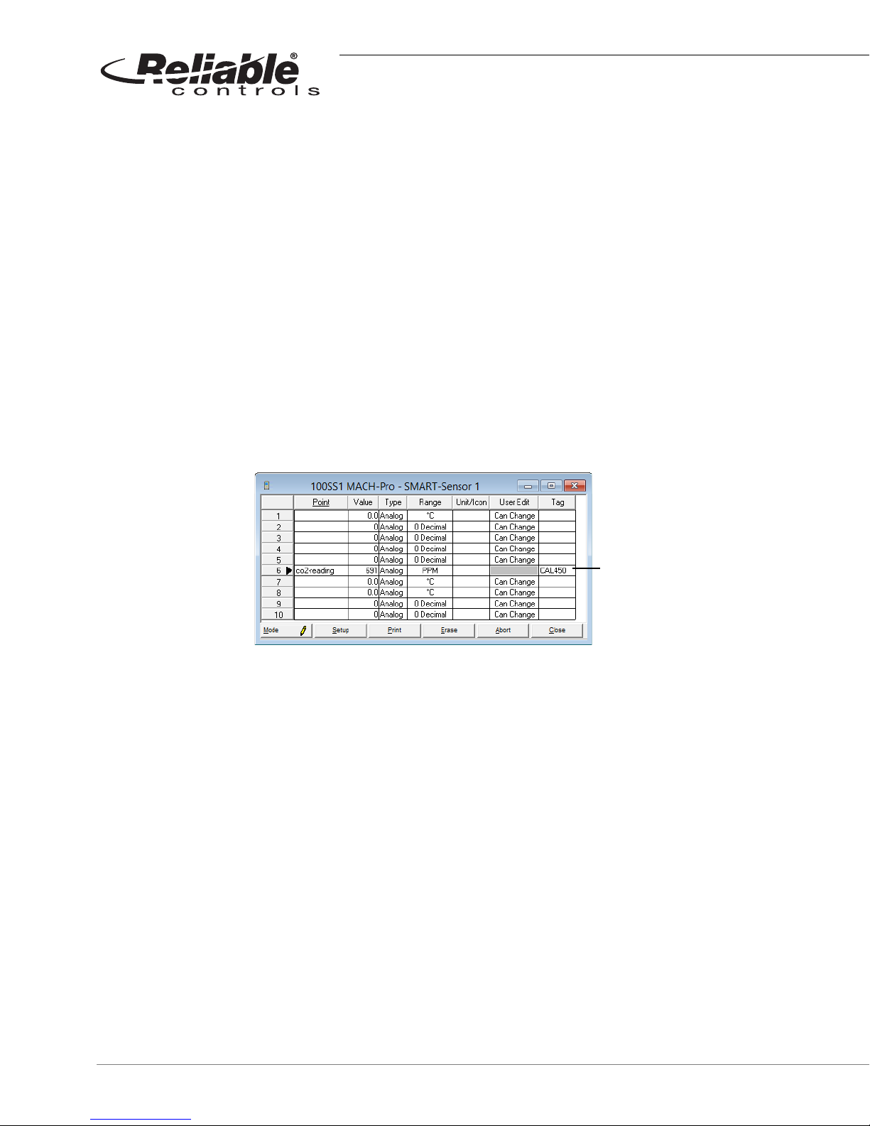
If the determination to manually calibrate the SS-CO2 has been made, follow the
procedure detailed below.
TO MANUALLY CALIBRATE THE CO2 SENSOR
1
2 Measure the CO
Open the appropriate SMART-Sensor worksheet in RC-Studio
with a reference sensor (this could be a handheld meter or a
2
known good sensor). Enter the reference CO
format CALXXX. Where the XXX value is the reference value. In the example
shown in Figure 70, the reference sensor measured 450 PPM, therefore CAL450
was entered in the Tag field.
FIGURE 70: SMART-SENSOR WORKSHEET MANUAL CALIBRATION USING THE TAG FIELD
3 Activate the Mode button to send the changes.
4 Deactivate the Mode button.
®
.
in PPM in the Tag field using the
2
The reading of 691 PPM
was calibrated to read 450
PPM by entering CAL450
in the Tag field.
5 The SMART-Sensor worksheet row number will highlight in orange when
calibration has been successful. Once this visual feedback is received, clear the
Tag field (VERY IMPORTANT).
6 Activate the Mode button again to send the changes.
7 Verify that the CO
perform steps 1 – 7 again.
74
value of the SS-CO2 matches the reference sensor. If not,
2
2004 – 2014 Reliable Controls® Corporation. All rights reserved.

CONFIGURATION
There are some important facts regarding configuration that should be remembered to
ensure the proper functionality of the SS-CO2 such as:
• Set the Type column value in the SMART-Sensor worksheet to Analog,
• Set the Range column value in the SMART-Sensor worksheet to PPM, and
• The PPM unit is not currently available on the LCD screen.
SMART-SENSOR
Configuration
™
2004 – 2014 Reliable Controls® Corporation. All rights reserved.
USER GUIDE
75

OCCUPANCY SENSOR OPTION (-OC)
Time
Time
Time
ton
ton
ton
td
td
td
ton - timer for
minimum on time,
SS state set to
false after ton
expires
td - delay time
for SS state to be
communicated to
the controller
Occupancy
Sensor
State
SS
Occupancy
State
Controller
Occupancy
State
True
True
True
False
False
False
The occupancy sensor installed in SMART-Sensors with the -OC option is capable of
detecting many motion events in a short amount of time. The SS occupancy protocol was
designed for setting the occupancy point (Point #5) as well as minimizing network traffic
over SMART-Net
after a fixed period of no motion. This fixed interval is referred to as ton (timer for minimum
occupancy ON time) and has a default of 10 minutes.
After an initial detection of motion, the occupancy sensor is in a True state. This, in turn,
sets the SS occupancy state and the controller occupancy state (Point #5) to a True state.
Whenever the occupancy sensor state transitions to the True state, the ton timer is reset
to the default. Whenever the occupancy sensor transitions to the False state, the ton timer
starts timing down. The occupancy sensor state may change many times, but the SS
occupancy state will remain True until the ton timer has counted down to zero following
the last motion sensed.
The state of the occupancy can be set to Unoccupied or False by the controller at any time
via Control-BASIC, or by manually adjusting Point #5 of the SMART-Sensor worksheet.
Setting Point#5 to False resets the ton timer back to the default. The ton timer will remain
at the default as long as the occupancy state is True and will start counting down to zero
only after a False state is detected. For more details, see Product Bulletin #4294.
™
. Traffic is minimized by only communicating changes in occupancy
FIGURE 71: SS OCCUPANCY SENSOR
76
2004 – 2014 Reliable Controls® Corporation. All rights reserved.

SMART-SENSOR
0°
50°
50°
0°
41°
41°
5 m
16 ft 5 in
2.5 m
8 ft 2 in
2.5 m
8 ft 2 in
5 m
16 ft 5 in
5 m
16 ft 5 in
2.5 m
8 ft 2 in
5 m
16 ft 5 in
2.5 m
8 ft 2 in
Plan View
Elevation View
Configuration
Figure 72 illustrates the viewing angles within which the occupancy sensor can detect
motion.
™
OCCUPANCY SENSOR OPTION (-OC)
FIGURE 72: MOTION DETECTION ANGLES
2004 – 2014 Reliable Controls® Corporation. All rights reserved.
USER GUIDE
77

DUCT OPTION (-DUCT)
Duct width
Duct width / 2
The SMART-Sensor™ with -DUCT option is capable of accurately reading air temperature
flowing within a standard air duct. But, to do so, the proper model with the appropriate
probe length should be chosen. The best model to choose will be the model with the tip
of the probe as close to the centerline of the duct as possible.
The simplest way to calculate the probe length needed is by taking the depth of the duct
and dividing by two. For instance, a 16 inch duct (as measured from the probe penetration
point to the oposite wall) would need an 8 inch probe. See Table 3 on page 20
number details.
for model
FIGURE 73: CROSS SECTION OF DUCT SHOWING THE SS-DUCT PROBE TIP PLACEMENT
78
2004 – 2014 Reliable Controls® Corporation. All rights reserved.

NETWORK COMMUNICATION JACK
RJ11 connector
SMART-Sensor™ models without the Slider (-S) option, the Duct (-DUCT) option, or the
Plate (-P) option, feature an RJ11 access port exposed conveniently on the bottom of the
SS sensor head. On an installed SS, this RJ11 access port may be used in conjunction
with an X-Port-2
and RC-Toolkit
™
converter to provide access to the host network using RC-Studio® 2.0
™
2.0.
SMART-SENSOR
Configuration
™
NETWORK COMMUNICATION JACK
FIGURE 74: SS-L RJ11 ACCESS PORT
The network jumpers or switches (NET) on MACH-System controllers and SSX expansion
™
boards connect the A and B pins of the SMART-Net
network to the controller’s EIA-485
communication network, effectively extending the local controller network to the SS RJ11
™
access port. An X-Port-2
the EIA-232 port of a PC, allows network access for RC-Studio
plugged into an enabled SS RJ11 port, and also plugged into
®
and RC-Toolkit
applications.
™
The MACH-ProZone
and MACH-ProAir™ controllers do not have Net switches or jumpers.
If a six-wire connection is made to the RJ11 port on the controller, the EIA-485 network is
™
extended to SMART-Net
. Use the 4-pole terminal block provided to avoid extending the
EIA-485 network, if not required.
To enable network communication with the X-Port-2™ converter, the EIA-485 network
jumpers (NET) must be installed on the host controller and any SSX expansion boards to
which the SSL is connected.
®
2004 – 2014 Reliable Controls® Corporation. All rights reserved.
USER GUIDE
79
CONNECTING AN X-PORT-2 CONVERTER
USB-CNV converter
CC-VC-C cable
CC-C1-C cable
CC-C-B RJ11
to 9-pin adapter
TO CONNECT AN X- PORT-2 CONVERTER
1 Connect a 6-conductor rollover Voice Cable (SS-VC) with an RJ11 modular
connector to the RJ11 access port located on the bottom of the SS.
2
3
Connect the rollover SS-VC to the Network port of the X-Port-2™ converter.
Wait for the X-Port-2
™
converter to complete the start-up cycle. The PC/Modem
indicator light will flash once per second when the start-up cycle is complete.
4 Use the appropriate direct connect cabling necessary to connect the PC/
™
Modem port of the X-Port-2
converter to the serial port adapter of the
workstation (CC-C1-C cables, CC-C1-B, RJ/11 to 9-pin adaptor, and CNV-USB232, as detailed below are standard part numbers available from Reliable
®
Controls
).
FIGURE 75: X-PORT-2™ CONNECTION FROM AN SS-L-J TO A WORKSTATION
After a network connection is established, the X-Port-2™ converter automatically configures
itself to the network baud rate. Active network traffic is required to complete the
configuration. Start-up may take up to two minutes, depending on the network and
controller address. The start-up is complete when the PC/Modem light flashes once per
second.
™
The X-Port-2
converter must be allowed to complete the start-up process before a
connection to the system by a workstation can be attempted.
80
2004 – 2014 Reliable Controls® Corporation. All rights reserved.

ONBOARD CONFIGURATION TOOLS (SS-L)
Each SMART-Sensor™ LCD features onboard configuration tools as a component of the
firmware. These configuration tools may be used to provide hardware configuration of the
SSL and the host controller connected to the SS-L without requiring a PC connection and
software.
The onboard configuration tools embedded in the SS-L firmware are:
• SS-L Address Tool,
• Setup Tool, and
• Flow Tool.
Each individual onboard configuration tool is invoked by a unique key code combination
using the three-button keypad interface of the SS-L. Table 17 details the key code
combination necessary to access each configuration tool.
SMART-SENSOR
™
ONBOARD CONFIGURATION TOOLS (SS-L)
Connecting an X-Port-2 Converter
TABLE 17: SS-L ONBOARD CONFIGURATION TOOL KEY CODE COMBINATIONS
Point Description
SS-L Address Tool 1
Press and hold the and buttons for five
seconds.
2
3
Release the and buttons for two seconds.
Press the button.
4 SSLADDR should appear on the LCD with the current
SS-L address displayed.
Setup Tool 1
Press and hold the and buttons for five
seconds.
2
3
Release the and buttons for two seconds.
Press the button.
4 ADDR should appear on the LCD with the current host
controller RCP address displayed.
Flow Tool 1
Press and hold the , , and buttons for five
seconds.
2004 – 2014 Reliable Controls® Corporation. All rights reserved.
2
3
Release the , , and buttons for two seconds.
Press the button.
4 FLOW should appear on the LCD with the current
calculated airflow value of the connected MACH-Air
displayed.
USER GUIDE
™
81

After the appropriate onboard configuration tool has been invoked, the three-button key
pad is used to perform the necessary configuration of the SS-L or connected controller.
The and buttons are used to increase or decrease analog values or to change the
state of binary values displayed on the LCD. The button is used to step through the
configuration parameters.
SS-L ADDRESS TOOL
The onboard SS-L Address Tool is used to configure the SMART-Net™ address of the SSL and the secondary point.
TO USE THE SS-L ADDRESS TOOL
1 Access the SS-L Address Tool using the appropriate key code combination
outlined in Table 17.
2
3
SSLADDR will display the value of the SMART-Net
the or button to select the desired SMART-Net
Press the button to scroll to the 2DISP screen to display the SS-L point that is
™
address of the SS-L. Press
™
address between 1–16.
selected to be shown as the secondary point. Press the or button to
select the desired point to be displayed as the secondary point.
4 After the SS-L Address and secondary point are configured as desired, allow the
onboard configuration tool to time-out. The LCD screen will revert to the Idle
mode.
82
2004 – 2014 Reliable Controls® Corporation. All rights reserved.

SETUP TOOL
Reliable Controls® MACH-System controllers require several parameters to be configured
in order to successfully communicate to other controllers on an EIA-485 network. This
configuration may be performed using the SS-L onboard Setup Tool rather than using the
RC-Toolkit
The Setup Tool can be used to configure the following controllers:
™
MSet application and a workstation connection.
SMART-SENSOR
Setup Tool
™
ONBOARD CONFIGURATION TOOLS (SS-L)
• MACH1
™
• MACH2™,
™
• MACH-Air
• MACH-Stat
• MACH-Zone
• MACH-ProAir
• MACH-ProZone
,.
™
,
™
,
™
,
™
• MACH-Pro1™, and
™
• MACH-Pro2
.
2004 – 2014 Reliable Controls® Corporation. All rights reserved.
USER GUIDE
83

Table 18 describes the configuration parameters that can be accessed using the MSet
Setup Tool in each controller.
TABLE 18: SS-L ONBOARD MSET SETUP TOOL CONFIGURATION PARAMETERS
Parameter Range Selection
ADDR 1–124
BAUD
9600, 192,
384, 768
SUBNET
No, Yes
LAST
----, Last
BACNET
Yes, No
UPDATE
No, Yes
RCP Controller Address (BACnet
®
MAC address)
9600 EIA-485 network baud = 9.6 kbps
192 EIA-485 network baud = 19.2 kbps
384 EIA-485 network baud = 38.4 kbps
768 EIA-485 network baud = 76.8 kbps
No home network = main network
Yes home network = subnetwork
---- not highest physical address on RCP network
Last highest physical address on RCP network
Yes
communication protocol = BACnet
®
No communication protocol = RCP
No configuration maintained in SS-L buffer only
Yes configuration sent to controller
84
2004 – 2014 Reliable Controls® Corporation. All rights reserved.

SMART-SENSOR
TO USE THE SS-L SETUP TOOL
1 Access the Setup Tool using the appropriate key code combination outlined in
Ta b le 1 7.
2 ADDR will display the value of the RCP address for the connected controller.
Press the or button to select the desired RCP address between 1–124.
Press the button to scroll to the next parameter.
3 BAUD will display the value of the baud for the connected controller. Press the
or button to select the desired baud for the network. Press the button
to scroll to the next parameter.
4 SUBNET will display a value of Yes or No. The value should display a Yes if the
controller resides on a subnetwork. The value should display a No if the
controller resides on a main network. Press the or button to select the
desired value. Press the button to scroll to the next parameter.
™
ONBOARD CONFIGURATION TOOLS (SS-L)
Setup Tool
5 LAST will display a value of ---- or Last. The value should display a ---- if the
®
controller is not the highest physical address on an RCP or BACnet
network.
The value should display a Last if the controller is the highest physical address
on an RCP network. Press the or button to select the desired value. Press
the button to scroll to the next parameter.
6
BACnet
network communication protocol is BACnet
®
will display a value of Yes or No. The value should display a Yes if the
®
. The value should display a No if
the network communication protocol is RCP. Press the or button to select
the desired value. Press the button to scroll to the next parameter.
7 IMPORTANT: UPDATE will display a value of Yes or No. When the value
displayed is a No, any modified configuration parameters are being stored in the
SS-L buffer, and not sent to the controller. Press the button to send the
configuration parameter settings from the buffer of the SS-L to the controller. To
commit changes to the controller, allow the device to restart and confirm that the
changes have been made, keep the SS-L connected to the device and do not
make any additional changes until the UPDATE value has returned to No.
2004 – 2014 Reliable Controls® Corporation. All rights reserved.
USER GUIDE
85

Last Panel is a software parameter used to facilitate efficient token passing on RCP
networks only. On RCP networks, the controller with the highest physical address (RCP
address) should be configured as the Last Panel. This Last Panel setting will remind the
controller to return the token to the controller with the lowest physical address. If later
expansion causes controllers to be added to the network and higher physical addresses to
be used, the Last Panel parameter will have to be modified to ---- in the device that no
longer has the highest physical address and set to Last in the new controller with the
highest physical address.
BACnet MS/TP networks do no utilize Last Panel to facilitate the token-passing scheme
®
implemented for communication. For this reason, on BACnet
networks, it is recommended
that Last Panel not be used. Therefore, no controllers would be configured as Last but all
would be configured with a value of ---- for the LAST parameter.
Changes to the MSet Set-Up parameters are initially stored in the buffer of the SS-L only. To
send the changes to the controller, UPDATE must be set to Yes. After the configuration
parameters are sent to the controller, the controller must reboot to commit the changes. Do
not unplug the SS-L, press any of the buttons or make any further modifications after the
UPDATE value has been set to Yes until it automatically resets to No.
For best practice, provide a couple of seconds for the SS-L buffer to properly parse each
configuration parameter modification before committing the changes to the controller by
setting UPDATE to Yes.
86
2004 – 2014 Reliable Controls® Corporation. All rights reserved.

FLOW TOOL
SMART-SENSOR
Flow Tool
™
ONBOARD CONFIGURATION TOOLS (SS-L)
The SS-L onboard Flow Tool can be used to perform standard Test and Balance airflow
™
calibration of MACH-Air
the base standard Reliable Controls
controllers used in variable air volume (VAV) applications utilizing
®
pan file.
The Flow Tool accesses pre-configured variables (VARs) in the standard pan file provided
™
in all MACH-Air
need for RC-Studio
controllers. These VARs may then be modified using the SS-L without a
®
2.0 and a workstation connection. The Flow Tool VARs are outlined
in Figure 76 and Table 19.
FIGURE 76: SS-L FLOW TOOL WORKSHEET IN THE STANDARD PAN FILE IN ALL MACH-AIR™ CONTROLLERS
The SSL onboard Flow Tool requires a pre-configured SS-L profile and several VARs that
are all featured in the Reliable Controls
®
standard MACH-Air™ and MACH-ProAir™ pan files.
For proper calibration using the Flow Tool, this pan file should be used.
™
In the standard MACH-Air
display configuration is pre-configured in Sensor-5 of the SMART-Sensor
a functional SS-L address for a MACH-(Pro)Air
and MACH-ProAir™ pan files, the SS-L onboard Flow Tool
™
™
. Do not attempt to change the SS-L
node. This is not
address to 5 in order to use the Flow Tool. Access to these parameters is automatically
provided by invoking the embedded SS-L Flow Tool in the firmware.
2004 – 2014 Reliable Controls® Corporation. All rights reserved.
USER GUIDE
87
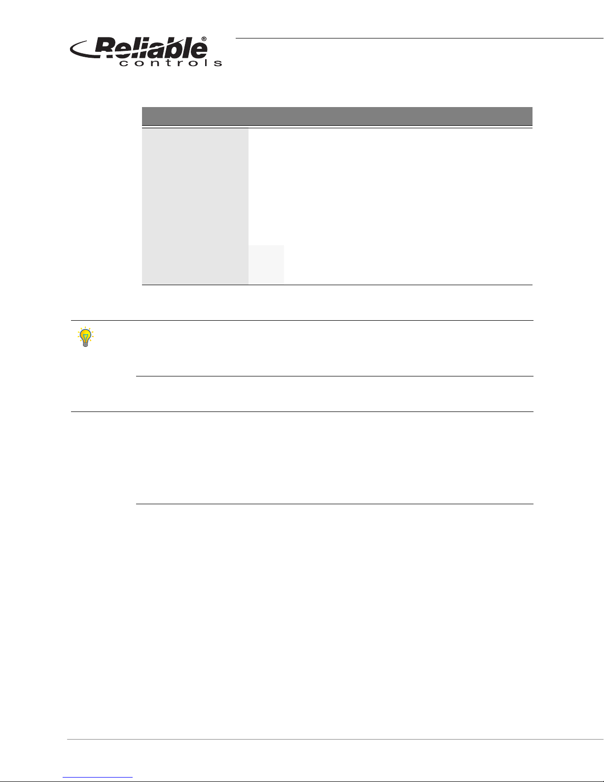
TABLE 19: SS-L ONBOARD FLOW TOOL CONFIGURATION PARAMETERS
Parameter Function
FLO Displays the current calculated measured flow
FL-CAL Used to enter the actual measured flow
FL-OVR Used to override the current airflow setpoint
FI-MIN Display/modify the minimum airflow setpoint
F-MAXO Display/modify the maximum occupied airflow setpoint
F-MAXU Display/modify the maximum unoccupied airflow setpoint
Off Actuator rotation counter-clockwise to close damper
CW-CLS
On Actuator rotation clockwise to close damper
Before using the Flow Tool to perform airflow calibration of a MACH-Air™ or MACH-ProAir
controller, set the minimum (VAVx-FLO-MIN) and maximum airflow setpoints (VAVx-FLOMAX-OCC, the VAV box inlet duct diameter (VAVx-DIAM-IN) and the damper actuator
rotation direction to close (VAVx-CW-CLS).
The following MACH-Air™/MACH-ProAir™ airflow calibration procedure as outlined in
Reliable Controls
®
Application Notice 0009 assumes a functional and configured controller.
The calibration procedure requires stable duct static pressure. The central air handling
system should be controlling to the design duct static pressure setpoint. Significant
changes to the VAV box inlet static pressure during the calibration procedure will result in an
inaccurate calibration. For best practice, set all connected VAV boxes to 50% of the
maximum flow setpoint using the FLO-SP-OVR variable.
™
88
2004 – 2014 Reliable Controls® Corporation. All rights reserved.
SMART-SENSOR
TO USE THE SS-L FLOW TOOL
1 Access the Flow Tool using the appropriate key code combination outlined in
Ta b le 1 7.
™
ONBOARD CONFIGURATION TOOLS (SS-L)
Flow Tool
2
Use the button to step to the FL-OVR point on the SS-L. Then use the
and buttons to override the current airflow setpoint to the maximum
occupied airflow setpoint for the connected VAV box.
FIGURE 77: SS-L FL-OVR POINT
3
Use the button to step to the FLOW point on the SS-L and wait until the
displayed calculated flow stabilizes (depending upon system conditions and
flow sensor calibration, the displayed flow may not reach the FL-OVR setpoint).
FIGURE 78: SS-L FLOW POINT
4 Determine the actual VAV box total airflow by measuring the airflow through
each connected distribution outlet using an accurate balancing hood.
5
For this example, the initial calculated flow is 600 CFM but the actual measured
total flow is 650 CFM.
Use the button to step to the FL-CAL point on the SS-L. Then use the
and buttons to increment the value to the actual total measured airflow
recorded in step 4.
FIGURE 79: SS-L FL-CAL POINT
USER GUIDE
2004 – 2014 Reliable Controls® Corporation. All rights reserved.
89
6 Wait until the FL-CAL point value resets to 0. This may take up to one minute.
During this time the MACH-Air
FIGURE 80: SS-L FL-CAL POINT
™
is calibrating the airflow sensor.
7 When the FL-CAL point value reads 0, the K-factor constant multiplier for the VAV
box has been set and the airflow transducer has been calibrated.
8
Use the button to step to the FLOW point on the SS-L and wait until the
displayed calculated flow stabilizes near the FL-OVR setting.
FIGURE 81: SS-L FLOW POINT
9 For best practice, verify the total actual flow by measuring the airflow through
each connected distribution outlet using an accurate balancing hood again. If
the difference between the actual total measured airflow and calculated total
airflow displayed by the SS-L is outside of the specified or acceptable limits (5%
- 10% typical), repeat steps 5–8.
1 0 If it is necessary to balance or test the VAV box at the configured minimum
airflow setpoint, repeat steps 2–4 using the minimum airflow setpoint for the FLOVR value.
The actual total measured airflow with the box operating at the minimum flow
setpoint may be measured. However, do not re-calibrate the K-factor based
upon the minimum airflow setting. The flow transducer is more accurate at
higher air velocity.
1 1
Set the FL-OVR point value back to 0 to allow the MACH-Air
programmed operation.
1 2 The calibration procedure is now complete.
A typical value for the K-factor of a MACH-Air™/MACH-ProAir™ is from 0.5 to 1.5. If the
calculated value is outside of this range, there is likely a problem. Most airflow pickups
amplify the differential pressure to allow for a better resolution of the signal by the
differential pressure transducer. For this reason, the constant multiplier K is usually < 1.0 in
order to remove the amplification.
90
™
to revert to normal,
2004 – 2014 Reliable Controls® Corporation. All rights reserved.

SMART-SENSOR
™
ONBOARD CONFIGURATION TOOLS (SS-L)
Disable SS-L Configuration Tools
The FL-OVR parameter must be set back to 0 when the calibration procedure is complete to
allow the MACH-Air
™
to revert to normal programmed operation. This VAR overrides the
control airflow setpoint and any value > 0 will prevent the MACH-Air
programmed.
DISABLE SS-L CONFIGURATION TOOLS
If desired, the SS-L onboard configuration tools can be disabled, thereby preventing operators from accessing any of the configuration tools by entering the key code combinations.
TO DISABLE THE ONBOARD CONFIGURATION TOOLS
1 Connect to the system and open the SMART-Sensor worksheet of the desired
SS-L in RC-Studio
2 Click the Setup button to open the SMART-Sensor Setup dialog box.
3 Enable the Disable Configuration checkbox.
®
2.0 as outlined in this manual.
™
from controlling as
FIGURE 82: SMART-SENSOR SETUP DIALOG BOX WITH DISABLE CONFIGURATION CHECKED
4 Click the OK button to close the SMART-Sensor Setup dialog box.
5
Click the Mode button to toggle the SMART-Sensor worksheet to the mode
to save the change and commit it to the controller.
2004 – 2014 Reliable Controls® Corporation. All rights reserved.
USER GUIDE
91
 Loading...