

Page 1
Features
• cULus Listed as Residential Sprinklers
• Push-On cover plate installation
• Low water flow requirements
Product Description
Model RFC Series residential sprinklers are flat cover plate,
concealed pendent sprinklers intended for installation in
accordance with NFPA 13, NFPA 13R, or NFPA 13D. The
sprinklers are cULus Listed as Residential Sprinklers in accordance with UL 1626. In addition, Model RFCLL Series
sprinklers are cULus Certified for Health Effects to NSF/ANSI
standard 61 Annex G (LL) and Australian WaterMark Certified
(WMCS).
Bulletin 006 May 2019
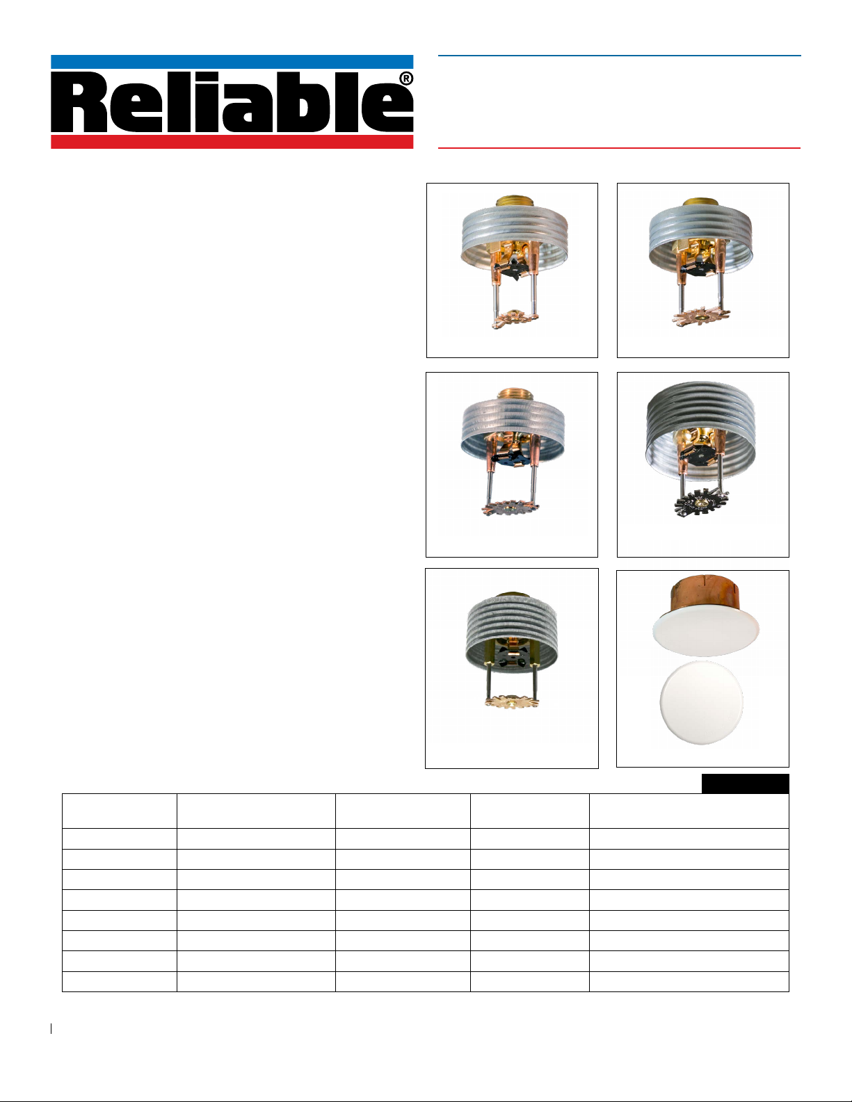
Model RFC Series Residential Sprinklers
Flat Concealed Pendent
cULus Listed
Model RFC43 & RFC43LLModel RFC30 & RFC30LL
Model RFC30 sprinklers have a 165°F (74°C) temperature
rated fusible-link operating element. Model RFC43, RFC49,
RFC58, and RFC76 sprinklers are offered with either a 165°F
(74°C) or 212°F (100°C) temperature rated fusible-link operating element. Sprinklers with a 165°F (74°C) temperature
Model RFC49 & RFC49LL Model RFC58
rating are ordinary temperature classification and are listed
for use with a 135°F (57°C) temperature rated cover plate.
Sprinklers with a 212°F (100°C) temperature rating are intermediate temperature classification and are listed for use with
a 165°F (74°C) temperature rated cover plate.
Model RFC Series sprinklers are installed with a Model RFC
cover plate. Model RFC cover plates may be installed by either pushing or threading the cover plate into the sprinkler
cup. Model RFC30, RFC30LL, RFC43, RFC43LL, RFC49 and
RFC49LL sprinklers allow 1/2” (13 mm) of cover plate adjustment. Model RFC58 and RFC76 sprinklers allow 3/4” (19 mm)
of cover plate adjustment. Model RFC cover plates are avail-
Model RFC76
able in a variety of finishes as listed in Table H.
Sprinkler Model
Nominal K-Factor
gpm/psi
1/2
(l/min/bar
Max. Coverage Area
1/2
)
ft x ft (m x m)
Listings &
Approvals
Sprinkler Identification
RFC30 3.0 (43) 14 x 14 (4.3 x 4.3) cULus RA0611
RFC30LL 3.0 (43) 14 x 14 (4.3 x 4.3) cULus, LL, WMCS RA3211
RFC43 4.3 (62) 20 x 20 (6.1 x 6.1) cULus RA0612
RFC43LL 4.3 (62) 20 x 20 (6.1 x 6.1) cULus, LL, WMCS RA3212
RFC49 4.9 (71) 20 x 20 (6.1 x 6.1) cULus RA0616
RFC49LL 4.9 (71) 20 x 20 (6.1 x 6.1) cULus, LL, WMCS RA3216
RFC58 5.8 (84) 20 x 20 (6.1 x 6.1) cULus RA0613
RFC76 7.6 (109) 20 x 20 (6.1 x 6.1) cULus RA0618
cULus: cULus Listed to UL1626, Residential Sprinklers for Fire Protection Service.
LL: cULus Certified for Health Effects to NSF/ANSI Standard 61 Annex G (Less than 0.25% Lead content).
WMCS: Australian WaterMark Certified.
Model RFC Cover Plate
Table A
Number (SIN)
www.reliablesprinkler.com
Page 2
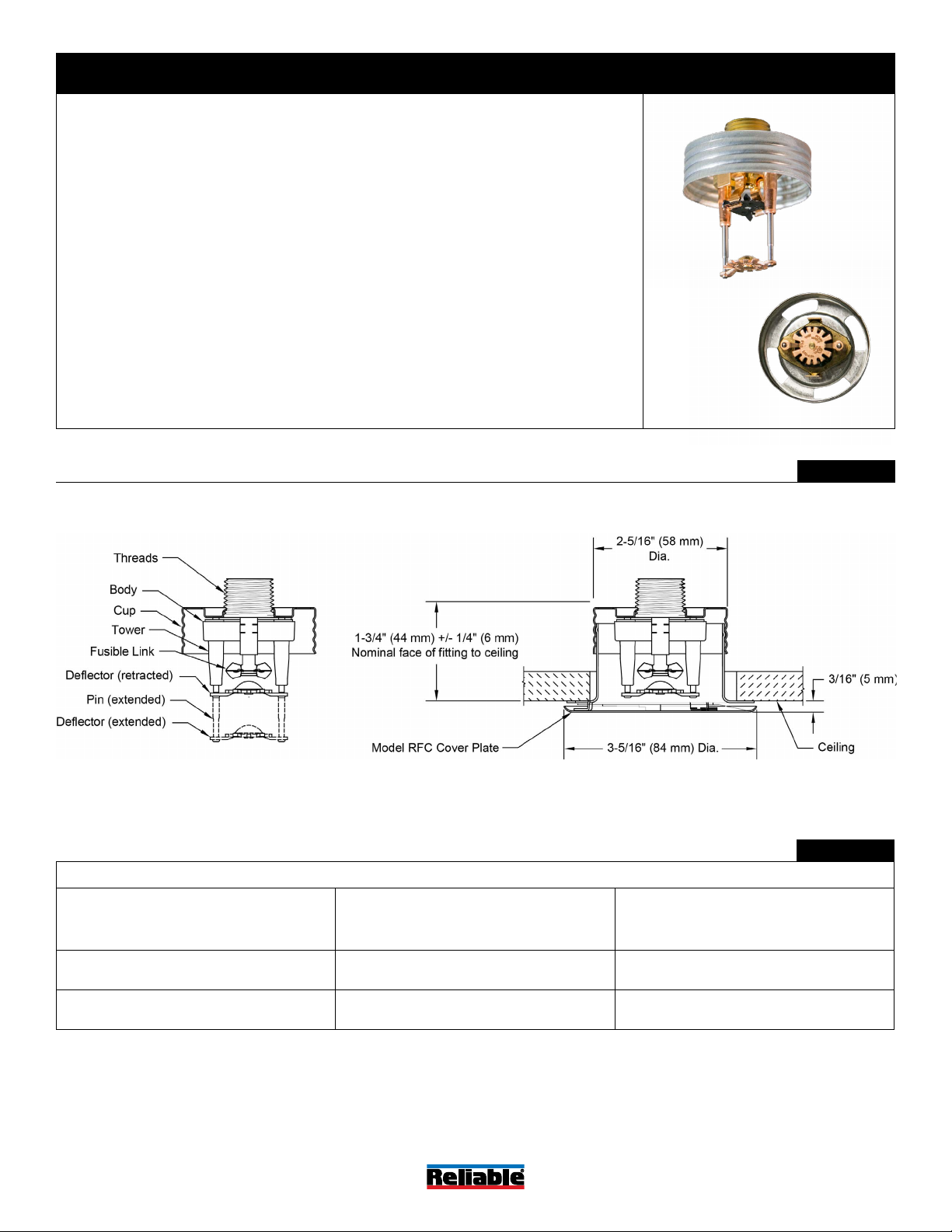
Model RFC30 & RFC30LL Residential Sprinklers
Technical Specifications
Style: Flat Concealed Pendent
Threads: 1/2” NPT or ISO 7-1R1/2
Nominal K-Factor: 3.0 (43 metric)
Max. Working Pressure: 175 psi (12 bar)
Min. Spacing: 8 ft. (2.4 m)
Material Specifications
Thermal Sensor: Nickel Alloy Solder Link
Sprinkler Body: Brass Alloy
Levers: Bronze Alloy
Yoke: Brass Alloy
Sealing Assembly: Nickel Alloy with PTFE
Load Screw: Bronze Alloy
Towers: Copper Alloy
Pins: Stainless Steel
Deflector: Bronze Alloy
Cup: Steel
Cover Plate Finishes
(See Table H)
Sensitivity
Fast-response
Temperature Rating
165°F (74°C) sprinkler
135°F (57°C) cover plate
Cover Plate
Model RFC cover plate
Sprinkler Wrench
Model FC (without wrench-able cap)
Model W3 (with wrench-able cap)
Listings and Approvals
cULus Listed to UL 1626
cULus Certified for Health Effects to NSF/ANSI
Standard 61 Annex G (RFC30LL only)
Watermark Certified (RFC30LL only)
RFC30: SINRA0611
RFC30LL: SINRA3211
Bottom View
Model RFC30 & RFC30LL Sprinkler Components and Dimensions
Model RFC30 and RFC30LL Sprinkler Hydraulic Design Criteria
Minimum Flow and Residual Pressure
Max. Coverage Area
ft. x ft.
(m x m)
12 x 12
(3.6 x 3.6)
14 x 14
(4.3 x 4.3)
Notes:
1. For NFPA 13 installations the flow per sprinkler must be the greater of: (1) the flow listed in Table B above and (2) the flow required to
achieve a minimum design density of 0.1 gpm/sq ft over the design area of the sprinkler.
2. For coverage area dimensions less than those listed above, use the minimum required flow for the next larger max. coverage area listed.
(2)
Flow
gpm
(l/min)
9
(34)
10
(38)
(1)
Pressure
psi
(bar)
9.0
(0.62)
11.0
(0.76)
Figure 1
Table B
Bulletin 006
May 2019
www.reliablesprinkler.com
Page 2 of 8
Page 3
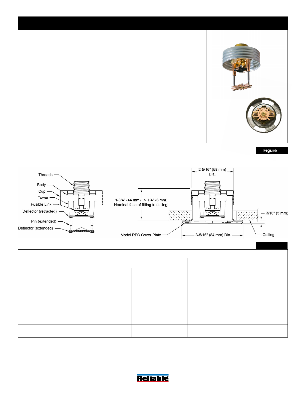
Model RFC43 & RFC43LL Residential Sprinklers
Technical Specifications
Style: Flat Concealed Pendent
Threads: 1/2” NPT or ISO 7-1R1/2
Nominal K-Factor: 4.3 (62 metric)
Max. Working Pressure: 175 psi (12 bar)
Min. Spacing: 8 ft. (2.4 m)
Material Specifications
Thermal Sensor: Nickel Alloy Solder Link
Sprinkler Body: Brass Alloy
Levers: Bronze Alloy
Yoke: Brass Alloy
Sealing Assembly: Nickel Alloy with PTFE
Load Screw: Bronze Alloy
Towers: Copper Alloy
Pins: Stainless Steel
Deflector: Bronze Alloy
Cup: Steel
Cover Plate Finishes
(See Table H)
Sensitivity
Fast-response
Temperature Rating
Ordinary:
165°F (74°C) sprinkler
135°F (57°C) cover plate
Intermediate:
212°F (100°C) sprinkler
165°F (74°C) cover plate
Cover Plate
Model RFC cover plate
Sprinkler Wrench
Model FC (without wrench-able cap)
Model W3 (with wrench-able cap)
Listings and Approvals
cULus Listed to UL 1626
cULus Certified for Health Effects to NSF/ANSI
Standard 61 Annex G (RFC43LL only)
Watermark Certified (RFC43LL only)
RFC43: SINRA0612
RFC43LL: SINRA3212
Bottom View
Model RFC43 & RFC43LL Sprinkler Components and Dimensions
Model RFC43 & RFC43LL Sprinkler Hydraulic Design Criteria
Minimum Flow and Residual Pressure
Max. Coverage Area
(2)
ft. x ft.
(m x m)
15 x 15
(4.6 x 4.6)
16 x 16
(4.9 x 4.9)
18 x 18
(5.5 x 5.5)
20 x 20
(6.1 x 6.1)
Notes:
1. For NFPA 13 installations the flow per sprinkler must be the greater of: (1) the flow listed in Table C above and (2) the flow required to
achieve a minimum design density of 0.1 gpm/sq ft over the design area of the sprinkler.
2. For coverage area dimensions less than those listed above, use the minimum required flow for the next larger max. coverage area listed.
Ordinary Temperature Intermediate Temperature
Flow
gpm
(l/min)
12
(45)
13
(49)
18
(68)
21
(79)
Pressure
psi
(bar)
7.8
(0.54)
9.1
(0.63)
17.5
(1.21)
23.8
(1.64)
(1)
Flow
gpm
(l/min)
12
(45)
13
(49)
-- --
-- --
Figure 2
Table C
Pressure
psi
(bar)
7.8
(0.54)
9.1
(0.63)
Bulletin 006
May 2019
www.reliablesprinkler.com
Page 3 of 8
Page 4

Model RFC49 & RFC49LL Residential Sprinklers
RFC49: SINRA0616
RFC49LL: SINRA3216
Technical Specifications
Style: Flat Concealed Pendent
Threads: 1/2” NPT or ISO 7-1R1/2
Nominal K-Factor: 4.9 (71 metric)
Max. Working Pressure: 175 psi (12 bar)
Min. Spacing: 8 ft. (2.4 m)
Material Specifications
Thermal Sensor: Nickel Alloy Solder Link
Sprinkler Body: Brass Alloy
Levers: Bronze Alloy
Yoke: Brass Alloy
Sealing Assembly: Nickel Alloy with PTFE
Load Screw: Bronze Alloy
Towers: Copper Alloy
Pins: Stainless Steel
Deflector: Bronze Alloy
Cup: Steel
Cover Plate Finishes
(See Table H)
Sensitivity
Fast-response
Temperature Rating
Ordinary:
165°F (74°C) sprinkler
135°F (57°C) cover plate
Intermediate:
212°F (100°C) sprinkler
165°F (74°C) cover plate
Cover Plate
Model RFC cover plate
Sprinkler Wrench
Model FC (without wrench-able cap)
Model W3 (with wrench-able cap)
Listings and Approvals
cULus Listed to UL 1626
cULus Certified for Health Effects to NSF/ANSI
Standard 61 Annex G (RFC49LL only)
Watermark Certified (RFC49LL only)
Model RFC49 & RFC49LL Sprinkler Components and Dimensions
Bottom View
Figure 3
Model RFC49 & RFC49LL Sprinkler Hydraulic Design Criteria
Minimum Flow and Residual Pressure
Max. Coverage Area
(2)
ft. x ft.
(m x m)
16 x 16
(4.9 x 4.9)
18 x 18
(5.5 x 5.5)
20 x 20
(6.1 x 6.1)
Notes:
1. For NFPA 13 installations the flow per sprinkler must be the greater of: (1) the flow listed in Table D above and (2) the flow required to
achieve a minimum design density of 0.1 gpm/sq ft over the design area of the sprinkler.
2. For coverage area dimensions less than those listed above, use the minimum required flow for the next larger max. coverage area listed.
Bulletin 006
May 2019
Ordinary Temperature Intermediate Temperature
Flow
gpm
(l/min)
13
(49.0)
17
(64.3)
20
(75.7)
Pressure
psi
(bar)
7.0
(0.48)
12.0
(0.83)
16.7
(1.15)
(1)
Flow
gpm
(l/min)
13
(49.0)
17
(64.3)
21
(79.5)
www.reliablesprinkler.com
Table D
Pressure
psi
(bar)
7.0
(0.48)
12.0
(0.83)
18.4
(1.27)
Page 4 of 8
Page 5

Model RFC58 Residential Sprinkler SIN RA0613
Technical Specifications
Style: Flat Concealed Pendent
Threads: 1/2” NPT or ISO 7-1R1/2
Nominal K-Factor: 5.8 (84 metric)
Max. Working Pressure: 175 psi (12 bar)
Min. Spacing: 8 ft. (2.4 m)
Material Specifications
Thermal Sensor: Nickel Alloy Solder Link
Sprinkler Body: Brass Alloy
Levers: Bronze Alloy
Yoke: Brass Alloy
Sealing Assembly: Nickel Alloy with PTFE
Load Screw: Bronze Alloy
Towers: Copper Alloy
Pins: Stainless Steel
Deflector: Chrome Plated Bronze Alloy
Cup: Steel
Cover Plate Finishes
(See Table H)
Sensitivity
Fast-response
Temperature Ratings
Ordinary:
165°F (74°C) sprinkler
135°F (57°C) cover plate
Intermediate:
212°F (100°C) sprinkler
165°F (74°C) cover plate
Cover Plate
Model RFC Cover Plate
Sprinkler Wrench
Model FC (without wrench-able cap)
Model W3 (with wrench-able cap)
Listings and Approvals
cULus Listed
Model RFC58 Sprinkler Components and Dimensions
Bottom View
Figure 4
Model RFC58 Sprinkler Hydraulic Design Criteria
Minimum Flow and Residual Pressure
Max. Coverage Area
ft. x ft.
(m x m)
16 x 16
(4.9 x 4.9)
18 x 18
(5.5 x 5.5)
20 x 20
(6.1 x 6.1)
Notes:
1. For NFPA 13 installations the flow per sprinkler must be the greater of: (1) the flow listed in Table E above and (2) the flow required to
achieve a minimum design density of 0.1 gpm/sq ft over the design area of the sprinkler.
2. For coverage area dimensions less than those listed above, use the minimum required flow for the next larger max. coverage area listed.
Bulletin 006
May 2019
(2)
Flow
gpm
(l/min)
16
(60.6)
18
(68.1)
20
(75.7)
( 1)
Pressure
psi
(bar)
7.6
(0.53)
9.6
(0.66)
11.9
(0.82)
www.reliablesprinkler.com
Table E
Page 5 of 8
Page 6

Model RFC76 Residential Sprinkler SIN RA0618
Technical Specifications
Style: Flat Concealed Pendent
Threads: 3/4” NPT or ISO 7-1R3/4
Nominal K-Factor: 7.6 (109 metric)
Max. Working Pressure: 175 psi (12 bar)
Min. Spacing: 8 ft. (2.4 m)
Material Specifications
Thermal Sensor: Nickel Alloy Solder Link
Sprinkler Body: Brass Alloy
Levers: Bronze Alloy
Yoke: Brass Alloy
Sealing Assembly: Nickel Alloy with PTFE
Load Screw: Bronze Alloy
Towers: Copper Alloy
Pins: Stainless Steel
Deflector: Bronze Alloy
Cup: Steel
Cover Plate Finishes
(See Table H)
Sensitivity
Fast-response
Temperature Ratings
Ordinary:
165°F (74°C) sprinkler
135°F (57°C) cover plate
Intermediate:
212°F (100°C) sprinkler
165°F (74°C) cover plate
Cover Plate
Model RFC Cover Plate
Sprinkler Wrench
Model FC (without wrench-able cap)
Model W3 (with wrench-able cap)
Listings and Approvals
cULus Listed
Model RFC76 Sprinkler Components and Dimensions
Bottom View
Figure 5
Model RFC76 Flat Concealed Sprinkler Hydraulic Design Criteria
Minimum Flow and Residual Pressure
Max. Coverage Area
ft. x ft.
(m x m)
16 x 16
(4.9 x 4.9)
18 x 18
(5.5 x 5.5)
20 x 20
(6.1 x 6.1)
Notes:
1. For NFPA 13 installations the flow per sprinkler must be the greater of: (1) the flow listed in Table E above and (2) the flow required to
achieve a minimum design density of 0.1 gpm/sq ft over the design area of the sprinkler.
2. For coverage area dimensions less than those listed above, use the minimum required flow for the next larger max. coverage area listed.
Bulletin 006
May 2019
(2)
Flow
gpm
(l/min)
21
(79.5)
24
(90.8)
34
(128.7)
( 1)
Pressure
psi
(bar)
7.6
(0.52)
9.9
(0.68)
20
(1.4)
www.reliablesprinkler.com
Table E
Page 6 of 8
Page 7

Cover Plate Finishes
(1)
Table H
Standard Finishes Special Application Finishes
White Polyester Off White Paint Black Paint Raw Brass
Chrome Plated Bright Brass Finished Bronze Black Plated
Satin Chrome Stainless Steel Clad
Notes:
1. Paint or any other coating applied over the factory finish will void all approvals and warranties.
2. Custom color paint is semi-gloss, unless specified otherwise.
3. Stainless steel clad cover plates are Type 316 Stainless Steel on the finished side and C102 Copper Allow on the back side. Cover plates
are not listed or approved as corrosion resistant. Stainless steel clad cover plates are not available perforated.
(3)
Custom Color Paint
(2)
Installation Dimensions
Sprinkler
Model
RFC30,
RFC30LL
Cover
Plate
Model
RFC
RFC43,
RFC43LL,
RFC49,
RFC
RFC49LL
Cover Plate
Diameter
inch (mm)
3-5/16
(84)
3-5/16
(84)
Recommended
Hole Diameter
in Ceiling
inch (mm)
2-5/8
(67)
2-5/8
(67)
Cover Plate
Adjustment
inch (mm)
1/2
(13)
1/2
(13)
Min. to
Max. Face
of Fitting to
Ceiling
(1)
inch (mm)
1-1/2 to 2
(38 to 51)
1-1/2 to 2
(38 to 51)
Min. to Max.
Dropped Deflector
Distance below
Ceiling
inch (mm)
1/2 to 1
(13 to 25)
1/2 to 1
(13 to 25)
Table J
Cover Plate
Temperature
Rating
135°F
(57°C)
135°F
(57°C)
or 165°F
(74°C)
135°F
RFC58,
RFC76
RFC
3-5/16
(84)
2-5/8
(67)
3/4
(19)
1-1/2 to 2-1/4
(38 to 57)
1/4 to 1
(6 to 25)
(57°C)
or 165°F
(74°C)
Notes:
1. Face of fitting to ceiling dimensions are based on a nominal thread make up. Verify dimensions based on fitting and thread sealing method
prior to installation. A 1/2” x 1/2” brass nipple extension (Reliable P/N 6999991900) is available where necessary for replacement of existing
sprinklers.
2. For use with 165°F (74°C) temperature rated sprinklers where the Maximum Ceiling Temperature does not exceed 100°F (38°C).
3. For use with 212°F (100°C) temperature rated sprinklers where the Maximum Ceiling Temperature does not exceed 150°F (66°C).
Installation
Model RFC series sprinklers are intended to be installed in accordance with NFPA 13, NFPA 13R, or NFPA 13D, as well as the
requirements of applicable authorities having jurisdiction. Model RFC series sprinklers must not be installed in ceilings with
positive pressure in the space above. Ensure that the 4 slots in
the cup are open and unobstructed following installation. Model
RFC series sprinklers are shipped with a wrench-able protective cap that should remain on the sprinkler until the sprinkler
system is placed in service following construction.
Model RFC series sprinklers can be installed without removing
the wrench-able protective cap using the Model W3 wrench.
Alternatively, Model RFC series sprinklers can be installed using the Model FC wrench by temporarily removing the protective cap during installation of the sprinkler. The use of any other
wrench to installed Model RFC series sprinklers is not permitted and may damage the sprinkler. Fully insert the Model W3
wrench over the cap until it reaches the bottom of the cup, or
the Model FC wrench over the sprinkler until the wrench engages the body. Do not wrench any other part of the sprinkler/cup
assembly. The Model W3 and FC wrenches are designed to be
turned with a standard 1/2” square drive. Tighten the sprinkler
into the fitting after applying a PTFE based thread sealant to the
sprinkler’s threads. Recommended installation torque is 8 to 18
ft-lbs (11 to 24 N-m) for 1/2” thread sprinklers and 14 to 20 ft-lbs
(19 to 27 N-m) for 3/4” thread sprinklers.
Bulletin 006
May 2019
Do not exceed the maximum recommended torque. Exceeding
the maximum recommended torque may cause leakage or impairment of the sprinkler. Use care when inserting or removing
the wrench from the sprinkler to avoid damage to the sprinkler.
Install the cover plate by hand by pushing the cover plate into
the cup and turning the cover in the clockwise direction until it
is tight against the ceiling.
Application
Model RFC series sprinklers are intended for installation where
residential sprinklers are permitted or required by NFPA 13,
NFPA 13R, and NFPA 13D. The sprinklers are concealed pendent residential sprinklers.
Model RFC 30 and RFC30LL sprinklers are available in ordinary
temperature classification for installation where the Maximum
Ceiling Temperature does not exceed 100°F (38°C). Model
RFC43, RFC43LL, RFC49, RFC49LL, RFC58, and RFC76 sprinklers are available in either ordinary or intermediate temperature classification for installation where the Maximum Ceiling
Temperature does not exceed 100°F (38°C) or 150°F (66°C),
respectively.
Page 7 of 8
www.reliablesprinkler.com
(2)
(3)
(2)
(3)
Page 8

Wrench
Model FC
For use with Model RFC Series sprinklers
without wrench-able cap installed
Maintenance
Model RFC series sprinklers should be inspected and the
sprinkler system maintained in accordance with NFPA 25. Do
not clean sprinklers with soap and water, ammonia or any other
cleaning fluids. Remove dust by gentle vacuuming. Replace
any sprinkler cover plate assembly which has been painted
(other than factory applied) or damaged in any way. A stock of
spare sprinklers should be maintained to allow quick replacement of damaged or operated sprinklers. Prior to installation,
sprinklers should be maintained in the original cartons and
packaging until used to minimize the potential for damage to
sprinklers that would cause improper operation or non-operation.
Listings and Approvals
Listed by Underwriters Laboratories, Inc. and UL Certified for
Canada to UL1626, Residential Sprinklers for Fire-protection
Service (cULus).
Certified by Underwriters Laboratories, Inc. and Underwriters Laboratories of Canada for Health Effects to NSF/ANSI
Standard 61 Annex G (LL) (RFC30LL, RFC43LL, and RFC49LL
only).
Australian WaterMark Certified (RFC30LL, RFC43LL, and
RFC49LL only).
Model W3
For use with Model RFC Series sprinklers
with wrench-able cap installed
Guarantee
For the Reliable Automatic Sprinkler Co., Inc. guarantee, terms,
and conditions, visit www.reliablesprinkler.com.
Patents
Model RFC30, RFC30LL, RFC43, RFC43LL, RFC49, RFC49LL,
RFC58, and RFC76 sprinklers are covered by U.S. Patent No.
9,248,327 and U.S. Patent No. 7,275,603.
Model RFC30, RFC30LL, RFC43 and RFC43LL sprinklers are
additionally covered by U.S. Patent No. 8,776,903.
Ordering Information
Specify the following when ordering.
Sprinkler
• Model (RFC30, RFC30LL, RFC43, RFC43LL,
RFC49, RFC49LL, RFC58, RFC76)
• Temperature Rating
Cover Plate
• Model RFC
• Temperature Rating
• Finish (See Table H)
Sprinkler Wrench
• Model FC
• Model W3
Bulletin 006
May 2019
P/N 9999970261
Page 8 of 8
www.reliablesprinkler.com
 Loading...