

Page 1
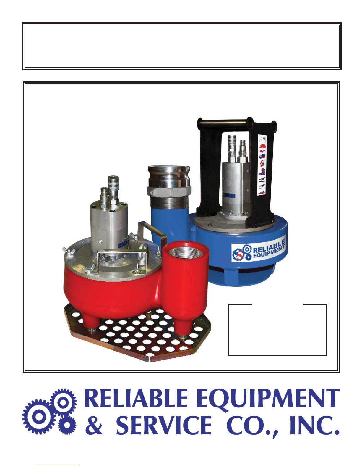
OPERATORS’ GUIDE
REL-TP SERIES
HYDRAULIC TRASH PUMPS
The REL-TP SERIES Trash Pumps
are a light weight, efficient way to
move large quantities of liquids FAST.
REL-TP4
REL-TP3
NOTICE
Sizes, weights and specifi cations
listed in this manual are subject to
change without notice.
Please consult factory for
information and updates.
REL-SP SERIES Manual -1
1
Page 2
DISTRIBUTED BY
THIS SYMBOL INDICATES ITEMS OF EXTREME IMPORTANCE.
Obey all safety messages that follow this symbol to avoid possible injury or
death. Safety of user and others may be in jeopardy if these instructions are
not read and understood.
WARNING
All information found in this guide
must be read and understood
before use or testing of tool.
Failure to read and understand warnings
and safe handling instructions could result
in severe personal injury and or death.
A digital copy of this manual is available
on line at www.Reliable-Equip.com
This Safety Alert and Signal Word indicate a imminently hazardous
situation which if not avoided, will result in death or serious injury.
This Safety Alert and signal word indicate a imminently hazardous
situation which if not avoided, could result in minor or moderate injury.
This Safety Alert and signal word indicate a imminently hazardous
situation which if not avoided, may result in minor or moderate injury.
This Signal word indicate a imminently hazardous situation whic
if not avoided, may result in Property Damge.
This Signal Word indicate a imminently hazardous situation whic if
not avoided, will result in Damage to the Equipment.
This Signal word indicate a imminently hazardous situation whic if
not avoided, may result in Damage to the Equipment.
Always observe these warnings to avoid tool damage, serious injury or death.
The information in this manual is intended to guide the user
in the use and application of this tool. It is not intended as
a substitute for proper training and experience in safe work
practices for this type of equipment.
WARNING
Consult your supervisor or safety personnel if you have any
questions regarding the safe operation of this tool.
2
Page 3

TABLE OF CONTENTS
DISTRIBUTOR INFORMATION ..................................................................2
TABLE OF CONTENTS ...............................................................................3
REGISTRATION ...........................................................................................3
REL-TP3 TOOL SPECIFICATIONS ............................................................4
REL-TP4 TOOL SPECIFICATIONS ............................................................5
PUMP
SAFETY INFORMATION AND WARNINGS ...........................................7-10
HYDRAULIC SYSTEM REQUIREMENTS .................................................11
HYDRAULIC FLUIDS ................................................................................11
OPERATING INSTRUCTIONS ..................................................................12
DAILY MAINTENANCE & LABELS ............................................................13
TROUBLESHOOTING & REPAIR INTRO ..................................................14
OPERATION RECORDS ............................................................................15
VISUAL WARNINGS ...................................................................................16
CONTACT INFORMATION .........................................................................16
PERFORMANCE
...............................................................................6
REGISTRATION
UPON RECEIPT OF THIS TOOL, COMPLETE THE REGISTRATION BELOW.
COMPANY _____________________________________________________________
ADDRESS _____________________________________________________________
________________________________________________________________________
PHONE _______________________ FAX____________________________________
SERIAL NUMBER _______________________________________________________
DATE OF PURCHASE ___________________________________________________
DEALER NAME _________________________________________________________
3
Page 4
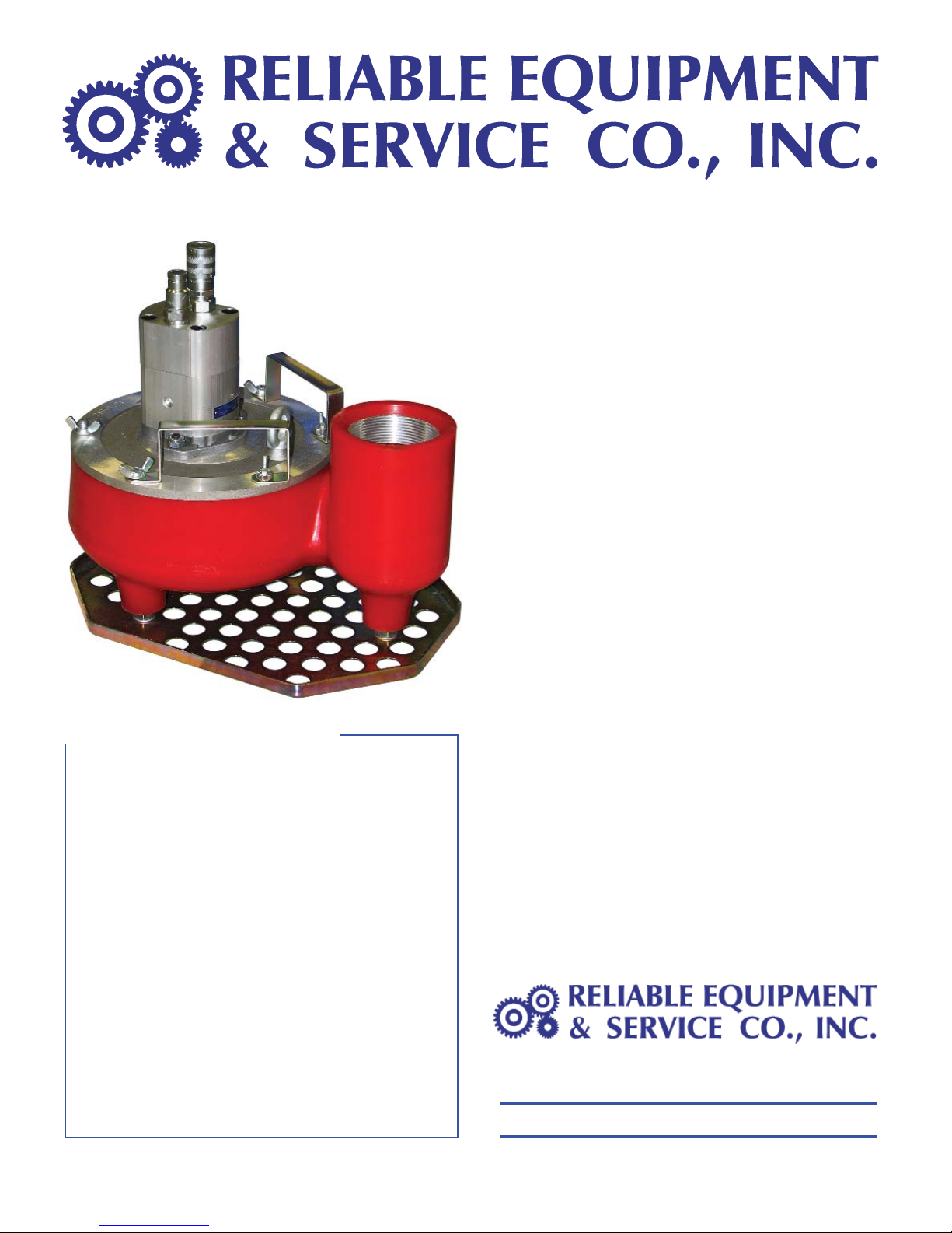
REL-TP3 - 3” Trash Pump
SPECIFICATIONS
Capacity ................ 475 gpm (1,800 lpm)
Discharge Dia. ...... 3 in. (75 mm) Fem Pipe Thd
Inlet Dia. ................ 3 in. (75 mm)
Pressure ............... 2,000 psi (140 bar)
Flow ...................... 7–9 gpm (26–34 lpm)
Porting .................. #10 SAE (pressure)
................................ #12 SAE (return)
Connections ......... 1/2 in. Male Pipe (
................................ 1/2 in. Male Pipe (
Pressure)
Return)
The RELIABLE REL-TP3 Hydraulic Trash Pump
is lightweight, yet capable of moving high volumes
of water, and solids (sand slurries, gravel, and
sludge) up to 3 inches (75 mm) in diameter and
30% by volume.
The REL-TP3 pump is fully submersible, self
priming, and may be run dry, without damage to
the motor, bearings or impeller.These urethane
pumps have a history of pumping sand, gravel,
concrete, and even mortar slurries without issue.
The REL-TP3 is even able to pump petroleum
products without issue.
The urethane bowl and impeller are extremely
durable and light weight. Hard and sharp materials
bounce off instead of abrading the interior surfaces,
making this design last longer and perform better
than aluminum, iron and even steel pumps.
The high volume impeller is complimented by a
3” (75 mm) inlet and outlet to make the REL-TP3
one of the most productive pumps on the market.
This unit is capable of pumping over 450 gpm
(1,688 lpm) at a 10 ft. (2.54 m) head from any
2,000 psi (HTMA
only 9 gpm (34 lpm) of hydraulic flow.
The top cover is attached to the volute with
six large wing nuts making routine cleaning,
inspection and maintenance FAST & EASY.
The convenient Split Handles provides a well
balanced lift.
The REL-TP3 Trash Pump can be paired with the
REL-HPU-2000 Hydraulic Power Unit to make a
Powerful Portable Combo for high volume trash
pump and dewatering applications.
Consult your local Reliable representative for
more “Tooling Solutions” available from
Type ll) hydraulic source using
Reliable Equipment & Service Co., Inc.
Height ................... 13 in. (33 cm)
Length ................... 14 in. (35.5 cm)
Width ..................... 16 in. (41 cm)
Weight ................... 30 lbs (13.6 kg)
301 Ivyland Road • Warminster, PA 18974
Phone: 800-966-3530
Visit us on the web at www.Reliable-Equip.com
• Fax: 215-357-9193
4
Page 5
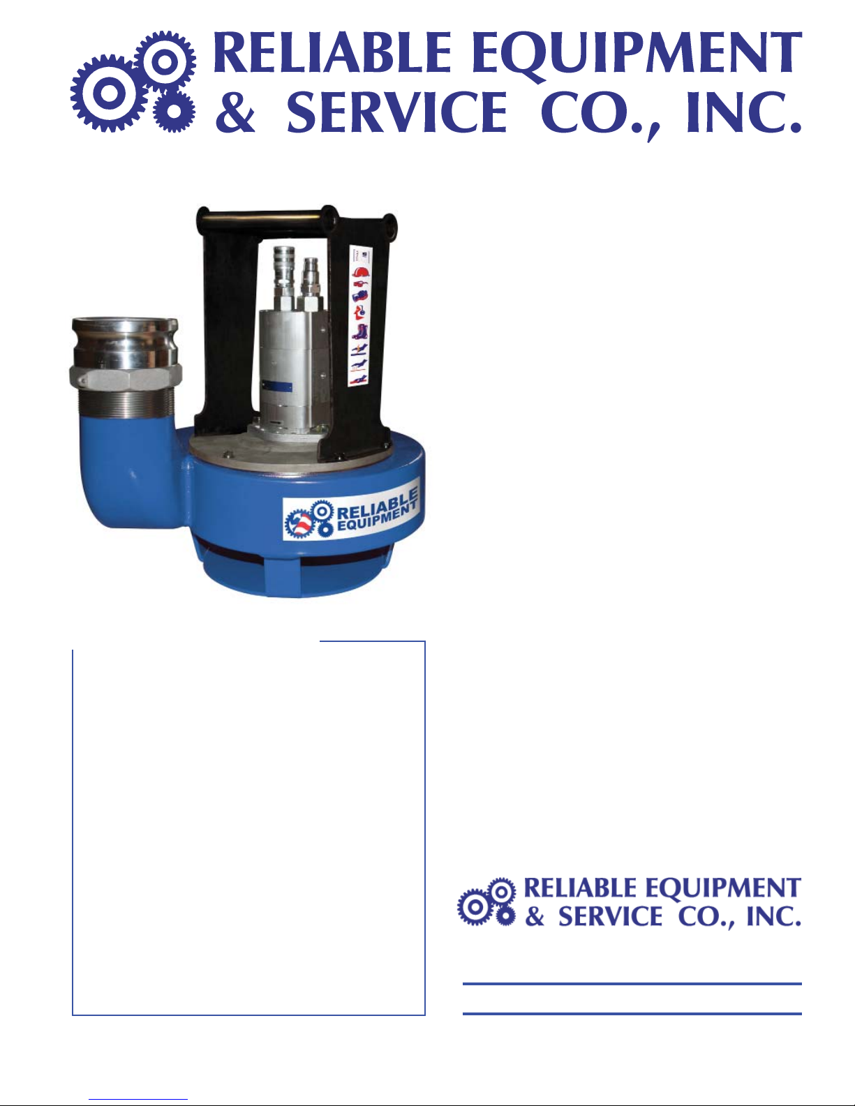
REL-TP4 - 4” Trash Pump
SPECIFICATIONS
Capacity ................ 875 gpm (3312 lpm)
Discharge Dia. ...... 4 in. (100 mm) Cam Lock
The RELIABLE REL-TP4 4 inch, heavy
duty Hydraulic Trash Pump is lightweight, yet
capable of moving high volumes of water, and
solids (sand slurries, gravel, and sludge) up to
3 inches (75 mm) in diameter.
The REL-TP4 pump is fully submersible, self
priming, and may be run dry, without damage
to the motor, bearings or impeller.
The high volume impeller is complimented
by a 4” (100 mm) inlet and outlet to make the
REL-TP4 one of the most productive pumps
on the market. This unit is capable of pumping
over 800 gpm (3,028 lpm) at a 10 ft. (2.54
m) head from any 2,000 psi (HTMA Type ll)
hydraulic source using only 9 gpm (34 lpm) of
hydraulic fl ow.
The top cover is attached to the volute with
six large wing nuts making routine cleaning,
inspection and maintenance FAST & EASY.
The REL-TP4 features a steel volute with
replaceable polyethylene wear plates, a self
lubricating H/D hydraulic motor, and an abrasion
resistant cast iron impeller to extend pump life.
The convenient Split Grip Handle provides
a well balanced lift and protection for the
hydraulic components.
Inlet Dia. ................ 3 in. (75 mm)
Pressure ............... 2,000 psi (140 bar)
Flow ...................... 7–10 gpm (26–38 lpm)
Porting .................. #10 SAE (pressure)
................................ #12 SAE (return)
Connections ......... 1/2 in. Male Pipe (
................................ 1/2 in. Male Pipe (
Height (
Length ................... 19 in. (48.3 cm)
Width ..................... 15 in. (38.1 cm)
Weight ................... 59 lbs (26.8 kg)
w/ handle) .. 19 in. (48.2 cm)
Pressure)
Return)
Pair the REL-TP4 Trash Pump with the
REL-HPU-2000 Hydraulic Power Unit to make
a Powerful Portable Combo for high volume
trash pump and dewatering applications.
Consult your local Reliable representative
for more “Tooling Solutions” available from
Reliable Equipment & Service Co., Inc.
301 Ivyland Road • Warminster, PA 18974
Phone: 800-966-3530
Visit us on the web at www.Reliable-Equip.com
5
• Fax: 215-357-9193
Page 6
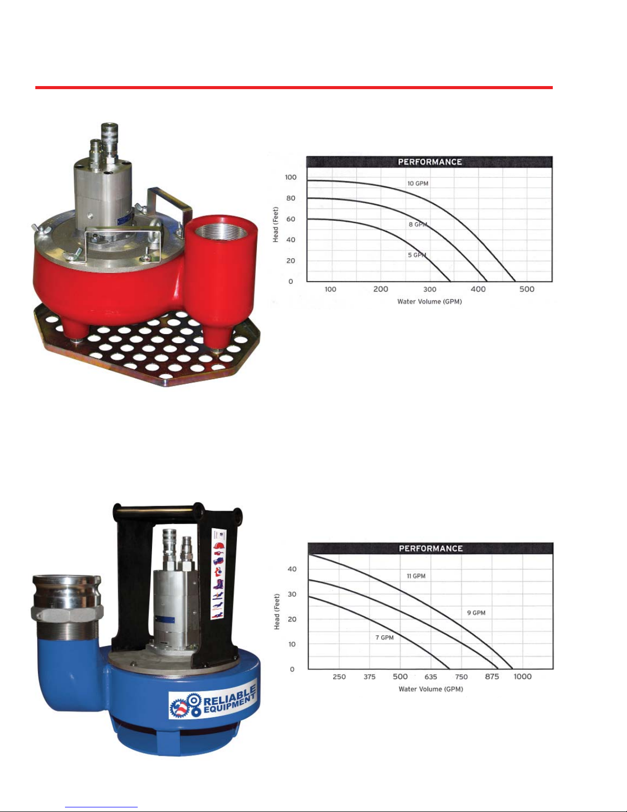
HYDRAULIC TRASH PUMP PERFORMANCE
REL-TP3
3” TRASH PUMP
Testing was done in a controlled environment
with a fi xed discharge assembly using regu-
lated pressures and fl ows.
Results may vary under fi eld conditions.
The warranty becomes void if the maximum
pressures and flows are exceeded.
Backpressure should be measured at the tool
before being used. Excessive backpressure
will damage shaft seal.
REL-TP4
4” TRASH PUMP
Consult your supervisor, safety personnel, or
RELIABLE EQUIPMENT with any questions
regarding the safe operation of this tool.
6
Page 7

BEFORE USING THIS TOOL, READ THE WARNINGS
and the recommended practices described in this manual.
Failure by the operator to read and fully understand these
warnings will leave this person unqualified to use and
operate this tool. Property damage, severe personal injury,
WARNING
These warnings will appear in appropriate locations when they are pertinent to the
particular subject being shown. Read each one carefully and follow them strictly.
and/or death could result by not following these warnings.
Eye
Protection
WARNING
Always wear eye protection to avoid
injury from flying debris or hydraulic
oil leaks. Failure to do so can result in
serious personal injury.
Hard Hat
WARNING
Always wear a hard hat to avoid injury
from falling debris. Failure to do so can
result in serious personal injury.
Skin
Irritation
WARNING
Hydraulic oil may cause irritation.
Use care to prevent contact with skin.
In case of accidental contact, wash
affected area immediately
Foot
Protection
WARNING
Always wear foot protection.
Failure to do so can result in serious
personal injury.
Hearing
Protection
WARNING
Always wear hearing protection,
to avoid hearing loss due to long
term exposure to high noise levels.
Protective
Gloves
WARNING
Always wear protective gloves & cloths.
Failure to do so can result in serious
personal injury.
7
Page 8

SAFE OPERATION & CARE
USE THIS TOOL FOR ITS INTENDED PURPOSE ONLY
Any other use can result in injury or property damage.
WARNING
WARNING
INSPECT TOOL BEFORE USE. Replace any worn, damaged
or missing parts. A damaged or improperly assembled tool may
malfunction, injuring operator and/or nearby personnel.
INSPECT HYDRAULIC HOSES AND COUPLINGS before each
use. Repair or replace if any cracking, leakage, wear or damage is
found. Worn or damaged hoses may fail resulting in personal injury
or property damage.
CLEAR WORK AREA of all bystanders and unnecessary personnel
before operating this tool.
KEEP ALL PARTS OF THE BODY AWAY FROM MOVING P ARTS.
Failure to observe this warning could result in serious injury.
HYDRAULIC POWER SUPPLY
TURN HYDRAULIC SOURCE OFF before making any connection
DO NOT attempt to make any changes to any of the component
parts or accessories when connected to the power source.
DO NOT adjust, inspect, or clean any tool while the tool is connected
to the power source. The tool could accidentally start up and cause
serious injury.
DO NOT lock the tool in the On Position. In an emergency, serious
damage or injury could occur during the time required to stop the tool.
Hydraulic oil or fl uid under the skin is a serious injury. Oil under
pressure can penetrate the skin and may cause dismemberment
or loss of life. Seek medical assistance immediately if such an
DANGER
injury should occur.
Always wear safety gloves, eye protection and all required safety
equipment when operating or handling this tool.
DO NOT use fingers or hands to attempt to locate a leak.
DO NOT handle hoses or couplers while system is pressurized.
NEVER open or service the system before depressurizing.
OIL INJECTION INJURY
8
Page 9

HOSES AND FITTINGS
There exists the potential for shock in using anything other than
certifi ed non-conductive hoses and hydraulic oil with dielectric
properties, when using system components near energized electrical
WARNING
Hoses and fittings used with this tool must comply with S.A.E. J1273 which
covers recommended practice for selection, installation, and maintenance of hose and
hose assemblies. The correct hoses and fi ttings are available from your supplier.
WARNING: Failure to comply with these warnings could result in severe bodily injury or death.
lines. Failure to recognize these conditions could cause electrocution.
UNIT/HOSE CONNECTIONS
ALWA YS DISCONNECT pump/power source and turn the key to the
OFF position before connecting or disconnecting any components.
WARNING
WARNING
ALWAYS DEPRESSURIZE hydraulic system, before connecting
or disconnecting any of the systems components.
ALWAYS TIGHTEN COUPLINGS COMPLETELY. Loose or
improperly connected couplings may not allow fl uid to pass through
the hose creating a blockage in the supply or return line.
ALW AYS INSPECT HOSES AND CONNECT ORS before connection
to tool. Replace or repair if any leakage is evident. Leakage is a sign
of deterioration in component parts.
Connect hoses and confi rm proper fl ow direction to & from tool.
SERIOUS BURN HAZARD
HOT SURFACES MAY CAUSE SERIOUS BURN INJURY
The hydraulic motor may be hot during and after operation.
CAUTION: HYDRAULIC FLUID MAY CAUSE SERIOUS BURNS
Never disconnect tool, hoses, or fi ttings while the hydraulic power
source is running or if the hydraulic fl uid is hot.
IF YOU HAVE ANY QUESTIONS REGARDING THE SAFE USE
AND/OR OPERATION OF THIS TOOL, CONSULT YOUR AREA SUPERVISOR,
OR CONTACT RELIABLE EQUIPMENT AT 800-966-3530
9
Page 10

ELECTRICAL SHOCK HAZARD
Always wear and use the necessary clothing, equipment and
safety practices to protect against electrical shock. Failure to
WARNING
follow these rules can result in serious personal injury or death.
GENERAL SAFETY
USE ALL APPROPRIA TE AND APPLICABLE PERSONAL SAFETY EQUIPMENT
as required by the operating company.
ALWAYS INSPECT TOOL for wear or deterioration or damage every day.
Worn or damaged parts may cause malfunction of tool or unsafe circumstance.
KEEP ALL BODY PARTS AWAY FROM MOVING PARTS OF THE PUMP.
DO NOT DIRECT DISCHARGE TOWARDS ANY PERSON, ANIMAL OR VEHICLE.
MOVE OUTSIDE DANGER ZONES BEFORE ACTIVATING THE PUMP
MAKE SURE THERE IS NO PERSON IN CLOSE PROXIMITY to you, the
tool, or the discharge who could be injured by any operation being performed,
tool malfunction or flying debris.
DO NOT OVEREXTEND your position by overreaching or unbalancing the footing
necessary to maintain physical control of your body.
USE THIS TOOL FOR THE MANUF ACTURERS’ INTENDED PURPOSE ONL Y.
OBSERVE CLOSEL Y ALL SAFETY RULES FOR A P ARTICULAR JOB CLASS
Operation/Safety methods may vary in accordance with the
working guidelines established by each utility or contractor.
For your own safety, ensure that you fully comply with
all safe operation guidelines required by your employer.
WARNING
Consult your training or safety personnel or supervisor as needed.
10
Page 11

HYDRAULIC SYSTEM REQUIREMENTS
Operating Pressure: 1200-2000 PSI (70-140 bar)
Max. Relief Setting: 2100 psi (145 bar)
Flow Range: 5-9 gpm REL-TP3 7-10 gpm (26-45 lpm) REL-TP4
Max. Backpressure: 250 psi
(17 bar)
Cooling System: Required
Min. Filtration: 25 Micron
Sound Pressure <85 dBA @ 1m
Hydraulic Fluids:
or listed HTMA specifications may be used for this tool.
All hydraulic fluids that meet these listed specifications
S. U. S.
@ 100
@ 210
FLASH POINT ..................... 340
POUR POINT .......................... -30
O
F (38O C) ...........................................140 TO 225
O
F (99O C) ....................................... 40 minimum
O
F min. (170
O
F min. (-34
O
C min.)
O
C min.)
Hydraulic Hoses: 2500 psi (175 bar) minimum working pressure (Ref. J517)
Hose assembly should include fl ush face quick disconnect
couplers as recommended by the HTMA.
(Hydraulic Tool Manufacturers Association)
CAPACITY
Intake Port: 3 in. (75mm) 3 in. (100 mm)
Discharge Port: 3” NPFT (75mm) 4” NPT (100 mm)
Discharge Capacity: Up to 450 gpm Up to 875 gpm (3,312 lpm)
(Illustration pg 6) (Illustration pg 6)
WEIGHT & CLEARANCE
Weight: 30 lbs. 60 lbs. (9.5 kg)
Height: 13” (over handle) 19 in. (over handle)
Width: 14” L x 12” W 19” L x 15” W
Operation/Safety methods may vary in accordance with the
working guidelines established by each utility or contractor.
For your own safety, ensure that you fully comply with
all safe operation guidelines required by your employer.
WARNING
Consult your training or safety personnel or supervisor as needed.
11
Page 12

OPERATION
PRE-OPERATION
Do not use this tool under unsafe working conditions or locations.
Use this pump only for it’s intended purpose.
This pump is not designed for operation with a suction pipe inlet.
Read entire manual prior to operation of this tool.
(Refer to all safety recommendations and warnings)
Observe all safety precautions & procedures required by the operating company .
Check the Pump inlet screen and discharge for debris or obstruction.
Connect a compatible discharge hose and securely tighten.
Ensure that hydraulic source is OFF and Control V alve is in the OFF position
before making any connections.
Connect appropriate hydraulic hose to the tools’ return and pressure ports.
(Length may vary) Use a length of hose that will not restrict free movement, or
pose any hazard to the operator or other personnel on the work site.
OPERATION
Observe ALL required safety guidelines established by the Utility or Contractor.
Lower the pump into the liquid, or position tool as required by the application.
Remove any kinks from discharge hose to ensure proper fl ow of discharge.
Position and direct the discharge hose in a manner that neither hose, or discharge
will restrict free movement, or pose a hazard to the operator or other personnel.
WARNING DO NOT direct discharge towards any person, animal or vehicle.
T urn ON hydraulic source and select an appropriate fl ow for the tool. (7 gpm)
COLDER WEA THER
NOTE: Do Not lift water with solids beyond 40 ft. if hydraulic flow is below 7
Move the Control Valve to the ON position.
Allow unit to run, watching for excessive solids and/or reduced discharge fl ow.
Possible Cause: The hydraulic fl ow
The pump may have settled into excessive solids beneath the liquid to be pumped.
Stop Pump to check & resolve.
Reduced fl ow may cause accumulation of solids in the volute, and increase pump wear.
- Allow hydraulic fl uid to warm for 3-5 minutes before operating.
gpm
/ head ratio may be insuffi cient to carry excess solids.
Failure to resolve may result in reduced discharge capacity and/or pump damage.
Move the Control Valve to the OFF position.
Return the Flow Selector to the OFF position, and T urn KEY to the OFF position.
12
Page 13

DAILY MAINTENANCE
IMPORTANT: The greatest cause of hydraulic system failure is dirt.
Prevent the introduction of foreign matter into the pump via hydraulic fl uid,
dirty connections or accumulation of sediment in the hydraulic system.
The life, reliability, and safety of the tool is dependent on proper maintenance.
Maintenance must be performed by authorized and trained personnel ONLY.
Inspect pump for wear or damage. Worn or damaged parts may malfunction during operation.
All parts must be replaced with new parts if signs of wear or damage are evident.
Inspect the fittings, and hydraulic lines. (i.e. kinks, leaks, dirt, etc.) Do Not use hands!
Inspect Hoses. Worn or damaged and aged hoses may malfunction during operation.
Clean and inspect pump before storage. Solids, fi bers and sand may become attached
to the volute, or trapped within the pump chamber and hose assembly.
Remove the volute by removing the six (6) wing nuts (TP3) connecting the cover to the volute.
Lift the entire assembly straight up, from the volute.
CAUTION: Impeller may be sharp.
Clean the inner screen, discharge and the impeller. Impeller removal should not be necessary.
Visually Inspect the impeller for cracks, breakage, and excessive wear. Replace as required.
NOTE: A worn or damaged impeller may reduce pump performance.
If required the impeller may be removed by removing the center cap screw and lockwasher
while holding the impeller. CAUTION: Impeller may be sharp.
Install or replace the impeller using the center cap screw and lockwasher.
Re-assemble the pump by replacing motor/fl ange assembly and securing the handle,
fl ange and volute.
Clean and empty the discharge hose before storage.
Inspect and clean hydraulic couplers before and after each use.
NOTE: Keep Label Set clean and legible. Replace decals when necessary.
BEFORE USING THIS PRODUCT
READ THE SAFETY WARNINGS
and recommended practices described
in the manual. Failure by the operator to
read and fully understand the warnings
will leave this person unqualifi ed to use
CAUTION
Failure to observe all warnings and instructions could result
in property damage, severe personal injury, and/or death.
and operate the tool.
REL-SM
13
Page 14

EXTREME CAUTION SHOULD BE TAKEN TO ENSURE THE SAFETY OF ALL PERSONNEL
Any attempt to resolve a performance related issue, or to repair a product that is not working
as expected in the field, will require knowledge of the tool and the application being performed.
TROUBLESHOOTING TIPS AND FIELD SOLUTIONS
No Hydraulic Flow or Pressure Check Hydraulic Supply - Pressure and Flow
Pump
Will Not
Start
Improper or Defective Coupling Check Coupler Connections and Flow Direction
Insuffi cient Hydraulic Flow Check Flow / Head (refer to illustration on pg. 5)
Volute Screen may be Obstructed. Clear Screen
Performance
Replace Impeller as Required.
Moves Freely by Turning the Center Cap Screw.
Clean
Flow Reversed Check Coupler Connections and Flow Direction
Poor Discharge Kinked or Restricted Straighten Discharge Hose & Clear Obstructions
Impeller Jammed
Volute Screen Restricted
Impeller Worn or Damaged
Disconnect from Source - Ensure that Impeller
/ Clear as required.
Pump may have settled into solids. Raise Pump
Check Impeller for Damage or Excessive Wear
Pump Not Matched to Application Check Requirements - Adjust or Replace Pump.
Excessive Solids in Liquid Reduce Solids
Increasing Flow May Remove Excess Solids,
but may result in wear or damage to the pump.
IF THE ISSUE OR THE PROPER SOLUTION IS NOT FOUND ABOVE
CONTACT YOUR RELIABLE SERVICE REPRESENTATIVE
WARNING: ALL tool repair and service must be performed by authorized
and trained personnel ONLY. Improper maintenance or tampering could
result in malfunction causing damage to equipment and/or injury to personnel.
Complete disassembly is not recommended. Return the unit to an authorized
dealer for total disassembly and/or repair.
All maintenance or disassembly should take place on a fl at, clean work surface
covered with towels or wipers so as to have a clean space for the disassembled parts.
Inspect each part during disassembly for wear, scratches, and cuts. Discard the
worn or damaged parts and replace with new factory authorized parts.
O-rings are sensitive to sharp edges. Inspect closely for cuts or damage. A small
cut will cause a leak. When assembling or disassembling O-rings, use hydraulic
fl uid as a lubricant to help disassembly or installation.
14
Page 15

REL-TP3
HYDRAULIC
SUBMERSIBLE
TRASH PUMP
REL-TP3
PARTS LIST
# P/N Description Qty
1 TP305 Urethane Volute 1
2 TP307 Base 1
3 TP306 Urethane Impeller 1
4 TP321 Gasket 1
5 TP317 Motor Mount Plate 1
6 TP304 Motor 1
7 FF-370 FF Coupler Set 1
8 TP319 Carry Handles 2
9 TP301 Wing Nut 6
10 TP318 Cam Loc 3” Male 1
11 TP315 Motor Mounting Nuts 2
12 TP303 Lifting Eye 1
13 TP314 Motor Mounting Bolts 2
14 TP311 Impeller Washer 1
15 TP310 Impeller Lock Washer 1
16 TP309 Impeller Bolt 1
17 TP312 Base Mounting Nuts 3
18 TP322 Base Mounting Washer 3
19 TP313 Base Mounting Bolts 3
20 TP302 Stud 6
TP316 Shaft Key (NOT SHOWN) 1
TP364 Seal Kit
TP365 Decal Kit
15
Page 16

REL-TP4
HYDRAULIC
SUBMERSIBLE
TRASH PUMP
REL-TP4
PARTS LIST
# P/N Description Qty
1 TP401 Volute 1
2 TP402 Impeller 1
3 TP403 Motor Assembly 1
4 TP404 Woodruff Key 1
5 TP405 Washer 1
6 TP406 Impeller Nut 1
7 TP407 Motor Plate 1
8 TP408 Plate Bolt 6
9 TP409 Plate / Shoe Washer 14
10 TP410 Plate / Shoe Lock Washer 14
11 TP411 UHMW Wear Plate 1
12 TP412 Wear Plate Screws 6
13 TP413 Wear Plate Nuts 6
14 TP414 Shoe 1
15 TP415 Shoe Bolts 8
16 TP417 4” Cam Loc 1
17 TP418 Carry Handle 1
18 TP420 Shim .020 1
19 TP421 Shim .040 1
20 TP422 Shim .080 1
21 FF-370 FF Coupler Set 1
22 TP314 Motor Mount Bolts 2
23 TP315 Motor Mount Nuts 2
24 TP423 In Adapter 1
25 TP424 Out Adapter 1
TP419 Seal Kit
TP425 Decal Kit
16
Page 17

OPERATION RECORDS
Date Hours Liquid Type Solid Type & Concentration Flow Head
17
Page 18

USER NOTES
Read Manual
Protective Head Wear
Protective Eye Wear
Protective Clothing
If you have any questions regarding the information in
this manual please contact RELIABLE EQUIPMENT
at the address, phone or fax numbers shown below.
301 Ivyland Road • Warminster, PA 18974
Phone: 800-966-3530 • Fax: 215-357-9193
Visit us on the web at www.Reliable-Equip.com
Hearing Protection
Protective Foot Wear
Electrical Shock
Hot Surfaces
Hydraulic Injection
18
 Loading...