

Page 1
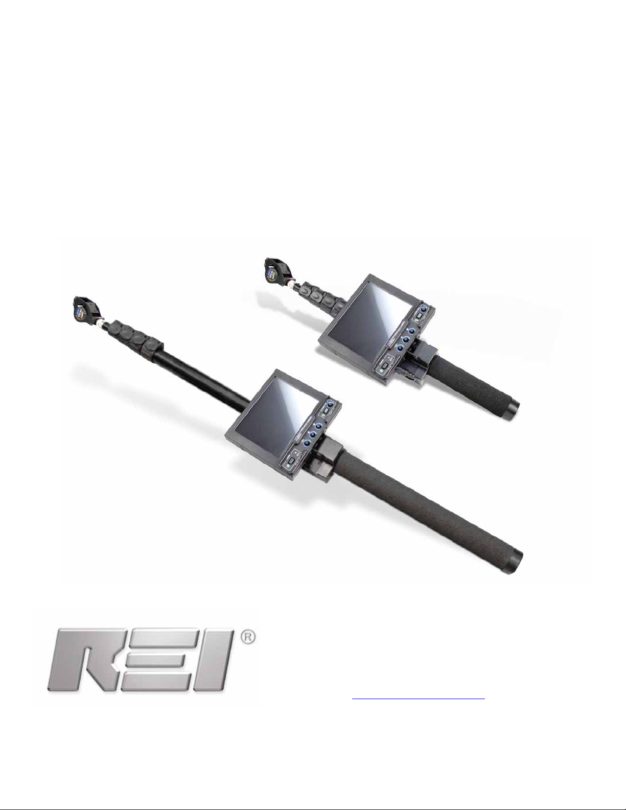
VPC-64/ VPX-64
VIDEO POLE CAMERA
OPERATION MANUAL
RESEARCH ELECTRONICS INTERNATIONAL
455 Security Place
Algood, TN 38506 U.S.A.
+1 931-537-6032
http://www.reiusa.net/
Page 2

© COPYRIGHT RESEARCH ELECTRONICS INTERNATIONAL
This manual contains proprietary information intended solely for use with the VPC-64
Video Pole Camera, and the VPX-64 Extended Pole Camera and relative accessories.
All information contained within this manual is subject to change without notice.
The Video Pole Camera is sold in two different versions:
1. The VPX-64, which extends to 12.5 feet (386cm)
2. The VPC-64, which extends to 6.5 feet (200cm)
This manual covers both units, and instructions and accessories may vary
slightly depending on which model has been purchased.
OWNER’S RECORD
The Serial Number of your unit is located on the side panel. Please record this
number and refer to it whenever you contact your dealer or Research Electronics
International concerning this product. Note: Removal or alteration of the serial
number automatically voids all warranties of this product.
MODEL: VPC-64, or
VPX-64
SERIAL NUMBER: __________________
RESEARCH ELECTRONICS INTERNATIONAL
455 Security Place
Algood, TN 38506 U.S.A.
+1 931-537-6032
http://www.reiusa.net/
Page 3

TABLE OF CONTENTS
TABLE OF CONTENTS
INTRODUCTION........................................................................................ 1
PRECAUTIONS........................................................................................... 3
CONTROLS ............................................................................................... 4
MONITOR.............................................................................................. 4
CAMERA HEAD....................................................................................... 5
USING THE VPC-64 ................................................................................... 6
Assembling the Unit ................................................................................. 6
Operating the Monitor............................................................................. 6
Adjusting the Camera .............................................................................. 6
Extending the Pole ................................................................................... 7
Recording Video ...................................................................................... 7
Viewing Recorded Video........................................................................... 8
Using the Flexible Extension...................................................................... 8
SPECIFICATIONS........................................................................................ 9
PACKING LIST .......................................................................................... 11
i REI VPC/VPX
Page 4

Page 5

INTRODUCTION
INTRODUCTION
Thank you for purchasing the VPC-64 Video Pole Camera, or VPX-64 Extended
Video Pole Camera. Both models of the Video Pole Camera allow you to extend your
view of your surroundings that might otherwise be difficult or dangerous. With REI’s
Video Pole Camera, you can look up into drop ceilings or down underneath desk
and chairs, or other higher to reach areas. In this way you can visually verify
problems without the need to climb ladders or crawl on the floor.
The Video Pole Camera comes standard with a color camera with white LED lights.
This would be suitable for most situations. However, an IR camera with IR lights is
available for times when the white light might be a distraction.
This instruction manual covers the operation and specifications of the VPC-64 Video
Pole Camera and the VPX-64 Extended Video Pole Camera. Operation and
specifications may vary slightly depending the model.
1 REI VPC/VPX
Page 6

Page 7

PRECAUTIONS
PRECAUTIONS
Do not use the Video Pole Camera near power lines or high voltage wiring, possible
electrocution may occur.
Exercise care in walking, climbing or other movements while watching the LCD
Monitor. Serious injuries may result.
If the Video Pole Camera is used to move overhead objects, do not stand directly
under the object or in its path. If the object slips and falls personal injury could
result.
Do not lift objects over 5 lbs with the Video Pole Camera. Damage to the Video Pole
Camera and personal injury could result.
Do not subject the Video Pole Camera to high forces. Damage to the Video Pole
Camera could result.
Use only REI approved Power Supply and Charger to Charge the Battery Packs.
The Video Pole Camera is not waterproof. Do not use the Video Pole Camera under
water. Do not use the Video Pole Camera in conditions that may expose the
components to excessive moisture or water. The electronic circuits can be damage by
excessive moisture.
Do not use the Video Pole Camera in an explosive environment.
3 REI VPC/VPX
Page 8

CONTROLS
MONITOR
CONTROLS
Figure 1 “Monitor Controls”
1. Power On Indicator: The unit can be “ON” with or without a Camera Head
attached to the pole.
2. Power Switch: turns the unit “ON” and “OFF”.
3. DC Power In Jack: power input for the unit.
4. Low Battery Indicator: indicates the battery is low and should be recharged.
5. Color Saturation*: controls the amount of color displayed on the Monitor*.
6. Contrast*: controls the video Monitor contrast.
7. Monitor Brightness*: controls Monitor brightness.
8. Illumination On Indicator: indicates the camera illuminators are turned on.
9. Video In/Out Jack: can be used to send the video signal to an external device,
OR to receive an external video signal for display on the LCD monitor.
10. Illumination Switch: turns the LED Illumination on and off.
11. Illumination Brightness: adjusts the brightness of the Camera Head LED’s.
* These controls only affect the displayed video and not the video image signal from
the Camera Head.
REI VPC/VPX 4
Page 9

CAMERA HEAD
CONTROLS
Figure 2 “Camera Head” (Color Camera Head Pictured)
1. Camera Connector: connects the Camera Head to the pole. This connector
provides both electrical and physical connections.
2. Camera Lens: can be rotated to focus the video image. It can also be changed
with either of the additionally supplied Wide and Telephoto lenses.
3. LED Lights: provide the supplemental light (either white light or IR light,
depending on Camera Head) in low to dark lighting conditions.
4. Rubber Push Pads: can be used to push objects, for example, the Video Pole
Camera could push a drop ceiling tile up to get a view of the upper portion of a
room without needing a ladder. Caution, do not push over 5 lbs with the Video
Pole Camera, damage to the Video Pole Camera or personal injury could result.
5. Tilt Pin: used to rotate the camera to the desired view angle.
5 REI VPC/VPX
Page 10

USING THE VIDEO POLE CAMERA
USING THE VIDEO POLE CAMERA
ASSEMBLING THE UNIT
1. Remove the main body of the Video Pole Camera, which includes the pole and
monitor, from the case.
2. Remove the camera from the case
3. Place the camera on the pole such that two connectors align. There is a tab in
the connector on the pole and a slot in the connector on the camera.
4. Push and rotate the locking ring, located on the camera’s connector.
5. Place a battery pack in the battery holder with the cable away from the pole and
towards the foam grip.
6. Plug the battery connector into the DC Power IN Jack.
OPERATING THE MONITOR
1. Turn the monitor on by pressing the Power Switch.
2. Remove the lens cap from the camera.
3. Adjust the color saturation, contrast and brightness to obtain a desired video
image.
4. The monitor may be tilted and rotated as needed to allow better viewing of the
video image.
5. If desired or in low light conditions the LED illumination can be turned on. To turn
the LED illumination on press the Illumination Switch. The illumination brightness
may be adjusted by the Illumination Brightness control.
ADJUSTING THE CAMERA
The camera may be manually tilted using the outer pins on the camera body. The
camera can be tilted +90 degrees to -25 degrees.
Because the Video Pole Camera can be used in many different conditions the
camera may require focusing. Focusing is a manually adjustment. To focus the
camera, rotate the lens by grabbing the outer ring of the lens. Avoid touching the
clear part of the lens.
In addition to the lens that is shipped on the camera, other lenses are supplied. To
switch lenses, unscrew the lens on the camera. Then screw the new lens on the
camera. Take care to keep any dust or foreign objects out of the camera while the
lens is off. The camera should have a lens installed at all times, including during
non-use periods.
REI VPC/VPX 6
Page 11

USING THE VIDEO POLE CAMERA
EXTENDING THE POLE
The VPC-64 can be extended up to 6.5 feet (200cm) and the VPX-64 can be
extended up to 12.5 feet (386cm). To extend the pole, release one or more locking
latches on the side of the pole. Extend the pole to the desired length. Close the
locking latches. When the Video Pole Camera is at or near its full extended length,
the pole may have to be held at the desired length while the locking latches are
closed.
To retract the pole, open the locking latches and slide the pole sections to the desired
length. Do not force the pole sections. The sections should retract with little force.
The Video Pole Camera contains an internal, high stretch ratio, retractable cord
eliminating any external wires or cables. The retractable cord will naturally pull the
pole sections toward the closed position.
NOTE: If the Video Pole Camera is used with the pole extended near its maximum
length for more than 30 minutes, the tractable cord inside the pole may develop a
memory and retract slower than usual causing part of the cord to be ejected from the
bottom of the pole. In extreme cases, the cord can bind inside the pole. To avoid
potential problems with the retractable cord when the pole has been extended for
long periods of time, collapse the pole slowly, giving the retractable cord time to
retract back to its original stretch ratio memory.
RECORDING VIDEO
The Video Pole Camera is supplied with one external video cable and a Y-adapter.
The cable is used to allow recording or viewing video. An external video recorder
(not supplied) is needed to record video. To record video, insert the 3.5mm stereo
plug in the Video I/O Jack. Then insert the Video Out RCA connector in the video in
of the external video recorder. Under this configuration the LCD monitor will not
display any video. The VPC does not support the recording of audio.
By using the supplied Y-adapter the LCD monitor can display the same video images
that are being recorded. To record video and view the video images on the LCD
Monitor, insert the 3.5mm stereo plug in the Video I/O Jack. Then insert the Video
Out RCA connector in the Y-adapter. Connect the Video In of the cable to the YAdapter. Finally, connect the Y-adapter to the video in of the external video recorder.
7 REI VPC/VPX
Page 12

USING THE VIDEO POLE CAMERA
VIEWING RECORDED VIDEO
Video from an external video source can be viewed on the LCD Monitor of the VPC.
Using the supplied video cable, insert the 3.5mm stereo plug in the Video I/O Jack.
Then the Video In RCA jack in the external video source. Note, when used to view
external video signals the Camera’s video signal is not displayed.
USING THE FLEXIBLE EXTENSION (VPC-64 ONLY)
In some situation, especially small hard-to-reach places, the standard straight, rigid
pole may not adequate. For these situations the flexible extension may help.
The Flexible Extension is placed between the end of the pole and the camera. It
mounts to the camera and the pole in the same fashion as the camera mounts to the
pole. Once attached, the Flexible Extension will allow the camera to be twisted and
rotated in addition to the other adjustment previously mentioned.
Do not use the camera to twist the Flexible Extension, grab the thicker portion of the
Flexible Extension, near the camera. The Flexible Extension is not intended to rotate
360 degrees. Excessive force on the Flexible Extension could result in damage to the
Video Pole Camera. While using the Flexible Extension do not attempt to push any
object with the camera.
REI VPC/VPX 8
Page 13

SPECIFICATIONS
VPC-64
OVERALL LENGTH
Extended with Camera Head attached 6.5 feet (200cm)
Retracted with Camera Head attached 24.5 inches (62cm)
WEIGHT
VPC-64 with Camera Head attached: 3.6 lbs (1.6 kg)
Case with VPC-64 and all accessories: 11.0 lbs (5 kg)
CASE SIZE
18.5 in (47cm) x 6 in (15.3cm) x 14.5 in (36.8cm)
VPX-64
OVERALL LENGTH
Extended with Camera Head attached 12.5 feet (386cm)
Retracted with Camera Head attached 38.0 inches (96cm)
WEIGHT
VPX-64 with Camera Head attached: 4.5 lbs (2.0 kg)
Case with VPC-64 and all accessories: 13.0 lbs (6 kg)
CASE SIZE
36 in (92cm) x 5 in (13cm) x 13 in (33cm)
COLOR LCD DISPLAY
Size: 6.4 inch (16cm) diagonal
Brightness: 300 Nits
Viewing Angles: +/- 50˚ horizontal, +/- 40˚vertical
Display Controls: color saturation, contrast, and brightness
Camera Head Controls: variable illumination
Display Rotation: 80˚ CCW, 180˚ CW
Display Tilt: 0˚ to 90˚
Video In: NTSC/PAL 1Vp-p
Video Out: NTSC 1Vp-p
SPECIFICATIONS
9 REI VPC/VPX
Page 14

SPECIFICATIONS
COLOR CAMERA HEAD*
Signal Format: NTSC
Horizontal Resolution: More than 380 Lines
Sensitivity: 0.5 Lux / F1.2, 1.0 Lux / F2.0 (AGC on)
Illumination: 4 White LEDs with variable brightness control
Camera Lens: 3.6mm, 8 mm, & 16 mm
Camera Tilt: +90˚ to -25˚
IR ILLUMINATED BLACK & WHITE CAMERA HEAD*
Signal Format: NTSC
Horizontal Resolution: 420 Lines
Sensitivity: 0.0003 Lux / F1.2, 1.0 Lux / F2.0 (AGC on)
Illumination: 6 White LEDs with variable brightness control
Camera Lens: 3.6mm, 8 mm, & 16 mm
Camera Tilt: +90˚ to -25˚
* Video Pole Camera’s are sold with various camera configurations; your unit may
not contain both cameras. Additional Camera Heads may be purchased separately.
POWER SUPPLY
9.6 VDC, 2300 mAh, Rechargeable
Average Run-Time: 2.0 hours
Average Battery Charge-Time: 1.8 hours
Maximum input Voltage: 15 VDC
DO NOT USE ANY OTHER BATTERY, CHARGER, OR POWER SUPPLY. USE ONLY
REI SUPPLIED BATTERIES AND CHARGER.
REI VPC/VPX 10
Page 15

VPC-64 PACKING LIST
VPC-64 PACKING LIST
1. Additional Lens (8mm & 16mm)
2. Additional IR Camera (optional)
3. Accessory Compartment
4. Flexible Camera Extension
5. Pole and Monitor
6. Power Supply w/ AC adapter
7. Battery Compartment
8. Battery Charger
9. Video Cables
10. AC Adapter
11. Camera
11 REI VPC/VPX
Page 16

Page 17

VPX-64 PACKING LIST
VPX-64 PACKING LIST
12. Additional Lens (8mm & 16mm)
13. Additional IR Camera (optional)
14. Accessory Compartment
15. Flexible Camera Extension
16. Pole and Monitor
17. Power Supply w/ AC adapter
18. Battery Compartment
19. Battery Charger
20. Video Cables
21. AC Adapter
22. Camera
13 REI VPC/VPX
Page 18

© COPYRIGHT RESEARCH ELECTRONICS INTERNATIONAL
This manual contains Proprietary Information solely for use with the VPC-64.
All information within the manual is subject to change without notice.
RESEARCH ELECTRONICS INTERNATIONAL
455 Security Place
Algood, TN 38506 U.S.A.
+1 931-537-6032
http://www.reiusa.net/
 Loading...