

Page 1
Research Electronics International, LLC
455 Security Drive, Cookeville, TN 38506 U.S.A.
(800) 824-3190 (US Only) • +1 931-537-6032
www.reiusa.net
Telephone & Line Analyzer
User Manual
© Copyright Research Electronics International LLC
Page 2

Page 3
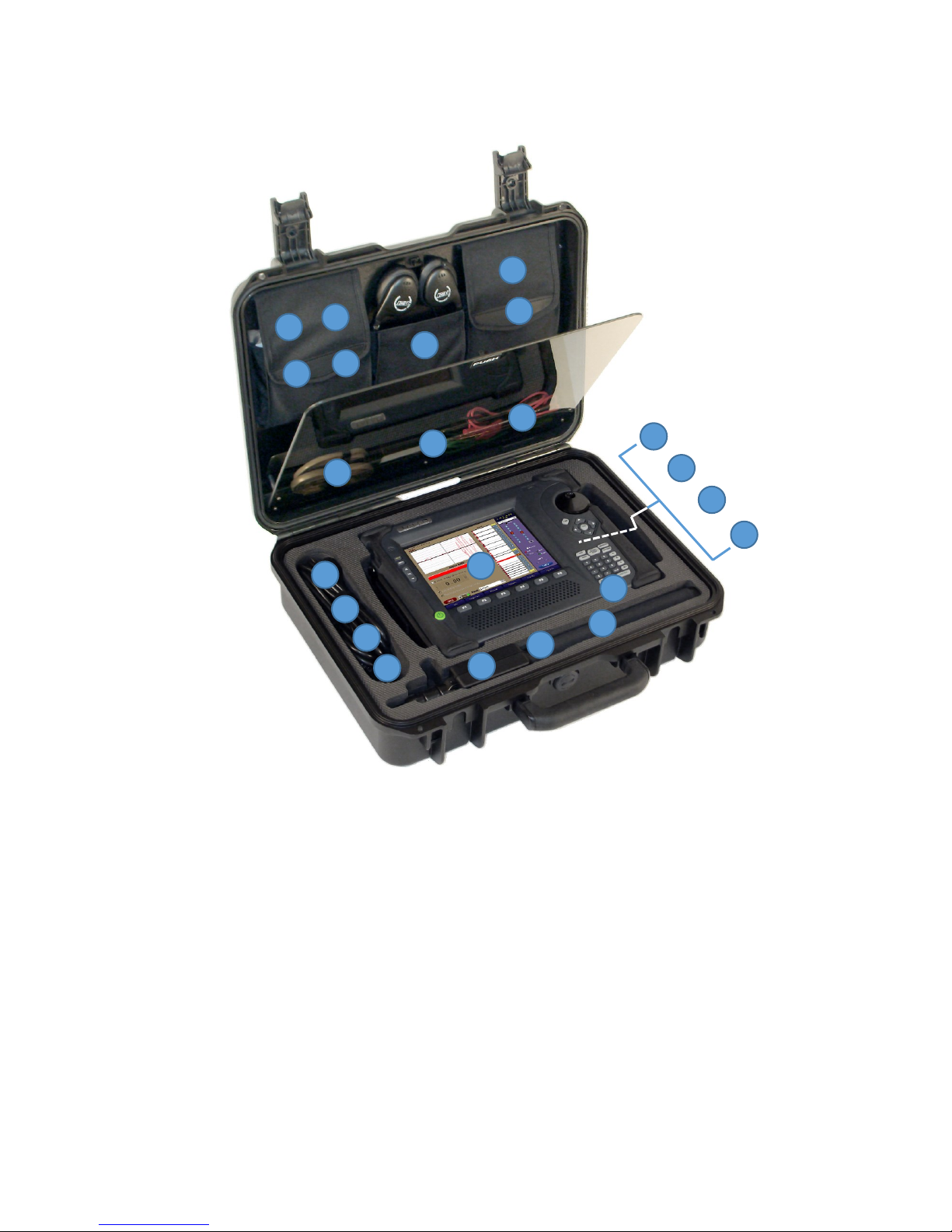
CASE CONTENTS
1 2 3
4 5 6
7
8
9
10
11
12
13
14
15
16
17
18
19
20
21
22
23
1. TALAN 3.0
2. US & Euro power cords
3. 15V adapter - for connecting power supply
4. VoIP adapter
5. Short network cable
6. HLP - Harmonic Locator Probe
7. Locator Probe Antenna
8. Compact Flash Memory Card - installed
9. RF Probe - 10 MHz - 2 GHz
10. DA-8000 Directional Antenna - 1.5 - 8 GHz
11. SMA-SMB - DA-8000 Connector Cable
12. SMB-SMB - DA-8000 Connector Cable
13. Lithium Ion rechargeable battery
14. 8 and 6 conductor phone cables
15. End of Line Box
16. Test Leads - red and green (earth ground)
17. Stylus - for use with the TALAN touchscreen
18. 66 Block Adapter
19. Red and black test probes
20. 8 Clip Breakout Cable
21. Headphones
22. CAT5 Patch Cable
23. 9V Battery
3
Page 4
Telephone & Line Analyzer
User Manual
This document is intended to provide guidance and instruction on using the TALAN 3.0
Telephone and Line Analyzer for telephone testing.
The overall effectiveness of this product, and of any surveillance countermeasure, is dependent
on the threat level and the user’s ability to properly utilize the appropriate equipment.
REI offers the world’s largest commercially available Technical Security training facility. Training
courses include classroom instruction and hands-on exercises where students perform sweep
exercises in “live” environments utilizing “target rich” project rooms. The progressive course
curriculum is designed for the beginner or the seasoned Technical Security Technician.
Regularly scheduled courses are taught monthly; visit REI’s website (www.reiusa.net) or contact
REI (sales@reiusa.net) for training dates.
4
Page 5

Research Electronics International, LLC
455 Security Drive, Cookeville, TN 38506 U.S.A.
(800) 824-3190 (US Only) • +1 931-537-6032
www.reiusa.net
Revision 3.01
© COPYRIGHT RESEARCH ELECTRONICS INTERNATIONAL
REI products are designed and intended for legal commercial applications, however because
laws and regulations vary from state to state and country to country, it is the sole responsibility
of the purchaser and user/operator to check and comply with all applicable laws and
regulations for the possession and operation of this equipment before and after making a
purchase.
This manual contains proprietary information intended solely for use with the TALAN
Telephone and Line Analyzer.
Information contained in this manual including product operation and specifications is subject
to change without notice.
Any product or brand names contained in this manual are used only for identification purposes
and are trademarks or registered trademarks of their respective holders.
NOTE: The overall effectiveness of any technical surveillance countermeasure is directly
dependent on the level of threat and the user’s ability to properly deploy the appropriate
countermeasure. REI’s Center for Technical Security offers training on technical surveillance
countermeasure equipment.
OWNER’S RECORD
The Serial Number of each TALAN is located on the underside of the unit. Please record this
number and refer to it whenever you contact your dealer or Research Electronics International
concerning this product. Note: Removal or alteration of the serial number automatically voids
all warranties of this product.
MODEL: TALAN
SERIAL NUMBER: __________________
© Copyright Research Electronics International LLC
5
Page 6

BASIC TALAN OPERATIONS
BASIC TALAN OPERATIONS .................................................................................................... 7
Battery Charging and Power Control ....................................................................... 7
Updating the Software and Firmware ..................................................................... 7
Saving Screen Shots to Thumb Drive ....................................................................... 7
Touch Screen and Keypad ....................................................................................... 8
Common Functions ................................................................................................. 8
Information Display ................................................................................................ 9
INPUTS AND AUTOMATIC SWITCHING ................................................................................. 11
TEST DATABASE MANAGEMENT .......................................................................................... 13
TESTING CONCEPTS AND RECOMMENDED TEST SEQUENCE .................................................. 17
Testing Locations .................................................................................................. 17
VoIP Wiring and Using the TALAN VoIP Adapter .................................................... 18
Testing Stages ....................................................................................................... 19
Summary of Recommended Tests ......................................................................... 20
Automated Sequencing and Manual Operation ..................................................... 22
Test Types ............................................................................................................ 24
Test Type Configuration Tips ................................................................................. 26
Save Sequence Data Functions .............................................................................. 27
MANUAL TEST FUNCTIONS .................................................................................................. 29
Save/Recall for Manual Test Functions .................................................................. 30
Save/Recall Data Example ..................................................................................... 31
Save Data to a Target Example .............................................................................. 34
DMM – Digital Multimeter .................................................................................... 36
DMM (Advanced Shield and EarthGround Testing) ................................................ 38
Audio ................................................................................................................... 40
Audio (Advanced Shield and EarthGround Testing) ................................................ 45
Classify Pairs ......................................................................................................... 47
FDR Frequency Domain Reflectometer .................................................................. 49
RF Analysis ........................................................................................................... 50
NLJD Line Non-Linear Junction Detection .............................................................. 54
VoIP (Overview, Connections, Mirroring…) ............................................................ 58
VoIP Plus+ (Advanced Detection and Analysis) ...................................................... 62
VoIP Analysis ........................................................................................................ 69
Line Bias ............................................................................................................... 71
A/B Comparison ................................................................................................... 72
HARMONIC LOCATOR PROBE: LINE TRACING AND TAP DETECTION ...................................... 74
HLP Locator Probe Display .................................................................................... 76
HLP Controls ......................................................................................................... 77
HLP Modes of Operation ....................................................................................... 77
Service Routines ................................................................................................... 79
Misc. Displays ....................................................................................................... 80
HLP Battery Compartment .................................................................................... 80
HLP Headphone Jack ............................................................................................. 81
TALAN SPECIFICATIONS ....................................................................................................... 82
6
Page 7

BASIC TALAN OPERATIONS
BASIC TALAN OPERATIONS
Battery Charging and Power Control
The TALAN has a built-in battery charger. To charge the battery, simply plug the power adapter
into the AC adapter port while the battery is in the TALAN.
Expected charge time: 1.5 hours with the TALAN off (3+ hours with TALAN operational).
Expected run time (on battery): 4 hours.
Note: It is recommended that the TALAN battery be recharged on a regular basis during
extended periods of storage (3 months or more) to prevent damage to the battery.
Additionally, when storing TALAN for long periods (1 month or more), it is recommended that
the battery be removed from the unit and placed in the storage compartment in the case.
Storing the TALAN with the battery in the unit can deplete it more rapidly, potentially
shortening the life of the battery.
Updating the Software and Firmware
Software updates (in the form of a .FIX file) will be available on-line or by contacting REI at
sales@reiusa.net.
Place the downloaded .FIX file on a USB thumb drive.
Plug the thumb drive (with .FIX update file) into the TALAN.
Press the F6 (System) button and choose Update from the pop-up menu.
Highlight the .FIX file and press the OK button.
The TALAN will now update the software/firmware. Follow any on-screen directions as the
TALAN may need to be restarted for the update to take effect.
Remove the thumb drive and save the .FIX file as a back-up.
Note: Check REI’s website or the REI TSCM Newsletter for software update notification.
If you have any questions, contact REI at sales@reiusa.net.
Saving Screen Shots to Thumb Drive
To assist in report writing, the TALAN provides the ability to capture screen shots from the
TALAN display. These images are created as BMP (bitmap) images and stored to a thumb drive.
To use this function, the thumb drive must be inserted in the USB port on the front of the
TALAN. Press the following key sequence to store the current screen image:
SHIFT
HELP
If the screen shot is successful, the TALAN logo in the upper right corner will cycle through
background colors of green and yellow before returning to black. If the screen shot is not
successful (e.g., no USB drive), the TALAN logo will cycle through background colors of blue and
7
Page 8

BASIC TALAN OPERATIONS
Hard Button
Function
A
Audio Dashboard
B
Line Bias Dashboard
C
Connection Dashboard
MANUAL
Manual Test Menu
F4
Test Options and Summary Dashboards
OPTIONS
Test Options and Summary Dashboards
START/STOP
Start/Stop a test
red before returning to black. If the volume is turned up, there will be an audible sound that
indicates the image is being saved.
Touch Screen and Keypad
The easiest method to access and control TALAN functions is to use the built-in touch screen.
There is a stylus located in the left grip which will give the most precise control of the touch
screen.
To calibrate the touch screen, press the F6 (System) button and select Touch Screen from the
menu. Follow the on-screen instructions. Calibration should only be required after a complete
software update is performed.
Common Functions
In using the TALAN, you will discover that there are several functions that are accessed very
often. The user interface was designed to quickly access these functions using hard buttons.
Some of the most common functions or button/display pairs are:
8
Page 9
BASIC TALAN OPERATIONS
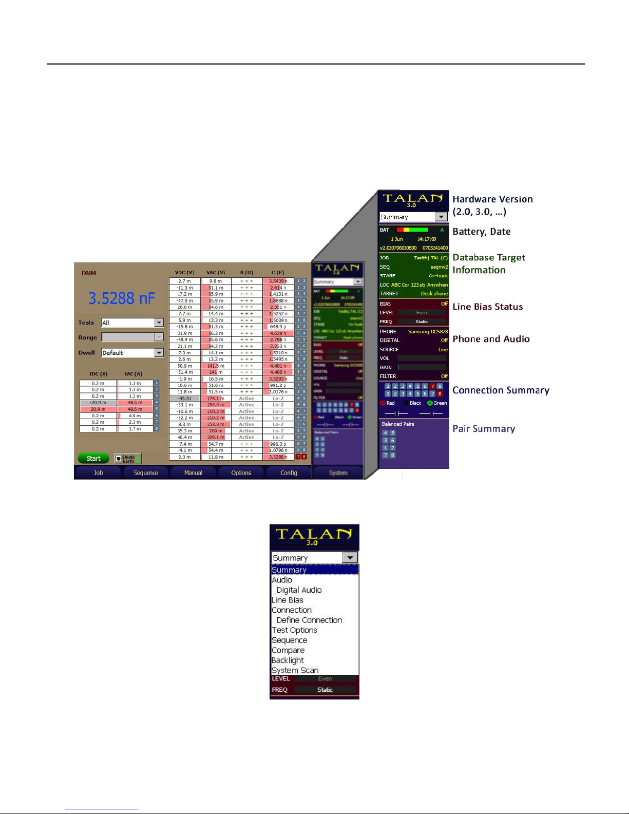
Information Display
While using the TALAN, the right hand side of the display is used for the dashboard functions
and to provide overall information about the testing process. You can always return to this
high-level summary dashboard by pressing the F4 (Summary) button. It may be necessary to
press F4 multiple times depending on the currently displayed dashboard. You can access
various dashboards by using the pull-down menu at the top of the display.
All dashboards can be accessed using the pull-down menu at the top each dashboard.
9
Page 10
BASIC TALAN OPERATIONS
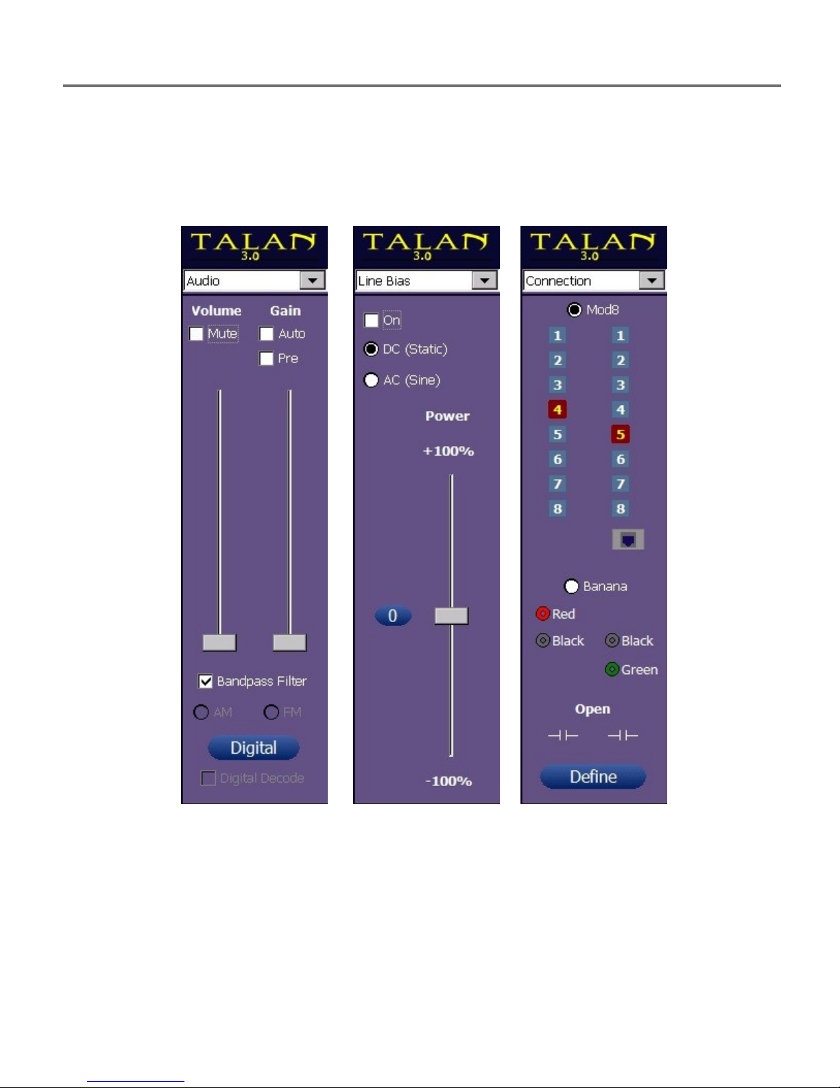
Images of dashboard screens are below: Audio, Line Bias, and Connection. These are accessed
by pressing A (Audio), B (Bias), or C (Connection) buttons. Since these dashboards are accessed
often, they were assigned special hard buttons for quick access.
A B C
10
Page 11

1 2 3 4 5 6 7 81 2 3 4 5 6 7 8
The TALAN provides modular 8 type connectors (Line, Phone), banana plug connectors
(Black/Ring, Red/Tip, Green/Earth), an expansion port (for future applications), and an RF
antenna input.
The Expansion port will be used for future upgrades as developed, but currently has NO
The RF Antenna port is used for RF broadband analysis using the 2 provided antennas.
The banana plugs can be used for any type of miscellaneous testing.
The modular 8 connectors provide for switching between selected pairs for most types
With TALAN 3.0, conductors 1:8 can also be tested against the Shield on the MOD8 connector,
and also against the EarthGround Banana Jack Connector.
INPUTS AND AUTOMATIC SWITCHING
INPUTS AND AUTOMATIC SWITCHING
function.
Warning: Even though the Expansion port is currently unused, it is still connected to the
test input circuitry. Devices other than those provided by REI should NEVER be attached
to this connector.
Warning: The TALAN circuitry is designed for testing sensitive phone networks and
equipment. The banana plugs should NOT be connected to high current or high voltage
test points such as power outlets.
of wiring. For example, if a cable has 8 conductors, the typical wiring pairs are as follow:
4:5 is typically the primary pair.
3:6 is the secondary pair
1:2 is an auxiliary pair
7:8 is an auxiliary pair
Using these 8 conductors, it is important to note
there are 28 possible combinations to consider.
For example:
1:2, 1:3, 1:4, 1:5, 1:6, 1:7, 1:8
2:3, 2:4, 2:5, 2:6, 2:7, 2:8
3:4, 3:5, 3:6, 3:7, 3:8
4:5, 4:6, 4:7, 4:8
5:6, 5:7, 5:8
6:7, 6:8
7:8
11
Page 12
INPUTS AND AUTOMATIC SWITCHING
The switching matrix in the TALAN provides for automatic switching and test measurement for
all of these possible combinations. Users can also specify only testing a single wire pair or the
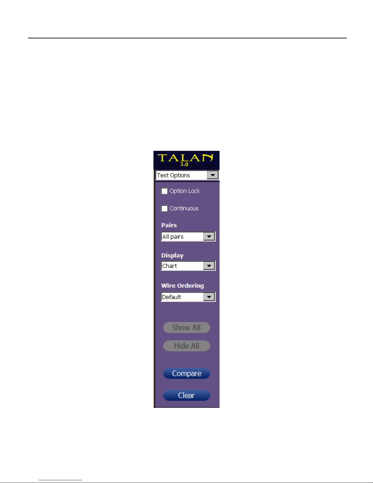
balanced pair combinations as described later in this manual. For most test functions press the
F4 (Options) button and select All Pairs, Balanced Pairs, or Single Pair.
Note: the Continuous function allows for repeated sequential testing of the selected
function and wire pair(s).
Note: the Option Lock function provides a way to maintain or ‘lock’ the current test
option settings while navigating between multiple manual tests and touch screen taps.
12
Page 13
TEST DATABASE MANAGEMENT
TEST DATABASE MANAGEMENT
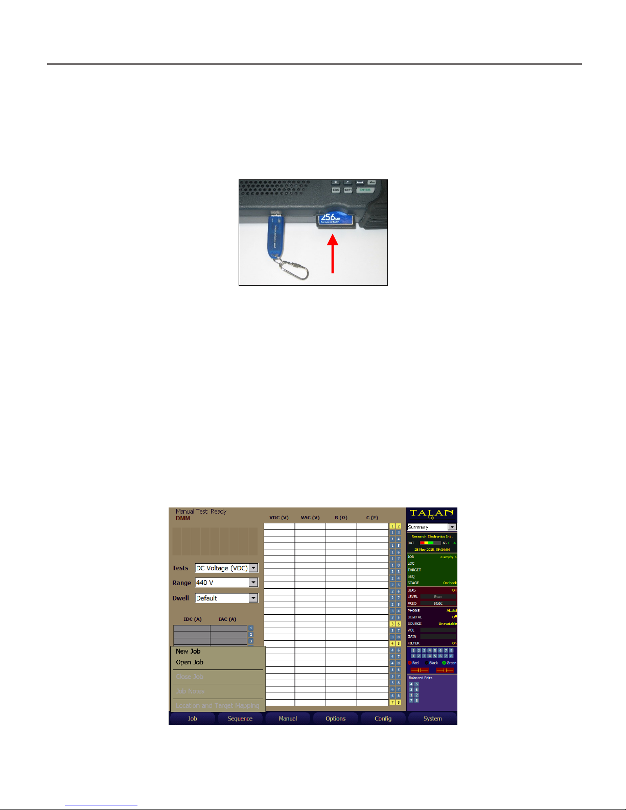
All TALAN test data can be saved to an external memory system. This memory system can be either a
USB thumb drive or a Compact Flash card. Ports for both of these memory media are located at the base
of the unit. Once test data has been saved, it can be further analyzed using the TALAN’s A/B
Comparison function detailed later in this manual.
The USB thumb drives may be installed or removed at any time while the product is in use. However, the
Compact Flash memory must be installed in the TALAN on startup to be properly recognized and
accessed.
A USB keyboard may be connected to the TALAN to facilitate alphanumeric entry for various input fields.
USB storage devices must be formatted with a FAT file system, such as FAT32, for use with the TALAN
unit. Devices that are formatted with the NTFS file system will not be recognized by the TALAN.
Windows operating systems limit the storage capacity of a FAT32 partition to less than 32 GB when
formatting. Third party software does exist which will allow you to format a larger partition using FAT32.
Prior to saving data, it is necessary to define a Job Name. This creates a unique database under the Job
Name so that all test data associated with this Job can be saved in the same database structure. Press
the F1 (Job) button and select New Job (see below).
13
Page 14
TEST DATABASE MANAGEMENT
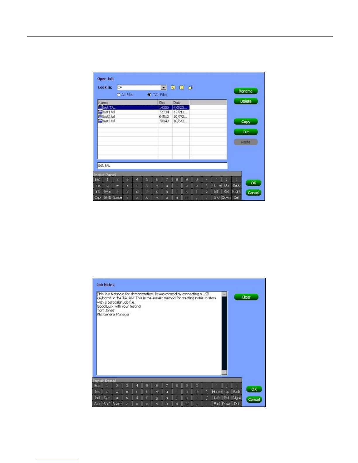
You can define the Job name using the stylus and the provided keypad. Press the OK button to
accept the Job name. You can also select the storage medium, either USB for the thumb drive
or CF for the Compact Flash card.
You can also use this screen to cut and paste a complete Job Database from one storage
medium to another.
To enter specific notes about a Job, select the Job Notes from the F1 (Job) menu.
A USB keyboard is recommended for entering text quickly.
14
Page 15
TEST DATABASE MANAGEMENT
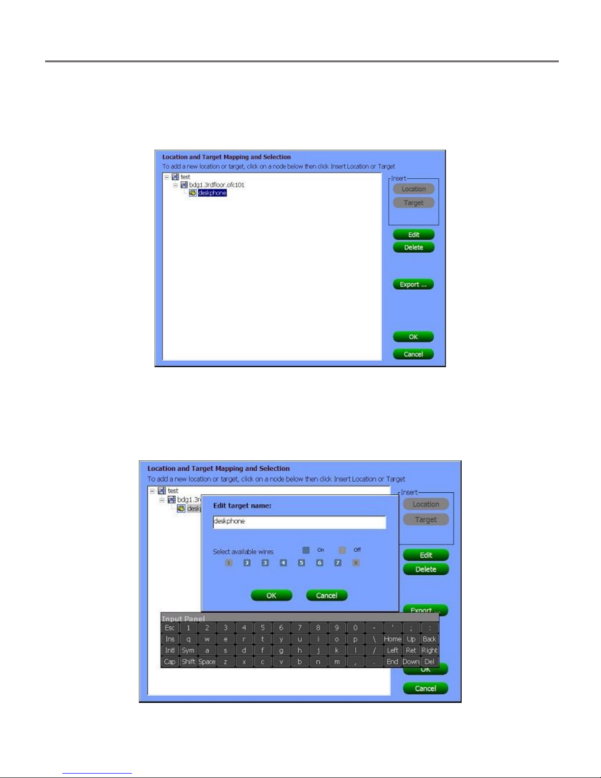
You will also notice Targets and Locations under the Job menu. This selection is used to define
additional information about the particular target being tested. Locations will be used to
identify specific locations (address, building number, building floor, office number etc.) within a
Job. Target will be used to identify a specific target (phone set, network access point, etc.) to
analyze within a location.
Available Wires define how many wires are used in the phone cord. A maximum of 8
conductors may be in a phone cord and the conducting pairs should always be defined from the
center outward. For example, a 2-wire system should be defined with 4 and 5 selected and all
unused pairs de-selected. If a 4-conductor phone cord is used, then the 1, 2, 7, and 8 should be
de-selected. The example below shows a typical 6 wire system setup.
15
Page 16
TEST DATABASE MANAGEMENT
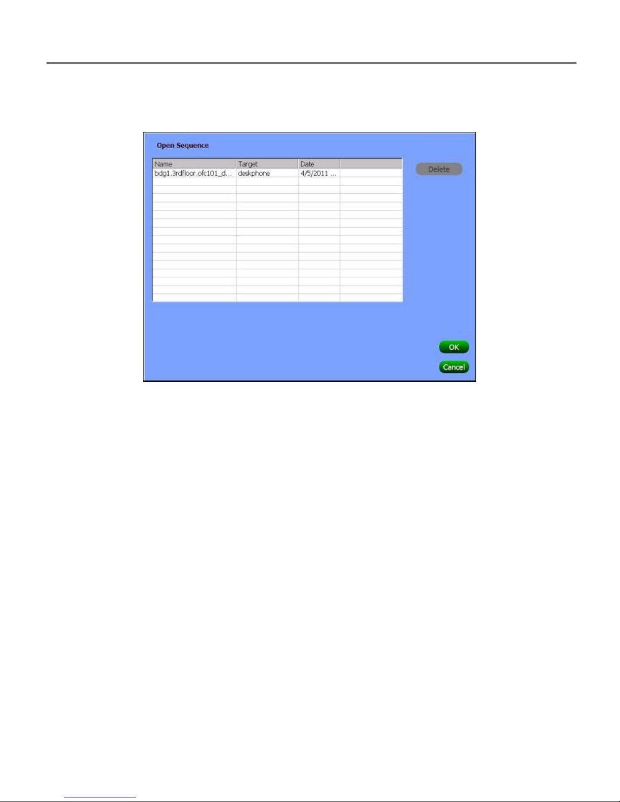
Prior to beginning testing, it is important to define the test sequence. The test sequence name
is used by the database to identify the series of tests that are performed on a target. For a
single target on a job, you may perform multiple test sequences.
16
Page 17
TESTING CONCEPTS AND RECOMMENDED TEST SEQUENCE
Testing at Phone Set
Block Testing
TESTING CONCEPTS AND RECOMMENDED TEST SEQUENCE
Testing Locations
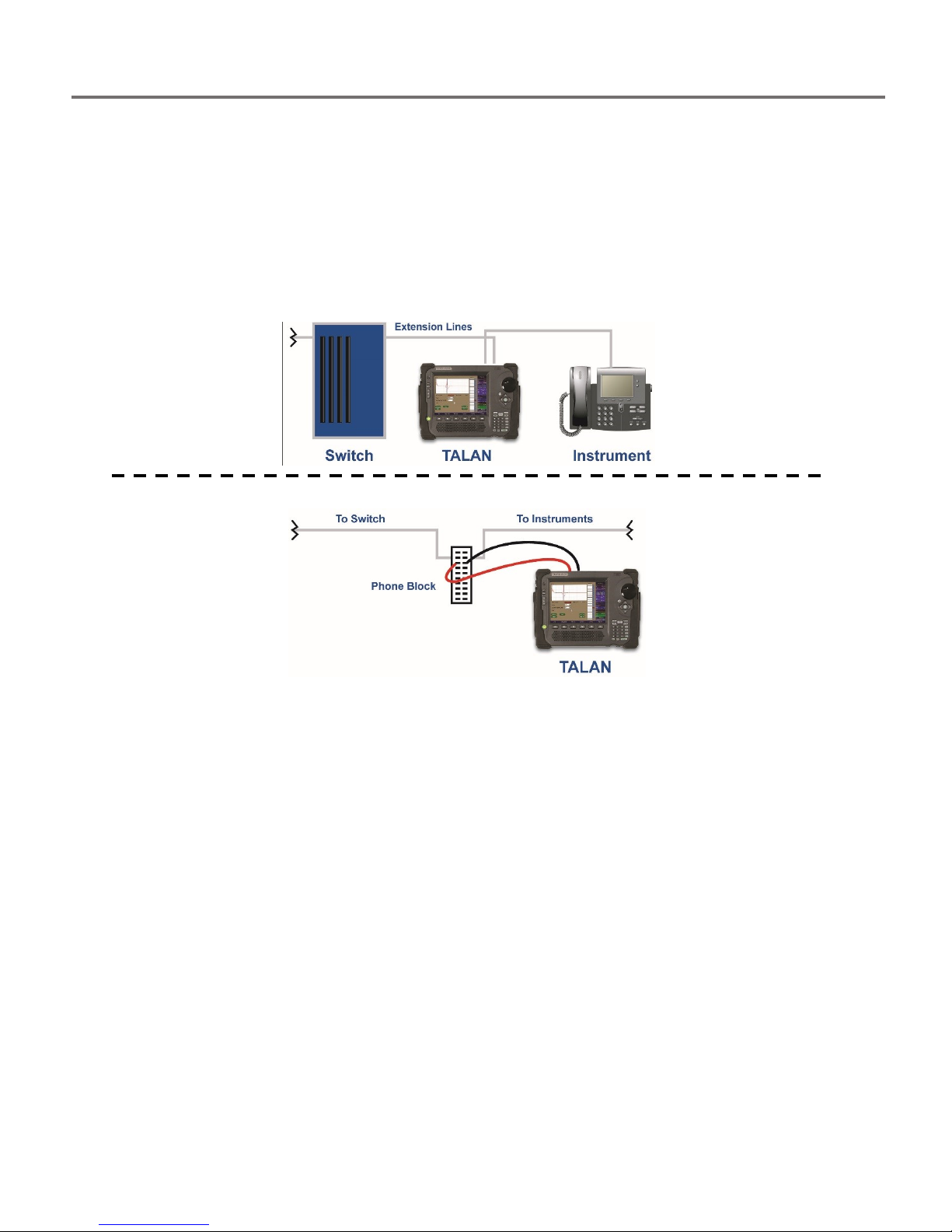
The TALAN can be used to test a phone line from several different testing points.
It is important to understand that prior to interrupting the phone line you should first verify
that there is no audio passing down the line. Therefore, regardless of where you test the line,
you should first use the banana plugs, connect to the main audio pair and test for audio. This is
often easier at an intermediate block. Then, it is recommended that the user start testing at the
phone set. For the remainder of this document, it is assumed that the testing is performed at
the phone set.
17
Page 18
TESTING CONCEPTS AND RECOMMENDED TEST SEQUENCE
VoIP Wiring and Using the TALAN VoIP Adapter
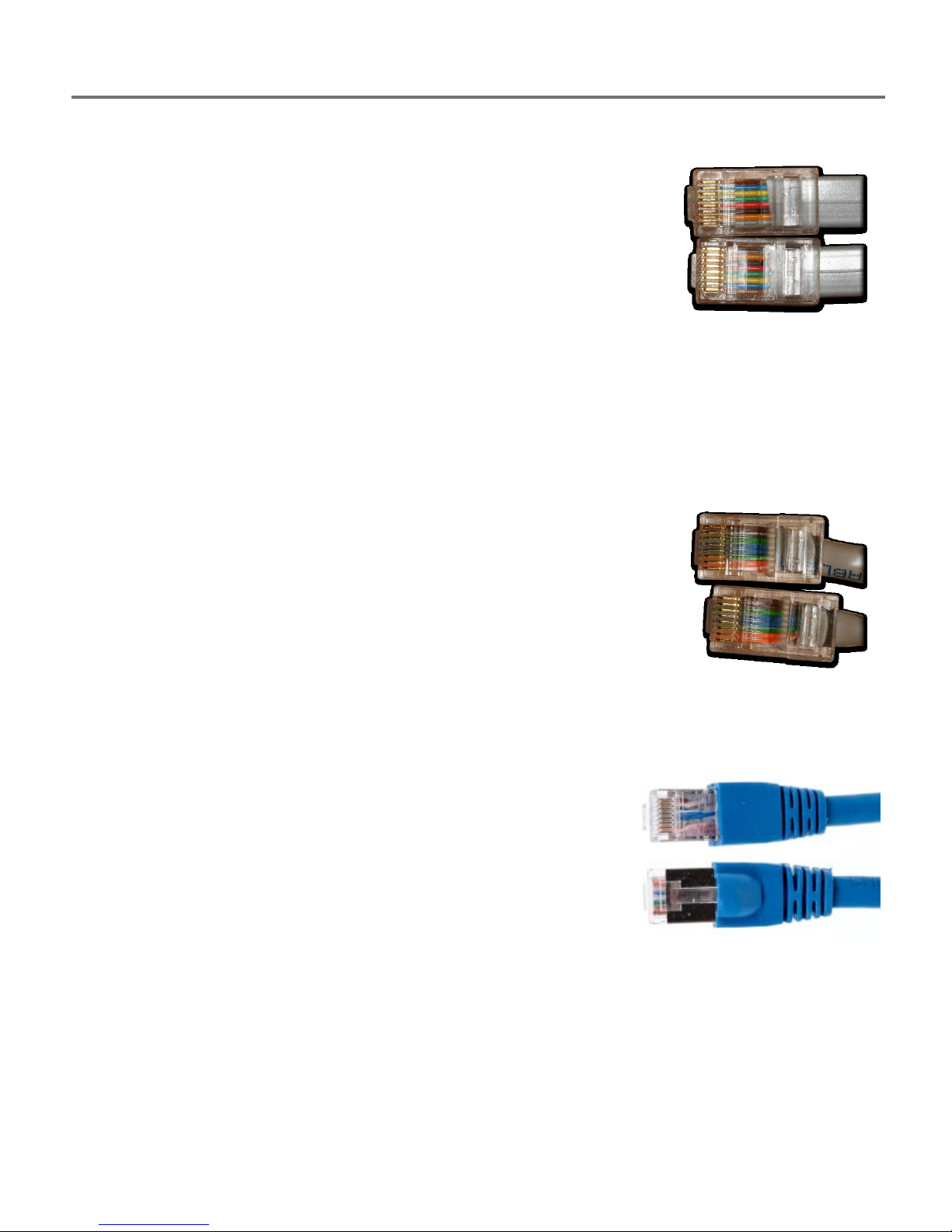
Traditional Telecom Cables
Typical analog and digital phone systems use a “reversed” modular 8conductor cable (where Pin 1 on one end of the cable corresponds to Pin
8 on the other end of the cable, Pin 2 to Pin 7, and so on). Flat modular
cords are most often in this reversed format. This reversed wiring can be
seen in the image at the right (note the reversed colored conductors on
each connector).
The TALAN can be used “in-line” with a phone system using the TALAN’s two modular jacks
which are identified as LINE and PHONE. The modular jacks on the TALAN are wired straight
through to allow for most common telephone systems without the use of a special crossover or
special test adapter cable. Pin 1 on the LINE jack corresponds to Pin 1 on the PHONE jack and so
on.
Cat5 Cables
Unlike the reversed modular flat cables found in most voice systems, Cat5
twisted pair cables, which are used in VoIP phone systems and some
digital phone systems, are wired in a “straight though” manner (Pin 1 to
Pin 1, Pin 2 to Pin 2, etc.). Typically, VoIP systems use Pins 1, 2, 3 and 6 of
an eight wire twisted pair cable. This straight through wiring is shown in
the image to the right (note the colored conductors are in the same order
in both connectors).
Cat6 Shielded Cables
CAT6 cables are based on the CAT5 design, however, CAT6
cables utilize shielding and potentially a drain wire and/or braid
to help reduce interference between conductors and also help
reduce interference between the CAT6 cable and other cables.
However, this additional shielding could be used as a carrier for
electronic information. For example: placing one lead of a
microphone on the shield and placing the other lead of the
microphone to one of the 8 CAT6 conductors.
TALAN 3.0 provides methods to test MOD8 conductors against
shields in CAT6 shielded cables.
18
Page 19

TESTING CONCEPTS AND RECOMMENDED TEST SEQUENCE
Testing Stages
When testing with the TALAN, there are different testing conditions that must be considered. We
have defined these conditions as test stages and they are:
1. On-Hook Test Stage
2. Off-Hook Test Stage
3. Phone Disconnected Stage
4. Open Circuit Stage
5. End-of-Line Stage
It is not necessary to conduct all possible tests in each of these test stages; therefore we have
provided a description and benefit for each of these stages.
1. On-Hook Test Stage
Handset on hook, TALAN in line with phone set.
No audio should exist on any pair.
Characterize system parameters such as voltage.
Test for RF Carrier Current signals
Tests: DMM, Audio analysis, Broadband RF and Activity level
2. Off-Hook Test Stage
Handset off hook, a call is in progress, audio should be passing through the line only on
the main pair.
To validate Audio Testing. Test for audio on odd pairs.
Characterize system parameters such as voltage and compare with On-Hook Case.
Test for RF Carrier Current signals
Tests: DMM, Audio analysis, Broadband RF and Activity level
3. Phone Disconnected Stage
Phone disconnected from line, but line is connected to digital switch.
Characterize system parameters such as voltage.
Analyze Line with FDR, and compare FDR results between pairs to look for taps
Tests: DMM, FDR
4. Open Circuit Stage
Line is not connected to switch or phone set. No electronic connections should exist
anywhere on the line. Line is completely isolated from everything except the TALAN.
Test Line with bias voltage for attached microphones
Analyze Line with FDR, and compare FDR results between pairs
Test Line for taps and microphones
Tests: NLJD, FDR, Capacitance
5. End-of-Line Stage
The line is isolated as in the above stage however, there is a passive load (no electronics,
only a resistive network) attached to the end of the line to improve FDR sensitivity and
provide loop resistance test.
Analyze Line with FDR, and compare FDR results between pairs and with Open
Circuit stage
Test Line for serial taps using loop resistance
Tests: FDR, Loop resistance
19
Page 20

TESTING CONCEPTS AND RECOMMENDED TEST SEQUENCE
Summary of Recommended Tests
The testing stages listed above result in large amounts of test data. However, it is important to consider
which tests provide the most benefit in the shortest amount of time. For this situation we recommend
the following simplified and reduced test outline:
Set-Up
1. Set-up the TALAN prior to making test measurements. Methods for performing these steps
are provided later in the manual.
a. Enter a Job Name prior to testing.
b. Enter the Location and Target information.
c. Define the number of conductors that exist on the line.
d. Define a Sequence Name.
e. Install digital phone type (i.e., Avaya, Nortel, Samsung…).
Non-Alerting
2. Without disconnecting the line or altering the handset, test the line for audio using the
banana plugs.
a. Find a place somewhere on the line to gain access to the pairs.
b. Test each pair for voltage to verify the main active pair.
c. Test each pair for both analog and digital Audio.
d. Test each pair for carrier current signals with the RF Level & Spectrum tests.
3. Using the RF Antennas, test for RF energy coming from the telephone.
Single Ended Testing
4. At the phone set, connect the TALAN in line.
a. If the Telephone cable is a FLAT cable, then a FLAT patch cable should be used between
the TALAN and the wall jack.
b. If the Telephone cable is a Twisted Pair cable, a Twisted Pair patch cable (typically CAT5)
should be used between the TALAN and the wall jack.
5. With the Phone ON HOOK (Stage 1)
a. Test all pairs for DC voltage to get a basis for operating voltage & DC current.
b. Test all pair combinations for audio. There should be NO audio.
6. With the Phone OFF HOOK and a call in progress (Stage 2)
a. Test all pairs for audio (Note: you may also hear audio on any pair combination that has
either conductor from the main pair because the TALAN audio system can pull audio
from one wire in a balanced pair).
b. Test all pairs for DC voltage. This gives a basis for the operating voltage.
7. With the Phone Disconnected (Stage 3)
a. Classify the Pairs (define balanced pairs).
b. Test the main pairs with the FDR. Put all FDR traces on the screen and visually compare.
They should be very similar. It is recommended to concentrate only on the balanced
pairs.
Double Ended Testing
8. With the Phone Set Disconnected and the Switch Disconnected (Stage 4)
a. Test all pair combinations with the NLJD. There should be NO response on any pair
combinations. THIS IS THE MOST RELIABLE TEST.
9. With the Phone Set Disconnected, the Switch Disconnected, and the End-Of-Line terminator
placed on the line (Stage 5)
a. Test main pairs with the FDR to indicate locations of electronic connections.
10. Use the Locator Probe as needed to find the tap.
20
Page 21
TESTING CONCEPTS AND RECOMMENDED TEST SEQUENCE
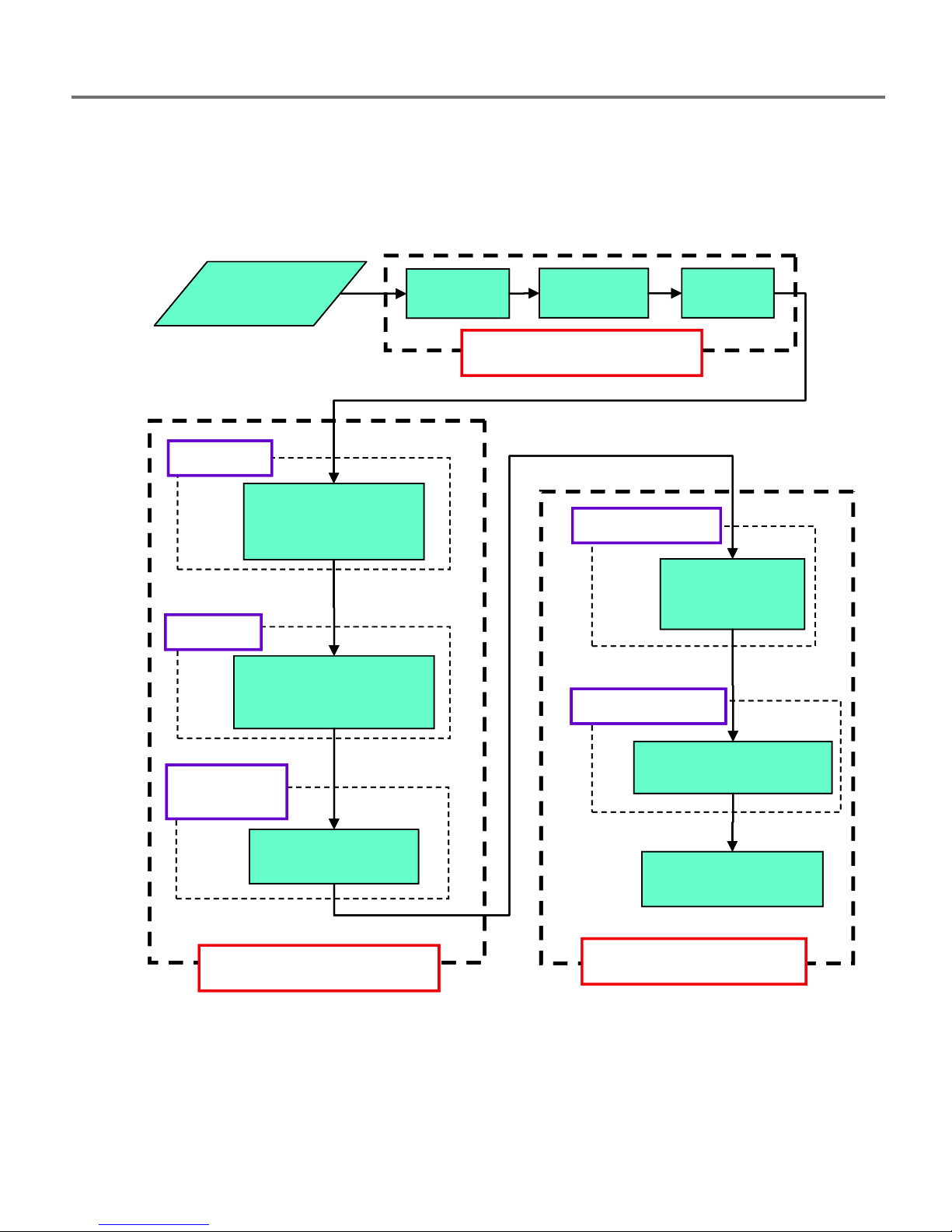
Recommended Test Sequence
Recommended Test Sequence
Job
Definition
VDC, VAC
Spectrum Test
Audio Listen
Pair Classification
FDR
Measure VDC, VAC
Spectrum Test
Audio Listen
Off Hook
DC Volts
NLJD
Capacitance??
Bias Tests??
FDR
(only if NLJD is Pos)
Locator Probe
(Only if requird)
On Hook
Disconnect
Phone
Open End Test
Terminated End
Single End Test
Double End Test
Audio Test RF Test
Non-Alert Test
Recommended Test Sequence
Recommended Test Sequence
Job
Definition
VDC, VAC
Spectrum Test
Audio Listen
Pair Classification
FDR
Measure VDC, VAC
Spectrum Test
Audio Listen
Off Hook
DC Volts
NLJD
Capacitance??
Bias Tests??
FDR
(only if NLJD is Pos)
Locator Probe
(Only if requird)
On Hook
Disconnect
Phone
Open End Test
Terminated End
Single End Test
Double End Test
Audio Test RF Test
Non-Alert Test
21
Page 22
TESTING CONCEPTS AND RECOMMENDED TEST SEQUENCE
Automated Sequencing and Manual Operation
The TALAN has many test functions that can be performed in either an Automated Sequence
Mode or Manual Mode. The main difference is that the Automated Sequence Mode is designed
to walk the user through the previously recommended test sequence while the Manual Mode is
designed to allow the user to go to any specific tests and completely control the parameters
and conditions of the tests. Manual Mode is most useful for testing for specific items of interest
while the Automated Sequencing is recommended for a complete evaluation of the line. In both
modes, the testing screens are very similar; however, the Automated Sequencing Mode test
screens have a green background while the Manual Mode test screens have a brown
background.
This section will describe how to utilize the Sequence mode. However, the details of the actual
tests being performed will be described later as Manual Tests functions.
22
Page 23
TESTING CONCEPTS AND RECOMMENDED TEST SEQUENCE
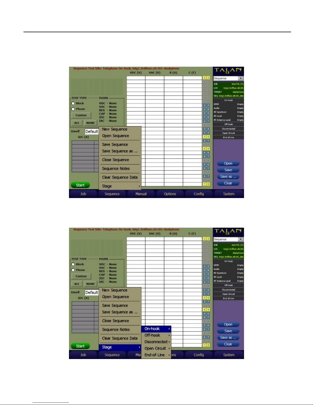
To access the Sequence testing, press the F2 (Sequence) button and simply begin selecting the
desired tests under the Stage submenu. It is highly recommended that the test stages and test
functions be performed in the order that they are presented.
Within the test Sequence, different stages will be defined as previously described and specific
tests will be available under these test stages as indicated by the example menu structure
below.
23
Page 24
TESTING CONCEPTS AND RECOMMENDED TEST SEQUENCE
TEST TYPE
Block
Phone
VDC (Voltage DC)
Balanced Pairs
Balanced Pairs
VAC (Voltage AC)
None
None
RES (Resistance)
Balanced Pairs
Balanced Pairs
CAP (Capacitance)
None
None
IDC (DC Current)
All Wires
None
IAC (AC Current)
None
None
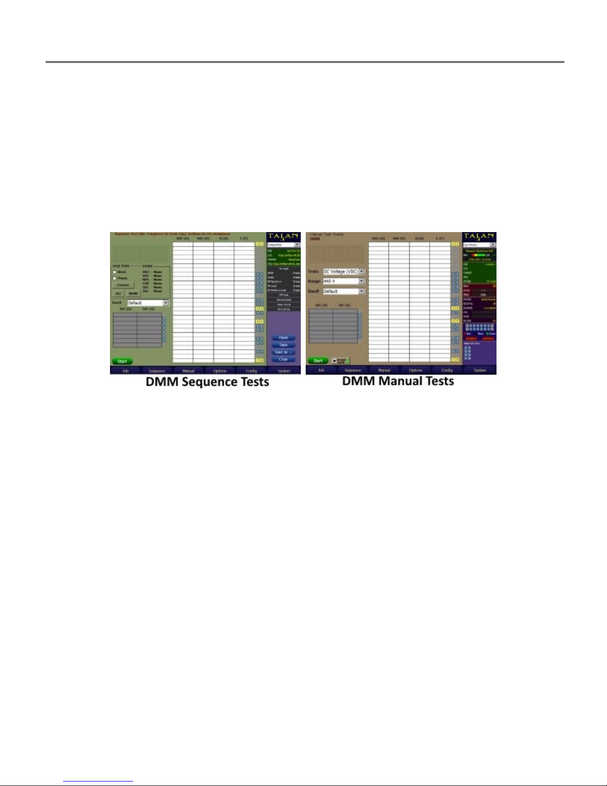
Test Types
When executing the tests under the Sequencing Mode, the tests that the TALAN will perform
includes those selected using the TEST TYPE selection. The TALAN will automatically utilize
default settings for the various test functions.
The TEST TYPE can be configured by the user as necessary. There are “quick set” buttons for
Block, Phone, ALL, and NONE. These buttons will set the appropriate set of tests for VDC (Volts
DC), VAC (Volts AC), RES (Resistance), CAP (Capacitance), IDC (current DC), and IAC (current
AC). Below is an example of the Stage 1 (On-Hook) DMM tests where the TEST TYPE was set to
All Pairs and All Wires for all test types.
Subsequently, when START is pressed, the TALAN will test all pairs and wires for all tests.
The default factory settings for BLOCK and PHONE are as follows:
24
Page 25
TESTING CONCEPTS AND RECOMMENDED TEST SEQUENCE
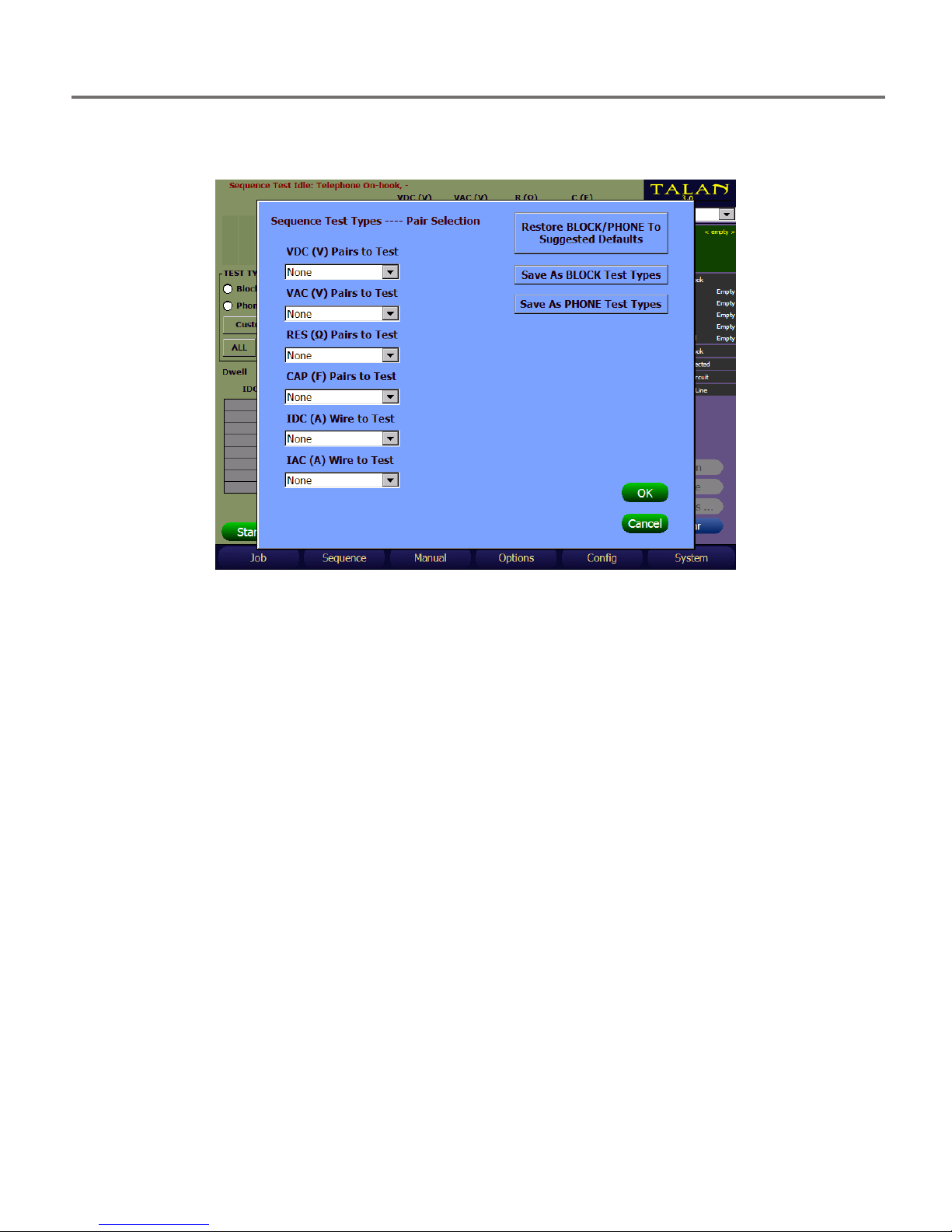
If a test combination other than BLOCK, PHONE, or ALL is desired, then the TEST TYPE pair /
wire selections can be set using the CUSTOM button.
Using the above shown display, each individual TEST TYPE can be modified to the desired
setting.
VDC, VAC, RES and CAP TEST TYPEs options are:
None This test type will not be performed on any pairs
Balanced For all balanced pairs where each wire in the pair is available, this test
will be performed.
All Pairs For all pairs available for this location, if each wire is available, then this
test will be performed.
IDC and IAC TEST TYPEs options are:
None This test type will not be performed on any wires
All Wires For all wires identified as available for this location, this test will be
performed.
When you have made the changes to the set of tests you want to run, select OK to exit the TEST
TYPE selection screen, which will save your changes for this test run, then select START to run
the test type configuration you have just defined. The TALAN will automatically progress
through the different TEST TYPEs using the settings you defined.
While on the TEST TYPE pair / wire selection screen, pressing Cancel will exit the TEST TYPE pair
/ wire selection screen and cancel type selections you have made in this session of the Test
Type selection screen.
25
Page 26

TESTING CONCEPTS AND RECOMMENDED TEST SEQUENCE
The TEST TYPEs selected when pressing BLOCK and PHONE can be changed for this TALAN. The
TEST TYPEs for this TALAN are remembered through power cycles.
To change the TEST TYPEs selected when pressing PHONE on the Sequence Mode DMM screen,
do the following:
Access the Test Type pair/wire selection menu by pressing the CUSTOM button
Setup the TEST TYPE configuration you want for PHONE for each TEST TYPE
Press Save As PHONE Test Types.
Likewise,
To change the TEST TYPEs selected when pressing BLOCK on the Sequence Mode DMM screen,
do the following:
Access the Test Type pair/wire selection menu by pressing the CUSTOM button
Setup the TEST TYPE configuration you want for BLOCK for each TEST TYPE
Press Save As BLOCK Test Types.
If at any time you want to go back to the factory settings as it was shipped from REI for PHONE
and BLOCK, then press the Restore BLOCK/PHONE to Suggested Defaults button.
The PHONE and BLOCK Test Type settings are retained during power cycles.
The Suggested Defaults cannot be changed.
Test Type Configuration Tips
It is not advisable to perform a Resistance test on pairs that have not been checked for VDC
because the TALAN applies DC Voltage to perform the Resistance test. Therefore, when you
select a Resistance test combination that has a pair that is not going to get tested due to the
current TEST TYPE selected for VDC TEST TYPE, the TALAN will automatically change the VDC
TEST TYPE to the same TEST TYPE as you selected for the Resistance TEST TYPE. A warning
message will be shown reminding you that this change automatically occurred to the VDC TEST
TYPE.
For example, assume you do the following:
Set VDC TEST TYPE to Balanced Pairs
Then set Resistance TEST TYPE to All Pairs
The TALAN will automatically change VDC TEST TYPE to All Pairs.
A Warning Message will appear.
However, the TALAN will allow you to select a lower set of pairs for VDC once the Resistance
TEST TYPE is set.
For example, assume you do the following:
Set Resistance TEST TYPE to All Pairs,
Then Set VDC TEST TYPE to Balanced or None.
The TALAN will permit this change, because it assumes that your selection is based on
knowledge of the state of the wires/pairs, however a Warning Message will appear.
26
Page 27

TESTING CONCEPTS AND RECOMMENDED TEST SEQUENCE
Red
background
indicates
data has
NOT been
saved.
Save Sequence Data Functions
As shown below, when data has been measured but not saved, the surrounding field will be
indicated in red on the summary dashboard to the right. To save this data, select Save as… to
store this data into the database structure. When data is saved, it will be indicated with a blue
field.
27
Page 28

TESTING CONCEPTS AND RECOMMENDED TEST SEQUENCE
Blue
background
indicates
data HAS
BEEN
SAVED.
All of the remaining sequencing can be completed by selecting the testing stages and suggested
tests in the order that they appear on the screen. For example, after the DMM test sequence is
completed, it is recommended to continue the sequence with other available tests within this
Stage. It is recommended that each Stage be tested in order. All test functions are described in
detail in the following section entitled Manual Test Functions.
28
Page 29

MANUAL TEST FUNCTIONS
MANUAL TEST FUNCTIONS
This section provides an overview of all TALAN testing functions. The figure below shows the
available manual testing options accessible via the F3 (Manual) or the MANUAL push button.
The manual test functions are CLASSIFY PAIRS, DMM, AUDIO, RF LEVEL, RF SPECTRUM, RF
ANTENNA LEVEL, NLJD, FDR, VOIP ANALYSIS, VOIP PLUS+, and LINE TRACER.
The manual test controls for each function are very similar. For each test, once the test pairs
have been defined (single, balanced or all) under the Test Options dashboard, and any other
test parameters have been specified, the test is started by pressing the START/STOP button or
tapping Start on the screen.
29
Page 30

MANUAL TEST FUNCTIONS
Save/Recall for Manual Test Functions
For all Manual Test functions, the user can save the current active measurement data for later
review and / or comparison with previous measurements.
There are two methods to save data that has been collected by the Manual Test functions.
The first method is to store the data to an open Job using the Save Data item under the F3
(Manual) button. This data can be recalled on the TALAN at a later date. It can also be
transferred to a PC via USB or a Compact Flash card and viewed in the Manual Data section of
TALAN Data Viewer. The data is organized by test method, e.g. DMM, FDR, etc. This method
requires careful naming of the data captured so that the user will understand where this data
actually came from when reviewing it on the PC with TALAN Data viewer.
The second method is to store the data to a target within an open Job using the Save Data to a
Target item under the F3 (Manual) button. This data can be transferred to a PC via USB or a
Compact Flash card and viewed in the Sequence Data section of TALAN Data Viewer. The data
is accessible in a logical tree structure that starts with the highest level location designation
(e.g. company name REIHQ). It can then be broken down into as many sub locations as
necessary, e.g. TrainingRoom, or PhoneCloset4 or PresidentsOffice, then finally to a given
Target, such as Deskphone or WallJackA231. This Save Data to a Target method places the
manually collected measurements into the same target that data is stored from the Sequence
DMM tests as outlined in the section titled Save Sequence Data Functions.
Using the Save Data method requires that the data name for the given measurements contain
sufficient information to identify all of the locations/sub-locations/targets. This makes the Save
Data to a Target method a more logical approach to organizing data for future retrieval /
comparison using the TALAN Data Viewer.
30
Page 31

MANUAL TEST FUNCTIONS
Save/Recall Data Example
To demonstrate the basic Save and Recall Data functionality, we have taken simple DC voltage
measurements of a full set of pairs (this test is explained later under Test Functions portion of
the manual). It is important to note that any measurements that are taken with the TALAN (i.e.
DMM, FDR, NLJD, Audio level, RF Spectrum trace, etc…) that are stored using the Store Data
method can be stored and associated with a Job in a Job Name Database. This data can later be
recalled for review or comparison on the TALAN or using the TALAN Data Viewer on a PC.
To save data so that it will be associated with a Job, that specific Job Database must be open.
To save the DC Voltage measurements taken in the Manual DMM test, select F3 (Manual) then
select Save Data.
31
Page 32

MANUAL TEST FUNCTIONS
Enter a name for this data, and press OK. You must be careful to document your filename and
data set name to keep track of the data that was stored.
To retrieve data from the manual database, select F3 (Manual) then select Recall Data. This is
beneficial when comparing current readings with previous readings looking for anomalies.
32
Page 33

MANUAL TEST FUNCTIONS
Select the name of the data set you want to recall, and select OK.
33
Page 34

MANUAL TEST FUNCTIONS
Save Data to a Target Example
Saving data so that it is associated with a target means that the data will get placed into the
Sequence Data for a target within a given Job database. This data can be accessed in the
Sequence Data section of TALAN Data Viewer.
The Sequence Data section presents the data in a tree representation starting with the main
top level location, through the various sub-locations, ending up at a given target.
To save data so that it will be associated with a Target, that specific target and its respective Job
Database must be open.
To save the DC Voltage measurements taken in the Manual DMM test, select F3 (Manual) then
select Save Data to a Target.
Select the stage for this test, e.g. On-Hook, Off-Hook, Disconnected, etc. for the appropriate
test type and physical setup. Note: This list of stages varies depending upon the test type
(DMM, Audio, etc.) and the stage selected.
34
Page 35

MANUAL TEST FUNCTIONS
Verify the name automatically created for this test, correct it if necessary, and select OK.
Verify the Data to save and Save Method (normally just use the defaults), and select OK.
The saved data can now be recalled on the PC using TALAN Data Viewer selecting the
appropriate TAL file for this job, in the Sequence Data section.
35
Page 36

MANUAL TEST FUNCTIONS
DMM – Digital Multimeter
Open the DMM test screen by pressing the F3 (Manual) button, and then press the Options
button to display the Test Option dashboard where you can specify whether to test a single
pair, balanced pairs or to test all pair combinations. Also, the continuous box specifies whether
or not to continually update the test results.
Then, select which tests to measure as shown above. It should be noted that to prevent a nonpractical test there are automatic conditions for performing some of the tests (for example, you
cannot measure capacitance on a line that is terminated or powered).
These conditions are as follows:
Resistance – Only measured if there is no voltage on the line.
Capacitance – Only measured if there is no voltage on the line and the resistance is very
high indicating an open line.
Also, if all tests and all pairs are selected, then there is a built-in automatic ranging function to
ensure that each measurement is meaningful. But, if a single test is specified, then the range
must be manually selected.
If the display reads “+++”, the measurement is OUT OF RANGE. For the Resistance
measurement, it may indicate a very high resistance or “open”.
If the display reads ”Active “, the test was not performed because a high DC voltage
indicates the line may be in use.
If the display reads “Lo-Z”, it means that the capacitance was not measured because
Capacitance can only be measured on an open line.
36
Page 37

MANUAL TEST FUNCTIONS
A wire must be available for the associated wire or pair to be tested, even if the pair is defined
as a balanced pair.
It should be noted that capacitance measurements may vary greatly because capacitive
coupling varies greatly between unbalanced pairs. However, balanced pairs should have very
consistent capacitance measurements.
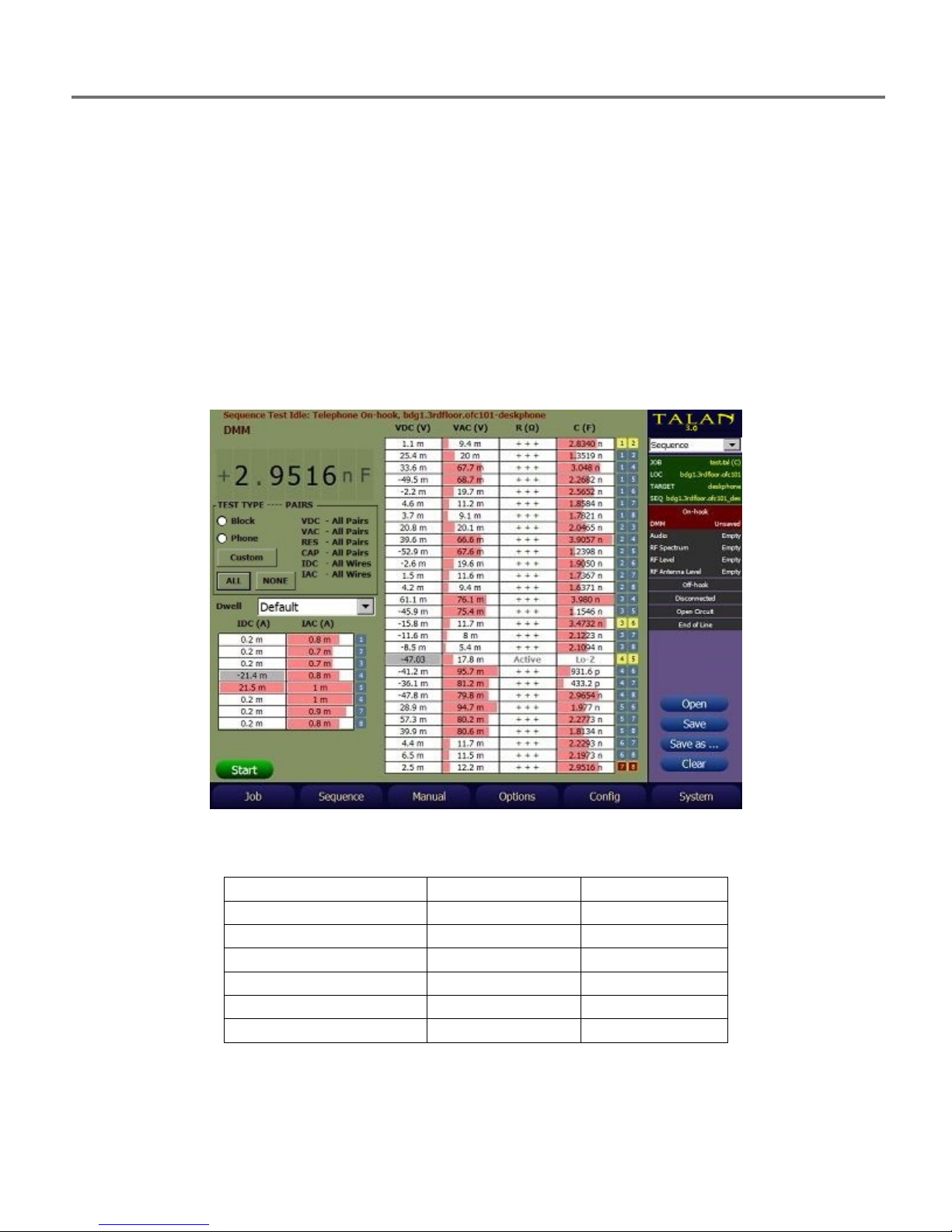
The example below shows a Samsung digital phone system that uses a 45-volt supply on the
main pair of 4:5. In this example, the balanced pairs are 1:2, 3:6, 4:5 and 7:8.
The balanced pairs should have the same capacitance values (2.97nF in this example) as
indicated for pairs 1:2, 3:6, and 7:8. The capacitance value of 4:5 is not measured because the
pair is active with voltage on the line.
There may be situations where signal conditions are such that a given test does not remain on
the pairs or wire long enough to be able to give a reliable reading. For these instances, the user
can change the Dwell time selection from Default to Extended.
The Dwell selection is available in the Manual DMM and Audio tests, as well as the Sequence
DMM and Audio tests.
While the Dwell selection is remembered and used when going between different test types
and test screens, it is NOT retained when the TALAN is powered off then back on.
37
Page 38

MANUAL TEST FUNCTIONS
DMM (Advanced Shield and EarthGround Testing)
TALAN 3.0 provides Manual DMM testing of the Phone / Line wires against either:
The Shield of an RJ45 cable plugged into the Phone or Line Jack of the TALAN
- or -
An additional wire fed into the EarthGround Green Banana Jack of the TALAN
Testing Phone / Line wires against the EarthGround jack gives a way to determine if a stray wire
in an Ethernet Junction box is being used as a tap or for some other illicit purpose.
To perform this testing, from the Manual DMM test page, press the Shield Earth button that
resides just to the right of the START button. This will bring up the following display:
The Shield and EarthGround testing interfaces are shown. The normal Test Options selection
for Pairs is not functional for Shield or EarthGround testing. However, there is an individual
selection for each now. This allows the testing event to be customized. The Wires To Test can
be customized through the drop down menu item individually for the Shield or the
EarthGround to All Available Wires, Selected Wire, or None.
Note: When selecting the Shield to do a specific test, the EarthGround selection will be forced
to None. Likewise, when selecting the EarthGround to do a specific test, the Shield selection
will be forced to None.
38
Page 39

MANUAL TEST FUNCTIONS
The same testing controls for Manual DMM is permitted for the Shield and EarthGround tests.
E.g. Selection of Tests, Range, Dwell, etc.
The right dashboard Connections display can be used to control the selections when the Wire
To Test is set to Selected Wire. The following figure shows a test of resistance with 265K
resistance between Wire 4 of a CAT6 cable plugged into the Phone jack and the Shield of the
CAT6 cable:
The DMM Measurements taken against Shield and EarthGround connections can be saved in a
TALAN Job file which can then be viewed on a PC running the TALAN Data Viewer V3.0 in the
Manual Test data section.
39
Page 40

MANUAL TEST FUNCTIONS
Audio
The Audio test provides for listening to both Digital and Analog Audio. Select the Audio option
from the Manual menu to access the Audio test screen.
After opening the Audio screen, there are several methods to select the desired pair.
Tap the desired pair listed (4:5 is shown on the test display)
Tap the Input portion of the Summary dashboard to bring up the Connection
dashboard.
Press the C button on the keypad to bring up the Connection dashboard.
In most cases the center pair should be selected (Pair 4:5).
When you have more than one pair, and you have Pairs in the Test Options dashboard set to
either All Pairs or Balanced Pairs, a test run will cycle through those pairs when you press Start.
Similar to the DMM tests, there will be times when you want to sit on the pairs and listen
longer than the normal default time. For those instances, the Dwell can be set to Extended.
40
Page 41

MANUAL TEST FUNCTIONS
To select the proper digital demodulation, you must specify the proper digital system. Press the
Digital button on the Audio dashboard to open the Digital Audio dashboard, and then select
Install to load the proper Digital system. You must select Upload to program the TALAN for this
system. It will take approximately 1 minute to upload the system demodulation program for a
particular digital system.
41
Page 42

MANUAL TEST FUNCTIONS
In the Digital Audio dashboard, Channels indicates which side of conversation is being
demodulated. Select Mixed in order to hear both sides of the phone conversation, Primary to
hear only the handset, or Secondary to select the audio coming from the switch. To listen to
normal analog audio, Digital Decode should be unselected.
The Codec indicates the type of modulation that is used. μ-law is used primarily in North
America and Japan while a-law is prominent in the rest of the world.
To adjust Volume and Gain Control, the controls are on the default audio dashboard. You can
access the Audio dashboard by pressing the A button, or by selecting the Audio button on the
Digital Audio dashboard.
42
Page 43

MANUAL TEST FUNCTIONS
For audio analysis, the Mute and Bandpass Filter should be off. Initially, start with the Volume
and Gain settings very low and increase as needed. If the Gain level is set too high, it will
overload the Automatic Gain Control Circuit and the audio board will basically turn off. Also,
care should be taken to avoid feedback with the phone system. It is recommended that
headphones be used with the TALAN to avoid feedback and to be non-alerting while testing.
When the set-up is performed properly, the user should be able to generate good audio
including Oscilloscope views of the digital audio as shown below. The example below shows a
typical dial tone signal on a single pair.
43
Page 44

MANUAL TEST FUNCTIONS
Note: in the example below, the Test Options dashboard was used to test all pairs for audio. In
this particular case, the cable that was tested was only a 2-wire system, but an 8 conductor Cat
5 cable was used in the system. Hence, any combination of 4 or 5 results in some audio because
the system is capable of demodulating the audio even if only ½ of the signal is present.
It is also interesting to note that the audio levels are basically the same for the combinations
that contain audio. This is because the strength of the digital system is not indicated through
the digital demodulation process. In other words, a weak digital signal and strong digital signal
will basically result in the same analog audio level after the demodulation.
44
Page 45

MANUAL TEST FUNCTIONS
Audio (Advanced Shield and EarthGround Testing)
TALAN 3.0 provides Manual Audio testing of the Phone / Line wires against either:
The Shield of an RJ45 cable plugged into the Phone or Line Jack of the TALAN
- or -
An additional wire fed into the EarthGround Green Banana Jack of the TALAN
Testing Phone / Line wires against the EarthGround jack gives a way to determine if a stray wire
in an Ethernet Junction box is being used as a tap or for some other other illicit purpose.
To perform this testing, from the Manual Audio test page, press the Shield Earth button that
resides just to the right of the START button. This will bring up the following display:
The Shield and EarthGround testing interfaces are shown. The normal Test Options selection
for Pairs is not functional for Shield or EarthGround testing. However, there is an individual
selection for each now. This allows the testing event to be customized. The Wires To Test can
be customized through the drop down menu item individually for the Shield or the
EarthGround to All Available Wires, Selected Wire, or None.
45
Page 46

MANUAL TEST FUNCTIONS
Note: When selecting the Shield to do a specific test, the EarthGround selection will be forced
to None. Likewise, when selecting the EarthGround to do a specific test, the Shield selection
will be forced to None.
The same testing controls for Manual Audio is permitted for the Shield and EarthGround tests.
E.g. Selection of Test Analog Audio, Test Digital Audio, Read DC, etc.
The right dashboard Connections display can be used to control the selections when the Wire
To Test is set to Selected Wire. The following figure shows a test of Analog Audio with a
speaker between Wire 4 of a CAT6 cable plugged into the Phone jack and the Shield of the
CAT6 cable:
The DMM Measurements taken against Shield and EarthGround connections can be saved in a
TALAN Job file which can then be viewed on a PC running the TALAN Data Viewer V3.0 in the
Manual Test data section.
46
Page 47

MANUAL TEST FUNCTIONS
Classify Pairs
When planning to test a telephone line, it is important to be able to identify the balanced pair
combinations. The TALAN provides some test functions that will assist in identifying which pair
combinations are the balanced pairs. This is very useful because for many testing functions it is sufficient
to only test the balanced pairs and to save time by NOT testing all of the odd pair combinations.
To classify the appropriate balanced pairs, press the F3 (Manual) button at the bottom of the screen and
select Classify Pairs.
To Run the pair classification test:
1. Ensure that the phone is disconnected and that the TALAN is only connected to the line that
goes to the switch.
2. Press the START button.
This test is a line impedance test that measures the coupling between balanced line pairs. The pair
combinations with the strongest bar graphs should be balanced pairs. In the example below, the
balanced pairs are clearly 1:2, 3:6, 4:5, and 7:8.
After reviewing the balanced line data, you should manually define the combinations of balanced pairs
by selecting them in the Define Connections dashboard. Tap the connector numbers that make up the
pair and select Add to define the pair as a balanced pair. Once the balanced pairs have been defined, all
other test screens will display the balanced pairs with a yellow background.
47
Page 48

MANUAL TEST FUNCTIONS
1 2 3 4 5 6 7 81 2 3 4 5 6 7 8
It is important to note that depending on the length of the cable and the type of cable, this test
will have varying results. It is intended only as a guide, and if the test does not result in
definitive results, the user can always simply look at the pair combinations within the cable
itself to determine proper pair combinations. Note: the plug shows the balanced pairs of 1:2,
3:6, 4:5 and 7:8.
It is also important to note that flat cables will have some interesting results. For example a 4
conductor flat cable will have strong coupling between all the pairs that are adjacent to each
other in the cable. For example: 1:2, 2:3, 3:4 will all have strong responses. The standard for flat
cable is that the center pair is the main pair and the outer pair is the secondary, therefore the
correct cable pairing for this situation is 2:3 and 1:4, and must be manually implemented.
In the example below, a six conductor flat cable is analyzed. In this case, adjacent conductors
always couple with each other as indicated by the test. However, the actual standard pairs are
defined from the inside out as 4:5, 3:6, and 2:7.
48
Page 49

MANUAL TEST FUNCTIONS
FDR Frequency Domain Reflectometer
The FDR (Frequency Domain Reflectometer) functions very similarly to a TDR (Time Domain
Reflectometer), however the FDR function provides similar results based on a different physics
principal.
To provide the best comparison of multiple pairs, the TALAN provides the ability to plot
multiple FDR traces on the same display.
The Distance and Gain can be adjusted using the on-screen controls. You must specify the
Measurement Units, the Velocity Coefficient, Gain and Distance, but you do NOT specify a pulse
width (as required with a TDR).
To get the range to any point simply tap on the screen and a blue vertical line will indicate the
range.
Furthermore, multiple FDR traces can be plotted on the same graph. In the example shown
below, all pair combinations were automatically acquired, however, only the main pairs are
being displayed. This is accomplished by tapping the desired pair for display using the stylus. In
this example, pair 4:5 is the main pair (shown in red) and is connected to the phone switch;
however pairs 1:2, 3:6, and 7:8 are not connected to the switch. These unused pairs are
terminated at the patch panel before the switch with a slightly shorter cable length.
Furthermore, the switch is located 169 ft from the TALAN, and the few spikes at very short
range are showing the short cable that is connected from the TALAN to the wall jack.
49
Page 50

MANUAL TEST FUNCTIONS
RF Analysis
RF analysis is broken into 3 testing functions:
1. RF Level
2. RF Spectrum
3. RF Antenna Level
The RF Level function is a broadband detector analysis that covers a frequency range to
600MHz, the RF Spectrum function is a spectrum analyzer function to 85 MHz and the RF
Antenna Level function is to be used with the supplied antennas to a frequency range of 8 GHz.
Broadband Line RF Level Analysis
Select the RF Level test to access the screen below.
In this screen, all pairs were tested for general broadband RF energy. As you can see from the
screen in this example, all pair combinations containing a 4 or 5 contain reasonable RF energy.
This is because pair 4:5 in this particular system is active and currently communicating with the
phone handset. The time level graph plots the changes in broadband level over time. In this
example, the data was captured by automatically switching through the pairs so the time graph
roughly reflects the same data as shown in the bar graph representation of each pair.
50
Page 51

MANUAL TEST FUNCTIONS
RF Spectrum Analysis
Select the RF Spectrum test function to access the RF spectrum analyzer. This mode is strictly
designed to analyze the RF spectrum of telephone wiring up to 85 MHz in a method very similar
to the OSCOR.
It is recommended that the desired pair is selected by first selecting the “Single pair” option
and then tapping the desired pair for analysis as indicated in the figure below.
The RF Spectrum Screen will be updated after the START button is pressed.
The + and – buttons are used to zoom into the spectrum and look at specific signals or portions
of the spectrum. This is accomplished by positioning the cursor with a stylus and then using the
+ and – to zoom in or out.
Sweep and Analyze Screens
The RF Spectrum Analyzer screen is divided into two sections, “Sweep” and “Analyze”. The
Sweep screen is the wider top window that shows the full spectrum to 85 MHz. The two
windows below the Sweep screen are the Analyze windows: the window on the left is the
frequency spectrum window, and the window on the right is the time domain window. The
time domain window is basically an oscilloscope view of the demodulated signal.
The main difference between the Sweep and Analyze modes is that the Sweep mode scans
across the entire frequency spectrum in 10 kHz steps, but the Analyze mode locks the receiver
to a fixed frequency so that a signal may be demodulated and listened to. Hence, if the Analyze
mode is selected, the Sweep window will not be updated as shown in the next figure.
51
Page 52

MANUAL TEST FUNCTIONS
Selecting and Analyzing a Signal
While in the Sweep screen you can select a signal by tapping on the Sweep window at the
desired frequency using the stylus. Then, simply press the Analyze button to go into the Analyze
mode. You may need to re-adjust the frequency by tapping the analyze screen at the
appropriate frequency location or turning the rotary dial to adjust the frequency.
Displaying Multiple Traces for Comparison
You can have the unit display multiple RF traces simultaneously. For example, it may be useful
to capture an RF trace of the main 4:5 pair as well as the other balanced pairs. This can be done
by classifying the balanced pairs and having the TALAN automatically capture these spectrum
traces or simply by manually selecting the pairs of interest and displaying the spectrum traces
simultaneously. In the figure below, combinations 1:2, 3:6, 4:5, and 7:8 have been captured and
are being shown. Pair 4:5 is the current active pair and shown in red.
52
Page 53

MANUAL TEST FUNCTIONS
RF Antenna Level
In this mode, the unit only takes data from the RF antenna port and displays a bar graph very
similar to a CPM-700 Broadband Detector but with the additional advantage of having the time
window to observe changes over time as the product is used as a broadband RF detector. It is
important to note that the frequency ranges of the supplied antennas are:
Whip Antenna: 10 MHz to 2 GHz
High Frequency Antenna: extends the range up to 8 GHz
The example below was taken with the whip antenna as the antenna was passed near a low
power transmitter. The peaks in the time level graph indicate when the antenna was closest to
the transmitter.
53
Page 54

MANUAL TEST FUNCTIONS
NLJD Line Non-Linear Junction Detection
The Non-Linear Junction Detector function is one of the most powerful tests in the TALAN. It is
very reliable for determining if there are additional electronics attached to a line. Additionally,
you can easily identify which conductors have the additional electronics, and you can identify
the connection as a series or parallel connection.
Furthermore, when testing a line for an NLJD response, you must consider that a strong 3rd
harmonic response is typically not the result of a corrosive line, rather it may be the result of
limiting diodes in a phone tap.
It is highly recommended that you only use the NLJD function on a dry line meaning the phone
should be disconnected and the line should be disconnected from the switch. Ideally, there
should be no electronics on the line. However, in the first example below, the line was still
connected to the switch, and it appears that there are electronics on many pairs, but if you look
closely, it is clear that the transmit power is turned off and therefore, the response that you are
seeing is merely the digital signals on the line that are in the frequency range of the NLJD
detection circuit. In other words, the indicated responses in the figure below are not threat
NLJD signals. You should always be careful when using the NLJD function to make sure that the
signals that you are detecting are not part of the phone system.
54
Page 55

MANUAL TEST FUNCTIONS
Amplifier
Tap to
line
Analyzing 2nd and 3rd Harmonic Results
In classic NLJD technology that is used for detecting bugging devices, a strong 2nd harmonic is
indication of an electronic device while a strong 3rd harmonic typically indicates a corrosive
false alarm junction. However, when using NLJD technology for looking for taps, you cannot
expect that a strong 3rd harmonic indicates a false corrosive junction. The reason is that many
telephone tap circuits rely on parallel diode limiting circuits. The figure below shows a portion
of a tap circuit that uses a transformer to isolate the tap electronics, a blocking capacitor to
isolate DC voltage (for a parallel tap), and 2 diodes to limit the input to the amplifier circuit.
These 2 diodes in parallel create an NLJD response that results in a strong 3rd harmonic
response.
The next two examples will show responses to this type of tap. In the figure below, there is a
parallel tap installed on an isolated 8 conductor line on pair 4:5. Again, you can see that every
pair with either a 4 or 5 has strong harmonic level (even though 4:5 indicates the strongest
response). It is also important to note that the transmit power is about 70% of maximum
power. The reason that the response is showing up on combinations of either 4 or 5 is that
there is sufficient power to get good response even though only 1 wire of the pair is connected
to the tap device.
To determine the proper pair with the tap, the transmit power is manually decreased until only
the true pair shows an NLJD response.
55
Page 56

MANUAL TEST FUNCTIONS
In this case, the Tx power was reduced to less than 10%, and hence, the parallel tap is clearly
being displayed only on pair 4:5.
In the next example, there is a serial tap only on conductor number 8. Therefore, only
combinations that contain conductor 8 will get a response.
56
Page 57

MANUAL TEST FUNCTIONS
In the next example below, there is an electret microphone that is placed on an unbalanced
pair combination of 1:3. You can see a strong 2nd harmonic response on many pair
combinations that contain 1 or 3, and also some response on the unbalanced 2:6 pair whose
conductors are balanced with 1 and 3. This is an excellent example of inductive coupling that
can occur in a telephone line.
By further reducing the transmit power, it is easy to see that the pair that is tapped is 1:3.
From studying these types of responses it is easy to quickly identify different types of taps.
57
Page 58

MANUAL TEST FUNCTIONS
VoIP (Overview, Connections, Mirroring…)
Voice over IP (VoIP) technology encodes speech for transmission over IP (internet protocol)
networks. TALAN has the ability to monitor IP packet traffic using its built-in network interface
card (NIC) and to display, analyze and save those packets to assess the threat of illicit VoIP
phone system intrusions. With the TALAN 3.0, VoIP Plus+ was added to help identify VoIP traffic
based upon characteristics of VoIP packets. VoIP Plus+ is intended for Ethernet type traffic, and
brings with it several features that normal Network Analyzers either cannot do, or can do with
great difficulty or extensive filtering.
To analyze VoIP traffic with either VoIP Analysis or with VoIP Plus+, the TALAN should be
connected via the TALAN network port (under the right grip) between the phone and the phone
system network. Some VoIP phone handsets have a non-switched internet port which can be
connected directly to the TALAN’s network port allowing the TALAN to see the VoIP traffic
between the phone and the network.
A common scenario is a phone with no extra port or a phone with a switched port allowing
network access but does NOT include the phone traffic. In these scenarios (no network port or
switched port that does not include phone traffic), the VoIP Test Adapter must be used in-line
with the phone network line (see diagram below).
Using an additional CAT5 cable (included), connect the VoIP Test Adapter in-line using the
PHONE and NETWORK ports on the test adapter. This allows normal phone activity to take
place. Using a 2nd additional CAT5 cable (also included), connect the TALAN network port
(under right grip) to either the Rx or Tx port on the test adapter to monitor either the
information being received (Rx) by the phone or transmitted (Tx) from the phone. The adapter
acts as a passive tap on 10/100 Mbps networks. If connected to a network that operates at
faster rates (1Gbps+), the tap is designed to force the network to auto-negotiate down to the
100Mbps rate compatible with TALAN.
Caution – Phones and PCs may auto-negotiate the physical hardware interface setup with the
router/switch/hub that they are connected to. Typically this only sets the speed, duplex, etc.,
but sometimes this also means they can swap the lines normally used for Rx and Tx. The way to
tell is to look at the Source IP Address. If the Source IP address is the IP address of the phone,
then you are on the Tx lines of the phone. If the DstIP address is the IP address of the phone,
then you are on the Rx lines of the Phone.
58
Page 59

MANUAL TEST FUNCTIONS
Notes:
- To connect the TALAN to Gigabit systems that will not auto-negotiate down to 100
Mbps, a third party switch could be used to provide a mirrored port at 100 Mbps while
not affecting the gigabit traffic.
- Disconnecting a VoIP phone to connect the VoIP Test Adapter will disrupt any active
network traffic on that line. Leaving a VoIP Test Adapter in place on a specific phone
line provides the capability to test the phone at any time without having to disrupt the
line. Additional VoIP Test Adapters can be purchased from REI.
- The VoIP Test Adapter (black box) is used to analyze VoIP traffic from a VoIP phone
using the TALAN’s Ethernet port. The VoIP Adapter Cable is used when performing
TALAN’s other test functions (DMM, Audio, FDR, RF Analysis, etc…) by inserting it
between the VoIP phone and the PHONE jack on the back of the TALAN.
Most VoIP phones and VoIP capable PCs are connected to a network using a General Switch, or
a Managed switch, as shown below:
59
Page 60

MANUAL TEST FUNCTIONS
Usage of the VoIP Test Adapter brings with it items that need to be noted:
- When using a PoE phone, if a specific VoIP Phone is suspected of sending audio data
when it is on-hook, then installing the VoIP Test Adapter will remove power from the
phone, which will interrupt the audio transfer in process, and possibly disconnect the
session, thereby alerting the intruder. For this case, if the phone is connected to a
managed switch, and you have the capability to configure port mirroring to an unused
port on that switch, this will not interrupt the audio transfer in process. Port Mirroring,
also known as SPAN (Switched Port ANalyzer), is a method of monitoring all network
traffic seen on one (or more) port(s) (the Monitored port), to another port (the Analysis
port). This is visualized in the following figure:
- This same “Mirrored Port” method can be used with VoIP Phones not using PoE or even
on PCs to see if they are passing audio using programs such as Skype.
- If the VoIP Phone is not using PoE, but has an external power supply, and it is in the
processing of sending audio, meaning, a connection is made and someone is “listening”
from another phone, then it is possible, with practice to connect the VoIP Test Adapter
and not lose the connection nor the audio transfer. This requires that the VoIP Test
Adapter already have one of the short CAT5 cables connected on the Network side of
the VoIP Test Adapter, and quickly remove the VoIP Phone’s cable from the router/wall,
and plug it into the Phone side of the VoIP Test Adapter, then plug the VoIP Test
Adapter Network cable back into the same physical port on the router/wall. This is
relying on TCP to maintain the connection after a less than a second data loss.
- Whereas it is possible to monitor more than one port via Port Mirroring (e.g. mirror
both VoIP Phones and the PC shown above), one should keep performance in mind. If
you mirror traffic from multiple ports, the mirrored traffic may exceed the capacity of
the TALAN. To help reduce the possibility of dropping packets in the TALAN, it is possible
to set up packet filters in the TALAN, see VoIP Plus+ for more information on how to
set/adjust Receive Filters.
60
Page 61

MANUAL TEST FUNCTIONS
- When the network administrator, or one of the technicians, is suspect in setting up a
VoIP phone for unauthorized audio broadcast, then the Port Mirroring method can still
be utilized. However, instead of modifying any settings in the suspect router/switch, a
router/switch that has already been setup for Port Mirroring can be utilized.
o Disconnect their router from the network
o Patch it through your router
o As shown below, the cable from the general switch that went to the LAN is now
connected to [My Switch], and [My Switch] is connected to the LAN. The middle
port shown would be set up with Port Mirroring, to monitor the port from the
General Switch:
The TALAN Ethernet Interface is set up so that it does not annunciate itself with the network
server, meaning, that the TALAN will not be detected by anything used to monitor network
access, including network monitoring packages such as wireshark or even the nework
administration / server software. However, the TALAN does work at the hardware layer so that
the when plugged into a switch or router, the hardware of that switch or router will make a
hardware level connection, but still is invisible to any other devices on the network. The
software and hardware in the TALAN are designed so that it will not transmit any packets of any
sort on the network. It is only a listening device so the network interface is non-alerting to
potential threats. This is a very big benefit when using the TALAN instead of a laptop to look for
illicit traffic. Laptops will be seen on the network by system administrators, whereas the TALAN
will not be visible on the network.
61
Page 62

MANUAL TEST FUNCTIONS
VoIP Plus+ (Advanced Detection and Analysis)
When the TALAN 3.0 Hardware is installed, the TALAN provides a VoIP Plus+ Analysis intended
to make detection of VoIP traffic easier and more reliable. To activate the VoIP Plus+ feature,
select VoIP Plus+ from the F3 (Manual) menu. If the TALAN 3.0 Hardware is not installed you
will see the following screen:
Selecting Continue permits the Control Interface to be displayed, but it is non-functional in that
it will not receive packets nor load and run files. The figure below shows the fully functional
TALAN VoIP Plus+ Control interface:.
62
Page 63

MANUAL TEST FUNCTIONS
VoIP Plus+ has a lot of features that can be selected, but, in the default state it is meant to
simply collect the Ethernet Packet data and determine if there is a probability of VoIP, or not.
Most of the time, the user will simply select Start Receiving, and view the Network Streams at
the top and the Frequency graph at the bottom of the screen. When Start Receiving is pressed,
VoIP Plus+ starts processing packets it sees on the Ethernet.
The above figure shows a typical VoIP signature when the TALAN is connected between a VoIP
Phone and it’s router using the VoIP Test Adapter. The type of data to show in the list is set to
NetworkStreams. This is the default.
The list of packets collected can be viewed by selecting the PacketList above NetworkStreams.
However, due to processing overhead, it is advised to try to do all of the analysis using
NetworkStreams unless the intent is to isolate a specific packet in time. The number of packets
stored for view in the PacketList is also very limited, and old packets are thrown out over time.
The type of graph shown at the bottom of the screen is set to the default Frequency graph. The
data shown can be set to “Average” or “Peak” or “Current”. Average is the default. Peak is very
useful in finding something when left running over night. Current is helpful in showing exactly
what is happening right now.
63
Page 64

MANUAL TEST FUNCTIONS
The data to show in the graph can be set to PacketHits (the count of packets over time), or
Payload (the size of data in the packets over time). The time duration of the displayed data for
PacketHits and Payload can be adjusted using the ++, +, -, and — buttons to the left of the
graph. Below are two screens showing PacketHits of the same 50Hz data stream, shown at the
maximum 10s time frame, and also the Payload showing the default 2s time frame.
Look at the original VoIP Plus+ Control interface. It shows the main two analysis methods of
Start Receiving and Load File.
Start Receiving performs analysis of actual network traffic happening right now.
Load File performs analysis of data that has already been collected in a file. The file types
accepted are standard PCAP files.
64
Page 65

MANUAL TEST FUNCTIONS
PCAP files have the same format as files collected by other known network analyzers such as
Wireshark or Cain & Abel. This also means that the TALAN can analyze PCAP files captured by
other network analyzers, place them on the root folder of a USB memory stick, install it into the
TALAN, and then select Load File, Select the file to run, then select Run File. The same functions
that can be used in real time can also be used when running a loaded file. The file will run until
all packets are processed, or select Stop File to stop at any time. The TALAN can save packets
that are being received to a file. First, Start Receiving, then select the Capture button to start
capturing packets. Then when ready to stop and save the captured files, select Stop Capturing,
then Save To File. If a USB memory stick is installed, it will be saved to the USB and the file
name will be shown. If the USB memory stick is not installed, the file will be saved to the
Compact Flash with the shown name.
There are two options for running a file. When you have a file loaded, ready to run, the options
QuickScan and Loop appear, the default is QuickScan enabled and Loop disabled.
QuickScan permits the TALAN to process through the packets as fast as possible. This is very
helpful when data has been collected for a long period of time and it is desireable to get
through non-VoIP traffic as fast as possible without wasting time in order to get to the real
VoIP traffic. Disabling QuickScan will run the file analysis at the rate at which packets were
received.
Loop will continue to run through this file over and over again. Good for demonstrations.
65
Page 66

MANUAL TEST FUNCTIONS
When Receiving or Running a file, all of the analysis is performed on all of the packets received
or run from the file. To help narrow down details on a specific stream, select a specific stream
by tapping it in the NetworkStreams list. Below is the result of selecting the first
NetworkStream. There is a new status window in the lower right of the screen, showing more
details about this specific stream. Including:
From – Identifies the Source IP address and the Source Port
To – Identifies the destination IP address and the destination Port
Elapsed – identifies the elapsed time this receive has been running.
AvgIPG – identifies the Average Inter Packet Gap, showing the average time between
subsequent packets in this stream, and the calculated frequency of this specific streams
packet arrivals in Hz (in parenthesis).
For this next screen, Listen was also selected, showing an audio graph in the upper right
window of the decoded audio from this network stream.
The Gain slider in the right dashboard adjusts visually the level in the audio graph. The Volume
slider in the right dashboard adjusts the audible level in the speaker/headphone of the
recovered audio.
The type of audio can be decoded as if it were either G.711ulaw, or G.711alaw, or raw 16 bit
PCM audio or raw 8 bit PCM audio using the decode section in the lower right details
selections. Sometimes using 8 bit PCM on data that is of a different format is sufficient to listen
to in order to know that when things are silent, there is a given sound in the audio, and when
there is speech, there is a definite change in that recovered audio sound.
An Audio Filter can be enabled to improve the sound of the audio, if it is indeed audio.
66
Page 67

MANUAL TEST FUNCTIONS
Up to this point, all data has been collected, and processed and shown in both the NetworkStreams
list and in the Frequency graph. Look at the original VoIP Plus+ Control interface. It shows filter
selections in the upper right of the display that can be enabled to limit the type of packets analyzed.
The receive filter options are:
All (Default) – All receive or file data is processed and included in the NetworkStreams list and
Frequency graph, unless customized by other settings.
Ignore ARPs – When enabled, ARPs will not be included in the analysis. Windows 8 and later PCs
will search the network for connected devices. This reduces that influence on the data.
Suspect –When enabled, analysis focuses on packets that use ports that have been used in the
past for malicious activity.
NotEthernet2 – When enabled, analysis focuses on packets that are not classified as
“Ethernet2”, the latest standard. While it is the most used standard now, there are many
business networks that still have Novell, SNAP, and/or 802.3Raw. All three of these should not
be present on modern networks. Yet they can exist and modern Network Analyzers might not
see them because newer network cards in PCs today are not set up to receive them. SNAP and
802.3Raw do not require a server, but have been used for tunneling or unauthorized VPNs in
the past, and do reside on networks today, such as an iDevice tunnel in to a VPN and would go
unnoticed by modern network analyzers and therefore might not be seen by network
administrators.
VoIPPorts – When enabled, analysis is performed on packets that use known VoIP Ports only.
This can be done in other Network Analyzer programs, but, it is a LONG list of ports that are
known VoIP ports and takes a lot of time to set up the filter manually.
HTTP (80, 443) – This is reliant on checking VoIP Ports, you can further isolate the VoIP Ports by
specifically leaving out 80 and 443 data. These are typically used for HTTP traffic (meaning the
web page itself). BUT, google and others have been experimenting with a QUIC protocol for
VoIP based on UDP that is sent via normal HTTP ports 80/443. This permits you to find those
specifically.
67
Page 68

MANUAL TEST FUNCTIONS
Here is a screen shot of a capture collecting PC traffic that has a lot of YouTube downloads
running, but there is no VoIP traffic. This is evident by the fact that the Frequency graph is very
erratic. There is no fundamental frequency and there are no repeating harmonics.
Here are two screen shots of what it looks like to have VoIP on a mirrored port. Remember, a
mirrored port on one device will show both inbound and outbound traffic. Meaning, it will
include both the Tx audio and the Rx audio. The screen shot on the left shows the two 33Hz
streams, and the resultant Frequency graph due to rate of the two streams not exactly in phase
at exactly 33Hz. The screen shot on the right shows the individual selected 33Hz stream. Notice
the difference in the two frequency graphs. Neither should be relied on to determine solely if it
is VoIP, but both are indicative of needing further investigation.
68
Page 69

MANUAL TEST FUNCTIONS
VoIP Analysis
The TALAN provides a VoIP Analysis interface that does not require the TALAN 3.0 Hardware.
To activate the VoIP packet analyzer select VoIP Analysis from the F3 (Manual) menu and then
press START. The TALAN VoIP Analyzer interface below will appear.
Once the TALAN is correctly attached to the VoIP network, the VoIP traffic (IP packets) can then
be collected, displayed, and analyzed by the TALAN VoIP Analyzer software.
69
Page 70

MANUAL TEST FUNCTIONS
Interface
Function
FileStart Trace or Traffic light icon
Start data collection
FileStop Trace or Stop sign icon
Stop data collection
Details Tab
View highlighted packet details
Stats Tab
View overall collection statistics
FileExport
Save collected data to file on USB/CF
FileClear
Clear collected data from memory
FileProperties
Access setup and filter definitions
FileEnable Filtering
Apply defined filter to new collection
FileClose
Close Analyzer program
Close icon [x]
Close Analyzer program
To access the functionality of the VoIP Analyzer, do the following:
Features of the TALAN VoIP Analyzer include:
displaying the source/destination MAC addresses, type of packet (ARP, TCP,
UDP), and source/destination IP addresses
calculating statistics (Stats tab) for each collection: total number of packets
collected, total average rate for all packets, running average rate for the last 5
seconds, peak 5 seconds average rate, & run time
allowing the user to setup custom filters to determine the type of packet
captures (e.g. only to/from specific sources)
providing for the export of packet files in text format or in WinPCap format for
import into a PC-based network packet analyzer, such as WireShark or Cain &
Abel
70
Page 71

MANUAL TEST FUNCTIONS
It is highly recommended
that the rotary dial be used
to adjust the power level of
the Line bias function. The
rotary dial provides a much
finer control, while the
stylus may provide quick,
large, jumps in voltage. You
should be careful not to put
too much voltage on a line.
Line Bias
The TALAN provides the ability to put a voltage bias on the line to enhance other types of
testing. This line bias voltage can range up to +/- 80 volts DC. TALAN can also provide AC bias
ranging from 10 Hz to 300 Hz.
Application of a line bias should only be performed on an isolated line that is not connected to
a switch.
By placing voltage on a line, you may power an electret microphone or provide power to a tap
to increase the probability of detection.
To activate line bias function, press the B button to access the following dashboard.
71
Page 72

MANUAL TEST FUNCTIONS
A/B Comparison
The TALAN is equipped to evaluate the results from multiple tests by comparing a live test
against a known good reference. The Compare dashboard can be accessed from either the
dropdown list or from the Compare button on the Test Options dashboard.
During any test mode, the results are saved in the A or “Live” position. They can then be
compared to a previous test or reference file loaded into the B or “Ref” position. All TALAN
Test functions can be compared using this A/B Comparison mode, however, only an FDR
example is provided in this manual as an example.
72
Page 73

MANUAL TEST FUNCTIONS
Live Data Selected
Comparison of “Live” and Known Good Reference
Reference Data Selected
The first image below shows an FDR test for the “Live” position. The second image shows a
known good FDR test on a similar line in the “Ref” position.
Finally, we see the comparison of the two tests on the same screen which shows a fault on the
“Live” line at approximately 96 feet.
73
Page 74

HARMONIC LOCATOR PROBE: LINE TRACING AND TAP DETECTION
HARMONIC LOCATOR PROBE: LINE TRACING AND TAP DETECTION
The Harmonic Locator Probe provides two basic capabilities:
1. An RF Line Tracer that operates at 225 kHz,
2. A harmonic detector to locate the existence of an electronic tap.
This system consists of a Non-Linear Junction Detector in which the main TALAN unit provides
the transmit function, and the hand-held locator probe provides the receive function.
Basic procedure is the following:
1. Connect the main TALAN unit to an isolated dry line without the phone or the switch
connected to the line.
2. Then select Line tracing from the Manual menu and adjust the transmit power level
using the stylus.
3. Using the Connections dashboard: select a wire pair that includes the conductor under
test and an unbalanced partner wire. The figure below shows a test of wire #4 with wire
#8 selected instead of the balanced partner (wire #5).
The best result is achieved when a single conductor is traced rather than a balanced pair
(this is because in a balanced pair, there is very little leakage, and the coupling between
the pair minimizes the ability to trace the wire.)
4. Turn on the Harmonic Locator Probe (HLP).
5. Test the locator probe by passing it over the wire to be traced.
74
Page 75

HARMONIC LOCATOR PROBE: LINE TRACING AND TAP DETECTION
For long runs of wire, it may be necessary to increase the transmit power as you trace farther
and farther from the main TALAN unit.
Warning: The tracing function should only be performed on a completely isolated line. It is
possible that the transmit power could possibly damage the switch. Secondly, the switch will be
attempting to communicate with a phone unit and may be communicating information in the
same frequency range as the receive function and therefore causing false detections.
75
Page 76

HARMONIC LOCATOR PROBE: LINE TRACING AND TAP DETECTION
3. Low Battery
Indicator
1. Fundamental
Receive
Signal
Strength
Indicator
2. 2nd Harmonic
Receive Signal
Strength
Indicator
When doing a counter surveillance investigation, it is important to analyze all of the wiring in
the environment to ensure that building wiring is not being utilized to transport audio or video
information. This wiring may include but is not limited to telephone wiring, LAN wiring, security
system or access control wiring, intercom speaker wiring, heating and cooling wiring, etc… The
HLP is an ideal tool to work with the TALAN to track miscellaneous wiring and/or identify the
location of a semiconductor device on the wire.
WARNING: Care should be taken when tracing wires to ensure that the Locator Probe
never comes in contact with high voltage wiring.
HLP Locator Probe Display
Figure 1: Front Panel Indicators
Please refer to Figure 1 for the following function descriptions. NOTE: The indicators
are shown as they would be seen in a normal operating condition.
1. The Green LEDs are used to show the relative Received Signal Strength Indication (RSSI) of
the 225kHz injected onto the wire to be traced.
2. The Red LEDs are used to show the relative RSSI of 450kHz. This frequency indicates the
presence of a semiconductor. The injected 225kHz from the TALAN is sent into the wire and
the generated harmonic is being re-radiated.
3. The LOW BATTERY indicator is lit when the 9V battery gets down to 5.8V.
76
Page 77

HARMONIC LOCATOR PROBE: LINE TRACING AND TAP DETECTION
HLP Controls
POWER – The POWER button serves two purposes: Turn power off/on or
return to normal operation.
UP – Used to increase the volume.
MODE – The MODE button is used to select mode of operation
DOWN - Used to decrease the volume.
Figure 2: Control Buttons
HLP Modes of Operation
The Harmonic Locator Probe (HLP) has three operation modes (Combination Mode, Tracing
Mode, and Device Detection Mode) detailed below:
1. Combination Mode
There is a combination mode that the unit defaults to upon the first time
power is applied. In this mode, the receiver will oscillate between
TRACING and DEVICE DETECTION. Each column will change accordingly
to the RSSI for that frequency. In this example, both the fundamental
(225kHz) used for line tracing and the secondary (450kHz) have a similar
RSSI level. This indication is typical of a situation where the HLP is close
to a semiconductor on the line of interest. See Figure 3. You will also be
able to hear the audio tone if the user chooses to enable it on the TALAN.
Figure 3: Combination MODE locating a Semiconductor
If there is no semiconductor or if you are too far away from the
semiconductor (in the combination mode), then the red LEDs will indicate
a minimum RSSI. See Figure 4.
Figure 4: Combination MODE while only tracing
77
Page 78

HARMONIC LOCATOR PROBE: LINE TRACING AND TAP DETECTION
2. Tracing Mode
The Tracing Mode utilizes a 225kHz signal (with selectable audio
modulation) from the TALAN to be injected into the wire to be traced.
As you trace the wire, the green RSSI indicator LEDs should increase in
number and the audio tone should be heard when the antenna is
pointed in the direction of the traced wire and within close proximity.
See Figure 5. Typically, you will hear the tone before you will see a
visual indication of close proximity to the wire being traced.
Figure 5: Tracing Mode
3. Device Detection Mode
The Device Detection Mode utilizes the injected 225kHz signal from the
TALAN. As you trace the wire, the red RSSI indicator LEDs (indicating
the presence of the 450kHz 2nd harmonic) should increase in number
when the antenna is pointed in the direction of the device and within
close proximity.
Figure 6: Device Detection Mode
78
Page 79

HARMONIC LOCATOR PROBE: LINE TRACING AND TAP DETECTION
Service Routines
The Harmonic Locator Probe has two service routines described below:
1. Volume
2. Mode
1. Volume
The volume can be changed by pressing the UP or DOWN button.
The green LEDs will indicate the relative volume level.
When finished changing the volume, pressing the POWER button will
return the user back to normal operation. Otherwise, the unit will
return to normal operation automatically after a preset timeout occurs.
Figure 7: Volume Control Display
2. Mode
If the user presses the MODE button, one of these modes can be selected.
Figure 8: COMBO Figure 9: TRACE Figure 10: DEVICE DETECT
Initially, the first press will initiate a lamp-test of the current operational mode.
Subsequent MODE button presses will sequence through these displays. When the
selected operation is obtained, pressing the POWER button will return the user back to
normal operation. Otherwise, the unit will return to normal operation automatically
after a preset timeout occurs.
79
Page 80

HARMONIC LOCATOR PROBE: LINE TRACING AND TAP DETECTION
Misc. Displays
Startup
When the user first puts in a battery or turns the unit on, there will be a brief period
(approximately 2 seconds) where the unit goes through the calibration routine. This is used
to sample the current ambient noise floor and is used to establish the proper operation of
the RSSI display. During this process the user will notice the bottom green and red LED
oscillating back and forth.
Low Battery Condition
If the 9V battery ever gets below 5.8V, the Low Battery Indicator (LBI)
in the top center will glow red. See Figure 11.
Figure 11: Low Battery Condition
HLP Battery Compartment
Figure 12: Battery Compartment
The power source is a 9V battery. There is a
sliding door that is used to retain the battery.
See Figure 12.
80
Page 81

HARMONIC LOCATOR PROBE: LINE TRACING AND TAP DETECTION
HLP Headphone Jack
The headphone jack on the left side of the unit, see
Figure 13, uses a standard mono 3.5mm plug.
Figure 13: Headphone Jack
81
Page 82

TALAN SPECIFICATIONS
TALAN SPECIFICATIONS
CONTROL SYSTEM
Primary Computer: 32 bit RISC processor, 520 MHz
Internal Memory: 64 MB SDRAM (OS), 64 MB Flash
External Memory: Compact Flash Type III,
USB mass storage
DIGITAL I/O
Network: 10/100 Ethernet Controller for IP Packet
Detection
USB: USB Device (A Type) supports external
keyboard, mouse, and USB mass storage device; USB
Host (B type) for future use.
ANALOG I/O
Headphone Output: 3.5 mm connector
Microphone Input: 3.5 mm input
USER INTERFACE
Hard Keys: 6 Soft Menu Keys, 5 Button Quadrant
Navigation & other dedicated keys
Encoder: High-Resolution Optical Encoder
Integrated Touch Screen with Stylus
Test Inputs:
Dual MOD8: Supports 2, 4, 6, & 8 wire
Modular Phone Jacks with Shield
(With TALAN 3.0)
Banana Type: Standard sleeved sockets:
Ring, Tip, and Earth
SMB RF Input: RF/Antenna Connection to
8 GHz Broadband Detector
Expansion Port: Supports communication
and measurement for use
with future accessories
All Inputs Electrically Isolated
RF SYSTEM
Spectrum Analyzer:
Dual Conversion, Super-Heterodyne Receiver
Frequency Range: 30 kHz to 85 MHz
Sweep Time: 2 Seconds
Step Size: 1 kHz
Bandwidth: 18 kHz
Sensitivity: -100 dBm
Broadband Detector:
RF SMB Input: 100 kHz to 8 GHz
Line Level Test: 100 kHz to 600 MHz
Sensitivity: -65 dBm
DIGITAL MULTIMETER
Quick Response Auto-Ranging: 500msec Sample Rate
AC/DC Volts: 0 to 250V Maximum
AC/DC Current: 0 to 300mA Maximum
Resistance: 0 to 42MΩ
Capacitance: 50pF to 40µF
BIAS GENERATOR
Optically Isolated, Direct Digital Control: High voltage
DAC
Output Ceiling: ±80V
Output Ceiling (Shield): ±65VDC, ±33VAC
Modulation: Fixed voltage, or variable rate Sine
wave (10 Hz – 300 Hz)
AUDIO
Audio Bandwidth: 20 Hz – 20 kHz
Gain: Up to 80 dB total system gain
AGC: Digitally Controlled Automatic Gain
Filter: Analog Voice band filter (300 Hz to 3 kHz)
POWER SYSTEM
External Input: 15VDC @3A
Universal Power Supply: 100-240VAC, 50-60Hz
Removable Battery: Rechargeable Lithium ion,
4-hour runtime (typical)
MECHANICAL
Dimensions: 10.0 in x 12.9 in x 2.7 in
(25.4 cm x 32.8 cm x 6.9 cm)
Weight with Battery: 6 lbs (2.7 kg)
Case Dimensions: 5.4 in x 14.9 in x 19.5 in
(13.7 cm x 37.8 cm x 49.5 cm)
Loaded Case Weight: 19.0 lbs (7.1 kg)
Operating Temperature: 0°C to +50°C
HARMONIC LOCATOR PROBE
Operational Frequency: 225 kHz & 450 kHz
Antenna Type: Balanced Loopstick
Headphone Audio Output: 16Ω, 105dB SPL limited
Battery: 9V Alkaline
Run-Time: 10 hours average, 22 hours (headphones)
Size: 17.5 in x 1.5 in (44.45 cm x 3.8 cm) stored
63.75 in x 1.5 in (162 cm x 3.8 cm) fully extended
Weight: 1 lbs (.5 kg)
82
 Loading...