

Page 1
Page 2
Page 3
Page 4

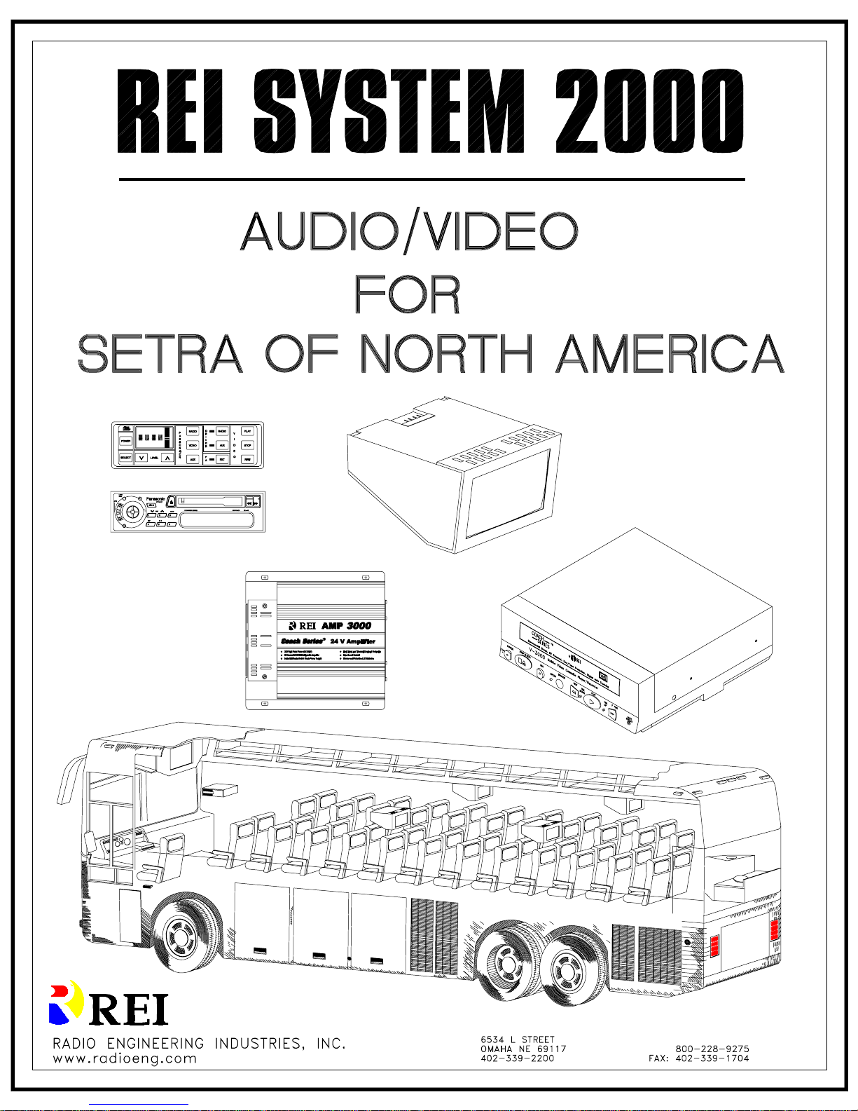
System 2000
Overview:
The System 2000 is a proven generation of Audio/Video entertainment
designed exclusively for tour buses.
The complete system incorporates:
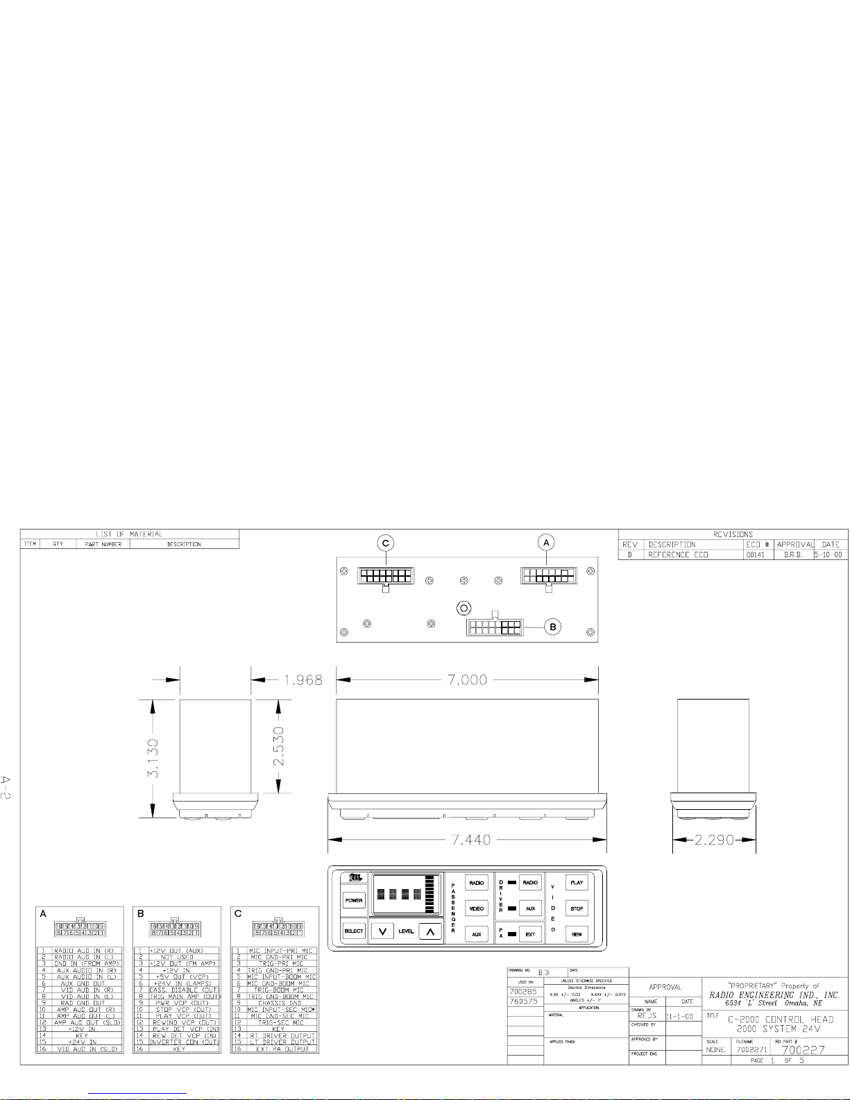
• A state of the art digital Audio Control Unit that incorporates advanced
digital design for enhanced reliability and complete centralized system
control. The Control Unit 2000 allows the operator to control up to three
audio selections, allowing custom tailoring of each channel’s sound
quality. There are three microphone inputs for the Public Address system,
which is switchable between internal and external speakers. The unit
contains a separate Video Section for controlling the VCR. It also allows
the driver to control his own separate audio selections. The Control Head
is housed in a shallow DIN-E chassis that allows ease and flexibility of
installation.
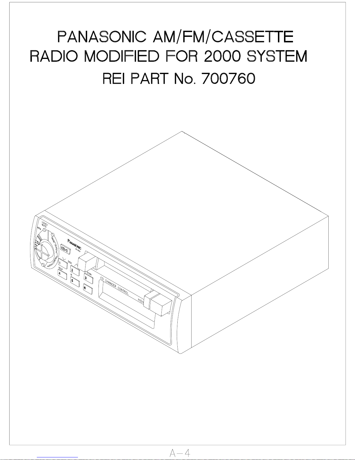
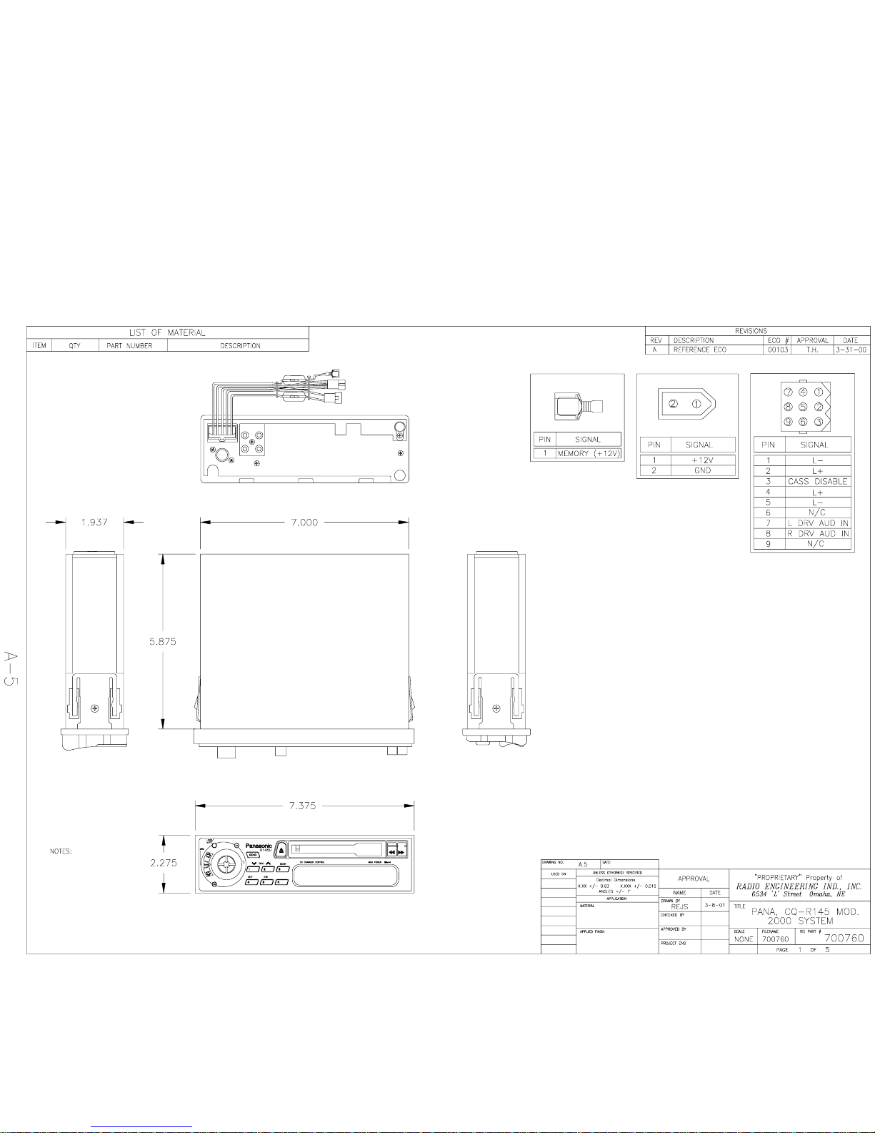
• A specifically designed 100-watt RMS per channel amplifier, capable of
driving up to twenty-six, four ohm speakers.
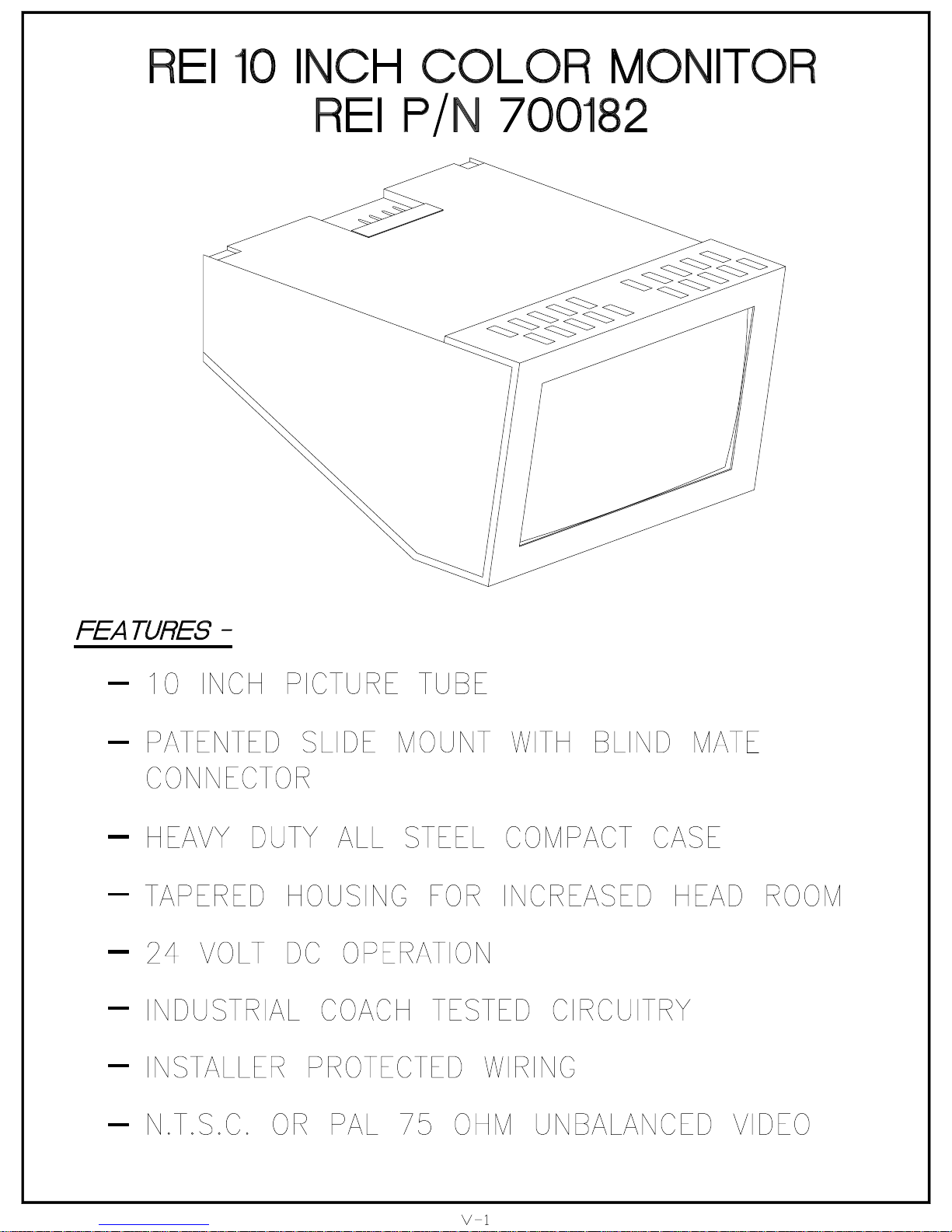
• Up to six, custom designed 10-inch color monitors, which incorporate a
patented, anti-theft locking slide mount. This design makes installation
and removal very easy. In conjunction with the Video system, there is a
specially modified VHS video cassette recorder that allows the operator
convenient control over its functions.
Individual seat audio option. Allows each passenger to choose between
•
up to seven channels of stereo audio and one video audio channel.
Allows individual volume control of each channel.
i
Page 5
Page 6
Page 7

Page 8
Page 9

Page 10
Page 11
Page 12
Page 13
Page 14
Page 15
Page 16
Page 17
Page 18
Page 19
Page 20
Page 21
Page 22
Page 23
Page 24
Page 25
Page 26
Page 27
Page 28
Page 29
Page 30
Page 31

Page 32

Page 33

Page 34

Page 35

Page 36

Page 37

Page 38

Page 39

Page 40

Page 41

Page 42

Page 43

Page 44

Page 45

Page 46

Page 47

Page 48

Page 49

Page 50

Page 51

Page 52

Page 53

Page 54

Page 55

Page 56

Page 57

Page 58

Page 59

Page 60

Page 61

Page 62

Page 63

Page 64

Page 65

Page 66

Page 67

Page 68

Page 69

Page 70

Page 71

Page 72

Page 73

Page 74

MICROPHONE EXTENSION OPTIONS
REI P/N LENGTH
510549 2 FT.
510774 3 FT.
510244 10 FT.
510520 20 FT.
510246 50 FT.
510886 60 FT.
MIC JACK OPTION (SURFACE MOUNT)
REI P/N LENGTH
510095 1 FT.
510049 4 FT.
COAX CABLE OPTIONS (BNC/BNC)
REI P/N LENGTH
511253 3 FT.
510406 7 FT.
510443 10 FT.
510690 12 FT.
511159 14 FT.
511062 15 FT.
510407 20 FT.
510414 24 FT.
511160 27 FT.
510928 33 FT.
510929 44 FT.
POWER CABLE OPTIONS (CINCH RECEPTACLE)
REI P/N LENGTH
510497 1 FT.
511024 1 FT.
510737 2 FT.
511167 2 FT.
510743 3 FT.
510738 4 FT.
511048 10 FT.
510689 15 FT.
511056 15 FT.
510688 25 FT.
511510 30 FT.
510686 37 FT.
510687 49 FT.
O-30
Page 75

Page 76

System 2000 Troubleshooting Chart
- Audio -
PROBLEM POSSIBLE CAUSE CHECK / SOLUTION
No audio, all channels.
No audio on Radio, Auxiliary,
Video, or PA.
No power to amplifier
Overload condition. Check 2 and 10 amp circuit breaker
Defective or improperly
Volume level on Control
Head (700227) set to
minimum
(700189 / 700511)
connected Amplifier
(700189 / 700511).
Adjust volume level with the
UP / DOWN arrow buttons on the
Control Head to a comfortable
listening level.
Verify power connections and any
external current protection devices;
fuses or circuit breakers.
located on the front of the amp.
Reset if tripped.
If tripped, verify speaker impedance
in case of shorted speaker.
If the Control Head (700227) turns
on, and all other connections are
correct, and the red power LED (on
the front of the Amp) does not light,
repair or replace AMP.
Defective or improperly
connected Control Head
(700227). Control Head does
not turn on when it's power
button is depressed.
Form: 640188 TS-1
Check (510566) cable connection
from Amplifier (700189 / 700511) to
the Control Head (700227). If all
connections are correct, repair or
replace Control Head.
Page 77

Audio on only one side of coach,
right or left. Other side functions
correctly.
Defective or improperly
installed audio cable
(510566) from Control Head
(700227) to the Amplifier
(700189 / 700511).
Check audio RCA connections on
the Amplifier (labeled Inputs Right
and Left). Verify plugs are seated
properly. Check Right and Left RCA
audio connections at the rear of the
Control Head (700227) labeled Amp
Audio Out #32. Verify connections.
Reverse Right and Left RCA audio
cables, at the Amplifier. If audio
changes to other side of coach
proceed to next check, If not go to
Amplifier Possible Cause.
Reverse Right and left RCA audio
cables at the rear of the Control
Head. If the audio remains
unchanged, repair or replace the
Control Head to Amplifier cable
(510566). If the audio changes to the
other side go to Control Head
Possible Cause.
Amplifier (700189 / 700511)
Defective or speaker
problem.
If reversing audio RCA cables at the
Amplifier (700189 / 700511) results
in no change, check speaker
connections (reverse connections left
for right). If still no change, repair or
replace Amplifier (700189 / 700511).
Control Head (700227)
defective.
If connections and Amplifier are
checked, as previously indicated,
repair or replace Control Head.
Form: 640188 TS-2
Page 78

No VCP audio, all other channels
operate correctly.
Dirty Audio Heads in the
VCP or bad Video Tape
Try playing a different Video tape.
Clean the VCP's heads with a high
quality wet cleaning tape.
VCP connections; Cable
(510575), power.
Does VCP have power? If not, check
power connections at the rear of the
VCP, and at the Video Relay. Make
certain Control Head (700227) is in
the VID mode. Repair or replace
Video Control Cable (510575).
Defective VCP. If possible remove unit and bench
test. Connect the unit to a monitor
that has Video and Audio inputs
using the VCP's Video and Audio
outputs. If previous checks do not
solve the problem, repair or replace
VCP.
Improperly connected or
defective Control Head
(700227)
Check Cable (510575) connection at
the rear of the Control Head, labeled
VCP #18. If connections appear
good and problem is not in the VCP,
repair or replace the Control Head
(700227)
Form: 640188 TS-3
Page 79

No Radio audio, (one or both sides
of coach) all other channels operate
correctly.
Improperly connected or
defective Radio.
Check power to the Radio. Radio
must be turned on to operate.
Control Head (700227) must be in
the RAD mode
Check RCA connections from the
Radio to the Control Head, Labeled
RADIO-AUD OUT #31 to RADIO AUD IN #31.
If Radio Audio is present only on
one side of the coach (other channels
operate correctly) reverse the RCA
connectors, on the rear of the Radio.
If the audio switches sides, repair or
replace the Radio. If the audio does
not switch sides, repair or replace the
Control Head (700227).
Defective Control Head
(700227).
Verify that the Control Head is
turned on and in the RAD mode.
Verify that the Volume is not set to
minimum. Check if Radio audio is
present on the Driver's speakers. If
so and all other checks are OK,
repair or replace the Control Head
(700227).
Form: 640188 TS-4
Page 80

No PA Audio. All other Channels
operate correctly.
Defective microphone. If possible, try a different
microphone in the same location. If
the different mic works, repair or
replace the microphone. If another
mic is not available, plug the
microphone into another Mic input.
If mic works in another location
continue with the following checks.
If it still does not function, repair or
replace microphone.
Defective cable. Check continuity on Microphone
cable with continuity tester (meter).
If a connection shows open replace,
or repair, cable.
Defective Control Head
(700227).
If replacing the Microphone, and
checking cable continuity has no
effect, repair or replace Control Head
(700227).
Form: 640188 TS-5
Page 81

No Driver's Audio. All other
functions operate correctly.
Defective, or improperly
wired Driver's speakers.
Check connections at the Control
Head and the Driver's speakers
(labeled DRIVER SPEAKER #35) at
the rear of the Control Head. Repair
or replace cable if defective.
Check Driver's Speakers and verify
they are operational. Replace if
defective.
Defective or improperly
operated Control Head
(700227).
Verify that the Driver's speakers are
enabled, by the Control Head. The
green LED, next to the RADIO
button in the DRIVER section,
should be illuminated.
Verify that the Radio plays over the
Passenger's speaker. If so, replace or
repair the Control Head (700227). If
not, proceed to Radio check.
Defective or improperly
operated Radio.
Check that the Radio volume control
(used to set the Driver's audio level)
is set to a normal listening level.
Verify that the Radio audio plays
over the Passenger 's speakers. If not
replace or repair the Radio.
Form: 640188 TS-6
Page 82

System 2000 Troubleshooting Chart
-Video -
PROBLEM POSSIBLE CAUSE CHECK / SOLUTION
No power, all Monitors. Monitors
blank, green LED on the rear panel
off.
No power to Video relay, or
Defective Video relay Activate the Video System via the
Defective or improperly
Video System not
activated.
wired incorrectly.
wired Control Head
(700227)
Power wire from Video relay
to monitors defective
Activate the Video system via the
button labeled VIDEO on the
Control Head (700227). Display will
indicate "VID".
Verify power connections to relay
and any external current protection
devices, ie fuses or circuit breakers
Control Head. Measure the Voltage
on both sides of the Video relay's
coil. The side connected to the
(510566) cable, orange wire, should
measure approximately 0 Volts. The
opposite side should measure power
(+12 or +24V depending on relay
used). Relay should energize. If
these voltages are present but the
relay does not energize, replace the
relay.
Verify that the orange wire (from
510566 cable) is connected to the
relay coil. Activate the Video
System (as previously described).
Measure Voltage levels at the relay
coil. If the orange wire does not
measure near 0 Volts (less than 1V),
and all other connections are correct,
replace or repair the Control Head
(700227).
If power is being switched by the
relay, verify that it is also present at
the parcel racks, were the monitors
connect to it. If not, repair or replace
power wire.
Form: 640188 TS-7
Page 83

Video System activates but not all
the monitors power-up. Green LED
on the rear of the monitor is off.
Power wire to nonfunctioning monitor(s)
defective or improperly
connected.
Activate the Video System. Access
the power connector, attached to the
slide bracket, (561004). Verify
connection and measure Voltage. If
there is not 24 Volts present, trace
back the appropriate power cable and
verify connection and look for signs
of damage. Repair or replace cable
as necessary.
Monitor (700182) or Slide
Bracket (561004)
Defective.
If previous power checks are OK,
verify that the circuit breaker
(located on the rear of the monitor) is
not tripped. Reset if necessary.
Remove a functioning monitor from
another location and remove suspect
monitor and replace it with known
good unit. If unit now functions
replace or repair suspect unit. If unit
still does not operate verify the slide
bracket connections and repair or
replace unit as necessary.
Form: 640188 TS-8
Page 84

Monitors power - up (screens light,
green LED on rear panel is on) but
no video is displayed; all
monitors.
VCP not operated properly Verify that a known good VHS tape
has been inserted and that the VCP is
in play. PLAY LED, on the front of
VCP, is illuminated. VCP may be
put into play from either the Control
Head or directly from the front panel
of the VCP.
VCP Video out connection
defective or incorrect.
Check Video Out connection, at the
rear of the VCP. Connection should
be made to the jack labeled VIDEO
OUT.
If possible, remove VCP and check
out the unit by connecting it directly
into a monitor with a Video input. If
unit does not function, repair or
replace it. If unit operates, check the
cable, in the coach, that connects to
the Video Out. Repair or replace as
necessary.
Defective or improperly
installed Video Distribution
Amplifier (700459) * May
not be installed on all
systems.
Verify that the Distribution Amp has
power connected to it. Verify that it
is connected to the Video Out cable,
from the rear of the VCP. Verify
that the individual coax cables are
correctly plugged into it. If there still
is no video present at the monitors
(and the VCP is operational) repair
or replace the Video Distribution
Amp (700459).
Form: 640188 TS-9
Page 85

Video present on at least one
monitor, intermittent or not
displayed on one or more
monitors.
Defective or improperly
installed video coax cable.
(P/N's may vary)
Remove a monitor from a position
that does display video and re-insert
it into the position with the suspect
unit. If position now display Video
proceed to Defective Monitor
Possible Cause. If not, Check coax
connections, at the rear of the
monitor, and at the other end of the
cable. If the system has a Video
Distribution Amp the other end will
be at the amp. If not so equipped,
the cable will have to be traced back
to its connection point. Cable may
be verified by performing a
continuity check, or inserting a spare,
known good cable in its place.
Repair or replace cable as necessary.
Defective Slide Mount
(561004).
Remove Monitor, check continuity
on coax cable that extends from the
rear of the unit. Repair or replace as
necessary.
Defective Monitor
(700182).
If replacing suspect monitor corrects
the problem. Repair or replace the
Monitor.
Video displays noise or lines across
screen, all monitors.
VCP has dirty video heads. Clean heads with a high quality wet
style VHS cleaning tape. *Unit may
require professional cleaning.
Defective tape. Try a different tape that is known to
be good and/or try tape in a different
video machine.
Defective VCP (model may
vary).
VCP does not function remotely
from the Control Head (700227).
Video System not operated
correctly
If cleaning does not correct the
problem, repair or replace unit.
Control Head must be placed in the
Video mode by depressing the
VIDEO button. Display will indicate
"VID".
Form: 640188 TS-10
Page 86

Defective or improperly
installed VCP to Control
Head Cable (510575).
Defective Control Head
(700227).
Defective VCP (models may
vary).
As some system configurations may vary, depending on the exact equipment a nd/or
options that have be en installed, please contact Radio Engineering Ind. directly
(1-800-228-9275) if there are a ny further questions or problems that might arise.
Check cable connections at the rear
of the Control Head (700227), and at
the rear of the VCP. If possible
perform a continuity test on the
cable. Repair or replace cable as
necessary.
Activate the Video System. Operate
the VCP directly from its front panel
controls. If unit functions correctly,
and the VCP to Control Head Cable
(510575) has been checked, Repair
or replace the Control Head
(700227).
It may be difficult to determine if
problem originates in the VCP or the
Control Head. If VCP cannot be
operated directly from its front panel
controls, or replacing the Control
Head does not correct the problem,
repair or replace the VCP.
Form: 640188 TS-11
Page 87

Page 88

Page 89

Page 90

Page 91

Page 92

Page 93

Page 94

Page 95

Page 96

Page 97

Page 98

 Loading...