

Page 1
Spectrum Analyzer
Research Electronics International, LLC
www.reiusa.net
User Manual
© Copyright Research Electronics International LLC
455 Security Drive, Cookeville, TN 38506 U.S.A.
(800) 824-3190 (US Only) • +1 931-537-6032
Page 2

Page 3
Spectrum Analyzer
This document is intended to provide guidance and instruction on using the OSCOR Blue Spectrum
Analyzer for detecting electronic surveillance devices.
The overall effectiveness of this product, and of any surveillance countermeasure, is dependent on the
threat level and the user’s ability to properly utilize the appropriate equipment.
REI offers the world’s largest commercially available Technical Security training facility. Training courses
include classroom instruction and hands-on exercises where students perform sweep exercises in “live”
environments utilizing “target rich” project rooms. The progressive course curriculum is designed for
the beginner or the seasoned Technical Security Technician.
Regularly scheduled courses are taught monthly; visit REI’s website (www.reiusa.net
(sales@reiusa.net) for training dates.
) or contact REI
Page 4

Research Electronics International, LLC
www.reiusa.net
Revision 1.2.0.13
© COPYRIGHT RESEARCH ELECTRONICS INTERNATIONAL
REI products are designed and intended for legal commercial applications, however because
laws and regulations vary from state to state and country to country, it is the sole responsibility
of the purchaser and user/operator to check and comply with all applicable laws and
regulations for the possession and operation of this equipment before and after making a
purchase.
This manual contains proprietary information intended solely for use with the OSCOR Blue
Spectrum Analyzer.
Information contained in this manual including product operation and specifications is subject
to change without notice.
Any product or brand names contained in this manual are used only for identification purposes
and are trademarks or registered trademarks of their respective holders.
U.S. PATENTS: 6,397,154; 7,058,530
Additional Patents Pending
NOTE: The overall effectiveness of any technical surveillance countermeasure is directly
dependent on the level of threat and the user’s ability to properly utilize the appropriate
equipment. REI’s Center for Technical Security offers training on technical surveillance
countermeasure equipment.
OWNER’S RECORD
The Serial Number of each OSCOR Blue is located on the back of the unit. Please record this
number and refer to it whenever you contact your dealer or Research Electronics International
concerning this product. Note: Removal or alteration of the serial number automatically voids
all warranties of this product.
SERIAL NUMBER: _________________________
455 Security Drive, Cookeville, TN 38506 U.S.A.
(800) 824-3190 (US Only) • +1 931-537-6032
Page 5

TABLE OF CONTENTS
PRECAUTIONS .............................................................................................................. 1
EQUIPMENT DESCRIPTION ......................................................................................... 2
Main Panel ............................................................................................................................. 2
Inputs/Outputs/Accessories .................................................................................................... 4
QUICK START EXERCISES ........................................................................................... 8
Exercise 1 – Listen to a Radio Station .................................................................................... 8
Exercise 2 – Basic Methods To Detect Threat Transmitters ..................................................12
SET-UP & BASIC OPERATION .................................................................................... 18
Power Control and Battery Charging .....................................................................................18
Updating the Software and Firmware ....................................................................................18
Help File ................................................................................................................................19
Setting the Time Zone, Date, and Time .................................................................................20
Touch Screen Calibration ......................................................................................................21
Saving Screen Shots to Thumb Drive ....................................................................................21
File Operations ......................................................................................................................21
Using the Storage Manager ...................................................................................................22
Resetting to Factory Defaults ................................................................................................24
Setting up the Tuner ..............................................................................................................24
Preset Spans ....................................................................................................................................... 25
Managing Preset Spans ...................................................................................................................... 26
Setting up the Display ............................................................................................................26
Showing/Hiding the Trace Legend ...................................................................................................... 26
Showing/Hiding the Sweep Counts ..................................................................................................... 27
Adjusting the Input Attenuation ..............................................................................................27
Using the Built-in Pre-Amp ....................................................................................................28
Using an External Antenna ....................................................................................................28
SWEEP MO DE ............................................................................................................. 30
Sweeping the RF Spectrum ...................................................................................................30
Sweep Mode Screen Elements ........................................................................................................... 30
Navigating the Spectral Display .......................................................................................................... 31
Changing the Spectral Parameters ..................................................................................................... 32
i
Page 6

Changing the Position of the Cursor ................................................................................................... 33
RF Spectrum Trace Display Modes .......................................................................................33
Real Time Trace .................................................................................................................................. 35
Peak Trace .......................................................................................................................................... 35
Average Trace ..................................................................................................................................... 37
Persistence View ................................................................................................................................. 37
Merge Peak ......................................................................................................................................... 38
Math Trace .......................................................................................................................................... 42
Detail Zoom ...........................................................................................................................45
Detail Zoom Screen Elements ............................................................................................................ 45
Navigating within the Detail Zoom Window ......................................................................................... 46
Setting Up the Tuner Range for Detail Zoom ...................................................................................... 46
Signals ..................................................................................................................................48
Signal Lists .......................................................................................................................................... 48
Auto Analyze ....................................................................................................................................... 56
Live Raster Waterfall .............................................................................................................59
Receiver Overload – Sweep Mode ........................................................................................63
ANALYZE MODE .......................................................................................................... 65
Analyze Mode Screen Elements ............................................................................................65
Setting up the Analyze Mode Display ....................................................................................66
Demodulating an analog signal in Analyze Mode ..................................................................66
Changing the Scope Display in Anal yze Mode ................................................................................... 68
Setting a Squelch Level for Demodulated Audio ................................................................................ 69
Recording and playback of demodulated audio .................................................................................. 69
Capturing and reviewing a frame of demodulated video .................................................................... 70
Toggling the Traces in Analyze Mode ....................................................................................71
Changing the Peak Trace Type in Analyze Mode............................................................................... 71
Demod FFT/Subcarrier Demodulation ...................................................................................72
Subcarrier Scope ................................................................................................................................ 74
Signal Lists in Analyze Mode .................................................................................................74
Locating Signals ....................................................................................................................76
RSSI Locate ........................................................................................................................................ 76
Correlation ........................................................................................................................................... 77
Ranging ............................................................................................................................................... 79
ii
Page 7

IF Out ....................................................................................................................................81
Baseband Out .......................................................................................................................81
Cursor Lock ...........................................................................................................................82
Receiver Overload – Analyze Mode ......................................................................................82
THE MULTI-PURPOSE PROBE (MPP) ........................................................................ 84
Connecting the MPP to the OSCOR Unit ...............................................................................84
OSCOR Unit Operations with the MPP connected ............................................................................. 86
Selecting an MPP Input .........................................................................................................86
Coax (In-Line)...................................................................................................................................... 87
Coax (Single-Ended) ........................................................................................................................... 89
CCP (Carrier Current Probe) ............................................................................................................... 91
Receiver Overload - MPP Carrier Current Probe ................................................................................ 93
VLF (Loop Antenna) ............................................................................................................................ 93
IR (Infrared Light) ................................................................................................................................ 94
VL (Visible Light) ................................................................................................................................. 96
100 MHz Baseband Upconvert ..............................................................................................97
Disabling/Disconnecting the MPP ..........................................................................................97
SPECIFICATIONS ........................................................................................................ 99
PPENDIX.....................................................................................................................A1
A
iii
Page 8
PRECAUTIONS
• Maximum Input Voltages and Power
- 8 GHz – 24 GHz Antenna Input (see page 4): 0 VDC, +20 dBm
Caution: To avoid damage to the OSCOR unit do not apply any DC voltage to this input
PRECAUTIONS
- 0 – 8 GHz Antenna Input (see page 4
- Aux RF Input (see page 5): < 5 VDC, +20 dBm
• The Antenna Panel Control connector (see page 4), which is the 6 pin modular plug marked
“CTRL” on the back of the unit, is used for power to and communication with the antenna panel.
To avoid damage to the unit and internal circuitry, do not use this connector for telephone
connections.
• Only use REI approved power sources, batteries, chargers, and probes.
• CAUTION The antenna panel can be damaged by a high-level electrostatic
discharge (ESD) to the whip antenna connector. In an area where static
discharges are likely, such as in dry conditions, or on carpeting, avoid
contact with this connector located on the top of the antenna panel.
• CAUTION High-level electrostatic discharges (ESD) to the USB-A, USB-B, and Ethernet
connectors could result in possible damage or mis-operation of the OSCOR unit. Observe
industry standard precautions for handling static sensitive equipment.
• Provide adequate ventilation around the cooling fan inlet and outlet of the OSCOR unit. These
are located on the underside of the input panel located at the rear of the unit.
): < 5 VDC, +20 dBm
• There are no serviceable parts inside. Contact your dealer or Research Electronics International,
LLC for repairs. Opening the unit will void the warranty.
• Exercise care in walking or other movements while operating the OSCOR unit. Serious injuries
may result.
1
Page 9
SET-UP & BASIC OPERATION
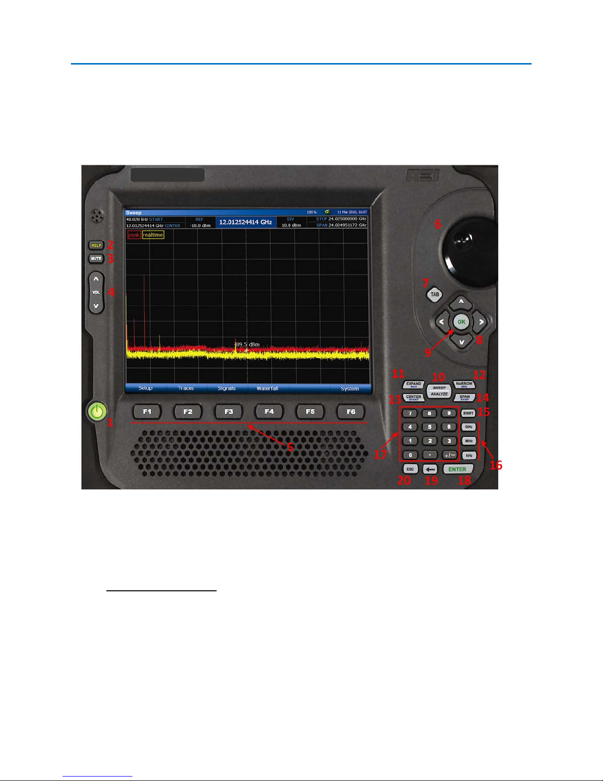
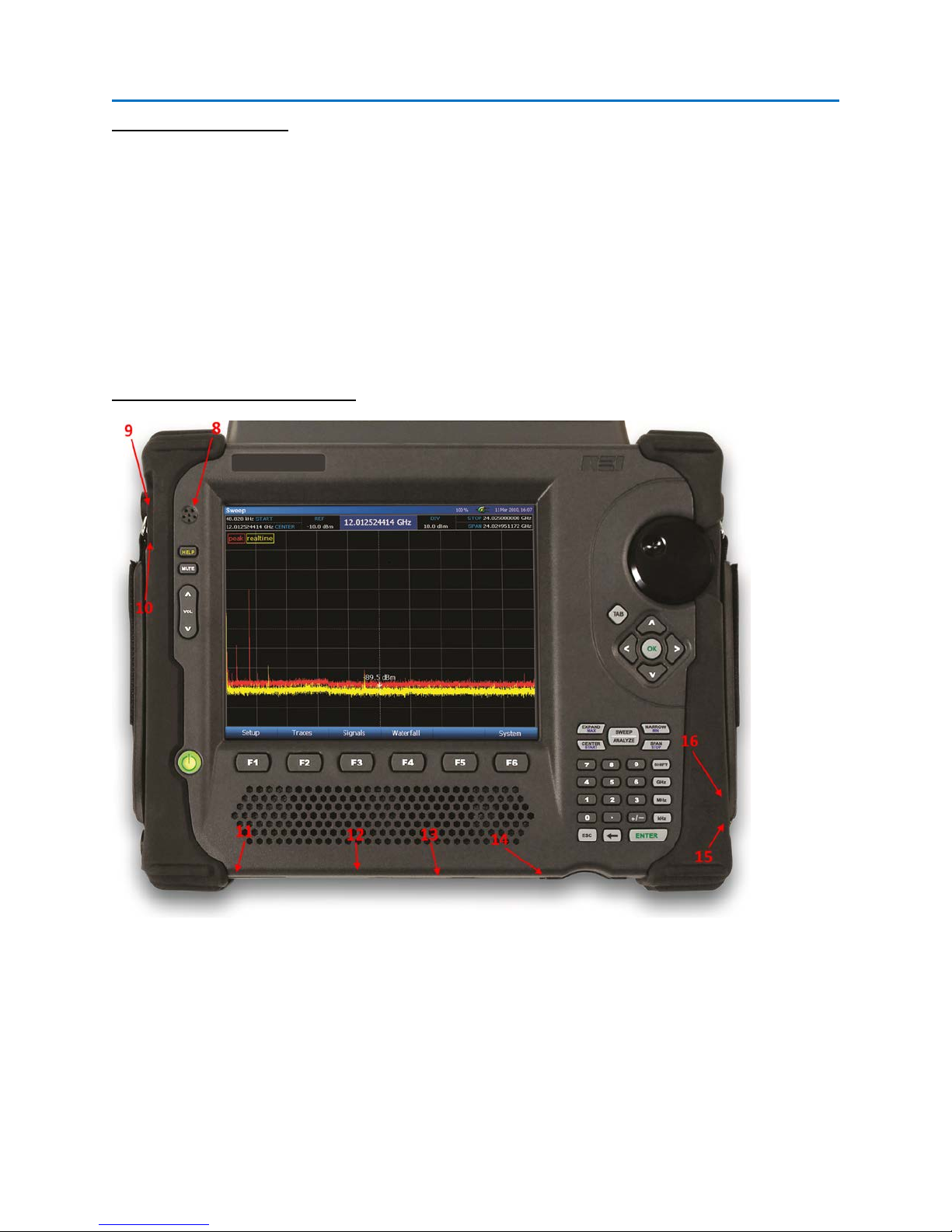
EQUIPMENT DESCRIPTION
Main Panel
1. POWER – turns the unit off and on. Press and hold the power button until the unit shuts off to
do a firmware reset. As the unit powers on, the power button will display various patterns of
solid and blinking colors to indicate successful initialization and self-test. This is a list of the
various colors the power button will display during operation and what each color indicates:
Power Button Indications
With the Unit On:
Solid Blue – Operating on Battery with no AC connected
Solid White – Battery is charging
Solid Green – Battery fully charged
Solid Yellow – No battery detected
Decaying Yellow – Low battery
2
Page 10

SET-UP & BASIC OPERATION
Decaying Red – Low battery, shutdown is imminent
Blinking Red – Battery Fault (disconnect power and remove battery)
With the Unit Off but with AC Power Connected:
Pulsing White – Battery is charging
Blinking Yellow – No battery detected
Blinking Green – Battery is fully charged
2. HELP – launches on-screen help file. Also used as part of the key sequence for capturing screen
shots (see page 21)
3. MUTE – mutes the speakers
4. VOLUME – increases/decreases volume level
5. F-KEYS – multi-use function keys. Functions corresponding to each F-key will be labeled on the
display screen and will change depending on the current mode or sub-menu.
6. ROTARY DIAL – allows precise frequency selection of whichever parameter is currently selected
(START, STOP, CENTER, SPAN, or CURSOR). Also provides ability to adjust various control
parameters.
7. TAB – used to navigate between fields (such as within signal lists or dialog screens)
8. UP/DOWN/LEFT/RIGHT (arrow keys) – function varies depending on context. In sweep mode, if
you are only displaying part of the spectrum, the left and right keys move up and down through
the spectrum.
9. OK – used for confirming selections and displaying context-sensitive menus
10. SWEEP/ANALYZE – allows instant jump between receiver’s spectrum graphic display and
demodulated signal analysis
11. EXPAND/MAX – Expands the displayed frequency span. When the SHIFT key is pressed
immediately before this key, the frequency span is expanded to the max frequency span of
24.025 GHz.
12. NARROW/MIN – Narrows the displayed frequency span. When the SHIFT key is pressed
immediately before this key, the frequency span is changed to the narrowest frequency span of
1.22 MHz.
3
Page 11
SET-UP & BASIC OPERATION
13. CENTER/START – Highlights the CENTER field, to allow changes to the frequency of the CENTER
of the displayed span. When the SHIFT key is pressed immediately before this key, the START
field is highlighted, allowing changes to the displayed START frequency.
14. SPAN/STOP – Highlights the SPAN field, to allow changes to the displayed frequency span.
When the SHIFT key is pressed immediately before this key, the STOP field is highlighted,
allowing changes to the displayed STOP frequency.
15. SHIFT – Used in conjunction with certain buttons to trigger optional operations. Buttons with
included SHIFT operations include smaller blue text with the name of the SHIFT operation.
16. GHz/MHz/kHz – used for inputting frequencies into the START, STOP, CENTER, SPAN, and cursor
fields
17. NUMBER KEYS – used for inputting frequencies into the START, STOP, CENTER, SPAN, and cursor
fields and other data
18. ENTER – used for confirming selections
19. - backspace key
20. ESC – used to exit out of certain input screens
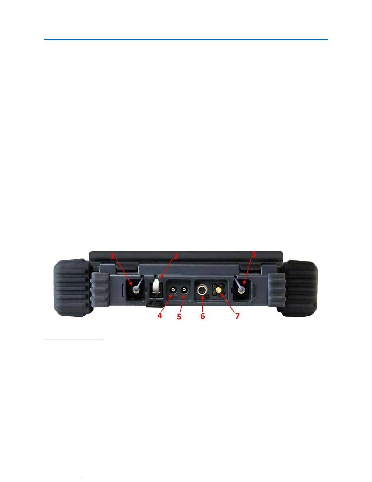
Inputs/Outputs/Accessories
Antenna Panel Inputs
1. 8 GHz – 24 GHz Antenna Input – connection from the antenna panel to the main unit for the 8-
24 GHz antennas
2. Antenna Panel Control – connection from the antenna panel to the main unit for the control
signals used for the automatic antenna switching
3. 0 – 8 GHz Antenna Input – connection from the antenna panel to the main unit for the 50 kHz to
8 GHz antennas
4
Page 12
SET-UP & BASIC OPERATION
Auxiliary Inputs/Outputs
4. Baseband Out – DC-6 MHz baseband output (See page 81)
5. IF Out – 75 MHz IF Out, Center frequency = 75 MHz, 3 dB Bandwidth = 30 MHz. The IF Out port
is active anytime that the unit is in Analyze Mode (see page81).
6. Auxiliary Control Port – digital control for REI supplied accessories, such as the Multi-Purpose
Probe (see page 84)
7. 0 – 8 GHz Aux RF In – Optional RF input for user supplied antennas. Must manually be switched
in the menu (see page 28).
Other Inputs/Outputs/Accessories
8. Microphone – Used for correlation and ranging functions (See page 77).
9. Microphone input – for connection of an external microphone.
10. Headphone output – for connection of headphones to monitor audio from the unit
11. Power input – for AC adapter (only use REI supplied AC Adapter)
5
Page 13
SET-UP & BASIC OPERATION
12. Hard Reset – recessed switch for initiating a hard reset to the unit. This button should only be
used if the unit has locked up or is not functioning normally due to an unforeseen programming
condition.
13. USB-A connector – allows connection of USB flash memory for saving data. A USB keyboard or
mouse may also be connected to the unit to facilitate entry for the various fields.
14. Compact Flash slot – allows connection of compact flash card for saving data.
15. USB-B connector – Not currently utilized. Available for future software functionality.
16. Ethernet connector – Used to access the OSCOR unit remotely using VNC (Virtual Network
Computing) 3
rd
party software.
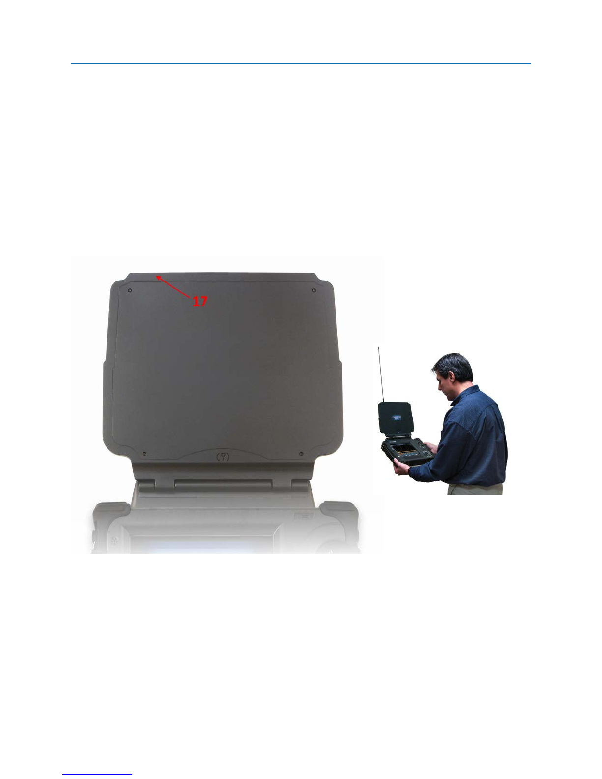
17. Whip Antenna Connector – for connecting the whip antenna accessory to improve low
frequency reception
6
Page 14

SET-UP & BASIC OPERATION
18. Directional Antenna * –Clip the included Vivaldi directional antenna to the antenna panel and
connect to the 0 – 8 GHz Auxiliary input on the back of the OSCOR unit for improved directivity
in the 1.5 GHz to 8 GHz range.
The above picture shows the antenna vertically polarized. Rotate the antenna in the clip to
allow for vertical or horizontal polarization.
* The Directional Antenna is not included in some OSCOR models/versions. If the unit
purchased did not include this antenna, it can be purchased by contacting REI or an Authorized
REI reseller.
19. Multi-purpose Probe (MPP) - The MPP is a small portable probe that
attaches to the auxiliary port of the OSCOR unit and extends its
functionality with the addition of different sensors/antennas to allow the
capture and analysis of suspicious signals: Coaxial Connectors, Carrier
Current Probe (CCP), VLF Antenna (Loop Antenna), Infrared (IR) sensor, and
a Visible Light (VL) sensor. (See page 84.)
7
Page 15
SET-UP & BASIC OPERATION
QUICK START EXERCISES
This section is intended to provide some short exercises to familiarize the user with some of the basic
OSCOR functions and capabilities. These exercises are provided with minimal explanation and assume
that the unit is turned off before starting. Detailed explanations of OSCOR functions and procedures are
provided in later sections of this User’s Manual. Two (2) exercises are provided:
1. Listen to a radio station
2. Basic methods to detect threat transmitters
Exercise 1 – Listen to a Radio Station
This exercise has two parts. The purpose is to gain a quick understanding of how to listen to signals with
2 methods:
a. Entering a known frequency directly.
b. Using the tuner presets and touch screen controls.
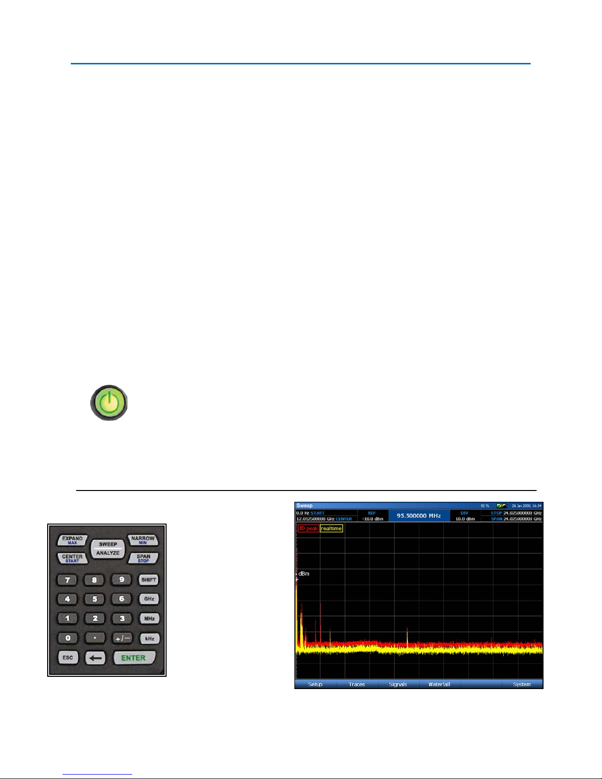
Exercise 1a. – Listen to a radio station by direct frequency entry.
Press the Power button to turn on the
unit.
Type in a known FM
radio station from the
numeric keypad. (95.5
MHz is shown in this
example; You should use
a known station in your
area.)
Type “9”, “5”, “.”, “5”,
MHz
8
Page 16
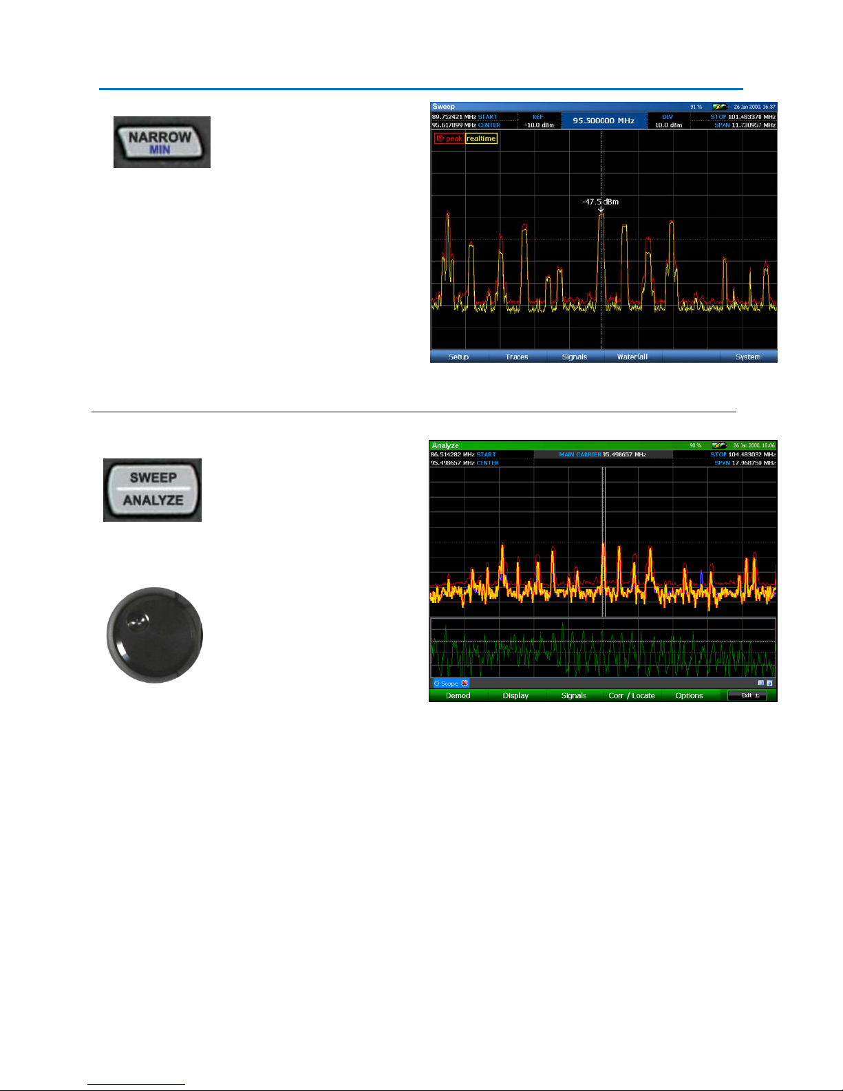
SET-UP & BASIC OPERATION
Repeatedly press the
Narrowbutton to zoom in on
the selected frequency. As
you zoom in, the selected
frequency will center itself on
the screen.
Press SWEEP/ANALYZE to
enter Analyze mode. Press
Mute or Vol Up to listen to
the radio station.
To listen to other known
signals, type in the desired
frequency or use the rotary
knob to move the cursor to
adjacent stations.
9
Page 17
SET-UP & BASIC OPERATION
Exercise 1b. – Listen to a radio station using tuner presets & touch controls.
This exercise assumes that the OSCOR unit is again turned OFF.
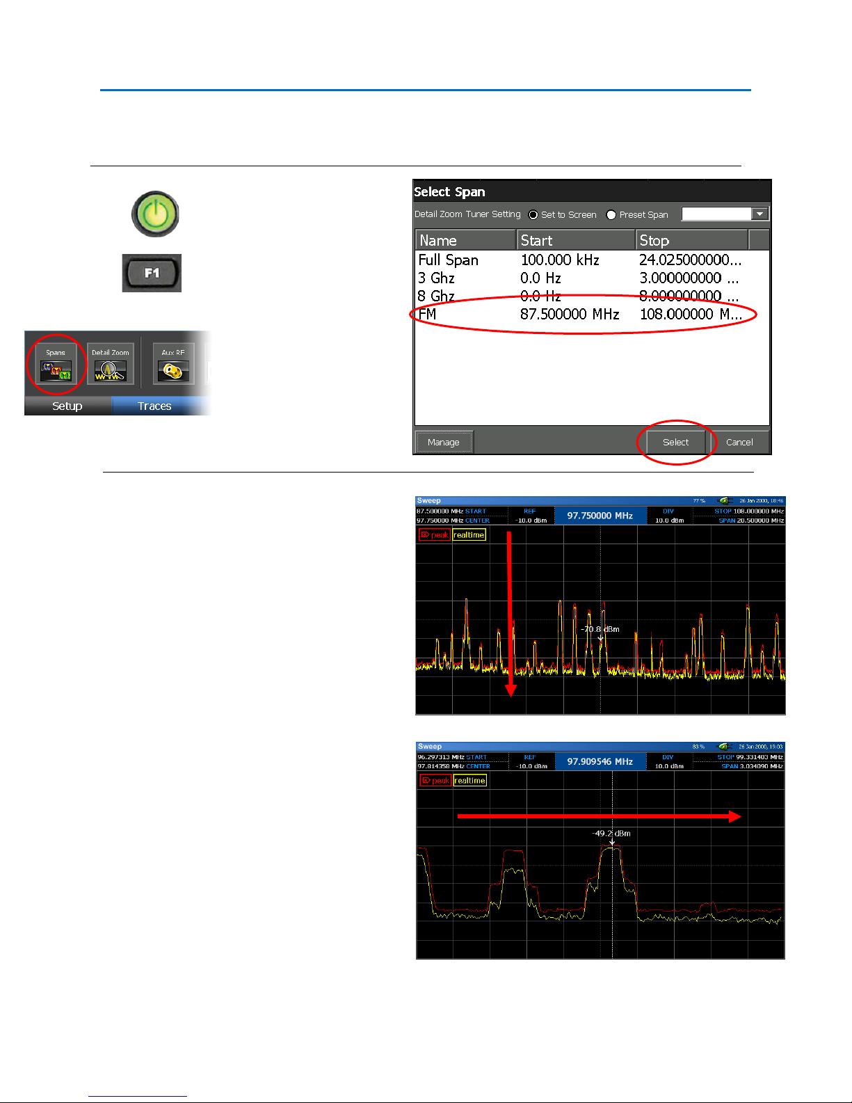
Press the Power button to
turn on the unit.
Press F1 to go to the Setup
Menu. Select the Spans
icon. From the Select Span
dialog box, tap the FM
preset with the stylus and
then press Select. The FM
band will be shown in the
spectral display.
Zoom in on a strong signal in the FM band by
touching the screen within the very top screen
division and dragging with your finger or the
stylus in a downward motion. If you zoom in
too far, simply touch the screen within the very
bottom screen division and drag in an upward
motion.
Pan left or right by touching the left side of the
screen and dragging right or by touching the
right side of the screen and dragging left. You
can also zoom and pan at the same time by
starting within the top screen division and
dragging downward diagonally instead of
straight down.
Position the cursor on the desired signal by
tapping the signal with your finger or the stylus.
10
Page 18
SET-UP & BASIC OPERATION
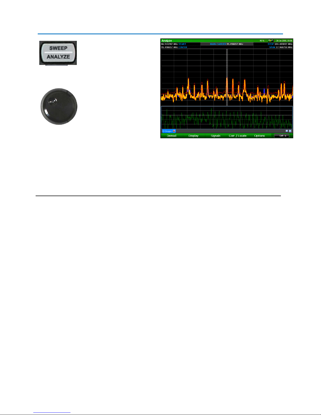
Press SWEEP/ANALYZE to
enter Analyze mode. Press
Mute or Vol Up to listen to
the radio station.
To listen to other known
signals, type in the desired
frequency or use the rotary
knob to move the cursor to
adjacent stations.
When you first enter Analyze Mode, the spectral graph will appear in the top portion of the screen, just
like Sweep Mode. An oscilloscope view of the demodulated signal will appear in the bottom portion of
the screen. Also, by default three traces are displayed in the spectral graph in Analyze Mode: the real
time trace, the peak trace, and an average trace.
Using the techniques of this exercise you should be able to quickly go to any signal for spectrum analysis
and analog demodulation. To practice, it is recommended that you look at several different signals
throughout the frequency spectrum such as pager transmissions, television signals, cellular phone
signals, etc… Options for Video Demodulation can be found within the Demod Sub-Menu, just select the
Video icon. Options for subcarrier demodulation can be found within the Subcarrier Sub-Menu.
11
Page 19
SET-UP & BASIC OPERATION
Exercise 2 – Basic Methods To Detect Threat Transmitters
The purpose of this exercise is to introduce methods for locating threat signals using Peak Traces, Math
Traces, and the RSSI Locate feature.
For this exercise, you will use some type of RF transmitter such as a cell phone, baby monitor, wireless
microphone, or wireless camera. In this documented example a wireless microphone and a wireless
2.4GHz camera were used. This exercise makes the following assumptions:
• There are two rooms being compared, Office A and Office B.
• The transmitters are located in Office A.
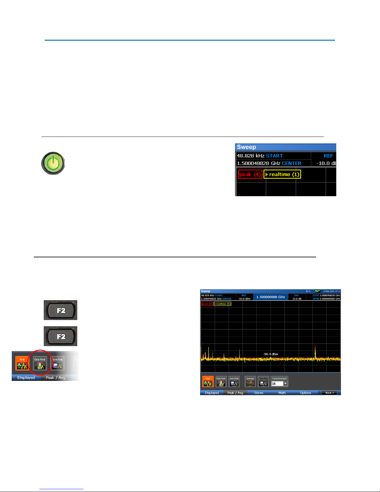
Press the Power button to turn the unit on.
Two traces are displayed when the OSCOR unit is
first started. The real time trace, which is yellow by
default, and the peak trace, which is red by default.
Notice the Sweep Countsdisplayed in the top left corner of the spectral display. This keeps track of how
many sweeps are included in each displayed trace. The sweep count for each trace is displayed beside
the trace name.
We will begin by collecting a peak trace in Office A.
: Each time the OSCOR unit is turned off and on, the peak trace automatically clears itself.
NOTE
However, as a precaution (and for instructional purposes) we will manually clear the peak trace for this
exercise.
Press F2 or select Tracesfrom the Main
Menu to enter the Traces Sub-Menu.
Press F2 or select Peak / Avg to enter
the Peak / Avg Sub-Menu.
Select the Clear Peak iconfrom the Peak
/ Avg Sub-Menu to clear the peak trace.
The peak trace will be cleared and will immediately begin collecting peaks again. Notice the the Sweep
Count Indicator for the Peak Trace resets to 0.
12
Page 20
SET-UP & BASIC OPERATION
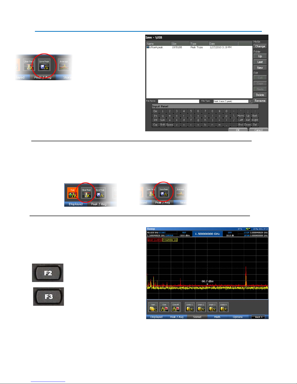
Allow the peak trace to build
for 10-15 sweeps.
Now we want to save this peak
trace in Office A. The Peak /
Avg Sub-Menu should still be
open from the last step. Select
the Save Peak iconfrom the
Peak / Avg Sub-Menu.
In the dialog box that opens,
select a location and a name
for the saved trace. (Ex.
Office A)
At this point walk into Office B to collect a Peak Trace using the same steps as above. It is important to
clear the Peak Trace in Office B to ensure that no signal levels from Office A corrupt the spectrum of
Office B. Save the trace in Office B using the steps given above.
To compare the peak traces, we
need to open both of the peak
traces that were just saved.
From the Main Menu, press F2
or select Traces from the Menu.
From the Traces Sub-Menu,
press F3 or select Stored with
the stylus.
13
Page 21
SET-UP & BASIC OPERATION
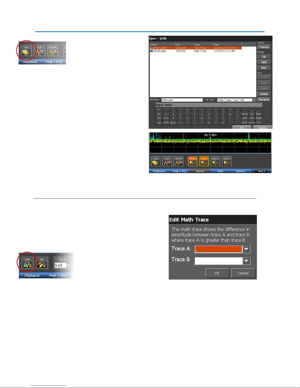
From the Stored Sub-Menu,
select the Open icon. In the
dialog box that appears, find and
select one of the traces that you
saved. Press OK.
This trace will now be displayed
on the screen. Notice that the
Empty 1 icon in the Stored SubMenu now contains the name of
this saved trace and the color of
the outline around the icon will
match the color of the trace in
the spectral display. Repeat the
process for both traces
Note: Up to four saved traces can be opened on the OSCOR unit at any given time. After four traces have
been opened, a trace must be closed before any additional traces can be opened.
Now we want to create a Math Trace
from the two peak traces we just
opened. While still in the Traces SubMenu, press F4 or select Math from the
Traces Sub-Menu.
From the Math Sub-Menu, select the
Mathicon.In the Edit Math Trace dialog
that opens, select the 1
(Office A) for Trace A and the 2
st
saved trace
nd
saved
trace (Office B) for Trace B. Press OK.
Even without your test transmitter, there will be some differences in the traces due to intermittent
transmitters in the environment, such as other cell phones, Wi-Fi, etc… The strongest signal that shows
up on the difference plot should be your test transmitter. It will be necessary to use the methods from
the previous exercise for zooming and navigating the spectral display to locate the test transmitter.
14
Page 22
SET-UP & BASIC OPERATION
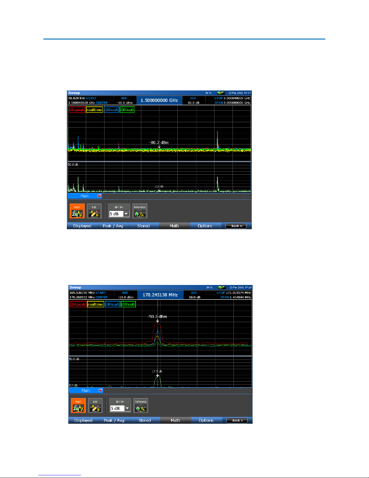
The Math Trace, which should now be displayed, shows a graphical difference of the peak trace
generated in Office B compared to Office A. In the screen shot below, the spectrum was zoomed down
to a 3GHz window to see the areas of the spectrum that contain the greatest differences. In this
example, there are clearly some differences and each area of the spectrum should be closely examined.
Zooming into one of these areas, it is easy to identify that a strong transmitter exists in Office A at
170.2MHz.
15
Page 23

SET-UP & BASIC OPERATION
RSSI Level increases as
We will now locate this transmitter in Office B using the RSSI Locate function.
Press Sweep/Analyze to enter Analyze
Mode. In this example, the wireless
microphone was demodulated and
“listened” to using the audio demod.
To Locate the transmitter select Corr /
Locate or press F4.
Select the RSSI Level icon. The oscilloscope
view will be replaced with an RSSI graph.
(Note: RSSI stands for Relative Signal
Strength Indicator.)
Adjust the threshold to be able to see subtle variations in the RSSI level better. Select the Threshold
icon. Using the Rotary Knob, adjust the threshold level slightly below the signal level for your
transmitter. When finished press the OK button.
Begin walking around the room carrying the OSCOR
unit. Observe the RSSI graph on the bottom portion
of the display. As you get closer to the transmitter,
the level of this graph will increase indicating the
close proximity of the transmitter. As you walk
further away from it, the RSSI level will decrease. You
may need to use the Thresholdicon and the rotary
knob to adjust the RSSI level graph; be sure to press
the OK button or the ENTER button to set the
threshold.
Locating the Wireless Camera
Using a similiar procedure, the Wireless Camera is
identified, demodulated, and located.
In this example, there was a Wireless LAN transmitter
in Office A that occupied the same frequency as the
camera. However, careful evaluation of this band and
the video revealed the camera within the 2.4GHz
band.
the OSCOR unit gets
closer to the
transmitter.
16
Page 24
SET-UP & BASIC OPERATION
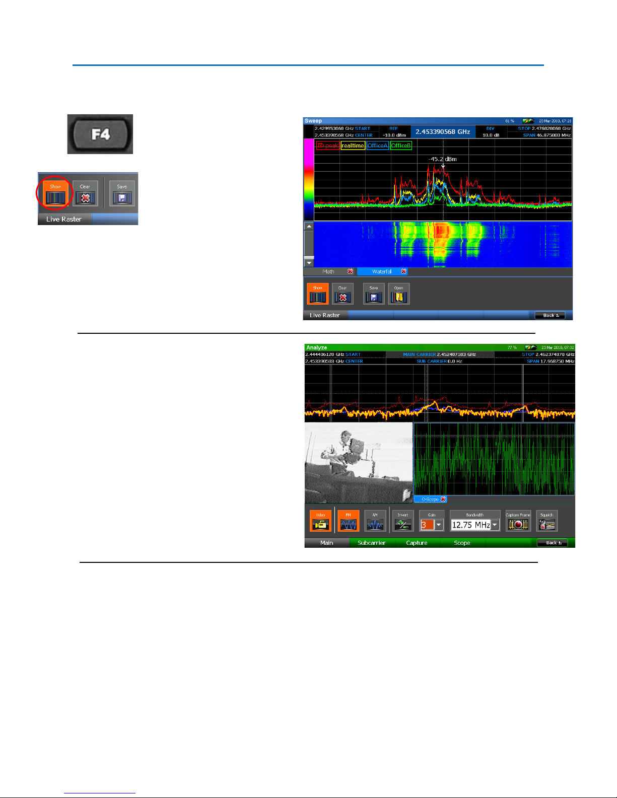
You can use the previous location method of monitoring the signal RSSI level as you walk around the
room, but for this example we will use the Live Waterfall Raster to locate the wireless camera.
Press F4 or select Waterfall from
the main menu. Then select the
Showicon.
Walk around the room moving
the OSCOR unit close to various
surfaces in the room until the
signal level becomes very strong.
At this point, it is easy to see the shape of the
wireless camera transmission in comparison to
the normal Wi-Fi traffic. This procedure should
also work for many more types of transmitters.
To view the video transmitter, press the
Sweep/Analyze button, then select the Video
icon from the Demod Sub-Menu. You may need
to adjust the tuning or the demodulation
parameters.
These Quick start exercises do not cover all of the functionality of the OSCOR unit.
However, these exercises are given to provide some quick examples of how to use the product and to
familiarize the user with many of the main functions and concepts.
It is recommended to use the entire manual for more detailed explanations of the OSCOR unit functions.
17
Page 25
SET-UP & BASIC OPERATION
SET-UP & BASIC OPERATION
The OSCOR is a stand-alone spectrum analyzer with a built-in antenna panel ready to be used right out
of the box. Depending on your application, some adjustments to the default settings may need to be
made.
Power Control and Battery Charging
To turn on your OSCOR unit, ensure that a charged battery is in the unit or connect the supplied AC
adapter and press the power button (see page 2). During operation, to turn off your OSCOR unit, press
and release the power button or select the Shutdown icon from the System Sub-Menu.
Press and hold the power button until the unit shuts off to perform a firmware reset. This method
should only be used if the unit has locked up and the normal shutdown methods are not functioning.
The OSCOR unit has a built in battery charger. To charge the battery, simply plug the supplied AC
adaptor into the unit with the battery in the OSCOR unit. Expected charge time is 1.5 hours; expected
run time is 3 hours.
Note: It is recommended that the OSCOR battery be recharged on a regular basis during extended
periods of storage (3 months or more) to prevent damage to the battery. Additionally, when storing the
OSCOR for long periods (1 month or more), it is recommended that the battery be removed from the
unit and placed in the storage compartment in the case. Storing the OSCOR with the battery in the unit
can deplete it more rapidly, potentially shortening the life of the battery.
Updating the Software and Firmware
Software updates, provided in the form of an .O2update file, will be made available by contacting REI
at sales@reiusa.net
1. Place the downloaded .O2update file on a USB thumb drive or Compact Flash card and connect
the media to the OSCOR unit.
. To update your OSCOR unit:
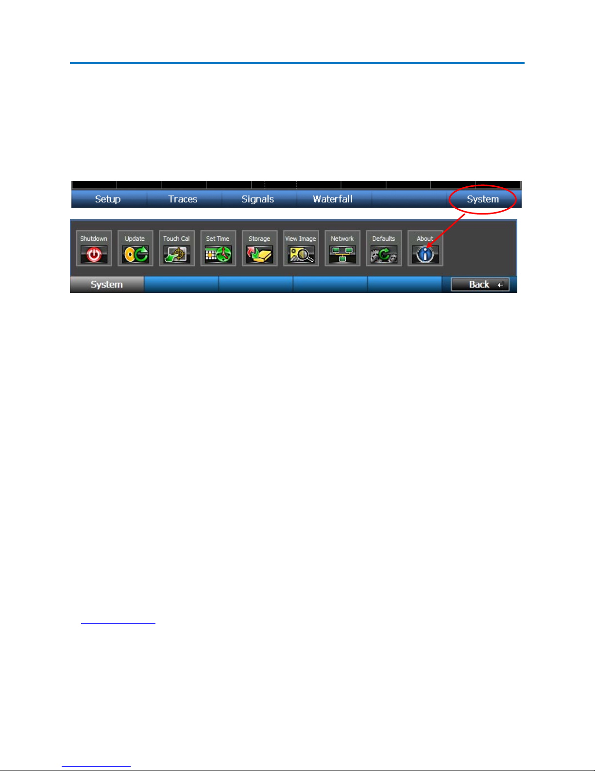
2. From the Main Menu, select System or press F6.
18
Page 26

SET-UP & BASIC OPERATION
3. From the System Sub-Menu, select the Update icon. In the dialog box that opens, select the
media containing the update file (\USB or \CF), highlight the .O2update file, and press the OK
button.
4. The system will ask for confirmation to run the update. Select Yes or press F5 to run the update.
Select No or press F6 to cancel the update.
5. The OSCOR will now update the software. Note: Depending on the extensiveness of the update,
the process could take several minutes and may shut down and restart the unit several times.
6. After a successful update, remove the thumb drive or compact flash card and save the
.O2update file as a back-up.
Notes
- Contact REI at sales@reiusa.net
- .o2update files also contain updates to the firmware for the MPP. When an MPP is connected
to the OSCOR unit (see page 84) if the software on the unit is incompatible with the software on
the MPP, the unit will automatically update the firmware on the MPP. A dialog box will appear
when the MPP is connected informing you that an MPP firmware update is required. Press OK
to begin the update and then follow any subsequent screen prompts.
for software update notification.
Help File
To access the on-screen help file, press the HELP key. The contents of the help file will vary depending
on the mode the OSCOR is in when the help file is launched.
Within the help file there are several methods of navigating through the information:
- Click on hyperlinks with the stylus to jump to the referenced location in the help file.
- Click Back or press F1 after clicking on a hyperlink to return to the previous file location.
- After clicking Back to return to previous file locations, the Forward button or F2 will
jump forward through your list of previous file locations.
- Press the UP ARROW key and the DOWN ARROW key to scroll the text up or down.
- Click and drag the scroll bar on the right side of the screen to scroll the text up or down.
- Press SHIFT + UP ARROW or SHIFT + DOWN ARROW to page up or page down within
the help file.
To close the on-screen help file, select Close or press F6.
19
Page 27
SET-UP & BASIC OPERATION
Setting the Time Zone, Date, and Time
Setting up the time zone, date, and time will give you accurate timestamps on any recorded data. To set
up this information on the OSCOR unit:
1. From the Main Menu, select System or press F6
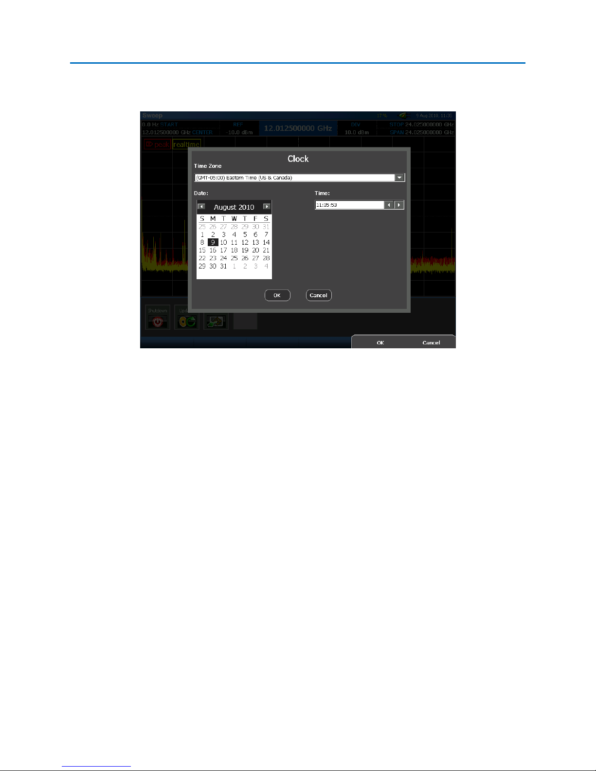
2. From the System Sub-Menu, select the Set Time icon.
3. In the dialog box that opens, select the corresponding time zone for your area from the Time
Zone drop down box.
4. To quickly adjust the current date, tap the month on the displayed calendar with the stylus and
select the current month from the drop down list that appears. Tap the year with the stylus and
enter the current year using the numeric keypad or adjust using the scroll arrows next to this
item. After setting the month and year, select the current day from the displayed calendar.
5. To quickly set the current time, each portion of the displayed time (hour, minute, seconds) can
be selected individually and entered using the numeric keypad or adjusted using the scroll
arrows next to the time display.
6. Select the OK button or press F5.
20
Page 28

SET-UP & BASIC OPERATION
Touch Screen Calibration
The easiest method to access and control OSCOR functions is to use the built in Touch Screen. There is a
stylus located in the grip which will give the most precise control on the touch screen. In order to
properly align the touch screen to the display, it may be necessary to calibrate the touch screen.
To calibrate the touch screen:
1. From the Main Menu select System or press F6.
2. Select the Touch Cal icon from the System Sub-Menu.
3. Follow the on-screen instructions.
Note: Calibration should only be required after a complete software update is performed.
Saving Screen Shots to Thumb Drive
To assist in report-writing, the OSCOR provides the ability to capture screen shots from the display.
Screen shots can be stored as PNG or BMP (bitmap) files and can be saved to a Compact Flash card or to
a USB thumb drive. To use this function, insert a Compact Flash card into the compact flash slot or
insert a thumb drive into the USB port on the front of the OSCOR unit. Then press the following key
sequence to store the current screen image:
• SHIFT
• HELP
If successful, a Save Dialog box will open. The currently selected media, either compact flash (\CF) or
thumb drive (\USB) will be displayed at the top of the dialog box. To change where you want to store
the image file, press Change in the Media section on the right hand side of the dialog box and then
select either \CF or \USB. After naming the file and selecting a file type, press OK to save the image file.
File Operations
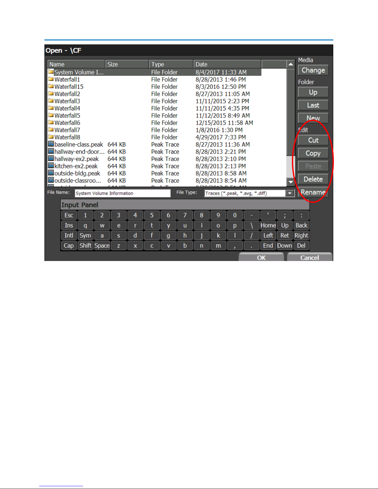
The file dialogs on the OSCOR, such as the file open and file save dialogs, contain Cut, Copy, Paste,
Delete, and Rename operations which allow the user to copy or move files from a compact flash card to
a USB flash drive, as well as other file operations, on the OSCOR unit without having to do this on a PC.
To access these functions, open a file dialog box. For example, you could press SHIFT + HELP to open the
Screen Shot File Dialog described above or you could use the Open File Dialog (see page 36). Highlight
the file that you wish to perform file operations on by clicking on it and then press the button
corresponding to the file operation you wish to perform.
21
Page 29
SET-UP & BASIC OPERATION
Using the Storage Manager
USB Hard Drives must be formatted with a FAT file system, such as FAT32, for use with the OSCOR unit.
Hard drives formatted with the NTFS file system will not be recognized by the OSCOR. Windows
operating systems limit the storage capacity of a FAT32 partition to less than 32 GB when formatting.
Third party software does exist which will allow you to format a larger partition using FAT32. To assist
with setting up large capacity drives, the OSCOR unit features a storage manager that will partition and
format any size hard drive using FAT32.
To format a USB hard drive using the Storage Manager:
1. Connect the USB hard drive to the USB-A connector on the front of the OSCOR unit.
2. From the Main Menu select System or press F6. Select the Storage icon from the System Sub-
Menu.
22
Page 30
SET-UP & BASIC OPERATION
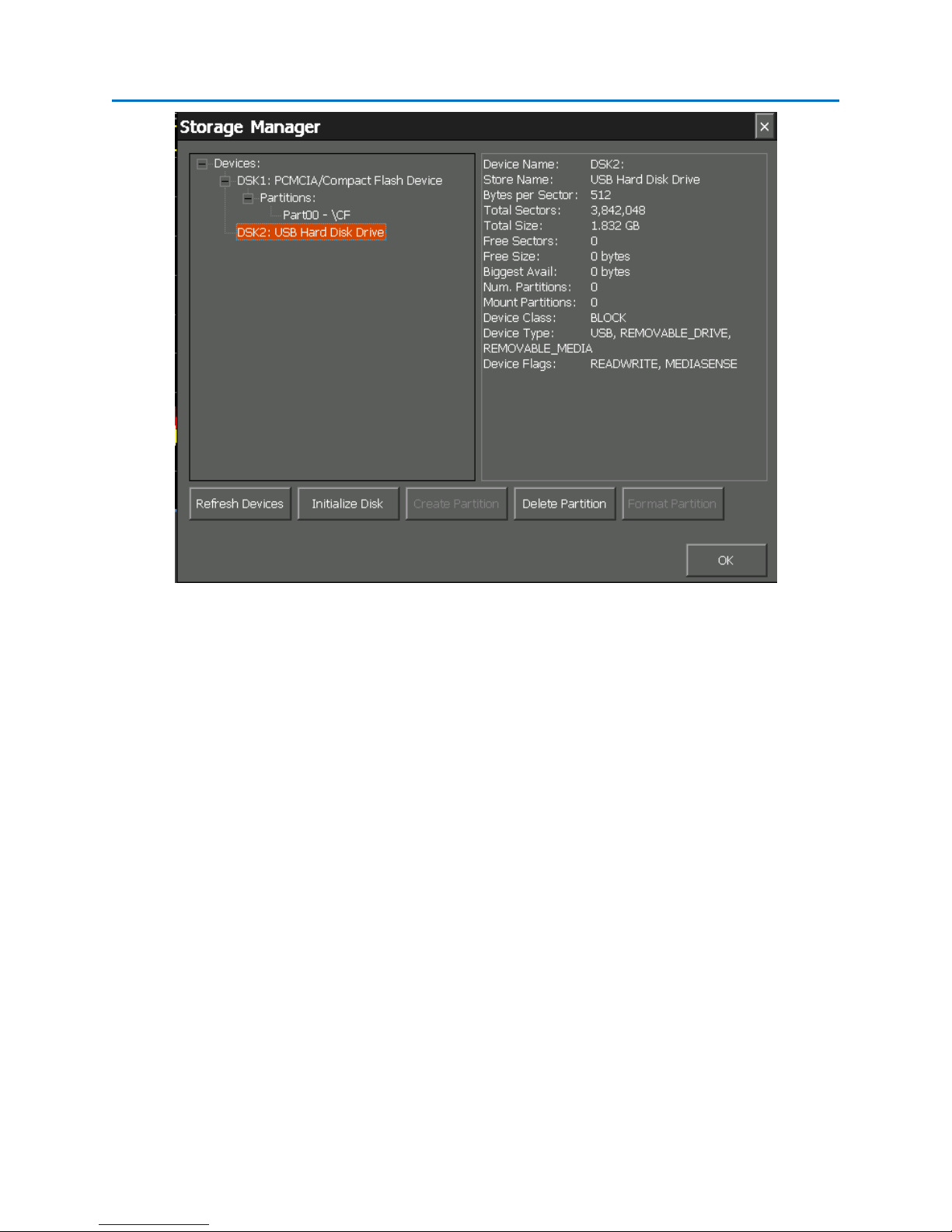
3. The storage manager will open. Connected storage devices will be shown in the tree list on the
left side of the storage manager window.
4. Find and Select the device you wish to format from the tree list in the storage manager.
Properties for the device will be displayed on the right side of the storage manager window.
Any existing partitions will be listed below the device name in the tree list. If Free Size (listed in
the property pane on the right side of the storage manager) is equal to 0 bytes and there are no
existing partitions for the device, you will need to initialize the disk. Press Initialize Disk. If Free
Size is not equal to zero or the Initialize Disk button is grayed out skip to the next step. If a
partition already exists on the device, skip to step 6.
5. Make sure that the device that you want to format is still selected. Press Create Partition. In
the dialog box that appears, type a name for the partition and select OK. The storage manager
will only create one partition per device. The partition size will automatically be the maximum
size possible for the given storage device.
6. Select the partition that you wish to format. If the partitions are not shown in the tree list,
select the “+” sign next to “Partitions:” under your device in the list. Select Format Partition. In
the dialog box that opens, confirm that you would like to format the partition by selecting Yes.
WARNING Any existing data on the storage device will be lost! Make sure to transfer any data
you wish to keep to another device before performing the Format Partition function.
23
Page 31

SET-UP & BASIC OPERATION
Several other tasks can be performed from the Storage Manager:
• Refresh Devices – When the storage manager is first open, it will automatically detect all storage
devices connected to the OSCOR. However, while the storage manager is open, if devices are
connected or disconnected, it may be necessary to press Refresh Devices to refresh the tree list.
• Delete Partition – Select a partition in the tree list and press Delete Partition to delete the
partition. WARNING Any existing data on the partition will be lost! Make sure to transfer any
data you wish to keep to another device before performing the Delete Partition function.
Resetting to Factory Defaults
If you have changed any of the settings on your OSCOR unit, such as trace colors or preset spans, it is
possible to reset the unit to the default conditions shipped from the factory.
To reset to factory defaults:
1. From the Main Menu, select System or press F6.
2. From the Systems Sub-Menu, select the Defaults icon.
3. The system will ask for confirmation to restore system settings to their defaults. Select Yes or
press F5 to restore the default settings. Select No or press F6 to cancel.
The following stored system settings will be restored to their default settings:
- Trace Colors
- Custom Spans
- Color Gradient Settings
- Visibility state of graph adornments, such as the Trace Legend and Sweep Counts
Note: If you have created several custom spans that you wish to save, you may want to export these
custom spans (see page 26) before resetting to factory defaults, so that you can easily restore them
afterwards.
Setting up the Tuner
24
Page 32
SET-UP & BASIC OPERATION
Preset Spans
The range of frequencies swept by the tuner, or tuner span, can be adjusted during operation by
changing one or more of the spectral parameters (see page 32). Custom spans may be configured,
named, and stored in memory for easy recall later. Several default tuner spans are available on the
OSCOR from the factory:
o Full: The tuner will sweep the entire frequency range available on the OSCOR (100 kHz
to 24 GHz for 24 GHz models and 100 kHz to 8 GHz for 8 GHz models)
o 3 GHz: The tuner will sweep from 100 kHz to 3 GHz
o 8 GHz: The tuner will sweep from 100 kHz to 8 GHz (available on 24 GHz models)
o FM: The tuner will sweep the FM radio broadcast band, from just below 87.5 MHz to
108 MHz
To change the tuner span:
1. From the Main Menu select Setup or press F1.
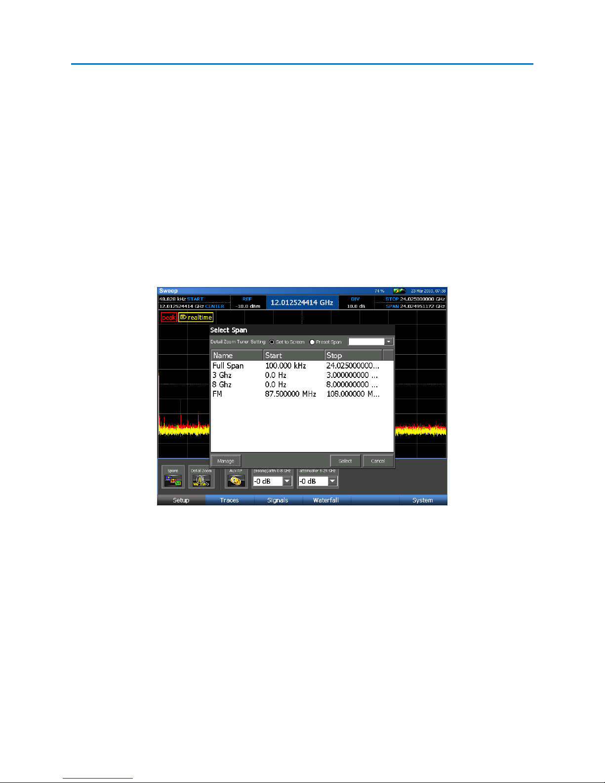
2. Select the Spans icon from the Setup Sub-Menu.
3. In the Select Span dialog box that appears, a list of available user spans will be displayed.
4. Highlight the desired user span and press Select. The dialog box will close and the new span will
be applied.
Note: If Detail Zoom is on (see page 45), the selected span will apply to the Detail View and not to the
tuner. If the selected span is outside the range of the current tuner span, then the new span will not be
applied to the Detail View.
25
Page 33

SET-UP & BASIC OPERATION
Managing Preset Spans
Custom spans can be created and stored for later recall. After creating a custom span, it will be
displayed in the list of available tuner spans.
1. From the Main Menu select Setup or press F1.
2. Select the Spans icon from the Setup Sub-Menu.
3. In the Select Span dialog box that appears, select Manage.
4. In the Manage User Spans dialog box that appears, select New.
5. In the Edit Span form that opens, enter a name for the custom span, a start frequency, and a
stop frequency. Press OK.
6. The new custom tuner span will now be available in the list of tuner spans.
Several other user span maintenance tasks can also be performed from the Manage User Spans dialog
box:
• Edit: Allows you to edit the configuration for the highlighted custom span.
• Delete: Deletes the highlighted custom span.
• Import: Imports user spans from a previously exported user spans file.
• Export: Exports current user spans, including any custom spans, to a comma separated values
file (.csv).
• Defaults: If any of the factory default tuner spans get deleted, this function restores them so
that they are once again displayed in the list of available tuner spans. Defaults will also remove
any custom spans that have been created. If you have custom spans that you wish to save,
export them before using the defaults function, so that you can easily restore them afterwards.
Setting up the Display
Several items on the display can be customized depending on the information that needs to be seen on
the screen:
Showing/Hiding the Trace Legend
A legend is available to help identify traces on the screen. The legend is turned on by default and is
located in the upper left corner of the spectral graph (see page 31).
26
Page 34
SET-UP & BASIC OPERATION
1. From the Main Menu, select Traces or press F2.
2. From the Traces Sub-Menu, select Options or press F5.
3. To show or hide the legend, press or toggle the Legend icon.
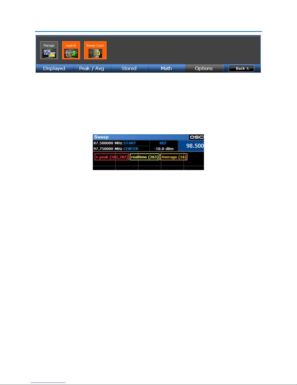
Showing/Hiding the Sweep Counts
It is possible to have the trace legend display the number of sweeps included in the real time trace, peak
trace, average trace(if displayed), and any open stored traces. Most of the time, especially when the
tuner is sweeping the full 24 GHz span, the sweep count for the real time trace will just be 1. However,
when the tuner span is set to a small range, the tuner will sweep the given spectrum many times before
the display is updated. In these cases the sweep count for the real time trace could be as high as 100 or
more and the real time trace will actually be a peak trace of the sweeps that have occurred since the last
screen update. A sweep count of 582,282 for a peak trace indicates that there are 582,282 sweeps of
the spectrum included in that peak trace. A peak trace will continue building and its sweep count will
continue increasing until the peak trace is cleared (see page 35). The Average Trace sweep count will
indicate the number of sweeps included in the displayed Average Trace. Sweep counts are turned on by
default. To show or hide the sweep counts in the trace legend:
1. From the Main Menu, select Traces or press F2.
2. From the Traces Sub-Menu, select Option or press F5.
3. To show or hide sweep counts, press or toggle the Sweep Count icon.
Adjusting the Input Attenuation
Since the OSCOR is a highly sensitive receiver, it is possible for very strong signals to have an overloading
effect on the receiver circuitry. Receiver overload (see page 63) is evidenced by strong signals appearing
at harmonic frequencies and/or from intermodulation distortion. The built-in attenuator should be
27
Page 35

SET-UP & BASIC OPERATION
turned on to reduce or eliminate the RF overload. Two separate attenuators exist for the 24 GHz
models: one attenuator for the 0-8 GHz range and a separate attenuator for the 8-24 GHz range. Each
attenuator offers three different levels of RF attenuation.
1. From the Main Menu, select Setup or press F1.
2. There are two different drop-down boxes in the Setup sub-menu for the two separate
attenuators (24 GHz models only). The drop-down box labeled “preamp/attn 0-8 GHz” sets the
attenuation level for the 0-8 GHz range and the drop-down box labeled “attenuator 8-24 GHz”
sets the attenuation level for the 8-24 GHz range. Select or touch the current attenuation level
for the desired range with the stylus. A list of the available levels will pop up.
3. To turn on the RF attenuator, select one of the three available attenuation levels: -10 dB, -20 dB,
-30 dB (Note: the “+10 dB” value on the 0-8 GHz range activates the built-in pre-amp, see “Using
the Built-in Pre-Amp” below.)
4. To turn off the RF attenuator, select 0 dB
Using the Built-in Pre-Amp
In certain situations when dealing with low level signals which are partially obscured by the noise floor,
it may be necessary to boost the signal strength. This can be accomplished by using the built-in pre-amp
provided on the OSCOR unit. The built-in pre-amp only affects frequencies in the 0-8 GHz range. To
turn on the pre-amp:
1. From the Main Menu, select Setup or press F1.
2. In the drop-down box labeled “preamp/attn 0-8 GHz” change the value to “+10 dB”.
Using an External Antenna
There may be situations where you wish to use another antenna with the OSCOR unit, such as the
included Directional Antenna (see page 7). An Auxiliary RF input from 0-8 GHz is provided on the unit
for this purpose.
1. Connect an external antenna to the Auxiliary RF input (see page 5) on the back of the OSCOR
unit. The Auxiliary RF connector is an SMA female connector. If your antenna uses a different
type of connector it may be necessary to use an adaptor to connect the antenna to the OSCOR
unit.
2. From the Main Menu, select Setup or press F1.
28
Page 36

SET-UP & BASIC OPERATION
3. Select the Aux RF icon from the Setup Sub-Menu. When the background of the Aux RF icon is
orange, the 0-8 GHz Auxiliary RF input is active. When the background of the Aux RF icon is
gray, the 0-8 GHz Antenna input is active.
4. The tuner will now switch to your connected antenna.
29
Page 37

OPERATION
SWEEP MODE
Sweeping the RF Spectrum
When you first power up your OSCOR unit, it will by default enter Sweep Mode. This section describes
the controls for navigating the spectrum and the tools necessary for doing trace analysis in Sweep
Mode.
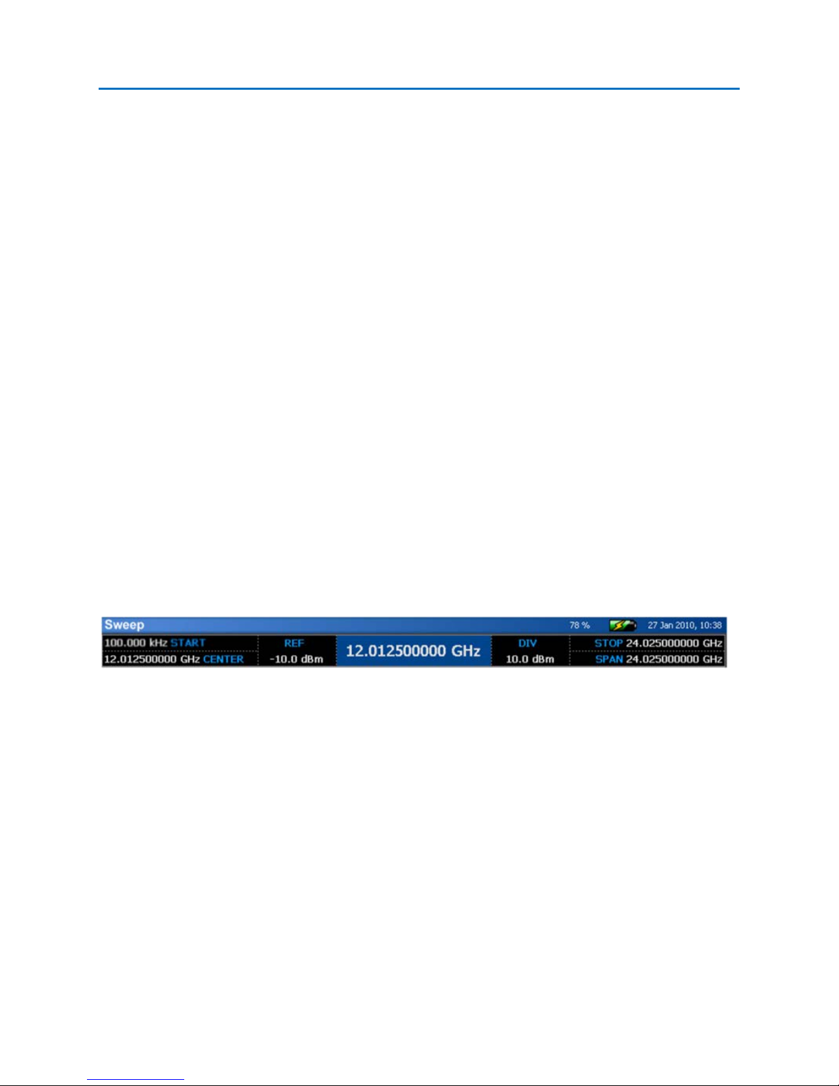
Sweep Mode Screen Elements
1. Mode Indicator – indicates current mode
2. Spectral Parameters (Start, Stop, Center, Span) – these parameters display information
pertaining to the frequency range that is being scanned by the OSCOR’s tuner.
3. Reference Level – indicates current reference level. The reference level can be adjusted by
selecting the reference level indicator with the stylus and either entering a new reference level
with the numeric keypad or scrolling through possible values using the rotary dial. To reset the
30
Page 38

OPERATION
reference level to the default, press the OK button and select Default Range from the context
menu that pops up. This will also reset the dBm/div value to default.
4. dBm/div indicator – indicates the number of dBm per screen division. The dBm/div value can
be adjusted by tapping twice on the dBm/div indicator with the stylus and selecting a new value
from the drop down list. To reset the dBm/div value to the default, press the OK button and
select Default Range from the context menu that pops up. This will also reset the reference
level to default.
5. Cursor Value – indicates the cursor frequency position
6. Cursor – dotted vertical line. A small arrow indicates the power level at the current cursor
position. The value is displayed just above the arrow.
7. Legend – indicates which traces are currently displayed on the screen and identifies the color of
each trace. Sweep counts are not shown in this screenshot, but can be displayed in the legend
(see page 27).
8. Menu Options – Menu options are displayed along the bottom edge of the screen.
Navigating the Spectral Display
The OSCOR unit is capable of scanning and displaying a large portion of the RF spectrum. In order to
fully analyze the RF energy in a given location, it may be necessary to focus on smaller portions of the RF
spectrum at a time. This can be accomplished by using one of several available methods:
- Center on Cursor: If your spectral display is not currently set to maximum span and your cursor
is not at the center of the spectrum, press the OK button and select Center on Cursor from the
context menu that pops up. The OSCOR display will move the frequency of the current cursor
position to the center of the display. The OSCOR will not change the span of the display, so if
the span is near the maximum and the cursor is too far off center, then the OSCOR will only
position the cursor frequency as close to center as possible without changing the span. Note: If
no context menu appears when OK is pressed, tap the spectral display with the stylus or your
finger and then press OK again.
- Click & Drag - Pan: If your spectral display is not currently set to maximum span, clicking on the
right side of the spectral display with the stylus or your finger and dragging to the left will pan
the spectral display to higher frequencies. Clicking on the left side of the spectral display with
the stylus or your finger and dragging to the right will pan the spectral display to lower
frequencies. Your SPAN parameter will remain constant, but your START, STOP, and CENTER
parameters along with the CURSOR position will change as the spectral display pans.
- Arrow Keys – Pan: If your spectral display is not currently set to maximum span, pressing the
RIGHT ARROW key will jump up one half screen to the next set of higher frequencies. Pressing
31
Page 39
OPERATION
the LEFT ARROW key will jump the currently displayed span down one half screen to the next
set of lower frequencies. Your SPAN parameter will remain constant, but your START, STOP, and
CENTER parameters along with the CURSOR position will change as the spectral display pans.
- Click & Drag – Narrow: Clicking within the very top screen division and dragging with your finger
or the stylus in a downward motion will decrease or narrow the size of the displayed span. You
may also pan at the same time that you are narrowing the span by dragging downward
diagonally as opposed to straight down.
- Click & Drag – Expand: Clicking within the very bottom screen division and dragging with your
finger or the stylus in an upward motion will increase or expand the size of the displayed span.
You may also pan at the same time that you are expanding the span by dragging upward
diagonally as opposed to straight up.
- Narrow key: Pressing the NARROW key will decrease or narrow the size of the displayed span by
one half of the current value until the minimum span is reached.
- Expand key: Pressing the EXPAND key will increase or expand the size of the displayed span by a
factor of two until the maximum span is reached.
- Max key: Pressing SHIFT + EXPAND (MAX) will increase or expand the size of the displayed span
to the maximum frequency span.
- Min key: Pressing SHIFT + NARROW (MIN) will decrease the size of the displayed span to the
minimum frequency span.
Changing the Spectral Parameters
There are several ways to change the spectral parameters:
- With the stylus, double click any of the spectral parameters (Start, Stop, Center, Span). A virtual
keypad will appear on the screen. Using the virtual keypad, enter the desired value for the
selected spectral parameter, then press one of the unit keys (kHz, MHz, GHz) to initiate the
change. Press ESC to discard any changes.
- Select the desired spectral parameter with the stylus so that it is highlighted. Using the number
keypad on the OSCOR unit, enter the desired value, then press one of the unit keys (kHz, MHz,
GHz) to initiate the change.
- Select the desired spectral parameter with the stylus so that it is highlighted. Turn the rotary
knob to change the value of the selected spectral parameter.
32
Page 40

OPERATION
- Press the CENTER, SPAN, SHIFT + CENTER, or SHIFT + SPAN button to highlight the CENTER,
SPAN, START, or STOP parameters respectively. Enter a value using the number keypad,
followed by a unit key (kHz, MHz, GHz) to initiate the change or turn the rotary knob to change
the selected parameter’s value.
Note: The minimum START frequency in sweep mode is 100 kHz. If you are using an auxiliary
antenna and want to evaluate signals down to 50 kHz, use Analyze Mode (see page65).
Changing the Position of the Cursor
There are several ways to change the position of the cursor:
- To move the cursor to the center of the screen: Press the OK button. Select Cursor to Center
from the context menu that pops up. Note: If no context menu appears when OK is pressed, tap
the spectral display with the stylus or your finger and then press OK again.
- With the stylus, double tap the cursor value at the top center of the screen. A virtual keypad
will appear on the screen. Using the virtual keypad, enter the desired value for the cursor, then
press one of the unit keys (kHz, MHz, GHz) to initiate the change. Press ESC, if you do not wish
to change the cursor position.
- Select the cursor value at the top center of the screen with the stylus so that it is highlighted.
Using the number keypad on the OSCOR unit, enter the desired value, then press one of the unit
keys (kHz, MHz, GHz) to initiate the change.
- Select the cursor value at the top center of the screen with the stylus so that it is highlighted.
Turn the rotary knob to change the cursor position.
Note: Setting the cursor to a value that is not within the currently displayed span will reset the START &
STOP frequencies of the current span, so that the cursor at the new value will be centered on the screen
within a span of the current bandwidth.
RF Spectrum Trace Display Modes
The OSCOR provides several different ways to view the RF spectrum in sweep mode. These methods are
very useful to detect and find sophisticated threats such as Spread Spectrum, Frequency Hopping, and
Burst transmitters. These trace modes are defined below:
• Real Time Trace – Provides the most recent view of the RF spectrum. This data is not stored.
• Peak Trace – this trace is updated based on the maximum values measured from the real
time trace data. The peak trace is constantly being updated until it is cleared and then the
peak trace memory buffer is reset. Peak traces can be saved for later analysis.
33
Page 41

OPERATION
• Average Trace –Trace display mode developed by averaging the real time trace data.
Average traces can also be saved for later analysis.
• Math Trace – Displays differences in amplitude between any two open traces. Useful for
comparing traces taken from different locations or taken at different times.
To turn on/off and reorder the displayed view of traces:
1. From the Main Menu, select Traces or press F2.
2. Select the desired trace icon (i.e. Realtime, Peak, Average etc…) from the Displayed Sub-menu to
turn off or on. Note: If the Peak or Realtime trace view is turned off then corresponding sweep
count parameter will also disappear from the sweep count indicator and the trace indicator will
disappear from the Legend, if displayed.
3. To reorder the layers of the displayed traces, use the stylus to select and drag an icon to the
desired position.
The paragraphs below describe these display modes in greater detail.
34
Page 42

OPERATION
Real Time Trace
The real time trace is displayed by default when the OSCOR unit is first powered on. It is yellow by
default. It is updated as quickly as the display can be updated and may itself be composed of the peak
data from more than one sweep. Depending on the tuner span, more than one sweep of the spectrum
may be completed before the current trace is updated on the display. If the tuner is set to a very
narrow span, the receiver may be able to complete several sweeps of the given span before the display
is able to update. If an updated spectrum display contains data from more than one sweep, the
resulting trace will be a peak trace of those sweeps. The sweep count indicator will display the number
of sweeps contained within each spectral display update.
Peak Trace
Many RF signals only transmit at random times and are therefore very difficult to detect. These types of
signals include pagers, cellular phones, police and aircraft radios, etc… Sophisticated bugs that do not
stay on the same frequency for very long or only transmit at certain intervals are very difficult to locate.
These signals may be Frequency Hopping, Spread Spectrum, or Burst Bugs. For this reason, the OSCOR
was designed with a Peak Trace Display Mode. In this mode, the OSCOR will display the peak signal that
occurs at each frequency as it continuously scans creating an envelope of all transmissions. After a
period of time, the envelope of a frequency hopping bug or a burst bug will be displayed. The peak
trace is displayed by default when the OSCOR unit is first turned on. The peak trace is red by default.
It is important to clear the Peak Trace Data after entering each new environment in order to analyze
each environment and to compare different rooms in the same environment. With the OSCOR, the Peak
Trace data for each room can be stored for future comparison.
To Clear Peak Trace Data:
1. If you are not already within the Traces Sub-menu, select Traces or press F2 from the Main
Menu.
2. Select Peak/Avg from the Traces Sub-Menu or press F2.
3. Select the Clear Peak icon from the Peak/Avg Sub-menu.
4. The peak trace will be cleared and begin building again with the data from the current real time
trace. If the Sweep Count Indicator is displayed, the Peak Trace Sweep Count will be reset and
begin incrementing again as new trace data is collected.
To Save Peak Trace Data:
1. If you are not already within the Traces Sub-menu, select Traces or press F2 from the Main
Menu.
35
Page 43

OPERATION
2. Select Peak/Avg from the Traces Sub-Menu or press F2.
3. Select the Save Peak icon from the Peak/Avg Sub-menu.
4. From the dialog box that appears select a place to save the trace and name the saved trace.
To Open or Close a Saved Trace:
Up to four saved traces can be opened on the OSCOR unit at any given time. In the Traces| Stored Sub-
Menu, there are four icons labeled “Empty 1”, “Empty 2”, “Empty 3”, and “Empty 4”. These represent
the four traces that can be opened. Each saved trace that is opened will be displayed in these icons.
After four traces have been opened, a trace must be closed before any additional traces can be opened.
1. From the Traces Sub-menu, select Stored or press F3.
2. Select the Open icon or select one of the Empty icons.
3. From the dialog box that appears, navigate to any attached storage, such as a compact flash
card or a USB thumb drive, select a saved peak trace, and choose OK.
4. The trace will be opened in the Empty 1 space. The name of the trace will be displayed in the
icon. The color of the icon’s outline will indicate the color of the open trace in the spectrum
display. The same color will also be used in the Sweep Count Indicator and Legend, if displayed.
The trace can be turned off/on by toggling this icon in the Stored Sub-menu. The next saved
trace opened will open in the Empty 2 space and likewise, the next opened trace will open in the
Empty 3 space. Again, only four saved traces can be opened on the OSCOR unit at any given
time. To open any additional traces, one of the opened traces must first be closed.
To turn off the display of the stored trace, simply tap the stored trace icon.
To close an opened trace, select the Close icon and then choose a trace to close.
36
Page 44

OPERATION
Average Trace
The average trace is created by averaging a specified number of real time traces. An average trace can
be very effective in reducing the noise floor, since the noise is averaged out, giving the user a better
view of any signals that may be present.
An average trace can also be used to detect a snuggled bug. A snuggled bug is typically a narrow band
RF transmitter tuned very close to the frequency of an existing wide band signal such as an FM radio
station. By tuning the snuggled signal very close to the center frequency of the wide band ambient
signal, the snuggled signal is essentially masked by the demodulation of the radio station signal. With
the average trace, the wideband modulation of the radio station is “averaged” out so that the narrow
band transmitter is easily seen.
CAUTION Using the average trace alone could cause certain types of signals to be missed. Signals such
as spread spectrum or frequency hoppers will disappear into the noise floor in an average trace. Always
use average trace in conjunction with both the peak trace and real time trace to analyze the spectrum.
To display an average trace:
1. From the Main Menu, select Traces or press F2.
2. From the Traces Sub-Menu, select Peak/Avg or press F2.
3. Select the Average icon. An average trace will be displayed.
Several other tasks related to the average trace can be performed from the Traces | Peak/Avg SubMenu.
Save Avg – Save the currently displayed trace to a USB thumb drive or compact flash card
Traces Averaged – adjust the number of real time traces included in the average
To open a previously saved average trace, follow the steps for opening a saved peak trace (see page 36).
Only four saved traces (peak or average) can be open simultaneously.
Persistence View
The persistence view is available in Sweep Mode and displays the trace data from each sweep of the
receiver using fading colors in order to indicate how frequently and recently each signal was
encountered. Transient signals are displayed in darker colors (blues & greens) and fade quickly, whereas
more permanent or persistent signals are displayed in brighter colors (reds and yellows). This enables
the user to easily identify transmit signals even when surrounded by multiple transient signals or noise.
For example, the image below shows the persistence trace being used to display the Wi-Fi band. In the
image, it is obvious that a narrow band signal is "hiding" within Wi-Fi traffic. With the real time trace or
37
Page 45

OPERATION
peak trace views, this signal might be overlooked or obscured by the surrounding Wi-Fi traffic.
However, using the Persistence Trace view, the narrow band signal stands out among the Wi-Fi signals.
Narrow Band Signal
To display the Persistence view
1. In Sweep Mode from the Main Menu, select Traces or press F2.
2. The Displayed Sub-Menu should be visible. If it is not, select Displayed or press F1.
3. From the Displayed Sub-Menu, select the Persistence icon. The Persistence view will be
displayed.
Note: For optimal performance, it is recommended that the display of the Peak Trace and Realtime
Trace be turned off when using Persistence View.
Merge Peak
The Merge Peak function creates a single, merged trace from two stored peak traces ‘A’ & ‘B’. The
resulting trace contains all the peaks from both ‘A’ & ‘B’ and can be saved as a new peak trace file using
the Save icon in the Traces | Stored Sub-Menu.
38
Page 46

OPERATION
Note: After performing the Merge Peak function, Trace ‘A’ will be closed and the resulting, merged
trace will be opened in the same storage slot.
To merge two stored peak traces:
1. Select “Merge Peak” from the Traces | Stored Sub-Menu
2. Select the stored traces to be merged
After a few seconds the merged trace will be listed as “Unsaved”. Use the Save icon found in the Traces
| Stored Sub-Menu to save the newly merged trace.
If desired you can open and compare traces ‘A’ (labeled P1) and ‘B’ (labeled P2) to the merged trace to
see the resulting merged peaks as shown below:
39
Page 47

OPERATION
P1 and Merged Traces
P2 and Merged Traces
A Note Regarding Noise Floor Levels
Peak Traces will tend to have a higher perceived noise floor, because the highest peak at each point
along a trace is stored and anything else is ignored until an even higher peak is encountered. Real time
40
Page 48
OPERATION
traces, even though they are meant to be a more instantaneous view of the spectrum, can also have a
higher perceived noise floor because they are also constructed using peaks. When you are looking at a
very narrow span, as long as you are not in Detail Zoom mode (see page 45), the tuner is able to sweep
much faster than the display screen can refresh so that each display update may contain data from
several sweeps – 150 sweeps or more at the narrowest span. (The sweep count indicator will display
the number of sweeps contained within each spectral display update.) Each screen update will only
contain peaks of all the sweeps that occurred between screen updates. As you expand the display and
begin looking at a wider spectrum, fewer sweeps occur between each refresh of the display; however, in
order to fit the entire spectrum on the display, each pixel will begin to represent a larger bandwidth – as
much as 30 MHz at the maximum span on a 24 GHz model. All of the points within this bandwidth are
peaked and only the highest peak is displayed. The combined effect of both of these phenomena cause
the perceived noise floor of the real time trace to be higher, not as high as the peak trace, but still
higher than the actual noise floor. A more accurate depiction of the noise floor level can be achieved
through using the average trace, because each trace, rather than being peaked, is averaged. To see the
actual noise floor, use the average trace, with Traces Averaged set to 1, and set the span to less than 10
MHz.
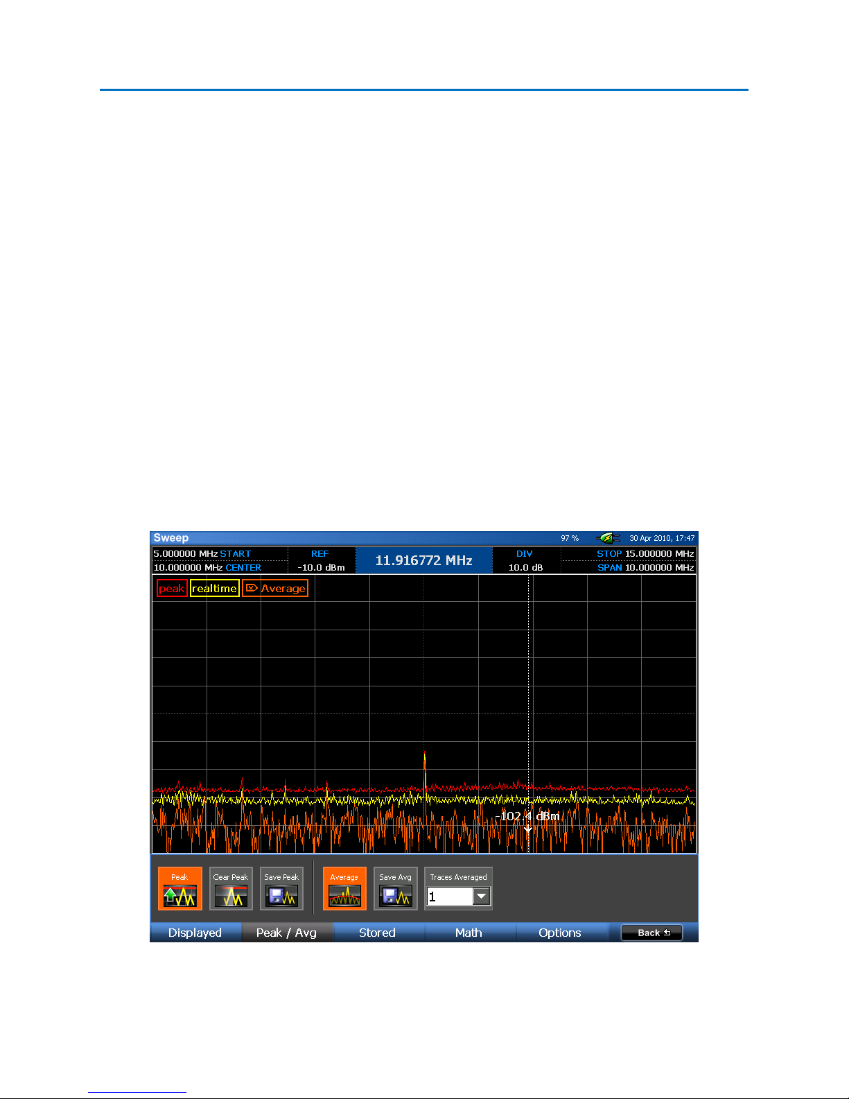
From the screenshot below, it is easy to see that the peak trace (in red) has the highest perceived noise
floor, then the real time trace (in yellow), and finally the average trace (in orange) displays the actual
noise floor.
41
Page 49
OPERATION
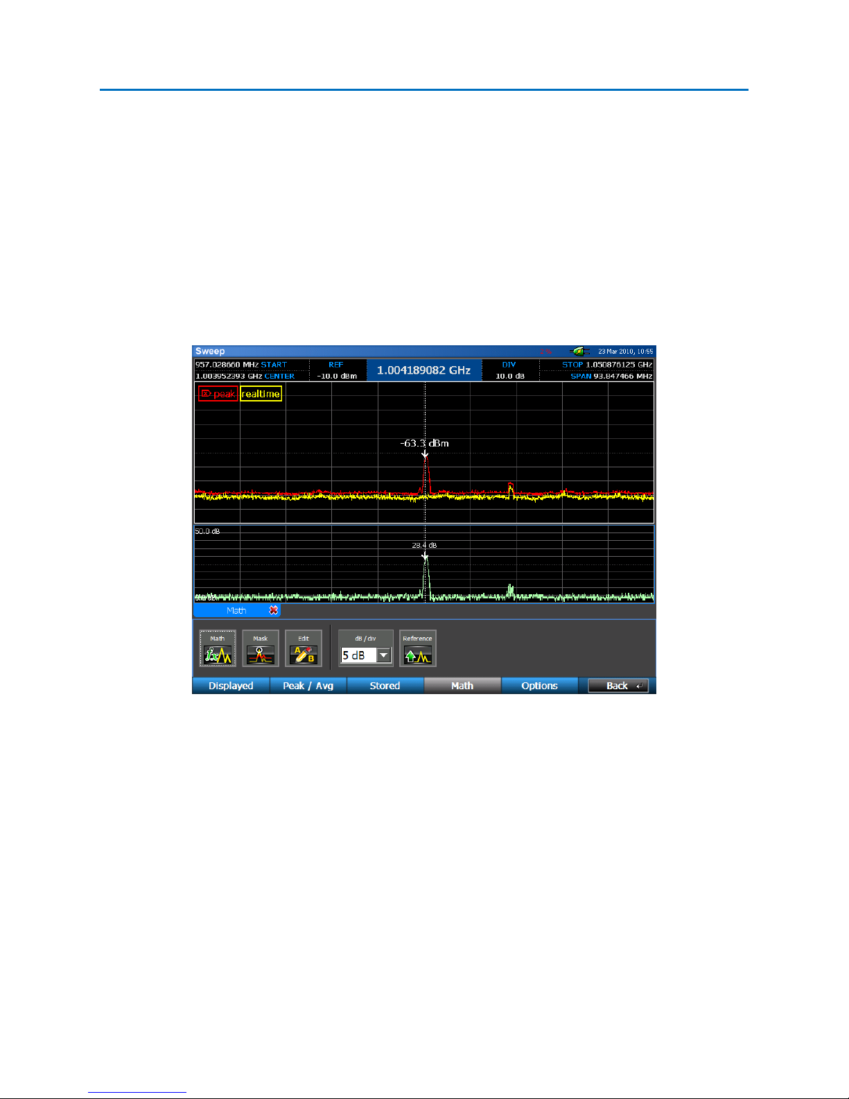
Math Trace
The OSCOR provides the ability to compare two different sets of trace data. Math traces can be
generated from the real time trace, peak trace, average trace, or up to 4 saved traces if they are
currently open on the OSCOR unit. The Math Trace allows a very quick view of the difference between
the Frequency Spectrum of two different locations or the same location at two different times, and is a
very reliable method for detecting sophisticated transmitters that are not continuous transmitters. This
mode is useful to determine the location of a transmitter within an environment by comparing the RF
spectrum of one room to another room.
Warning: It is important to understand that this function is not a true math A-B function. It only provides
the difference spectrum for signals in Trace A that are larger than the corresponding frequency in Trace
B. In other words, the math trace will not indicate signals in B that are larger than A. Therefore, to
highlight all differences between the two signals, it is important to generate two math traces, swapping
the order of the traces the second time.
42
Page 50
OPERATION
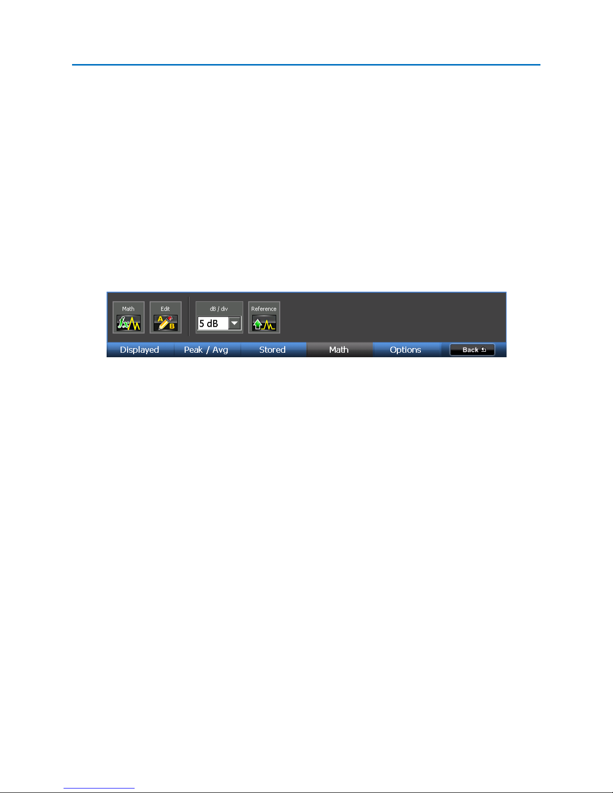
To Display a Math Trace:
1. From the Main Menu, select Traces or press F2.
2. From the Traces Sub-Menu, select Math or press F4.
3. Select the Math icon. Note: If a math trace has already been set up once during your current
session, you will need to use the Edit icon to change the math trace.
4. From the drop-down menus in the Edit Math Trace dialog box, select traces for Trace A and
Trace Band select OK. The math trace will open in a tabbed window below the spectral display.
The example below shows a comparison between the peak trace and real time trace.
Several other tasks related to the math trace can be performed from the Traces|Math Sub-Menu.
• Math – Once a math trace has been set up, pressing the Math icon again will hide the math
trace. Each subsequent press of the Math icon will toggle the display of the math trace. Only
one math trace can be displayed at a time.
• Mask – Compares the realtime trace to a stored mask trace and adds a signal to the signal list
when the difference exceeds a user defined threshold. This comparison is done on a sweep by
sweep basis. If the real time signal remains above the threshold then there is only one event
added to the list. If the realtime signal drops below the threshold and then exceeds the
threshold again, another event will be added to the signal list. The signal list table includes
frequency, power, bandwidth, timestamp, last seen timestamp and count information.
43
Page 51
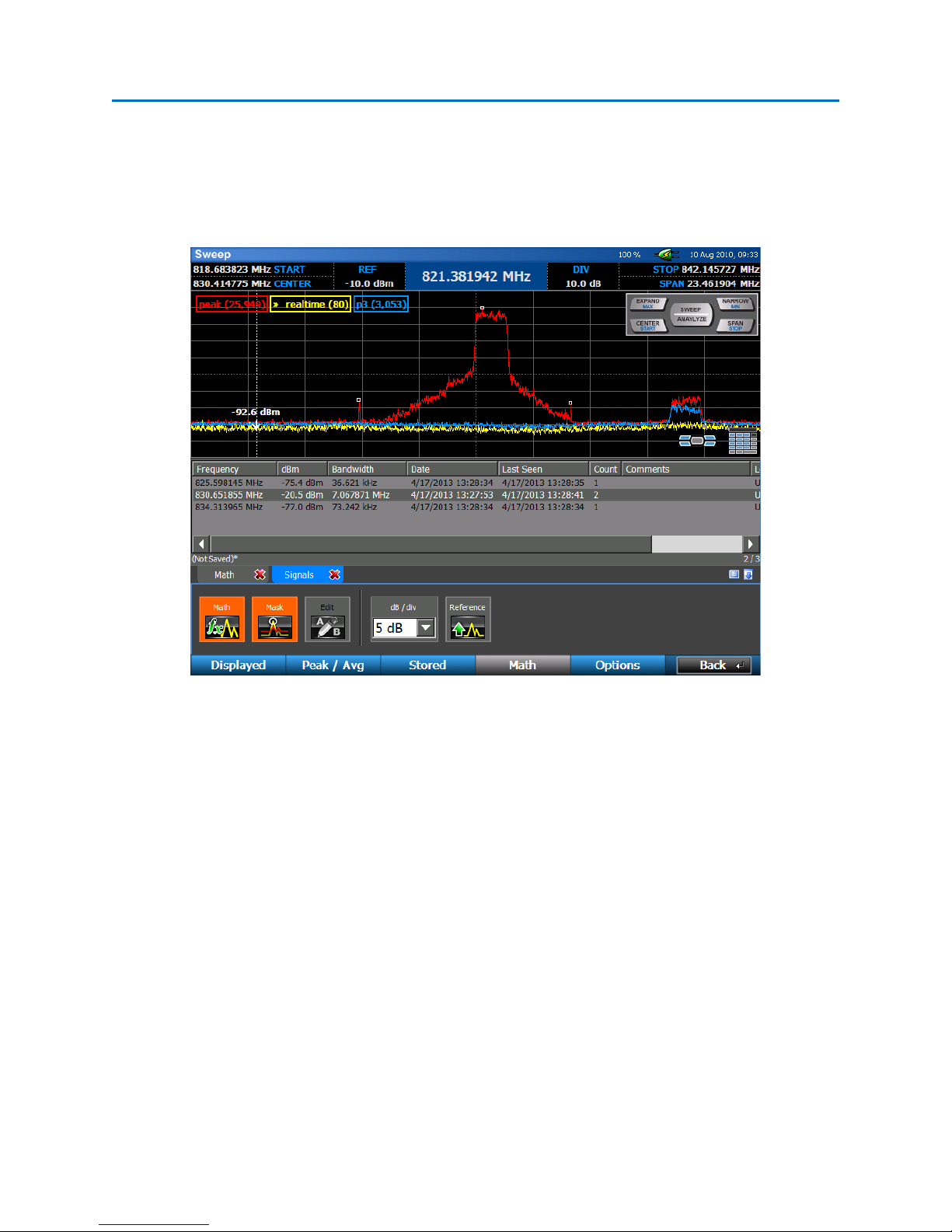
OPERATION
Note: While using the Mask function, you may notice some signals seem to automatically be
removed from the list. Some types of signals, such as frequency hoppers or FM transmitters
may initially appear as several distinct, closely spaced signals. Overtime, as the envelope of this
signal begins to fill in with peaks, the Mask function will automatically group these previously
recognized narrow band signals into one signal with a larger bandwidth.
Mask Example: Detecting the presence of a cell phone call
• Edit – Once a math trace has been set up, use the Edit icon to change what traces are used in
the Math Trace.
• dB / div – The dB/div drop down box allows you to change the scale of the math trace graph. By
default this is set to 5 dB per division.
• Reference – use the Reference Icon to change the reference level of the bottom of the math
trace graph. The reference level can be adjusted from -40 dB to 100 dB. To enter negative
reference values, select +/- on the virtual keypad or press the +/- key after entering the numeric
value.
44
Page 52
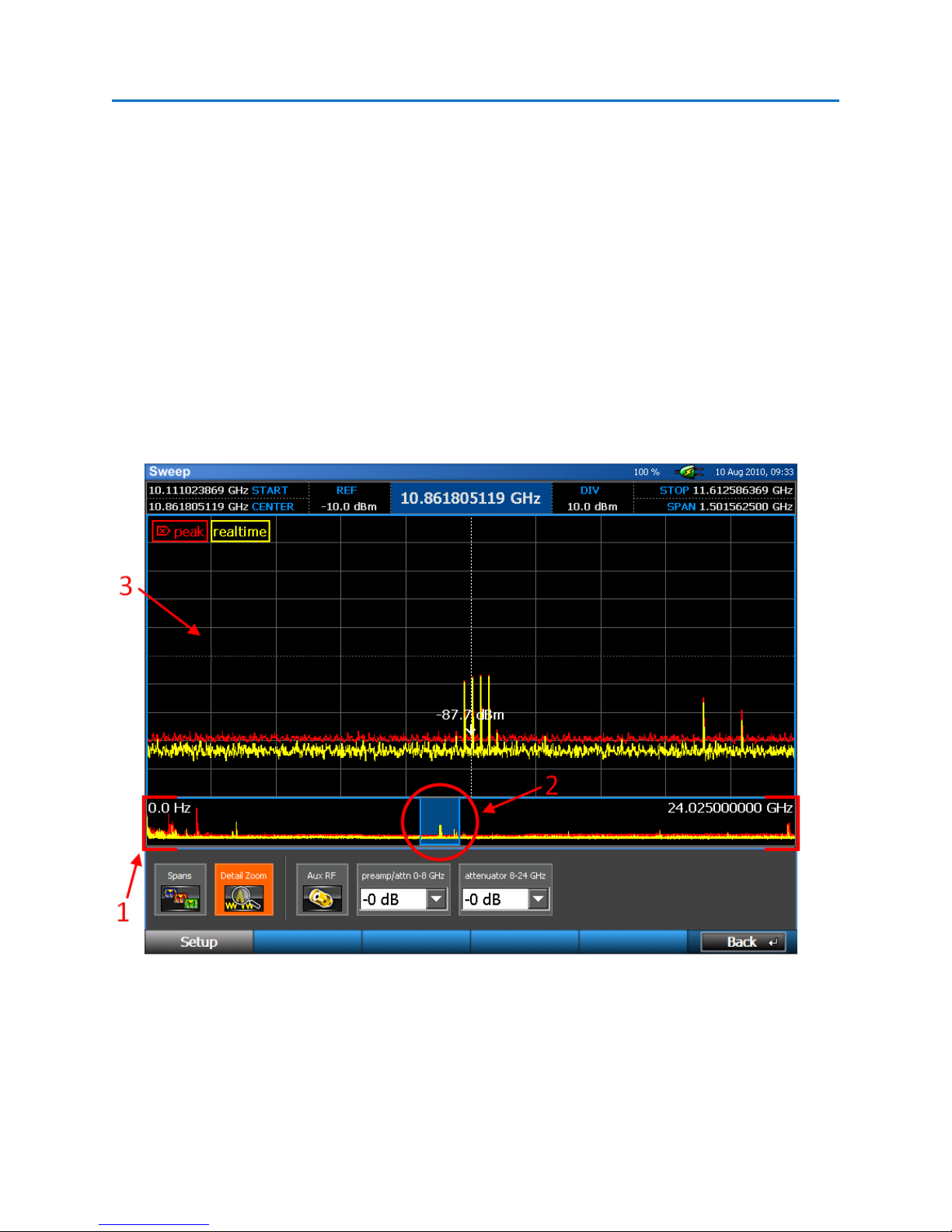
OPERATION
Detail Zoom
Up to this point, all methods described for navigating around the spectrum, i.e. narrowing or expanding
the span, changing start and stop frequencies, panning across the spectrum, etc…, have involved
changing the range the tuner is actually sweeping. What if you are interested in continuing to sweep
the full tuner range with the OSCOR collecting peak data for the full range, but you want to look at just a
specific portion of the spectrum in more detail? In this situation, you would use the Detail Zoom feature
on the OSCOR. To enable Detail Zoom on the OSCOR:
1. Set the range that you want the tuner to sweep (see page 31).
2. From the Main Menu, select Setup or press F1.
3. Select the Detail Zoom icon.
Detail Zoom Screen Elements
1. Spectral Thumbnail – The spectral thumbnail shows the range that the tuner is sweeping. Start
and stop frequencies for the tuner are displayed on the left and right sides of the spectral
thumbnail.
45
Page 53

OPERATION
2. Zoom Region – shows the portion of the tuner range that is displayed in the detail zoom
window.
3. Detail Zoom Window – When zoomed in on a portion of the tuner range, this window is where
you will view the zoomed portion of the spectrum.
Navigating within the Detail Zoom Window
When Detail Zoom is on, all of the spectral parameters at the top of the screen refer to the Detail Zoom
Window, not the range currently being swept by the tuner or the spectral thumbnail. Also, when detail
zoom is on, any changes made to the spectral parameters or any of the methods described previously
for navigating the spectrum will change only the detail zoom window; the tuner continues to sweep the
same range that was set when Detail Zoom was turned on. With Detail Zoom on, there is one additional
way to navigate the spectrum:
- Click & Drag – Thumbnail Pan: if the detail zoom window is set to a narrower span than the
spectral thumbnail (or tuner range), you can pan the current spectrum by clicking within the
zoom region (or highlighted portion of the spectral thumbnail) with the stylus or your finger and
dragging the highlighted portion to the left or right.
Setting Up the Tuner Range for Detail Zoom
The tuner range must be set up before Detail Zoom is entered. If you wish to change the tuner range
once detail zoom has been turned on, you must first disable Detail Zoom (select the Detail Zoom icon
within the Setup Sub-Menu so that it is not highlighted) and then adjust the tuner range.
WARNING: When Detail Zoom is turned off, the tuner range will be adjusted to the same range as the
detail zoom window. If you are collecting peak data for a specific tuner range, be sure to set the detail
zoom window to that range before switching detail zoom off.
By default, the tuner range in Detail Zoom mode is established by how the tuner is setup when Detail
Zoom is entered. It is possible to have the tuner always switch to a specific preset when Detail Zoom is
entered:
1. From the Main Menu, select Setup or press F1.
2. Select the Spans icon.
3. At the top of the dialog box, switch the Detail Zoom Tuner Setting from “Set to Screen” to
“Preset Span” by selecting Preset Span.
4. From the drop down box next to Preset Span, select a span.
46
Page 54
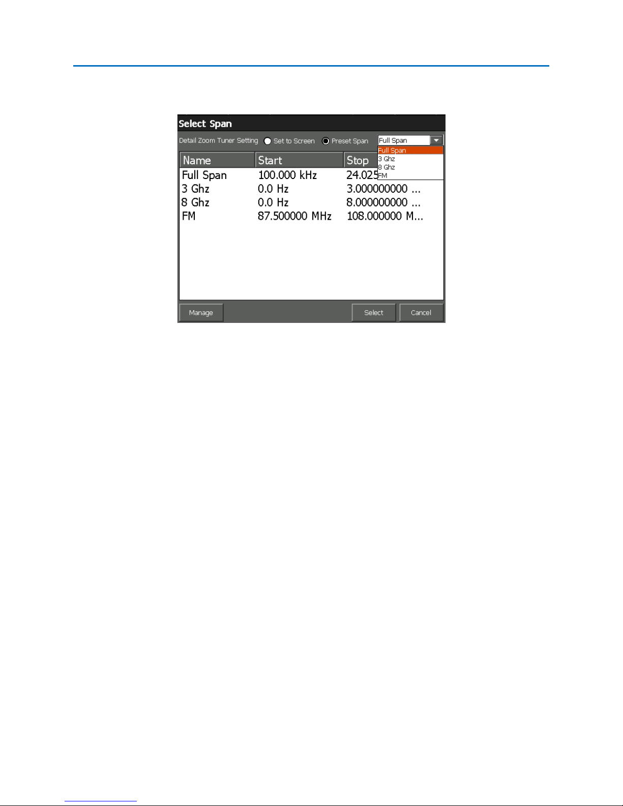
OPERATION
To create a new preset span for the detail zoom tuner setting, you must first create a new custom tuner
span (see page 26).
Note: Detail Zoom can also be accessed from the Traces | Displayed Sub-Menu.
47
Page 55
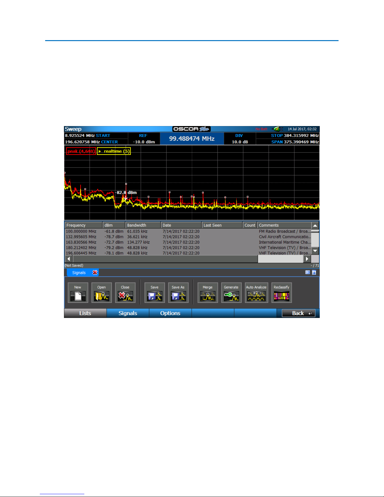
OPERATION
Signals
Signal Lists
A signal list allows you to store and recall frequencies of interest along with additional information such
as signal amplitude, bandwidth, threat level, location, and any other comments which may be
important. With the OSCOR, you have the capability to automatically generate signal lists, merge signals
from multiple databases, add or delete signals from an existing database, or edit the information for any
given signal – all on the OSCOR unit itself.
The signal list parameters that are automatically identified by this functionality include:
• Frequency –Peak of the signal within the measured bandwidth window
• dBm – Signal Level in dBm
• Bandwidth – The measured Bandwidth of the signal between the signal threshold levels (this
bandwidth may vary depending on the modulation and detected signal characteristics)
• Date – The date and time the signal was identified in the signal list. Note: This is not the actual
time that a signal was detected within a peak trace.
• Last Seen, Count – these fields are automatically populated by the Mask function (see page 43).
• Location, Threat, Comments – these are fields that can be edited by the user for later analysis.
48
Page 56

OPERATION
Generating and Saving a Signal List
To generate a signal list:
1. From the Main Menu, select Signals or press F3.
2. The Lists Sub-Menu should be visible. If it is not, select Lists or press F1.
3. From the Lists Sub-Menu, select the Generate icon.
4. A dialog box will appear asking you to select from any currently displayed traces. Any signals on
the trace that you select with an amplitude greater than the set threshold will be added to the
generated signal list. Select the desired trace and press OK.
5. A menu will appear to specify the signal level threshold. The OSCOR unit evaluates the noise
floor and identifies all of the signals that exceed the noise floor by this threshold amount. Set
the desired threshold level and press OK.
6. The generated signal list will appear in a tabbed window below the spectral display. Each signal
generated will be tagged with a small square marker in the spectral display.
7. From the Lists Sub-Menu, select the Save icon. From the Save Dialog Box, select a location and
name for the saved signal list. Select OK or press F5.
Signal Lists are saved in a comma-separated values, or CSV, file format so that they are easily exported
and read by spreadsheet programs, such as Microsoft Excel, or text editors, such as Notepad. The file
extension used for a signal list file is “.signals”; however, the underlying format is CSV. To open a signal
list in Microsoft Excel, or other spreadsheet program, and maintain the tabular properties of the signal
list it may be necessary to specify how the file is delimited when opening the file. Consult the manual
for your particular spreadsheet program for details. Caution: Editing a signal list file with another
program could affect reopening the file on the OSCOR unit.
Note: Signal Lists are only generated from the viewed spectrum. To generate a signal list based on the
entire 24 GHz spectrum (or 8 GHz for 8 GHz models) ensure that the entire spectrum is shown by
49
Page 57

OPERATION
pressing SHIFT + EXPAND. If Detail Zoom is on, then the signal list will be generated from the spectrum
shown in the spectral thumbnail.
Frequency Allocation Information
When generating a signal list, the OSCOR will automatically populate the comments field with
information about the frequency band that a signal might be a part of for the currently selected ITU
region. This information contains known regulatory or other uses of given frequency bands. Depending
on the frequency there may be multiple allocations given.
The frequency allocation information is also provided anytime that a signal is added to an existing signal
list.
Note: The frequency allocation information is provided as reference from the International
Telecommunication Union (ITU) database per their band assignments. It should not be used to
determine if a signal is or is not a threat. It is the user's responsibility to investigate and analyze to
determine whether it is friendly or a threat.
Setting the ITU Region
To ensure that accuracy for the frequency allocation information, be sure to set the ITU region.
1. From the Main Menu, select Signals or press F3.
2. From the Signals Sub-Menu, select Options or press F3.
3. From the Options Sub-Menu, select a value from the ITU Region drop-down box.
a. ITU Region 1 comprises Europe, Africa, the former Soviet Union, Mongolia, and the
Middle East (west of the Persian Gulf).
b. ITU Region 2 covers the Americas, Greenland and some of the eastern Pacific Islands.
50
Page 58

OPERATION
c. ITU Region 3 contains most of Asia (not including the former Soviet Union) and most of
Oceania.
d. FCC is a special case of ITU Region 2 for US regions that fall under FCC regulations
For more information, see https://en.wikipedia.org/wiki/ITU_Region and http://www.itu.int
Note: Changing the ITU Region while a signal list is open will not reclassify all of the signals in the signal
list. You must use the Reclassify operation (see next section) to update the signal list.
Reclassifying a Signal List
If the ITU Region is not set correctly when a signal list is generated, the frequency allocation information
in the comments field may not be accurate for your region. It is possible to redo the frequency
information for your region after a signal list is generated without having to regenerate the signal list
again.
1. Ensure that ITU Region is set correctly (see previous section).
2. Ensure that the signal list you want to reclassify is open on the OSCOR.
3. From the Main Menu, select Signals or press F3.
4. The Lists Sub-Menu should be visible. If it is not, select Lists or press F1.
5. From the Lists Sub-Menu, select the Reclassify icon.
6. A dialog box will appear asking you to confirm that you want to reclassify all signals in the signal
list according to the currently selected ITU region. Select Yes or press F5.
NOTE: Reclassifying a signal list will overwrite all comments in the signal list. Any comments that you
have added through manual edits WILL BE LOST.
51
Page 59

OPERATION
Opening or Closing a Signal List
1. If you are not already in the Signals|Lists Sub-Menu, from the Main Menu select Signals|Lists.
2. From the Lists Sub-Menu, select the Open icon. The open dialog box will appear.
3. After navigating to the media where your signal list is located, select your previously saved
signal list and select OK or press F5.
4. To close any open signal list, select the Close icon from the Signals | Lists Sub-Menu or select the
red ‘x’ on the tabbed signal list window. Both the displayed signal list and the markers displayed
in the spectral graph will disappear.
Note: A signal list can be open at the same time as a Sweep Mode RSSI locator window, a live raster
waterfall, or a math trace. If more than one of these items is open, these windows will be tabbed.
Select a tab to display the respective window.
Merging Signal Lists
With the OSCOR, you are able to merge multiple signal lists in the unit itself. However, you must be
careful with this function because it is relatively easy to corrupt a signal list with duplicates of the same
signals.
1. Open one of the signal lists that you would like to merge.
2. If you are not already in the Signals | Lists Sub-Menu, from the Main Menu select Signals | Lists.
3. From the Lists Sub-Menu, select the Merge icon. The open dialog box will appear.
4. From the open dialog box, choose another signal list that you would like to merge and select OK
or press F5. This signal list will now open and will be merged with the signal list that was already
open on the unit.
5. You can continue merging additional signal lists by repeating steps 3 and 4. Be sure to select the
Merge icon and not the Open icon.
6. When you are finished working with the merged signal list, be sure to save it for future
reference.
Adding or Removing Signals from Signal Lists
Signals can be added to or removed from any open signal list. If no signal list is currently open and you
add a signal, a new list is created with the added signal. This list must be saved before it is closed or
before you open another list, if you want to be able to recall it later.
52
Page 60

OPERATION
1. Position the cursor on the frequency of the signal that you would like to add to the list. When
adding signals, the OSCOR will search for the largest peak in the area immediately surrounding
the cursor. For increased accuracy narrow in on the cursor position before adding the signal.
2. From the Main Menu, select Signals or press F3.
3. From the Signals Sub-Menu, select Signals or press F2.
4. Select the Add icon. If a signal list is already open, the signal will be added to this list. If no
signal list is open, a new list will be created with this signal added.
5. Continue adding signals by repeating these steps.
6. To remove a signal, select the signal you wish delete from the displayed signal list with the
stylus.
7. From the Signal Sub-Menu, select the Remove icon. The selected signal will be removed.
8. When you are finished editing your signal list, be sure to save it, if you want to be able to recall
it later.
Editing Signals
Additional information can be stored with each signal in your signal list, such as whether the signal is
known or a possible threat, a location, and any comments that you want to add. The frequency,
amplitude and bandwidth values can also be tweaked. To edit a signal:
1. Select the signal in the signal list with the stylus or your finger.
2. If you are not already in the Signals | Signals Sub-Menu, from the Main Menu select Signals |
Signals.
3. From the Signals Sub-Menu, select the Edit icon.
4. The Edit Signal Dialog Box will appear.
5. Edit information for the signal and press OK.
It is also possible to edit a signal list without switching to the Signals Sub-Menu:
1. Tap the signal list with the stylus or your finger to highlight the signal you want to edit.
2. Press the OK button.
3. Select “Edit Signal” from the context menu that appears. Edit information for the signal and
press OK.
53
Page 61

OPERATION
Hiding/Showing the Signal List and Markers
To hide the signal list and/or the markers which are displayed by default on the spectral graph when a
signal list is generated:
1. If you are not already in the Signals Sub-Menu, from the Main Menu select Signals or press F3.
2. From the Signals Sub-Menu, select Options or press F3.
3. From the Options Sub-Menu, select the Show List icon. The Signal List will be hidden. Select the
Show List icon again to display the list.
4. From the Options Sub-Menu, select the Markers icon. The Signal Markers on the graph will be
hidden. Select the Markers icon again to display the markers.
Notes
- Hiding the Signal List does not close the signal list. A signal list can be hidden without being
saved. Ensure any signal list that is hidden is saved before shutting down the unit or the data
from the signal list could be lost.
- The tab pane can also be collapsed to hide the signal list by tapping the downward arrow in the
lower right corner. To expand the tab pane select the arrow again.
Traversing a Signal List
Controls exist for easily moving the cursor from one signal to the next within a signal list. After
generating a signal list:
1. If you are not already in the Signals Sub-Menu, from the Main Menu select Signals or press F3.
2. From the Signals Sub-Menu, select Signals or press F2.
3. From the Signals Sub-Menu, select the Closest icon. If the cursor is not already positioned on a
signal marker it will move to the closest one. If the Signal List is displayed, the signal will be
highlighted in the list.
54
Page 62

OPERATION
4. From the Signals Sub-Menu, select the Next icon. The cursor will move to the signal in the Signal
List with the next highest frequency.
5. From the Signals Sub-Menu, select the Previous icon. The cursor will move to the signal in the
Signal List with the next lowest frequency.
To move the cursor directly to a signal in a displayed signal list:
1. Double tap the signal in the signal list with the stylus.
or
1. Tap the signal list with the stylus or your finger to highlight the signal you want to edit.
2. Press the OK button.
3. Select “Go To Signal” from the context menu that appears.
Notes:
• The info bar at the bottom of the signal list displays the file path for the signal list or it will
indicate “Not saved” if the currently displayed signal list is not saved.
• The total number of signals in the list is displayed on the right side of the info bar. If one of the
signals in the list is highlighted, the order number of the highlighted signal will also be displayed.
• By default the signal list is sorted by frequency. To sort a signal list by another parameter, tap
one of the column headings at the top of the signal list.
55
Page 63

OPERATION
Auto Analyze
After a signal list has been generated, the Auto Analyze function will automatically step through each
signal in the signal list fine tuning main carrier frequencies, bandwidth measurements, and determining
whether or not the signal correlates with room audio. Frequency and bandwidth determinations that
are made during signal list generation in Sweep Mode are subject to the resolution bandwidth
limitations found in Sweep Mode. The Auto Analyze function does a single frequency signal analysis on
each signal in a signal list and will make small adjustments to frequency and bandwidth values to more
accurately reflect the true main carrier frequency and bandwidth of the signal. For any analog signals
found in the list, the Auto Analyze function will make a determination of whether or not the
demodulated audio from the signal correlates with room audio. If it does, it will add this information to
the Threat column in the signal list. A manual correlation function is also available on the OSCOR unit
(see page 77).
To Auto Analyze a Signal List:
1. Open an existing signal list (see page 52) or generate a signal list (see page 49).
2. If you are not already in the Signals Sub-Menu, from the Main Menu select Signals or press F3.
3. The Lists Sub-Menu should be visible. If it is not, select Lists or press F1.
4. From the Lists Sub-Menu, select the Auto Analyze icon. The Auto Analyze Setup dialog box will
appear.
5. The following options are available from the Setup dialog:
a. Envelope Dwell Time – this configures the amount of time that the Auto Analyze
function will dwell on each signal to make bandwidth determinations. The following
options are available from the drop down box: 1 second, 3 seconds, and 5 seconds. The
56
Page 64
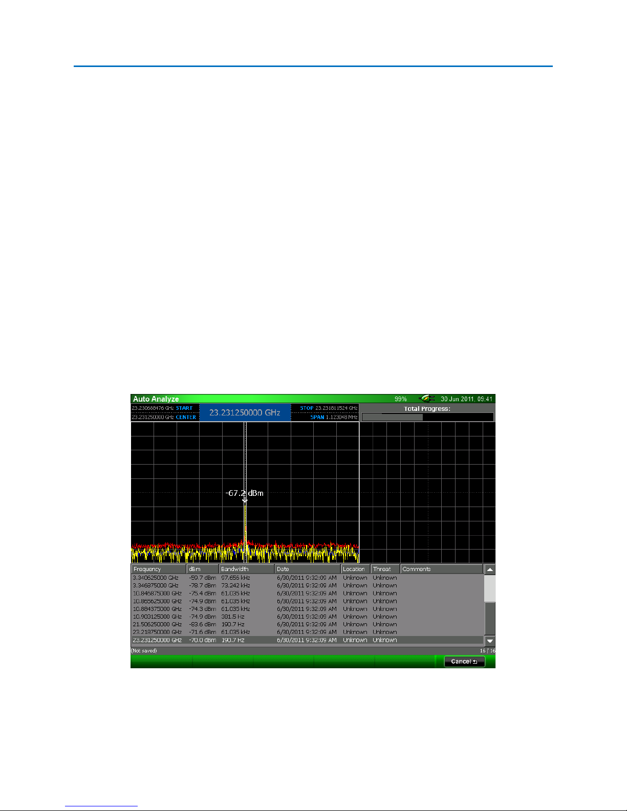
OPERATION
longer the dwell time is, the more accurate the bandwidth value will be, however, the
overall time for the Auto Analyze process will be longer. The default value for Envelope
Dwell Time is 3 seconds.
b. Enable Noise Output – selecting this option will enable the white noise generator and
unmute the audio. The white noise generated by the OSCOR unit will aid in correlation
of analog signals and in the bandwidth measurement of FM signals.
c. Enable Signal Correlation – if this option is selected the OSCOR unit will attempt to
demodulate each signal and determine whether the demodulated audio correlates with
room audio.
d. Correlation Dwell Time – this configures the amount of time that the Auto Analyze
function will dwell on each signal to make correlation determinations. The following
options are available from the drop down box: 1 second, 3 seconds, and 5 seconds. The
longer the dwell time is, the more accurate the correlation determination will be,
however, the overall time for the Auto Analyze process will be longer. The default value
for Correlation Dwell Time is 3 seconds.
6. After configuring the Auto Analyze setup, Select Start to begin the Auto Analyze process or
select Cancel to disregard the setup and return to the previous screen.
The Auto Analyze function first steps through each signal in the signal list analyzing the Main Carrier
Frequency and the Bandwidth of each signal.
A progress bar at the top right of the screen gives a visual indication of the Auto Analyze progress. The
top left of the screen features a spectral representation of each signal as Auto Analyze progresses
through the signal list. The signal list is displayed across the bottom of the screen.
57
Page 65

OPERATION
If you chose to enable Signal Correlation when setting up Auto Analyze, the Auto Analyze function will
step through the signal list a second time to make a determination of whether or not the signal
correlates with room audio.
nd
During this 2
screen. If a signal does correlate with room audio, then the text “Correlates” is added to the Threat field
for that signal in the signal list.
After using the Auto Analyze feature, always save the open signal list (see page 49) to ensure that any
changes are not lost.
Note: The Auto Analyze function is also available in Analyze Mode from the Signals | Lists Sub-Menu.
part of the process, a correlation graph will be displayed at the top right corner of the
58
Page 66
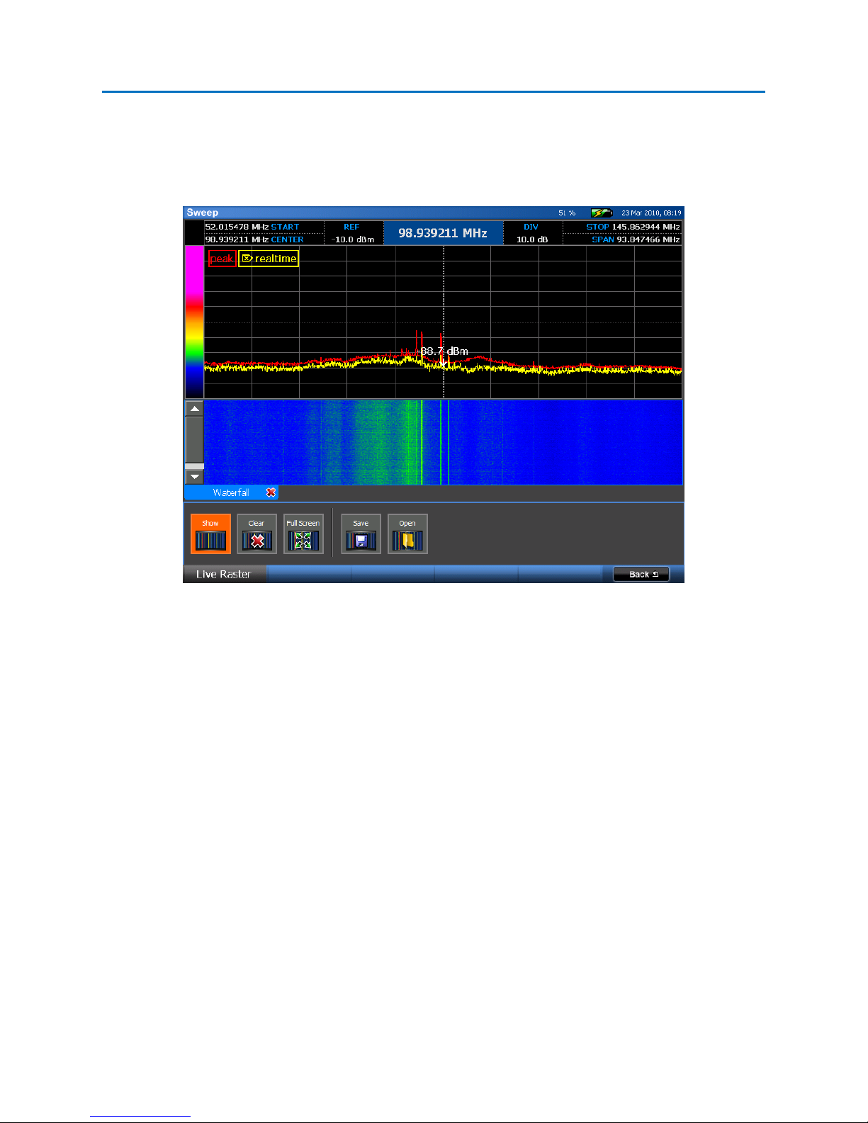
OPERATION
Live Raster Waterfall
The Live Raster feature on the OSCOR captures a series of traces and displays them in a waterfall format.
This is a quick way to observe the RF spectrum over a period of time and easily identify intermittent
transmissions such as burst transmitters.
Opening, Clearing, and Closing a Live Raster Waterfall
1. From the Main Menu, select Waterfall or press F4.
2. If the Live Raster Sub-Menu is not already displayed, select Live Raster or press F1.
3. From the Live Raster Sub-Menu, select the Show icon. A Live Raster Waterfall window will be
displayed and you will begin to see traces displayed as they are captured in a waterfall format.
4. To clear the waterfall display, from the Live Raster Sub-Menu, select the Clear icon. The
waterfall data will be erased and the OSCOR unit will begin collecting traces again for a new
waterfall display.
5. Once you have collected more than one screen full of data, use the scroll bar to see data off
screen.
6. To close the Live Raster Waterfall data, select the Show icon from the Live Raster Sub-Menu or
click the red ‘x’ on the tabbed window. The Live Raster Waterfall window will be hidden and
data collection will be paused until the waterfall window is displayed again.
59
Page 67

OPERATION
Notes
- The span and bandwidth of the spectral display can be changed while viewing a Live Raster
Waterfall. However, whenever the spectral display is changed, the waterfall data will be cleared
and a new waterfall will begin, unless Detail Zoom (see page 45) is turned on.
- The speed with which the Live Raster Waterfall data is captured and displayed will vary
depending on the span of the RF spectrum; the narrower the span, the more quickly the data
will be captured and displayed.
- Once the size of the Live Raster Waterfall has exceeded the memory buffer size, older traces will
be discarded for each new trace added.
- If the realtime trace is not displayed, turning on the Live Raster Waterfall will also automatically
turn on the realtime trace.
Viewing a Live Raster Waterfall Full Screen
The waterfall display from a Live Raster Waterfall can be viewed full screen.
1. While the Live Raster Waterfall is displayed and collecting date, select the Full Screen icon from
the Live Raster Sub-Menu.
2. To close the full screen waterfall display and return to normal viewing, select Close or press F6.
Saving a Live Raster Waterfall
The waterfall display from a Live Raster Waterfall can be saved as a .png file for inserting into reports.
1. While the Live Raster Waterfall is displayed and collecting data, select the Save icon from the
Live Raster Sub-Menu.
2. In the dialog box that appears, select a location (either a USB flash drive or compact flash card)
and type a file name for the stored .png file. Select OK or press F5.
Notes
- The Live Raster Waterfall cannot be saved while viewing full screen; you must return to normal
viewing in order to have access to the Save icon.
Opening a Saved Live Raster Waterfall
Previously saved Live Raster Waterfalls can be opened on the OSCOR unit for review.
3. From the Main Menu, select Waterfall or press F4.
60
Page 68

OPERATION
4. If the Live Raster Sub-Menu is not already displayed, select Live Raster or press F1.
5. From the Live Raster Sub-Menu, select the Open icon.
6. From the dialog box that appears, navigate to any attached storage, such as a compact flash
card or a USB thumb drive, select a saved peak trace, and choose OK or press F5. It may be
necessary to change the file type (either .png or .bmp) in the dialog box to view previously
stored waterfalls.
Modifying the Waterfall Color Gradient
The color gradient used for the Live Raster Waterfall can be customized by selecting colors for key
amplitude levels.
1. Tap the color gradient shown at the top left hand side of the Live Raster Waterfall screen. The
Waterfall Colors dialog box will appear. On the left side of the dialog box are two color controls
for selecting colors. The slider to the far left is used to select a hue. The color field to the right
of the hue slider is for adjusting the saturation and brightness of the selected hue. On the right
side of the dialog box is a gradient editor for mapping specific colors to key amplitude levels of
the waterfall color gradient.
2. To remove existing colors from the current color gradient, highlight the corresponding color
marker from the gradient editor on the right side of the dialog box by selecting it with the stylus,
then select the “-” marker at the bottom of the control.
3. To add a color to the color gradient, select the “+” marker at the top of the gradient editor on
the right side of the dialog box. This will place a new color marker at the center of the gradient
editor. Drag the new color marker up or down the gradient editor to modify the dBm value
represented by the color. Edit the color of the marker by using the color controls on the left
side of the dialog box.
61
Page 69

OPERATION
4. To edit an existing color in the color gradient, highlight the corresponding color marker on the
gradient editor with the stylus. Drag the color marker up or down the gradient editor to modify
the dBm value represented by the color. To edit the color of the selected marker, use the color
controls on the left side of the dialog box.
5. To return to the default color gradient, select Default from the list of preset gradients on the left
side of the dialog box.
6. After all changes have been made, select OK to enable changes.
62
Page 70
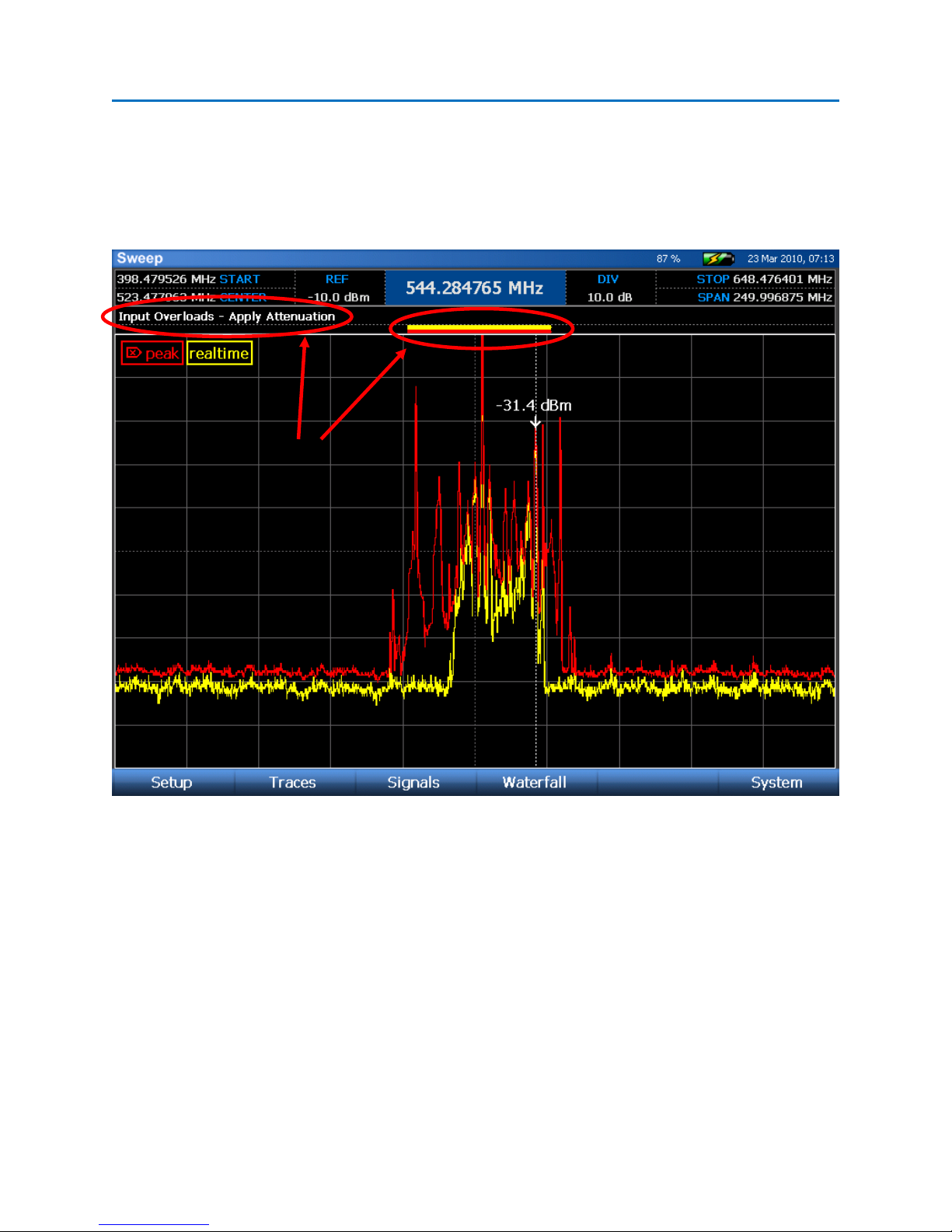
OPERATION
Overload Indicators
Receiver Overload – Sweep Mode
Due to the nature of digital receivers, very strong signals can have an overloading effect on the receiver
circuitry, resulting in intermodulation distortion and/or large spurs appearing at aliased frequencies. To
assist in these situations, the OSCOR is equipped with overload indicators to alert the user that an
overload is occurring.
In the screenshot above, a very strong signal at 525 MHz is causing an overload situation. As a result, it
appears that there are many signals in the area around this frequency, however, these are false spurs
and are due to the receiver overload condition. The red & yellow bars in the row above the spectrum
are indications that receiver overload is occurring in both the peak (red) trace and the realtime (yellow)
trace. Also, the text “Input Overloads” appears above the spectrum with the words “Apply Attenuation”
flashing as an additional warning.
To correct the receiver overload, apply the smallest amount of input attenuation (see page 27) that
prevents the overload condition, so that the overload indicators disappear. Once this condition is
corrected, the false spurs will also disappear.
63
Page 71

OPERATION
The screenshot above shows the same signal, but with 10dB of input attenuation applied. The overload
indicators have disappeared as well as the false spurs.
Overload information is stored when peak traces are saved. The screen shot above shows a blue bar
above the spectrum to indicate that the stored trace (which is displayed in blue) has an overload
condition.
64
Page 72

OPERATION
ANALYZE MODE
Analyze Mode changes the operation of the OSCOR from a sweep function to a single frequency signal
analysis. The resolution bandwidth in Analyze Mode varies depending on the zoom level; it improves as
you narrow the span. Analyze Mode will demodulate an analog AM, FM, or video signal.
To enter Analyze Mode:
1. Move the cursor to the frequency of interest (see page 33.)
2. Press the SWEEP/ANALYZE button.
3. The OSCOR unit will enter Analyze Mode.
Note: Analyze Mode can also be entered by using the Analyze icon found in Sweep Mode’s Signals |
Signals menu.
Analyze Mode Screen Elements
• Spectral Graph – displays a portion of the frequency spectrum, centered on the frequency
where the cursor was located before entering Analyze Mode.
• Oscilloscope – an oscilloscope view of the demodulated signal. If video demodulation is not
turned on, the oscilloscope will be positioned just below the spectral graph and will span the
entire width of the display.
65
Page 73

OPERATION
• Video Display – displays demodulated video. By default, video is not displayed when you enter
Analyze Mode. Video Demodulation must be turned on by selecting the Video icon in the
Demod Sub-Menu within Analyze Mode. (Not shown above)
Setting up the Analyze Mode Display
Several items on the Analyze Mode display can be customized depending on the information that needs
to be seen on the screen:
Adjusting the Reference Level:
1. Select the reference level indicator “REF” at the top left of the screen with the stylus.
2. With the reference level indicator highlighted, enter a new reference level with the numeric
keypad or scroll through possible values using the rotary dial.
Adjusting the dBm per screen division:
1. Select the dBm per screen division indicator “DIV” at the top right of the screen with the stylus.
2. With the “DIV” indicator highlighted, tap a second time with the stylus to display a drop down
list with possible values. You can also use the rotary dial to scroll through possible values once
the “DIV” indicator is highlighted.
Notes: To reset the reference level and the dBm/div value to the default, press the OK button and
select Default Range from the context menu that pops up.
Demodulating an analog signal in Analyze Mode
After entering Analyze Mode, you must specify the type of demodulation and the filter bandwidth to
use. By default, FM audio demodulation with a 200 kHz bandwidth is selected when first entering
analyze mode. To change the demodulation scheme:
1. Within Analyze Mode, if you are not already in the Demod Sub-Menu, select Demod or press F1.
2. For AUDIO demodulation schemes:
a. Audio demodulation is on by default when first entering analyze mode. If video
demodulation has been turned on, press the Video icon to toggle it off and return to
audio demodulation.
b. Select the type of Audio Demodulation that you want to use: AM or FM
c. Select the filter bandwidth that you wish to use: 12.75 MHz, 6.375 MHz, 800 kHz, 200
kHz, 12.5 kHz, 6.25 kHz, 2 kHz
66
Page 74

OPERATION
d. By default, audio is muted when Analyze Mode is entered. Press Mute or adjust the
volume using the Vol^/v keys to hear the demodulated audio through the OSCOR unit’s
speakers. You can also use headphones to listen to the demodulated audio. Plugging
headphones into the headphone output will automatically mute the built-in speakers.
e. For improved clarity, adjust the Gain value.
The analyze screen for Audio Demodulation consists of two plots. The upper plot is the frequency
spectrum. The lower plot is an oscilloscope view of the demodulated signal. Notice that the cursor
in Analyze Mode is slightly different from Sweep Mode. The dotted vertical line represents the
frequency of the main carrier. This value is displayed at the top center of the screen. The solid lines
to either side of the dotted line represent the limits of the filter bandwidth selected in step 2c
above.
3. For VIDEO demodulation schemes:
a. From the Demod Sub-menu, select the Video icon to change the demodulation scheme.
b. The OSCOR will automatically determine the video format of the signal that it is tuned
to. It has the capability of decoding most variants of NTSC, PAL, & SECAM systems.
c. Select the type of demodulation that you want to use: AM or FM
d. Select the filter bandwidth that you wish to use: 12.75 MHz, 6.375 MHz, 800 kHz, 200
kHz
e. The volume of the demodulated audio can be adjusted using the Vol ^/v keys on the
OSCOR unit and can be muted with the Mute key.
f. For improved clarity, adjust the Gain value. You may find it helpful to use the
oscilloscope display to assist with adjusting the gain. Adjust the gain until the
demodulated video signal is easily seen on the oscilloscope at a good level without any
clipping.
g. For video signals with an inverted sync pulse, the OSCOR provides the option of
inverting the video signal. If you have adjusted the gain in the previous step using the
oscilloscope so that the video signal is at a good level, but the OSCOR is still not
demodulating any video, try toggling the Invert icon in the Demod Sub-Menu to get the
video signal to tune in.
67
Page 75
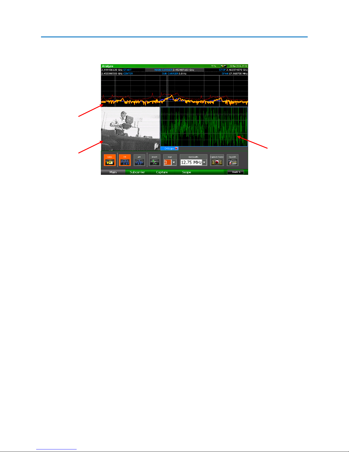
OPERATION
The analyze screen for Video Demodulation consists of the same two plots as the screen for Audio
Demodulation, but adds a third element: a window for displaying demodulated video.
spectral graph
Video Display
oscilloscope
Changing the Scope Display in Analyze Mode
The display can be modified to suit your particular application.
1. From the Analyze Mode Menu, select Demod or press F1.
2. From the Demod Sub-Menu, select Scope or press F4. The Scope Sub-Menu will be displayed.
The controls on the left side of the sub-menu pertain to the oscilloscope view for the main
carrier demodulation. The controls on the right side of the sub-menu pertain to the oscilloscope
view for subcarrier demodulation (see page 72).
3. From the Scope Sub-Menu, select the Demod Scope icon to toggle the display of the oscilloscope
view.
4. From the Scope Sub-Menu, select the Untrig Roll icon (on the left side of the sub-menu) to
change the scope trigger. With each press of the Untrig Roll icon the unit will cycle through the
available scope triggers: Rising Edge, Falling Edge, and Untriggered Roll.
5. The displayed grid can also be varied to optimize signal analysis. From the Time Div drop down
list that appears on the left side of the Scope Sub-Menu, select a value for the frequency of the
vertical grid lines.
6. From the Amp Div drop down list that appears on the left side of the Scope Sub-Menu, select an
amplification level for the horizontal grid lines: 1x, 2x, or 5x.
68
Page 76

OPERATION
Setting a Squelch Level for Demodulated Audio
The squelch control will allow you to suppress demodulated audio output when the carrier of the
currently tuned signal drops below a set threshold. This will prevent you from hearing white noise
when, for example, demodulating the audio from a two way radio and no transmission is being sent. To
set the squelch level:
1. From the Analyze Mode Menu, select Demod or press F1.
2. Select the Squelch icon. The audio, if previously muted, will un-mute and a horizontal cursor
representing the squelch level will appear on the spectral graph.
3. Adjust the squelch level using the rotary knob. Ideally, this level should be set just above the
noise floor so that when the audio signal drops into the noise floor, the audio is muted, but
whenever an audio signal is present, you are able to hear the demodulated audio.
Recording and playback of demodulated audio
The OSCOR has the capability of recording demodulated audio as a .wav file for later playback or for
analysis on another piece of equipment, such as a PC.
To capture demodulated audio using Quick Record:
Quick Record enables the user to quickly record up to 30 seconds of audio without first having to adjust
the recording properties.
1. While demodulating an analog audio signal in Analyze Mode, from the Analyze Mode Menu,
select Demod or press F1 to enter the Demod Sub-Menu.
2. From the Demod Sub-Menu, select Capture or press F3.
3. From the Capture Sub-Menu, select the Quick Record icon. The OSCOR unit will begin capturing
audio and the Quick Record icon will change to a Stop Recording icon.
4. To stop recording the audio at any point, select the Stop Recording icon. After 30 seconds of
audio have been captured, the OSCOR unit will automatically stop recording. Once the audio
recording has stopped, a dialog box will appear on screen.
5. In the dialog box that appears, select a location (either a USB flash drive or compact flash card),
type a file name for the stored audio file and press OK. The OSCOR unit will save the captured
audio in the specified location.
69
Page 77

OPERATION
To record longer durations of demodulated audio:
Quick Record only allows capture of up to 30 seconds of audio. To record for longer durations it will be
necessary to use the Record Audio icon and setup the location for file saving beforehand.
1. While demodulating an analog audio signal in Analyze Mode, select the Record Audio icon from
the Demod| Capture Sub-Menu. A dialog box will appear on screen.
2. In the dialog box that appears, select a location (either a USB flash drive or compact flash card)
for the stored audio file, type a file name and press OK. The OSCOR unit will begin saving the
captured audio to this specified location.
3. During recording the Record Audio icon will be highlighted in orange. To stop recording the
audio at any point, select the Record Audio icon again so that it is no longer highlighted.
To playback previously recorded audio:
1. From the Demod| Capture Sub-menu, select the Play Audio icon.
2. In the dialog box that appears, select an audio file for playback and press OK.
3. The audio file will begin playback. During playback, the Play Audio icon will be highlighted in
orange. To stop playback before the end of the file is reached, select the Play Audio icon again
so that it is no longer highlighted.
Capturing and reviewing a frame of demodulated video
The OSCOR unit has the capability of storing a frame of demodulated video as a .png file or .bmp file for
later display.
To capture a frame of demodulated video:
1. While demodulating an analog video signal in Analyze Mode, select the Capture Frame icon from
the Demod | Main Sub-Menu. The Capture Frame icon is also available from the Demod |
Capture Sub-Menu.
2. In the dialog box that appears, select a location (either a USB flash drive or compact flash card),
type a file name for the stored image, select a file type (either .png or .bmp) and press OK.
3. The OSCOR unit will capture the current frame of demodulated analog video and save it in the
specified location.
70
Page 78

OPERATION
To display a previously captured frame of video:
1. From the Analyze Mode menu, select Demod or press F1. From the Demod Sub-menu, select
Capture or press F3.
2. From the Capture Sub-Menu, select the View Frame icon.
3. In the dialog box that appears, select a stored video frame for viewing. It may be necessary to
change the file type (either .png or .bmp) in the dialog box to view previously stored frames.
Press OK.
4. The stored video frame will be displayed on the screen. Press Close or F6 to close the image.
Note: This feature will only display previously captured demodulated video frames. To view other
images, such as screen shots, use the View Image feature located under the System Menu in Sweep
Mode.
Toggling the Traces in Analyze Mode
By default, three traces are displayed each time you enter Analyze Mode: the real time trace, an average
trace, and a peak trace. The real time trace is displayed in yellow, the average trace in blue, and the
peak trace in red. Observing all three traces together will help with signal analysis and will aid in
catching signal details that might be missed by only displaying one of these traces. However, the display
of each of these traces can be toggled on/off:
1. From the Analyze Mode Menu, select Display or press F2.
2. From the Display Sub-Menu, select the Realtime icon or the Average icon to toggle the display of
the real time trace and average trace. Repeatedly press the Peak: Hold icon until it reads Peak:
Off to turn off the peak trace.
Changing the Peak Trace Type in Analyze Mode
By default, when you first enter Analyze Mode, the displayed peak trace will continue building until it is
cleared. The peak trace type can be changed to a decaying peak which will slowly release each peak
after a small amount of time:
1. From the Analyze Mode Menu, select Display or press F2.
2. From the Display Sub-Menu, repeatedly press the Peak: Hold icon until it reads Peak: Decay.
71
Page 79

OPERATION
Demod FFT/Subcarrier Demodulation
Subcarrier demodulation is a means of decoding a second “piggy backed” signal carried on a normal
transmitted radio signal. Subcarrier demodulation is sometimes referred to as double demodulation.
Subcarrier signals are used for transmitting a number of things including stereo audio information,
metadata, color information, and even audio for video signals. While performing an audio or video
demodulation, to demodulate an audio sub carrier:
1. Demodulate a known video or audio signal. In order to demodulate a subcarrier, you must
already be tuned to and demodulating a main carrier.
2. From the Analyze Mode Menu, select Demod or press F1 to enter the Demod Sub-menu.
3. From the Demod Sub-menu, select Subcarrier or press F2 to enter the Subcarrier Sub-menu.
4. Select the Demod FFT icon. A new tabbed window, Demod Spectrum, will appear displaying a
frequency domain representation of the demodulated signal. If there are any subcarriers
present, they will be easy to detect using the demodulated spectrum. In order to tune
subcarriers you must open the Demod Spectrum window. Select the Demod Avg icon to turn on
an average trace for the Demod Spectrum. This may make it easier to detect subcarriers.
Subcarrier
72
Page 80

OPERATION
5. Once a subcarrier is identified, turn on subcarrier demodulation by selecting the type of
demodulation that you want to use from the Subcarrier Sub-Menu: AM or FM.
6. Select the bandwidth that you wish to use: 200 kHz, 12.5 kHz, or 6.25 kHz. The 200 kHz
subcarrier bandwidth is only available if the demodulation bandwidth is greater than 200 kHz.
7. Tap the Demod Spectrum window with the stylus or your finger to select it. Once this window
has focus, you can use the rotary knob to tune the subcarrier cursor or type in a value using the
numeric keypad. To adjust the main carrier frequency, tap the main spectral graph at the top of
the screen.
Subcarrier (Demod) Cursor
8. The demodulated audio will be heard through the speakers or headphones. The volume of the
audio can be adjusted using the Vol ^/v keys on the OSCOR unit and can be muted with the
Mute key.
9. For improved clarity, adjust the Gain value.
10. To turn off subcarrier demodulation, select the Off icon from the Subcarrier Sub-Menu.
73
Page 81

OPERATION
Note: Subcarrier demodulation is only available for video demodulation and the four larger filter sizes
(200 kHz, 800 kHz, 6.375 MHz, 12.75 MHz) for audio demodulation.
Note: A peak trace is also available for the Demod Spectrum. From the Subcarrier Sub-Menu, select
the Peak: Off icon until it says Peak: Hold or Peak: Decay.
Subcarrier Scope
An oscilloscope display is available for displaying the demodulated subcarrier signal.
Enabling the Subcarrier Scope
1. From the Analyze Mode Menu, select Demod or press F1.
2. From the Demod Sub-Menu, select Scope or press F4. The Scope Sub-Menu will be displayed.
The controls on the left side of the sub-menu pertain to the oscilloscope view for the main
carrier demodulation. The controls on the right side of the sub-menu pertain to the oscilloscope
view for subcarrier demodulation (see page 72).
3. From the Scope Sub-Menu, select the Sub Scope icon to toggle the display of the subcarrier
oscilloscope.
Changing the Subcarrier Scope Display
1. From the Demod | Scope Sub-Menu, select the Untrig Roll icon (on the right side of the sub-
menu) to change the subcarrier scope trigger. With each press of the Untrig Roll icon the unit
will cycle through the available scope triggers: Rising Edge, Falling Edge, and Untriggered Roll.
2. The displayed grid can also be varied to optimize signal analysis. From the Time Div drop down
list that appears on the right side of the Scope Sub-Menu, select a value for the frequency of the
vertical grid lines.
3. From the Amp Div drop down list that appears on the right side of the Scope Sub-Menu, select
an amplification level for the horizontal grid lines: 1x, 2x, or 5x.
Signal Lists in Analyze Mode
Signal lists that are created in sweep mode are accessible in analyze mode to facilitate signal analysis.
Signal list functions in Analyze Mode are very similar to their Sweep Mode counterparts (see page 48).
These functions can be accessed in Analyze Mode by selecting Signals from the main Analyze Mode
menu or pressing F3. There are two sub-menus within the Signals Menu: Lists (F1) and Signals (F2).
The following functions are available in the Signals|Lists Sub-Menu:
74
Page 82

OPERATION
• New–Opens a blank signal list to which signals can be manually added in Analyze Mode.
• Open List–Opens previously saved signal lists.
• Close List – Closes a signal list that is open. If the signal list has not been saved up to that point,
you will be asked whether or not to save the list.
• Save – Saves the currently open signal list
• Save As – Allows the saving of the currently open signal list to a new filename or a new location
• Merge – Merges multiple signal lists (see page 52).
• Auto Analyze - For each signal in a signal list, Auto Analyze will automatically fine tune the main
carrier frequency and bandwidth measurements. For any analog signals, Auto Analyze will also
determine whether or not the demodulated audio correlates with room audio. (See page 56.)
The following functions are available in the Signals|Signals Sub-Menu:
• Add – Adds a signal to the signal list at the cursor’s current position. If a signal list is already
open, the signal will be added to this list. If no signal list is open, a new list will be created with
this signal added.
• Remove – Removes the currently highlighted signal from displayed signal list.
• Edit – Add additional information, such as location, threat, and comments, to the currently
selected signal in the signal list. Also, the frequency, amplitude and bandwidth values of the
currently selected signal can be tweaked with the Edit icon.
• Previous – The cursor will move to the signal in the Signal List with the next lowest frequency.
• Next – The cursor will move to the signal in the Signal List with the next highest frequency.
• Closest – If the cursor is not already positioned on a signal in the currently open signal list, it will
move to the closest one.
The following functions are available in the Signals|Options Sub-Menu:
• Show List – Toggles the display of Signals tab
• Markers – Toggles the display of markers in the spectrum graph for any currently opened signal
list
75
Page 83

OPERATION
Locating Signals
RSSI Locate
The OSCOR includes an RSSI locating feature to aid in narrowing down the physical location of a bug.
RSSI stands for Relative Signal Strength Indicator.
Opening the RSSI Locate Window
1. Position the cursor on the frequency of the signal suspected to be transmitting from your
immediate area (see page 33).
2. Press the Sweep/Analyze button to enter Analyze Mode.
3. From the Analyze Mode Menu, select Corr / Locate or press F4.
4. The RSSI Sub-Menu should be visible. If it is not, select RSSI or press F1.
5. From the RSSI Sub-Menu, select the RSSI Level icon. An RSSI graph displaying the RSSI level of
the signal versus time will open in a tabbed window beneath the spectral graph.
6. Press the RSSI Level icon again to turn off the RSSI graph.
Several other tasks related to the RSSI Locate function can be performed from the Locate Sub-Menu.
• Time – Use the time drop-down box to adjust the amount of time represented by the horizontal
span of the graph. Selecting a larger time increment will allow more data to be shown on the
display at one time.
76
Page 84
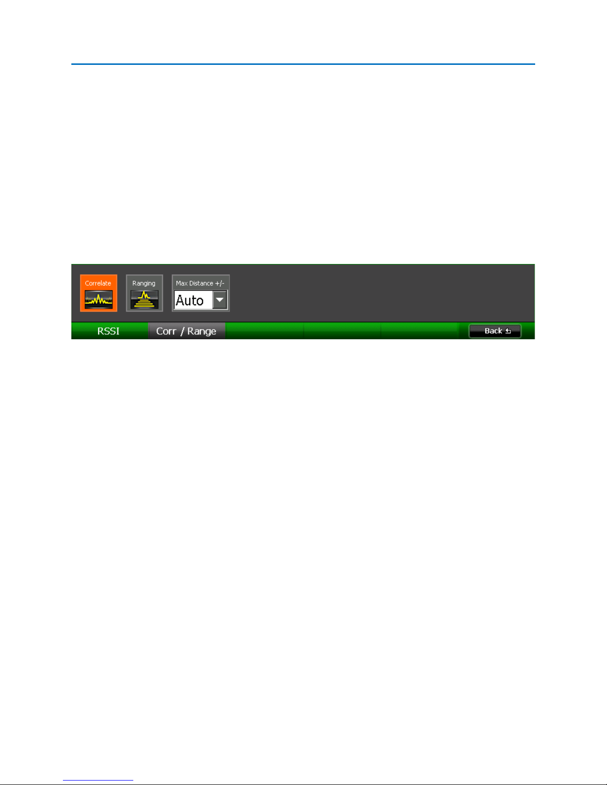
OPERATION
• Threshold – The relative level of the RSSI graph can be adjusted to make it easier to see small
variations in signal strength. Select the Threshold icon from the Locate Sub-Menu and then
adjust the threshold level using the rotary knob. Press OK when you are done.
• Clear RSSI – Select the Clear RSSI icon to erase the currently displayed RSSI graph and begin
collecting RSSI data again.
Correlation
The correlation function allows the OSCOR unit to identify a demodulated analog audio signal as an
eavesdropping device. It compares complex sound patterns in the ambient room noise to the
demodulated audio to determine if they correlate or match.
To use the correlation function:
1. Ensure that the audio from the OSCOR unit is muted. If the demodulated audio is playing from
the OSCOR unit’s speakers it will be picked up by the OSCOR’s microphone, which will always
result in a correlation. If you wish to listen to the demodulated audio signal while using the
correlation feature, use headphones.
2. While demodulating an analog video signal, select Corr / Locate or press F4 from the Analyze
Mode Menu. (Note: From the Demod Submenu, it will be necessary to select Back or press F6
to return to the Analyze Mode Menu.)
3. From the Corr / Locate Submenu, select Corr / Range or press F2.
4. From the Corr / Range Submenu, select the Correlate icon. A new tabbed window, Correlation,
will appear displaying a correlation graph.
Random data throughout the graph indicates that the demodulated audio does not correlate with room
audio.
77
Page 85

OPERATION
An increased level in the center of the graph is an indication that the demodulated signal correlates with
room audio and could be a potential threat. The OSCOR unit will automatically assess the correlation
graph and make a determination regarding whether or not the demodulated audio correlates with the
ambient room noise. The unit’s determination is displayed on the top left hand side of the correlation
graph.
To the right of the correlation graph, the OSCOR unit displays frequency domain graphs of the two audio
signals it is comparing to make its correlation determination. The graph labeled “Room” is the room
78
Page 86

OPERATION
audio as received by the microphone on the OSCOR. The graph labeled “Demod” is the demodulated
audio from the currently tuned signal.
Note: Ideally, for an accurate correlation determination, the most prominent sound source heard by the
OSCOR unit should also be the most prominent sound heard by the bug. It may be advantageous to
have an easily perceptible, non-periodic sound source in the room; music or conversation in an
otherwise silent room should work well. It may also be beneficial to walk around the room with the
OSCOR unit to increase the chances of both the OSCOR and the bug hearing the same ambient
noise. The fan noise from the unit, although it may be almost imperceptible as far as ambient noise is
concerned, will be very significant to the OSCOR’s speakers. This should be taken into account when
checking for correlation.
Warning: If the OSCOR determines that there is no correlation between demodulated audio & ambient
room noise, it does not necessarily mean that the signal is not a threat; it only means that the signal
does not acoustically correlate with the selected form of demodulation. Signals that are digitally
modulated, spread spectrum, frequency hopping, or contain video content will not correlate. To locate
the source of these types of signals, you will need to use other methods, such as RSSI level (see page 76)
or RF mapping, a process taught in REI’s TSCM training classes. Contact REI (sales@reiusa.net
training dates.
) for
Ranging
The ranging function uses a sound source and the speed of sound to calculate the range of a correlated
signal.
For the most accurate ranging information, the OSCOR unit features a white noise generator, which is
used for the sound source. However, it is important to note that this may alert others to your counter
surveillance activities.
Note: If during the correlation phase, headphones were used to listen to demodulated audio, it will be
necessary to unplug the headphones from the OSCOR unit during the ranging phase. The white noise
generated by the OSCOR needs to be picked up by the unit’s internal microphone and by the potential
eavesdropping device. For this to occur there can be no headphones plugged into the headphone jack
on the OSCOR unit, so that the white noise is heard from the OSCOR unit’s built-in speakers.
To use the ranging function:
1. If during the correlation phase described above, a demodulated signal correlates with room
audio, the OSCOR unit is able to determine the distance, or range, from the OSCOR to the
listening device. To determine this distance, select the Ranging icon from the Corr | Range
submenu. Note: The Ranging icon cannot be selected unless the Correlate icon is highlighted.
2. If the audio of the OSCOR unit is currently muted, you will be presented with a dialog box asking
if you wish to unmute for ranging. Select OK or press F5 to unmute the audio and use white
79
Page 87

OPERATION
noise generated by the OSCOR to perform the ranging function. Select Cancel or press F6 if you
have decided not to use the ranging function.
3. By comparing the white noise received by the built-in mic and that received through the
demodulated audio it makes a determination as to how far away the eavesdropping device is.
The distance determined by the unit is displayed at the top left hand side of the correlation
graph in parentheses after the correlation determination.
4. The Max Distance +/- drop down box can be used to zoom in on the correlation graph to see
more detail. To zoom in, select a smaller distance.
5. The OSCOR unit will automatically detect which peak is the generated white noise and display
the distance to the eavesdropping device. A red cursor with an arrow is used to indicate the
peak that the OSCOR unit has detected as the sound source. The white cursor that also appears
on the correlation graph is adjustable and can be used to determine distances for the various
peaks of the correlation graph. Tap the correlation graph with your finger or stylus so that it has
focus and you can use the rotary knob to change the position of the cursor. Each peak on the
correlation graph represents a sound source or reflection that is being detected by both the
OSCOR and the eavesdropping device.
80
Page 88

OPERATION
IF Out Frequency Display
6. While using the ranging function, walk around the room carrying the OSCOR unit. The distance
indicated by the ranging function will get smaller as you near the eavesdropping device. It
should be noted that this particular step could be alerting to a potential eavesdropper.
IF Out
The IF Out port (see page 5) is active anytime that the OSCOR unit is in Analyze Mode. The center
frequency of the IF Out is 75 MHz with a 3 dB bandwidth of 25 MHz. Any signal centered on the
spectrum window will appear at the IF out port, but due to the hardware configuration of the OSCOR it
will not be centered at 75 MHz. To assist with identifying signals on the IF port, the IF Out Frequency of
the current cursor position is displayed in Analyze Mode.
To turn the IF Out display off or on:
1. From the Analyze Mode Menu, select Display or press F2.
2. From the Display Sub-Menu, select the Show IF Out icon to turn the IF Out display on.
Deselect the Show IF Out icon to turn the IF Out display off.
Baseband Out
The Baseband Out port (see page 5) can be used to supply a demodulated baseband signal to external
equipment for further analysis, e.g. running a video signal to external monitors. It is available anytime
the OSCOR unit is demodulating an analog signal using the 12.75 MHz, 6.375 MHz, 800 kHz, or 200 kHz
bandwidth filters.
To activate the Baseband Out Port while demodulating an analog signal:
1. From the Analyze Mode Menu, select Options or press F5.
81
Page 89

OPERATION
2. From the Options Sub-Menu, select the Baseband Out icon to turn the Baseband Out
port on. Deselect the Baseband Out icon to turn the Baseband Out port off.
Note: Whenever the Baseband Out port is on, the video display on the OSCOR unit will lose color. This is
normal and is due to hardware limitations in the unit.
Note: The Baseband Out port has no low pass filter and may contain alias images.
Cursor Lock
For many of the operations in Analyze Mode, you may find it useful to lock the cursor for the main
carrier so that the tuned frequency doesn’t accidentally change during analysis.
To lock the main carrier cursor:
1. From the Analyze Mode Menu, select Options or press F5.
2. From the Options Sub-Menu, select the Lock Cursor icon to lock the cursor for the main
carrier. Deselect the Lock Cursor icon to unlock the cursor.
Receiver Overload – Analyze Mode
Just as with sweep mode, a receiver overload condition in Analyze Mode can cause intermodulation
distortion and false spurs. The overload indicators used in Sweep Mode were described on page 63. For
analyze mode, an overload condition is indicated by the warning text “Input Overload!” in the upper
right hand corner of the spectrum graph.
The “Input Overload!” warning indicates that an overload condition has occurred somewhere within the
displayed spectrum. To fix the overload condition, apply the smallest amount of input attenuation (see
page 27) that is necessary to get rid of the “Input Overload!” warning. Begin by applying 10 dB of
attenuation. If 10 dB of attenuation will not get rid of the “Input Overload!” warning and the false
spurs, then try 20 dB, and then 30 dB.
82
Page 90

OPERATION
In the screenshot above, a very strong signal has caused an overload condition, creating several false
spurs and causing the “Input Overload!” indicator to appear on the spectrum.
Applying just 10dB of input attenuation has eliminated the overload condition. The overload indicator
has disappeared along with all of the false spurs.
83
Page 91
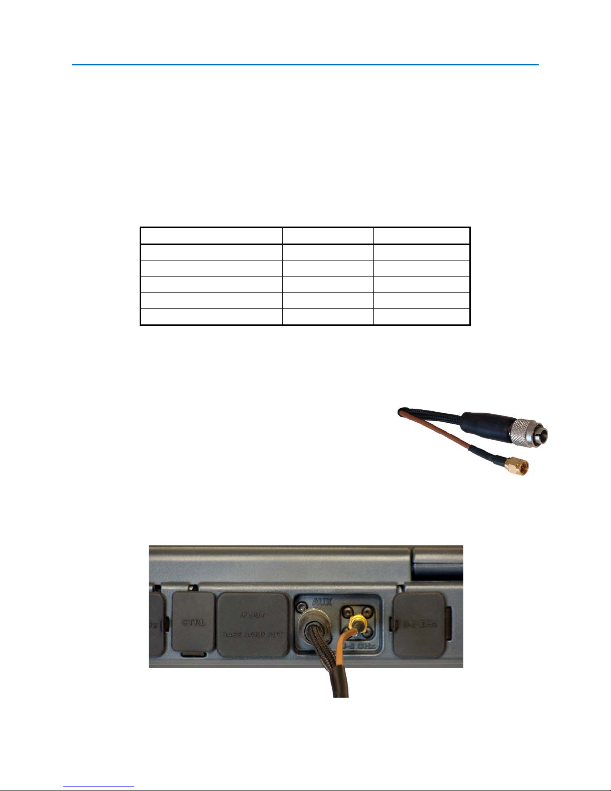
MULTI-PURPOSE PROBE
Sensor/Antenna
Frequency Range
Wavelength Range
Coax (In-Line & Single-Ended)
5 MHz – 2 GHz
Not Applicable
CCP (Carrier Current)
50 kHz – 150 MHz
Not Applicable
VLF (Loop Antenna)
20 kHz – 20 MHz
Not Applicable
IR (Infrared Light)
50kHz – 1.2 GHz
700 – 1100 nm
VL (Visible Light)
50 kHz – 1.2 GHz
450 – 1100 nm
THE MULTI-PURPOSE PROBE (MPP)
The multi-purpose probe, or MPP, is a small portable probe that attaches to the auxiliary port of the
OSCOR unit and extends its functionality with the addition of different sensors/antennas to allow the
capture and analysis of suspicious signals: Coaxial Connectors, Carrier Current Probe (CCP), VLF Antenna
(Loop Antenna), Infrared (IR) sensor, and a Visible Light (VL) sensor.
The table below summarizes the frequency range for each sensor/antenna and the wavelength range for
each of the photo sensors.
Connecting the MPP to the OSCOR Unit
1. Pushing on the edge of the VLF antenna (see page 94), slide it open far enough that you are able
to unwind the MPP cable.
2. The MPP has two connectors on the end of the cable: an 8-pin
circular connector and an SMA connector.
3. Connect the 8-pin circular connector to the AUX jack on the
back of the OSCOR unit.
4. Connect the SMA connector to the 0-8 GHz auxiliary jack to the right of the AUX jack.
84
Page 92

MULTI-PURPOSE PROBE
5. Upon connecting the MPP, if the OSCOR unit is powered on and using the built-in antenna
panel, you will be presented with a dialog box.
6. Select Yes or press F5 to switch the RF input to the MPP. The Aux RF icon in the Setup Menu will
be replaced with an MPP icon. Also, a tabbed panel will be added displaying options for all of
the inputs.
Notes
- If you select No when prompted to switch inputs to the MPP, the OSCOR unit will continue to
use the built-in antenna panel. To switch to the MPP input at a later point, select the MPP icon
from the Setup Sub-Menu.
- Avoid connecting the MPP during start-up of the OSCOR unit; either connect the MPP before the
unit is powered on or wait until the boot sequence is finished.
85
Page 93

MULTI-PURPOSE PROBE
OSCOR Unit Operations with the MPP connected
Most of the OSCOR operations continue to operate with the MPP just as they do with the built-in
antenna panel. The maximum frequency range will automatically be adjusted for whichever MPP input
is selected; however all the other functions will operate the same. You can use the preamp or
attenuators, narrow in on specific frequencies, save a peak trace, look at an average trace, turn on detail
zoom, and generate a signal list. If a signal is detected, you can go to analyze mode and even
demodulate any analog signals that might be present.
Caution: Switching between MPP inputs will clear the peak trace. Be sure to save the peak trace before
switching probes for any data you wish to keep.
Selecting an MPP Input
Only one sensor or antenna on the MPP can be active at any given time. To activate a sensor or
antenna, select it from the list in the MPP tab by tapping it with the stylus.
After selecting an input from the list in the MPP tab, options for that input will be displayed on the right
side of the MPP tab. Options vary according to the selected input.
86
Page 94

MULTI-PURPOSE PROBE
Coax (In-Line)
Two of the MPP functions utilize the coaxial connectors: Coax (In-Line) and Coax (Single-Ended). The
Coax (In-Line) Setting allows you to make in-line measurements using one of the coax ports as an input
and the other as an output. The MPP contains a directional coupler between port A and port B.
Therefore, if a signal is originating from the Port A coax input, then the signal should appear stronger
when the MPP is switched to port A versus port B. This technique can be used to determine if a signal is
originating from either the port A or port B side of the coax without having to physically switch the
cables on the inputs.
To use the Coax (In-Line) Input:
1. If making an in-line measurement on the coax cable from a wall outlet to a television, disconnect
the coax cable from the back of the television. Connect this cable to Coax Port A on the MPP.
2. Take the extra length of coax cable included with your OSCOR unit and connect Coax Port B on
the MPP to the television. Signal will be restored to the television.
3. On the OSCOR, make sure that the “Coax (In-Line)” input is selected on the MPP tab. On the
right side of the tab, the options for the selected input will appear.
4. On the options panel, select Port A as the input port. Observe any signals present on Port A.
87
Page 95

MULTI-PURPOSE PROBE
5. It is advisable to save this trace for later comparison. Select Traces from the Main Menu or
press F2. From the Traces Sub-Menu, select Peak / Avg or press F2. Select the Save Peak icon
from the Peak/Avg Sub-Menu.
6. Clear the peak trace before moving on to the next step. While still in the Peak/Avg Sub-Menu,
select the Clear Peak icon.
7. On the options panel of the MPP tab, select Port B as the input port. Observe any signals
present on Port B. Remember, because the two inputs are coupled, any signal seen at one input
will be present at the other also, but at an attenuated level, so comparing traces from each input
will give you a pretty good idea which side the suspicious signal is originating from.
88
Page 96
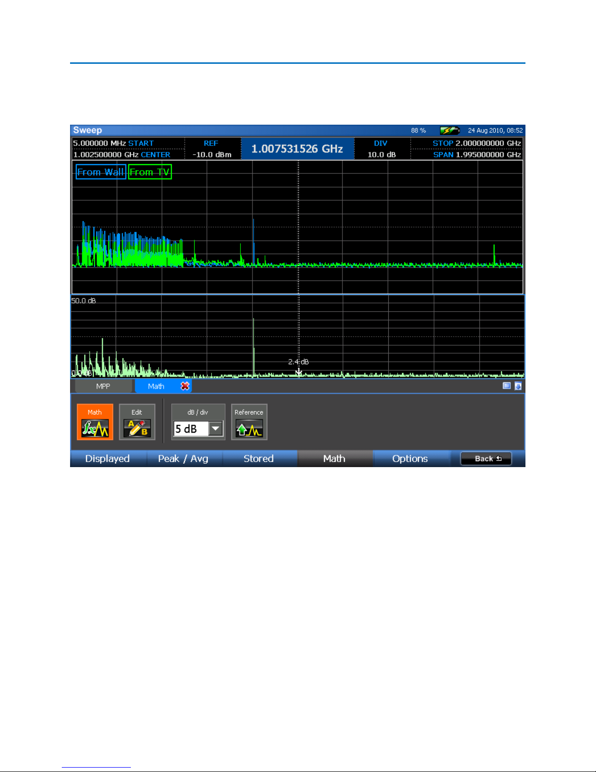
MULTI-PURPOSE PROBE
8. Repeat step 5 to save a Peak Trace from Port B. The two saved peaks can now be compared to
identify possible suspect signals. A math trace can also be performed on these two peaks (see
page 42)
Notes:
- Always verify the directionality of any suspicious signal by connecting each side up individually.
Coax (Single-Ended)
The coax connectors on the MPP can also be used for single-ended measurements.
89
Page 97
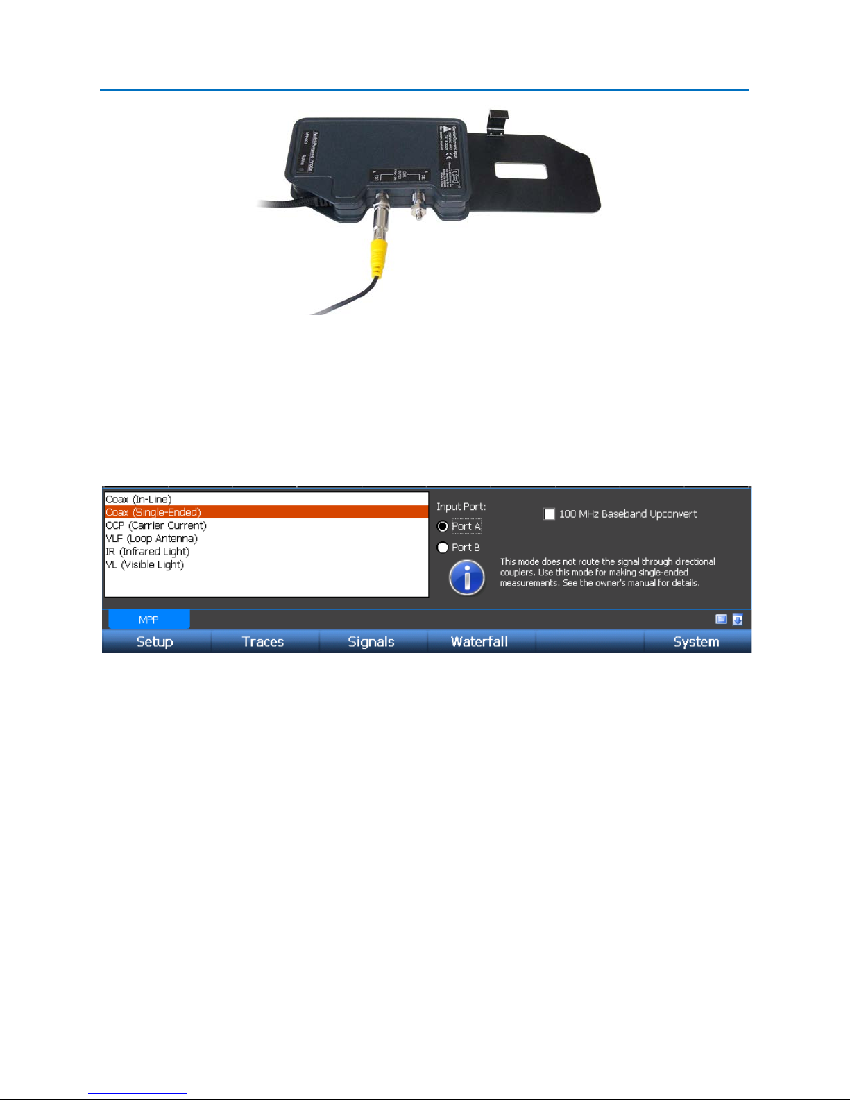
MULTI-PURPOSE PROBE
To measure signals using the Coax (Single-Ended) inputs:
1. Connect the signal up to either coax port A or port B. Be sure and connect the 75 ohm
terminator included with the OSCOR to the remaining port.
2. On the OSCOR unit, make sure that the “Coax (Single-Ended)” input is selected. The options for
the Coax (Cable TV) input will appear on the right side of the MPP tab. From the options panel,
select the port that the cable is connected to.
Notes
- The coax connectors on the MPP can be used as general purpose inputs. Any type of signal in
the 5 MHz to 2 GHz range may be connected to these inputs for measurement. Adapters may
be necessary to connect to the F-type connectors. Adapters are not included as part of the
OSCOR Unit.
- The coax connectors are coupled even when in Coax (Single-Ended) mode. Because of this, any
signal connected to one of the ports will be seen at the other port. As such, Coax (Single-Ended)
mode will act very similar to Coax (In-Line) mode, however, the directionality component is not
as strong but there is less overall attenuation. Therefore, it is best to use Coax (In-Line) mode to
determine the directionality of an in-line measurement without having to physically switch the
inputs and to use Coax (Single-Ended) mode when making single-ended measurements.
90
Page 98

MULTI-PURPOSE PROBE
- Because the two coaxial connectors are coupled and because any signal connected to one of the
ports will be seen at the other port, it is not advisable to connect two different signals to ports A
and B at the same time.
- The 100 MHz Baseband Upconvert option mixes the signal with a 100 MHz signal for analyzing
baseband (see page 97).
CCP (Carrier Current Probe)
The CCP (Carrier Current) input can be used to test for carrier current signals on any pair of conductors
less than 250 volts. Before testing an unidentified pair of power conductors, a voltmeter should be used
to measure the voltage across the conductors. If this voltage exceeds 250 volts, do not test with the
MPP.
To measure carrier current with the MPP:
1. Ensure that the battery level of the OSCOR
is enough to power the unit.
2. Remove the power cord from the AC adapter used to
power the OSCOR unit.
3. Plug the power cord into the Carrier Current Input on the MPP.
4. Plug the other end of the power cord into the outlet you wish to check.
5. On the OSCOR unit, make sure that the “CCP (Carrier Current)” input is selected. The options for
CCP testing will appear on the right side of the MPP tab.
6. Measurements can be made with three different pair configurations: Hot/Neutral,
Neutral/Ground, and Hot/Ground.
7. To automatically switch between all three different pair configurations, select “Enable Auto
Sequencing.” The MPP will automatically rotate through the pair selections after a few seconds
each.
91
Page 99

MULTI-PURPOSE PROBE
Notes
- Noise from the AC power supply may interfere with carrier current measurements. Be sure that
the AC power supply for the OSCOR unit is not plugged into the electrical circuit that you are
testing for carrier currents.
- Be aware that any switching power supply connected to the electrical circuit that you are
measuring may affect carrier current measurements
92
Page 100
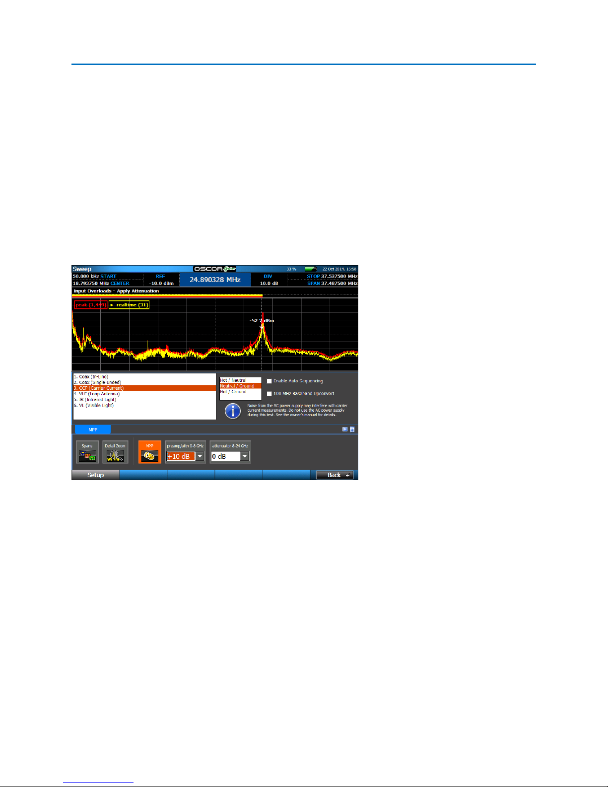
MULTI-PURPOSE PROBE
- The 100 MHz Baseband Upconvert option mixes the signal with a 100 MHz signal for analyzing
baseband (see page 97).
- A break-out cable with alligator clips is included with the OSCOR unit for use with the carrier
current input. This cable should not be used with power circuits.
Receiver Overload - MPP Carrier Current Probe
When using the MPP to test for carrier current on the ground line, there typically is a lot of RF emissions
at the low end of the spectrum. This RF energy can cause the OSCOR to display the Input Overload
warning. This can occur especially if the preamp is turned ON. The tuner overload condition can cause
false spurs to occur, specifically around 12 and 24 MHz.
To clear the error, apply just enough attenuation until the input overload warning is no longer displayed.
If the signals are still present after the attenuation is applied, they should be considered actual threats.
VLF (Loop Antenna)
The VLF (Very Low Frequency) input uses a loop antenna for analyzing the RF spectrum at low
frequencies.
93
 Loading...