

Page 1
AM/FM/CD/MP3 Receiver with USB/SD & A u x iliary Input
3 Built-in Microphone inputs for P A Announcements
Installation/Operation Manual
50W x 4 CD-2000
Page 2
2
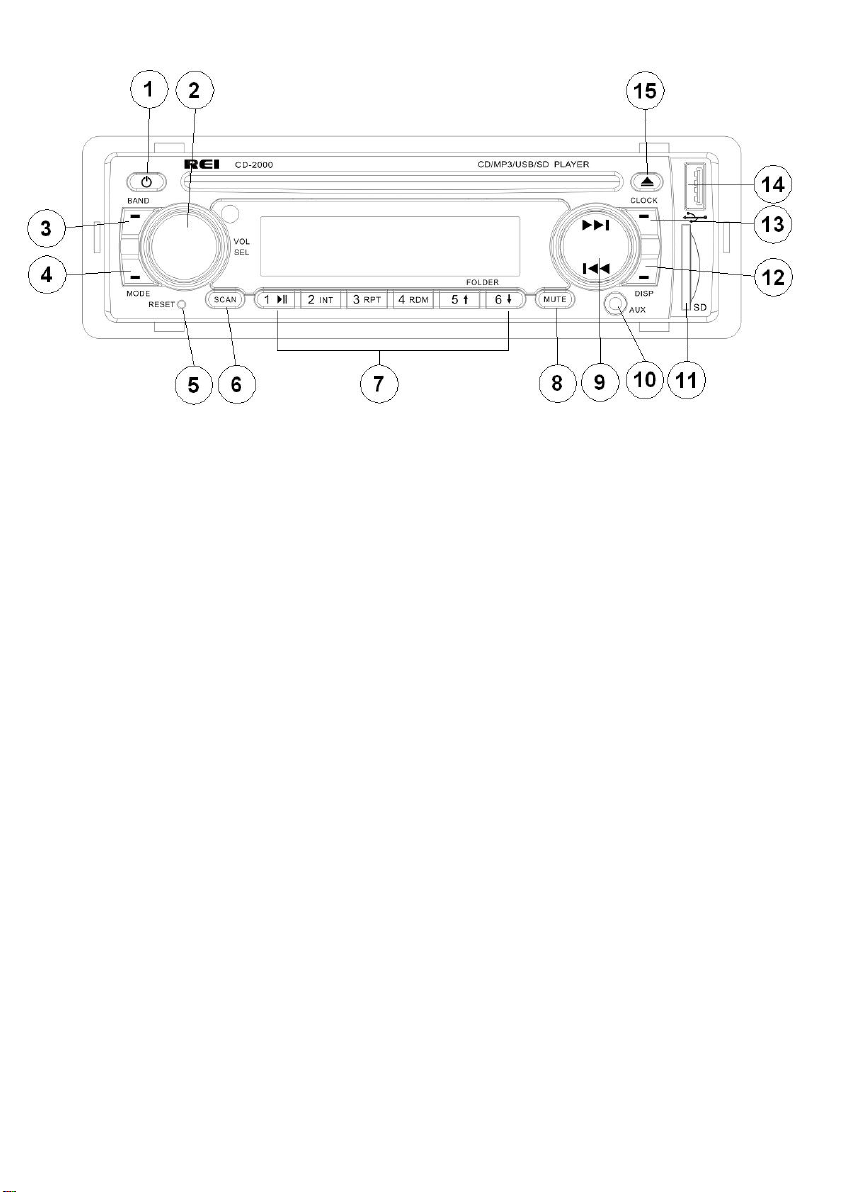
CONTROLS AND INDICATORS
(1) Power Button
(2) Volume/Select Knob
(3) Band Button
(4) Mode Button
(5) Reset Button
(6) Scan Button
(7) Preset Memory Buttons/r Playback Options
(8) Mute Button
(9) Radio Station Tune/Seek, Track Control Buttons
(10) Front Auxiliary Input Jack
( 1 1 ) SD Card Input slot
(12) Display Button
(13) Clock Button
(14) USB Input Slot
(15) Eject Button
Page 3

3
Thank you for purchasing the CD-2000 AM/FM/CD/MP3/USB/SD Receiver from REI.
This product is designed and tested to withstand temperature and vibration extremes.
Please read the owner’s manual carefully before attempting to install.
If you have an installation question or need installation assistance, please call the:
SERVICE HOT LINE
1-877-726-4617 Toll Free USA & CANADA
1-402-339-2200
AM/FM Stereo Receiver
30s Anti-skip CD
Front-panel USB type-A input
Front-panel SD/SDHC CARD input
Plays MP3/WMA file formats
Independent front panel 3.5mm and rear RCA auxiliary input jacks
Non-Volatile memory back-up
50W x 4 Output power
USA/EURO Radio Frequency modes
Amber LED backlighting
3 Microphone input jacks for PA announcements
IF ADDITIONAL INSTALLATION COMPONENTS ARE NECESSARY, CONTACT YOUR REI
SALES REP FOR:
** OEM /FACTORY WIRING HARNESS ADAPTERS
** ANTENNAS & ANTENNA ADAPTERS
** SPEAKERS & GRILLS
Radio Engineering Industries, Inc. Radio Engineering Industries, Inc.
6534 “L” Street
Omaha, Nebraska 68117
www.radioeng.com
Page 4

4
OP E R A T I O N
1) P o w e r Button
Press the Power Button to turn ON or OFF the unit. A red light means the unit is in
standby, a Blue light means the radio is on.
2) Volume/Select Knob
Rotate the knob left or right to change the volume level.
Press the knob to select one of the following functions:
VOL---BASS---TREB---BAL---F A D
Rotate the knob to adjust the desired setting.
3) Band Button
Press this button to change radio bands as follows:
FM1—FM2—FM3—AM1—AM2
Press this button to confirm changes in the S E T U P m e n u
4) Mode Button
Press this button to select source mode (RADIO/DISC/USB/CARD/AUX1/AUX2)
*USB and SD card must be inserted to activate these modes
5) Reset Button
If there is a malfunction of the unit, pressing the RESET button will clear the system
6) Scan Button
Press and hold this button for 2 seconds to auto program available stations into all the
preset memory buttons. This function will erase previous memorized stations and store
the newly searched stations. Once completed, the radio will scan for 5 seconds through
each of the preset stations of either the AM or FM band.
Press this button to automatically preview all radio stations in that band for 5 seconds
7) Preset Memory/Recall Buttons
Press these buttons momentarily to select the preset stations.
Press and holding a button will preset the current station to the button being pressed.
During MP3 playback, use these buttons to scroll through available folders.
Press this button to PAUSE/PLAY the media (CD/SD/USB)
Press and hold this button to select INTRO ON/OFF on CD playback
Press and hold this button to change REPEAT from Track, Folder, All
Press and hold this button to turn RANDOM ON/OFF
8) Mute Button
Press this button to mute the source audio.
Page 5

5
9) TUNE / SEEK /TRACK Buttons
Under Radio mode, press the desired button to manually tune a station moving upward
or downward. Press and hold button momentarily and the radio will automatically seek
or down to the next available radio station. Press and hold button for 2 seconds and the
radio continuously tunes up or down until the button is released.
When playing digital media, use these buttons to track UP/DOWN to the desired
chapter to playback.
10) Auxiliary Input Jacks
The unit is equipped with a front panel 3.5mm auxiliary input so you can connect your
external portable audio player or portable satellite radio receiver. Press Mode to
display AUX 1 for operation. The radio is also equipped with a second Rear RCA
AUX 2 input. Press mode to display AUX 2 for operation.
*It may be necessary to adjust the volume level of your portable devise to achieve an
optimal volume level.
11) SD Card Input
Insert the SD card and the radio will automatically switch to the CARD input and
begin playback.
12) Display Button
Press this button to change display between available source information.
13) Clock Button
Press this button to change display between clock and source information.
Setting the Time:
Press this button momentarily to display the time. Next, press and hold this button
until the hour display begins to flash. Rotate Volume/Select Knob to adjust the hour.
Press the CLK button again, and the minute display will flash. Rotate Volume/Select
Knob to adjust the minute. Press Volume/Select to save the desired time .
14) USB Input
Insert a USB drive and the radio will automatically switch to USB input and begin
playback.
**Note: The unit's USB port does not support the Apple iPod or iPhone.
15) Eject Button
Press this button to eject CD disc.
Page 6

6
PA OPERATION
The CD-2000 has three PA Microphone inputs, 2 Dynamic & 1 Carbon microphone
input. All microphones have priority over all other audio modes and MUTE the
source audio being played when keyed. When the PA is triggered, the front display
will show MIC 1, MIC 2 or MIC, until the trigger is un-keyed. Once released, it will
return to the previous source mode at the previous volume level.
The Dynamic MIC 1 input is the Primary, and the other input MIC 2 is the Secondary.
When the two are keyed simultaneously, the MIC 1 microphone will always have
priority over the MIC 2.
All PA inputs operate regardless of radio p o w e r status, as long as both ACC and
Battery power is applied to the radio. The volume levels of MIC 1 & MIC 2 can be
independently adjusted from the radio’s main Volume/Select knob on the front of the
radio. Once released, their final volume levels are stored into memory as default for
the next time they are keyed. The volume levels of MIC 1 & MIC 2 can only be
adjusted when they are keyed. The volume of the Carbon microphone MIC is only
adjustable on the microphone itself and therefore its level is not saved. A rear view
of the radio’s PA pin connections are shown below:
Page 7

7
RADIO CONNECTIONS
Follow this easy wiring diagram when installing. Be sure to disconnect the battery
negative terminal before beginning.
Page 8

8
REQUIRED RADIO DIMENSIONS
Verify the radio will fit by following the suggested dimensions below.
RADIO INSTALLATION
1. Verify lock Clips on the DIN collar are pressed inward. Place the collar into
the dash opening. Bend the tabs outward as shown on the drawing below to secure
into place in the Dash Opening.
2. Route all cable through the DIN collar and make all the necessary rear
connections with the radio. Verify clearance; then gently insert the radio into the DIN
Collar until both sides are locked. Secure rear mounting stud for additional support.
Page 9

9
RADIO REMOVAL
3. To remove the radio, disconnect the rear support stud if installed. Remove the
front Trim Ring and insert the two release keys on either side of the radio then pull the
radio out.
TROUBLESHOOTING
Pro b l e m
Cause
M e a s ure
Power light does n ot turn on
No power to yellow wire; no power
to red wire; blown fuse
Check for ACC/BATTERY
voltage with Multi-meter, check
fuse; press RESET button.
Spea ker s have no sound
Speakers not connected; speakers
connected with bad splices;
Speakers shorted to ground; total
speakers load not within 4-8Ω/ch
Connect speakers to harness;
check all spliced wires; verify
speakers not shorted to chassis;
verify total speaker impedance.
Public Address is not be heard
over sp eak er s
Microphone volume level is “0”;
microphone is plugged into the
wrong input; wrong microphone
type is used
Turn the volume up when the
LCD display’s MIC 1 or MIC 2;
Check that the correct
microphone type is connected
Digita l med ia won’t play or
says “Unsupported Video”
Media is an unsupported file type.
Encode media with a supported
file type; make sure disc has
been finalized; use different
software
LCD Display says MIC /MIC 1/
or MIC 2 and front controls a re
lock ed
PA system is triggered
Remove microphone connections
and verify correct pinning;
replace microphone
Page 10

10
SPECIFICATIONS:
General Specifications
Operating Voltage (10.0 –15.6V allowable)
Maximum Current Consumption 10A
POWER OUTPUT
Continuous Output (4Ω, 20 to 20,000 Hz at 1% THD) 4 x 22 Watts
Maximum Power Output 4 x 50 Watts
Speaker Impedance 4-8 Ohms
FM STEREO RADIO
Frequency range USA 87.5MHZ – 107.9MHZ (0.2 MHz step)
EURO 87.50MHZ –108.00MHz (0.05 MHz step)
Usable Sensitivity 10.2 dBf. (0.9 uV, 75Ω)
50db Quieting Sensitivity 15.2 dBf. (1.6 uV, 75Ω)
Frequency Response 30Hz – 15kHz (+/- 3dB)
Alternate Channel Selectivity 75dB
Stereo Separation 40dB (1kHz)
Image Rejection Ration 75dB
IF rejection ratio 100dB
Signal to Noise ratio 70dB
AM RADIO
Frequency range U S A 530kHz – 1710kHz (10 kHz step)
EURO 522kHz – 1620kHz (9 kHz step)
Usable Sensitivity 27 dB/uV (25uV, S/N 20dB)
CD/PLAYER
Signal/Noise Ratio (1kHz) 75dB
Frequency Response (+/- 1dB) 5 – 20,000Hz
Total Harmonic Distortion (1kHz) less than 0.20% (1Khz)
Number of Channels 2 (stereo)
MP3 decoding format MPEG-1 & 2 Audio layer 3
WMA decoding format Ver. 7, 7.1,8,9,10,11 (2ch audio)
(Windows Media Player)
Usable Discs: SVCD, CD-R/RW, CD-Audio,
CD-MP3, CD-WMA
Page 11

1 1
USB INTERFACE
USB S t a n d a r d USB1.1/2.0 (Full Speed)
Maximum Supply Current 500mA
File System Fat16/32
Decoding Forma t same as CD
SD CARD INTERFACE
Frequency Response (+/- 1dB) 10 – 20,000Hz
Dynamic Range 80dB (1kHz)
Harmonic Distortion 0.01%
Decoding F o r mat same as CD
AUDIO PRE-A M P SPECIFICATIONS
Max Output level 5V
Output Impedance 600Ω
Subwoofer output Not adjustable
AUXILIARY INPUT SPECIFICATION
Frequency Response (+/- 1db) 20HZ – 20Khz
Input V oltage Maximum Voltage 1200mV
Input impedance 100KΩ
Radio Engineering Industries, Inc. Radio Engineering Industries, Inc.
6534 “L” Street
Omaha, Nebraska 68117
Phone: 402-339-2200 Toll-Free 1-800-228-9275
www.radioeng.com
Rev 0 12-9-10
 Loading...