

REHM INVERTIG.PRO digital 450 DC, INVERTIG.PRO digital 240 DC, INVERTIG.PRO digital 350 DC, INVERTIG.PRO digital 280 DC, INVERTIG.PRO digital 240 AC/DC Operating Instructions Manual
...
GB
OPERATING INSTRUCTIONS
TIG inert gas welding units
INVERTIG.PRO digital 240 – 450 DC / AC/DC

Operating instructions
2
Operating instructions
TIG inert gas welding units
INVERTIG.PRO digital 240 DC, 240 AC/DC
INVERTIG.PRO digital 280 DC, 280 AC/DC
INVERTIG.PRO digital 350 DC, 350 AC/DC
INVERTIG.PRO digital 450 DC, 450 AC/DC
Rehm GmbH u. Co. KG
Ottostr. 2
73066 Uhingen, Germany
Telephone: 07161/3007-0
Fax: 07161/3007-20
Email: rehm@rehm-online.de
Internet: http://www.rehm-online.de
Document number: 730 0143
Release date: 25.06.2015
Rehm GmbH u. Co. KG, Uhingen, Germany 2011
The contents of this description are the sole property of Rehm GmbH u. Co. KG
The disclosure or reproduction of this document, the sale and communication of
its content are prohibited unless expressly permitted.
Actions to the contrary will be subject to compensation. All rights are reserved in
the case of patent, utility patent or registered design.
Manufacture using these documents is not permitted.
Subject to change.
Description
Type
Manufacturer

Index
3
Index
Product identification 2
1. Introduction 6
1.1 Preface 6
1.2 General description 7
1.2.1 Principle of the TIG inert gas welding procedure 8
1.2.2 Areas of application of the TIG welding units 8
1.2.3 Functional principle of the TIG welding units 8
1.2.4 Correct use 8
1.3 Symbols used 9
2. Safety notes 10
2.1 Safety symbols used in these operating instructions 10
2.2 Warning symbols on the unit 10
2.3 Notes and requirements 11
3. Functional description 13
3.1 Description of controls 13
3.1.1 Application buttons 14
3.1.2 Multifunction buttons 14
3.1.3 Push and rotate knob (R Pilot) 14
3.1.4 High-resolution TFT display 15
3.2 Switching on 15
3.3 Special features of the control panel 15
3.4 Classic application 15
3.4.1 Multifunction buttons of the Classic application 16
3.4.2 Basic settings of the multifunction buttons 17
3.5 Welding procedure multifunction button 17
3.5.1 TIG welding 17
3.5.2 TIG points 17
3.5.2.1 TIG spot welding, 2-step 18
3.5.2.2 TIG spot welding, 4-step 19
3.5.3 WIG Interval 20
3.5.3.1 TIG interval, 2-step 20
3.5.4 Electrode welding 21
3.6 The welding parameters 21
3.6.1 Basic setting of welding parameters. 21
3.6.2 Gas preflow time 22
3.6.3 Ignition energy 22
3.6.4 Start current 23
3.6.5 Upslope time 23
3.6.6 Welding current I1 23
3.6.7 Welding current I2 24
3.6.8 Downslope time 24
3.6.9 End crater current 25
3.6.10 Gas post-flow time 25
3.7 Polarity multifunction button 26
3.7.1 AC current (AC) 26
3.7.1.1 AC balance (%) 27
3.7.1.2 AC frequency Hz 28
3.7.1.3 AC curve shape selection facility 29
3.7.2 DC current positive terminal 30
3.7.3 DC current negative terminal 30
3.7.4 Dual Wave 30
3.8 Multifunction button 2- / 4-step and high frequency 31
3.8.1 2-step function 32
3.8.2 4-step function 32

Index
4
3.8.3 Welding with high frequency (HF) 33
3.8.4 Welding with Lift-Arc 34
3.9 Pulsing multifunction button 34
3.9.1 I1 pulsing time t1 34
3.9.2 I2 pulse time t2 35
3.10 Electrode welding parameters 35
3.10.1 Welding current I1 during electrode welding 35
3.10.2 Arc Force 36
3.10.3 Hot Start 36
3.10.4 Anti-Stick Function 36
3.11 Quick setting P1 and P2 (Quick Choice buttons) 36
3.12 Programs application (Progr.) 36
3.12.1 Managing folders 38
3.12.2 Main management settings 39
3.12.2.1 Management: Name / Text Entry 39
3.12.2.2 Management: Rename 40
3.12.2.3 Management: Move 40
3.12.2.4 Management: copy 41
3.12.2.5 Management: Delete 42
3.12.3 Loading programs 42
3.12.4 Saving programs 43
3.13 Assist Application 45
3.13.1 Setting the welding task 46
3.13.2 Welding tip 47
3.13.3 Library 48
3.14 System application button 49
3.14.1 System overview 49
3.14.2 Basic selection of machine settings 50
3.14.3 Explanation of system settings 50
3.14.4 Gas test 54
3.14.5 Access authorisation 54
3.14.6 Diagnosis 56
4. Accessories 57
4.1 Overview 57
4.2 Foot remote control P1 iSystem 59
4.3 REHM TIG torch 59
4.4 REHM water-cooling units TIG - COOL CART and TIG - COOL 59
4.5 Handheld remote control P2 12-pin (analog) 59
4.6 Automation INVERTIG.PRO digital 60
4.6.1 Interface INVERTIG.PRO digital standard 60
5. Putting into operation 61
5.1 Safety notes 61
5.2 Working under increased electrical danger 61
5.3 Setting up the welding unit 61
5.4 Connecting the welding unit 62
5.5 Cooling the welding unit 62
5.6 Guidelines for working with welding power sources 62
5.7 Connecting welding cables or torches 62
5.8 Connecting external components 62
6. Operation 64
6.1 Safety notes 64
6.2 Electrical risks 64
6.3 Personal safety tips 64
6.4 Fire prevention 65
6.5 Ventilation 65
6.6 Checks before starting 65
6.7 Connecting the earth cable 65

Index
5
6.8 Practical notes 66
7. Faults 69
7.1 Safety notes 69
7.2 Table of faults 69
7.3 Error messages 72
8. Maintenance work 73
8.1 Safety notes 73
8.2 Maintenance table 73
8.3 Cleaning the inside of the unit 74
8.4 Correct disposal 74
9. Circuit diagrams 75
10. Components of the INVERTIG.PRO digital units 79
10.1 List of components with REHM part numbers 79
11. Technical data 83
12. INDEX 84

Introduction
6
1. Introduction
1.1 Preface
Dear Customer,
You have purchased a REHM inert gas welding unit, a branded German
product. We would like to take this opportunity to thank you for putting
your trust in our quality products.
Only the highest quality components are used in the development and
manufacturing of INVERTIG.PRO digital welding units. In order to
guarantee high durability, even under the toughest of conditions, all
REHM welding units contain components that live up to strict REHM
quality requirements. The INVERTIG.PRO digital welding unit has been
designed and built in accordance with established safety requirements.
All of the relevant legal requirements have been taken into account and
are supported by the conformity declaration and the CE mark.
REHM welding units are produced in Germany and carry the "Made in
Germany" quality mark.
As REHM is constantly developing its products in line with technical
progress, we reserve the right to adapt and modify this welding unit at any
time, in order to meet the latest technical requirements.

Introduction
7
1.2 General description
Figure 1: INVERTIG.PRO digital

Introduction
8
1.2.1 Principle of the TIG inert gas welding procedure
When TIG welding, the arc burns freely between a tungsten electrode and the
work piece. The shielding gas used is an inert gas like Argon, Helium or a mix of
these.
One pole of the energy source is at the tungsten electrode, the other on the work
piece. The electrode is the conductor and the arc carrier (permanent electrode).
The additional material is introduced in stick format by hand, or in wire format
using a separate cold wire feed unit. The tungsten electrode and the pool crater
as well as the liquid melting end of the additional materials are all protected from
the oxygen in the air by the inert gas employed which is released from the
nozzles arranged concentrically around the electrode.
1.2.2 Areas of application of the TIG welding units
INVERTIG.PRO digital DC welding units are direct current power sources. They
are suitable for welding all alloyed and non-alloyed steels, stainless steels and
non-ferrous metals.
INVERTIG.PRO digital AC/DC welding units are both direct and alternating
current sources. They can be used to process all alloyed and non-alloyed steels,
stainless steels, non-ferrous metals, aluminium and aluminium alloys.
1.2.3 Functional principle of the TIG welding units
Our TIG INVERTIG.PRO digital welding units are primary-clocked power sources
in which the welding current is switched by one of the most modern highperformance transistor switches. The On/Off switch relationship of the highperformance transistor switch regulates the set welding current. In conjunction
with the high switching frequency of 100 kHz this generates an extreme stable
and quiet arc. A precise processor controller guarantees constant welding current
even when the distance between the torch and the work piece changes or the
power supply fluctuates. The INVERTIG.PRO digital units have the frequency
automation developed by REHM which ensures for optimum adaptation of the
welding current frequency of the welding current when using alternating current.
With the new REHM AC-Matic, the AC curve shape is automatically adapted to
the current strength. A sine wave curve shape is automatically selected for low
currents, and the square wave curve shape is automatically used for higher
currents
The use of the most modern transistor switching technology means that these
power sources are extremely effective.
1.2.4 Correct use
REHM welding units are designed to weld various metals such as non-alloyed
and alloyed steel, stainless steel and aluminium. You should also pay attention to
the special regulations pertaining to your area of application.
REHM welding units are designed for use with hand-controlled and machinecontrolled operations.
REHM welding units are, unless explicitly permitted in writing by REHM; only for
sale to commercial and industrial users and only for use by such. They may only
be operated by persons trained in the use and maintenance of welding units.
Welding current sources may not be set up in areas with increased electrical risk.
These operating instructions contain rules and guidelines for the correct use of
your unit. Only when these are adhered to can it be described as correct use.

Introduction
9
Risks and damaged caused as a result of a different type of use is the
responsibility of the operator. In the event of special requirements, it may be
necessary for additional special conditions to also be taken into account.
If anything is unclear, consult your safety officer or contact REHM's customer
service department.
You should also pay attention to the special notes regarding correct use set out
in the suppliers documentations.
National regulations regarding the operation of the unit are valid with no
restrictions .
Welding current sources may not be used to defrost tubes.
Correct use also covers the observation of the correct measures with regard to
mounting, removal and remounting, taking into service, operation and
maintenance as well as disposal. Please pay special attention to the
specifications in Chapter 2 Safety notes and Chapter 8.4 Correct disposal.
The unit may only be operated under the conditions set out above. Any other use
is not correct. The consequences are the responsibility of the operator.
1.3 Symbols used
Lists with bullets: General lists
Lists with a square: Work or operational steps that must be carried out in the
sequence listed.
Chapter 2.2, Warning symbols on the unit
Cross-references: In this case, to Chapter 2.2 Warning symbols on the unit
Bold is used for emphasis
Note!
... Refers to tips and other useful information.
The safety symbols used in this manual: Chapter 2.1
Typographic
symbols
Safety symbols
Safety notes
10
2. Safety notes
2.1 Safety symbols used in these operating
instructions
Warning notes and
symbols
This or a symbol more specific to the danger can be found with all safety
notes in these operating instructions which carry a risk to life and limb.
One of the following signalling words (Danger! Warning! Caution!) indicate
the degree of danger:
Danger! ... indicates immediate threat of danger.
If this is not avoided it may lead to death or serious injury.
Warning! ... indicates a potentially dangerous situation.
If this is not avoided it may lead to death or serious injury.
Caution! ... indicates a situation in which damage may occur.
If this is not avoided it may lead to slight or minor injuries and damage to
property.
Important!
Indicates a potentially damaging situation. If this is not avoided it may lead
to damage to the product or to something in the vicinity.
Materials that may be hazardous to health or environment. Materials that
must be treated/disposed of in accordance with the law.
2.2 Warning symbols on the unit
indicate dangers and sources of danger on the unit.
Danger!
Dangerous electrical voltage!
Ignoring may lead to death or injury,

Safety notes
11
2.3 Notes and requirements
The unit has been developed and constructed in accordance with recognised
technical knowledge.
However, using the unit may hold dangers for the life and limb of the user or third
parties or influence the unit or cause damage to other property.
None of the safety measures may be removed or put out of action, as this causes
risks and correct use of the unit cannot be guaranteed. Removing the safety
features during set up, repairs and maintenance is described specially. As soon
as this work is completed, the safety features must be replaced.
When using additional products (for example, solution for cleaning) the operator
of the unit is to ensure that the unit is safe for the product to be used.
All safety and danger notes as well as the type panel on the unit are to be
maintained, kept in a readable state and observed.
Safety notes serve to protect when working and to prevent accidents . They
must be observed.
The safety notes listed in this chapter must be observed along with the special
notes made in running text.
In addition to the instructions in these operating instructions, general safety and
accident prevention regulations (in Germany including UVV BGV A3, TRBS 2131
and BGR 500 Chapter 2.26 (formerly VGB15): "Welding, cutting and associated
processes" and in particular the references to arc welding and cutting and the
appropriate national regulations) must be observed.
Please also note the safety notices in the workplace of the operator.
REHM welding units are, unless explicitly permitted in writing by REHM; only for
sale to commercial and industrial users and only for use by such.
The INVERTIG.PRO digital inert gas welding units are designed in accordance
with EN 60974-1 Arc welding equipment - Welding power sources for
overvoltage category III and pollution level 3 and with EN 60974-10 Arc welding
equipment - Electromagnetic compatibility for Group 2 Class A, and are suitable
for use in all areas, except residential, which are directly connected to a public
low voltage power supply. Due to the cable-related and radiated interferences it
may be difficult to guarantee the electromagnetic compatibility in these areas. For
this purpose, the observation of suitable measures to fulfil the requirements (filter
for network connection, shielding using, for example, screened lines, shortest
possible welding lines, grounding the work piece, equipotential bonding) as well
as the evaluation of the environment (for example, computers, control units, radio
and television masts, neighbouring persons, for example, those using a
pacemaker) should all be carried out. The responsibility for interferences lies with
the operator. See DIN EN60974-10:2008-09, Appendix A for more notes and
recommendations.
High performance units may affect the main power supply thanks to their high
power consumption. For certain units types, there may be connection restrictions,
requirements regarding the maximum permitted net impedance or requirements
regarding the minimum required available power at the point of connection to the
main power supply (see technical data) In these cases, the user of such a unit
must ensure, if necessary by consulting the power suppliers, whether the unit
may be connected.
INVERTIG.PRO digital TIG gas-shielded welding units should only be used
for the specified uses
in a safety-related correct condition
Dangers of nonobservation
Safety instructions
Areas of use
Requirements
made of the main
power supply
Safety notes
12
REHM welding units may only be operated and maintained by persons who have
been educated and trained to operate and maintain welding units. Only qualified,
authorised and trained personnel may work on and with the units.
These operating instructions contain important notes regarding how to operate
this unit safely, correctly and economically. A copy of the operating instructions
should always be kept on site in a suitable location. Please make sure that you
read the information summarised in this operating manual before using the
equipment. It contains important notes regarding use of the device which enables
you to fully use the technical advantages of this REHM devices. In addition, you
will also find information regarding maintenance and upkeep of the units as well
as the operational and functional safety.
These operating instructions do not replace the instructions by REHM's service
personnel.
The documentation for any additional options must also be taken into
consideration.
Changes to the unit or the addition or installation of additional elements is not
permitted. This would expire all guarantee and liability claims.
All third-party changes or deactivation of safety features renders all guarantee
claims invalid.
Qualifications of
the operating
personnel
Purpose of the
document
Changes to the unit
Functional description
13
3. Functional description
3.1 Description of controls
7301671d
INVERTIG.PRO digital
Classic Progr.
System Assist
P2
P1
12
1
2
3
4
56789
10
11
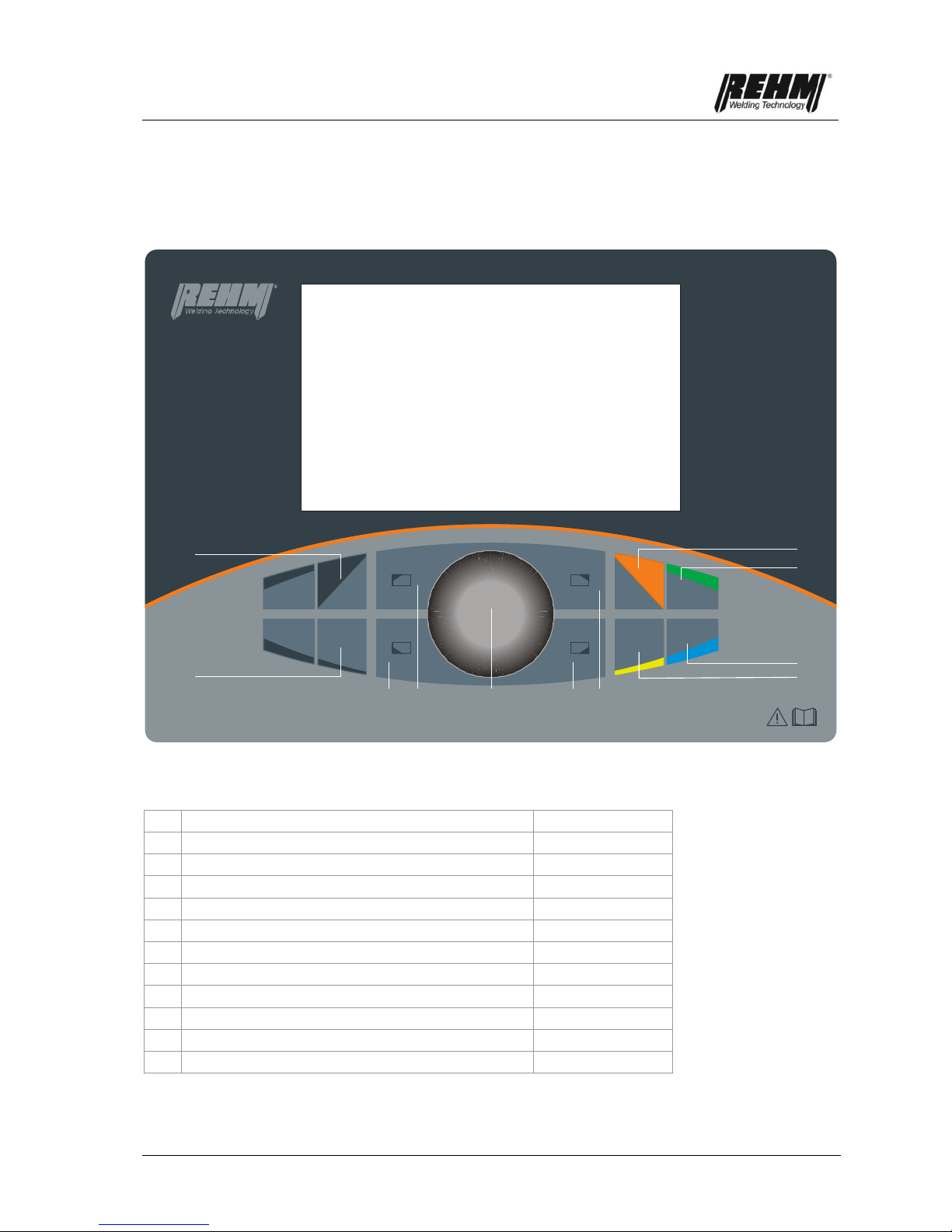
Figure 2: INVERTIG.PRO digital control panel
1
Classic application button
Page 16
2
Program application button (Progr.)
Page 37
3
Assist application button
Page 46
4
System application button
Page 50
5
Multifunction button for top right TFT display
Page 15 et seq.
6
Multifunction button for bottom right TFT display
Page 15 et seq.
7
Push and rotate knob (R Pilot)
Page 15
8
Multifunction button for top left TFT display
Page 15 et seq.
9
Multifunction button for bottom left TFT display
Page 15 et seq.
10
Quick Choice button P1
Page 37
11
Quick Choice button P2
Page 37
12
High resolution TFT display
Page 16

Functional description
14
3.1.1 Application buttons
The application buttons are used to go directly to the required applications
(Classic [1], Program [2], Assist [3] and System [4]). All application buttons are
assigned to a particular colour, which can be found again on the screen. The
user therefore knows which application he is in immediately.
3.1.2 Multifunction buttons
Certain activities can be called up with the multifunction buttons (e.g. Load,
Save) or settings can be made (e.g. welding procedure, polarity). These activities
are dependent on the selected parameters of the respective application.
In the corners of the display there are pull-down menus with control functions
Call-up takes place using the multifunction buttons [5 + 6]
[8 + 9] which are located around the push and rotate knob (R Pilot) [7].
Fig. 3: INVERTIG.PRO digital / Classic application control panel
View of Polarity pull-down menu
Multifunction button for calling up the Polarity pull-down menu
3.1.3 Push and rotate knob (R Pilot)
The push and rotate knob [7] is centrally located and can be operated by both
right and left handed persons. Due to the special holder, it is extremely well
protected from mechanical effects. The push and rotate knob does not have a
stop, meaning that over-rotating is not possible.
The push and rotate knob [7] is used for navigating in the screen display area.
Rotating the push and rotate knob always selects or modifies a setting.
Pressing the push and rotate knob makes the selection that has been made or
confirms the change.

Functional description
15
3.1.4 High-resolution TFT display
The high-resolution TFT display shows a quick and clear display of the welding
parameters, all relevant information and also error messages (see Chap. 7) in
high-quality graphics. The TFT display is protected by an impact-resistant plastic
screen.
The graphical display has a resolution of 800 * 400 pixels.
3.2 Switching on
The INVERTIG.PRO digital welding system is started up using the main switch.
The machine model appears on the TFT display [12] for approx. 10 seconds
(e.g.INVERTIG.PRO digital 450 AC/DC). Subsequently you are automatically in
the Classic application [1], and all settings from the previous welding procedure
or the factory settings are displayed.
3.3 Special features of the control panel
Provided that the arc has been ignited, all selected parameters are saved in the
device when the power is switched off at the main switch. After the device has
been switched on, all settings are displayed clearly and comprehensively.
Only the parameters that are currently required are displayed, e.g. TIG
parameters such as 2/4 step with HF or Lift-Arc etc. are suppressed during
electrode welding. Similarly, the parameters for frequency and balance are
suppressed during DC welding.
3.4 Classic application
The Classic application [1] contains all of the parameters that are needed for the
welding process, the welding procedure selection, the polarity, the high
frequency and the pulses. All parameters can be individually adjusted for the
respective welding task. The currently selected parameter value is always
displayed in the middle at the top.
The orange border colour indicates that you are in the Classic application.

Functional description
16
Fig. 4: INVERTIG.PRO digital / Classic application control panel
Set value of selected parameter
Min./max. value range display / Graphical display of selected
value of currently selected parameter
Overview of all welding parameters, including all currently set values
Designation of selected parameter
3.4.1 Multifunction buttons of the Classic application
The multifunction buttons [5 + 6] and [8 + 9] can be used to select the 2 / 4 step
function, high frequency [5], pulsing [6], the welding procedure [8] and the
polarity [9].
Fig. 5: INVERTIG.PRO digital / Classic application control panel
View of pull-down menus of multifunction buttons

Functional description
17
3.4.2 Basic settings of the multifunction buttons
Selection takes place by pressing the required multifunction buttons [5, 6, 8 or
9]. The selection options can then be seen in a pull-down menu on the
screen.
Rotate the push and rotate knob [7] to the required setting option (e.g. TIG
points).
Press the push and rotate knob [7] to confirm the setting option.
The selection facility can be exited by pressing the relevant multifunction
button without having made a selection. If no activity takes place for 20
seconds, the selected pull down menu is exited automatically.
3.5 Welding procedure multifunction button
The welding procedure is selected by pressing the multifunction button [8], as
described in chapter 3.4.2.
3.5.1 TIG welding
The welding parameters for TIG welding are set as described in Chapter 3.4.2.
For an explanation of the TIG inert gas welding procedure, see Chapter 1.2.1 et
seq.
3.5.2 TIG points
The welding parameters for TIG spot welding are set as described in Chapter
3.4.2.
Welding in spot welding mode is recommended for welding with a fixed spot
welding time setting starting at 0,01 seconds.
The stationary welding process runs using the selected spot welding time, unless
the torch button is released prematurely during welding.
After the selected spot welding time has elapsed or the torch button has been
released during welding, the end program runs.
Because less heat is introduced into the materials that are being welded, with
TIG welding there is less distortion and only a small amount of heat tinting.

Functional description
18
3.5.2.1 TIG spot welding, 2-step
t
t
t
2-Takt-Punkten
Brennertaster 1
Gasventil
Schweißstrom
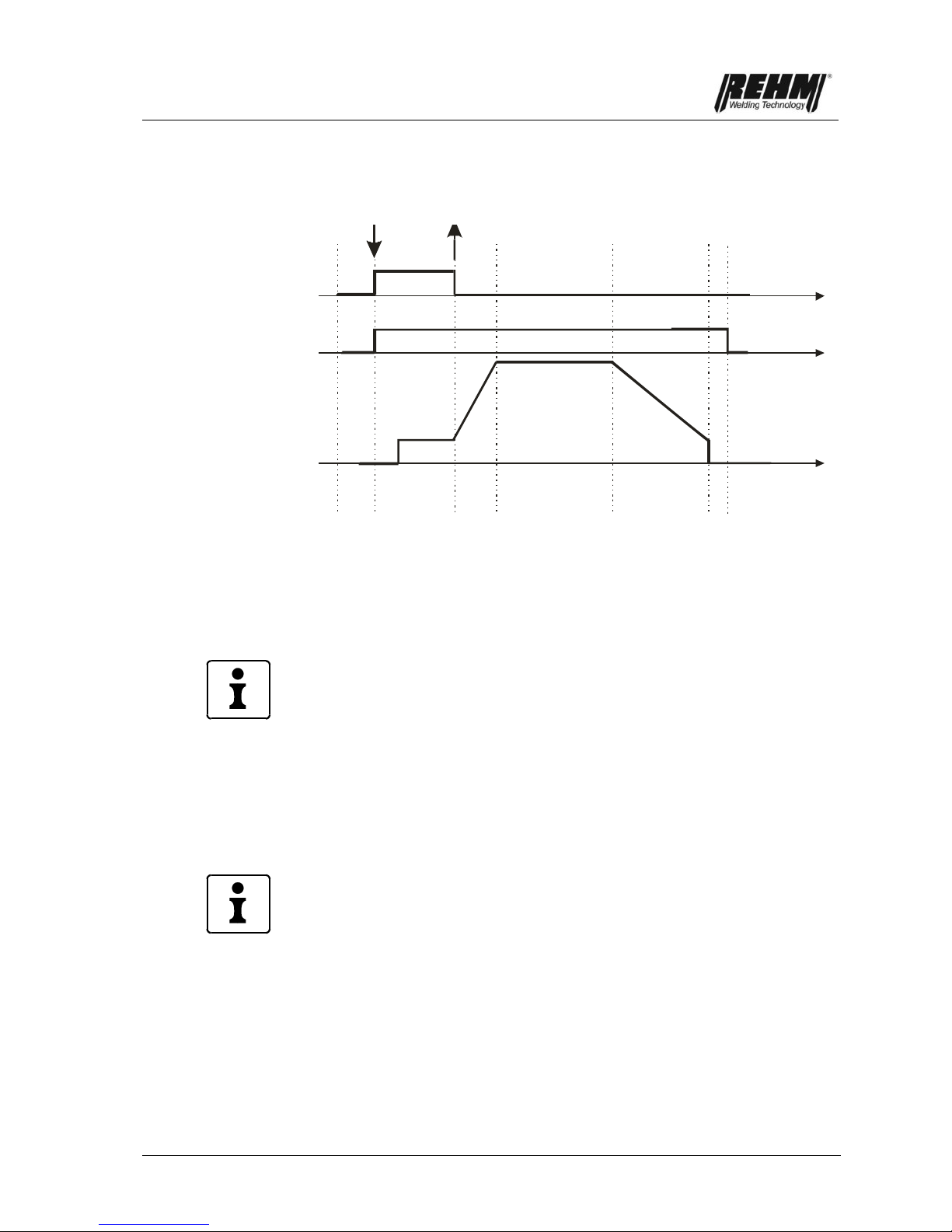
Fig. 6: 2-step spot welding procedure
1. Press torch step button
The set gas pre-flow time starts to run and the gas valve opens. The arc is
ignited after the gas pre-flow time has elapsed. The welding current automatically
sets itself to the starting current. After the upslope time has elapsed, the welding
current reaches the preset value I1. The set spot welding time starts to run. After
the spot welding time has elapsed, the current reduces in accordance with the
preselected downslope time to the value set for the end crater current, and
switches itself off automatically after the final current time has elapsed.
2. Release torch step button
The inert gas flows in accordance with the selected gas post-flow time.
2-step spot welding
Torch Button 1
Gas valve
Welding Current
Functional description
19
3.5.2.2 TIG spot welding, 4-step
t
t
t
4-Takt-Punkten
Brennertaster 1
Gasventil
Schweißstrom
Fig. 7: 4-step spot welding procedure
1. Press torch step button
The set gas pre-flow time starts to run and the gas valve opens. The arc is
ignited after the gas pre-flow time has elapsed. The welding current automatically
sets itself to the starting current. The starting current is retained until the torch
button is pressed.
Special features:
The start and end current time cannot be adjusted for 4-step spot welding
The procedure can be aborted at any time by pressing the torch button again, the
inert gas continues to flow in accordance with the selected gas post-flow time.
2. Release torch step button
The welding current automatically sets itself to the pre-selected value after the
upslope time has elapsed. The set spot welding time starts to run. The torch
button does not have to be pressed and released again for the 3rd or 4th step,
since the welding process runs automatically after the 2nd step has been
triggered.
The procedure can be aborted by pressing the torch button again. The
downslope time starts to run, and if the torch button is released during the current
reduction time, the jump to 0A occurs and the inert gas flows in accordance with
selected gas post-flow time.
After the spot welding time has elapsed, the current reduces in accordance with
the preselected downslope time to the value set for the end crater current, and
switches itself off automatically after the final current time has elapsed. The inert
gas flows in accordance with the selected gas post-flow time.
4-step spot welding
Torch Button 1
Gas valve
Welding Current
Functional description
20
3.5.3 WIG Interval
INVERTIG.PRO digital provides TIG interval welding as an additional welding
method. Interval welding means defined spot welding with defined interval times.
The application of extremely thin fillers is possible. Interval welding is only
possible in 2-step operating mode.
Welding in interval welding mode is recommended for welding with a fixed
interval time setting starting at 0.01 seconds.
In the WIG interval the interval time between the individual intervals can be set
individually and therefore the cooling of the base material can be guaranteed
less distortion.
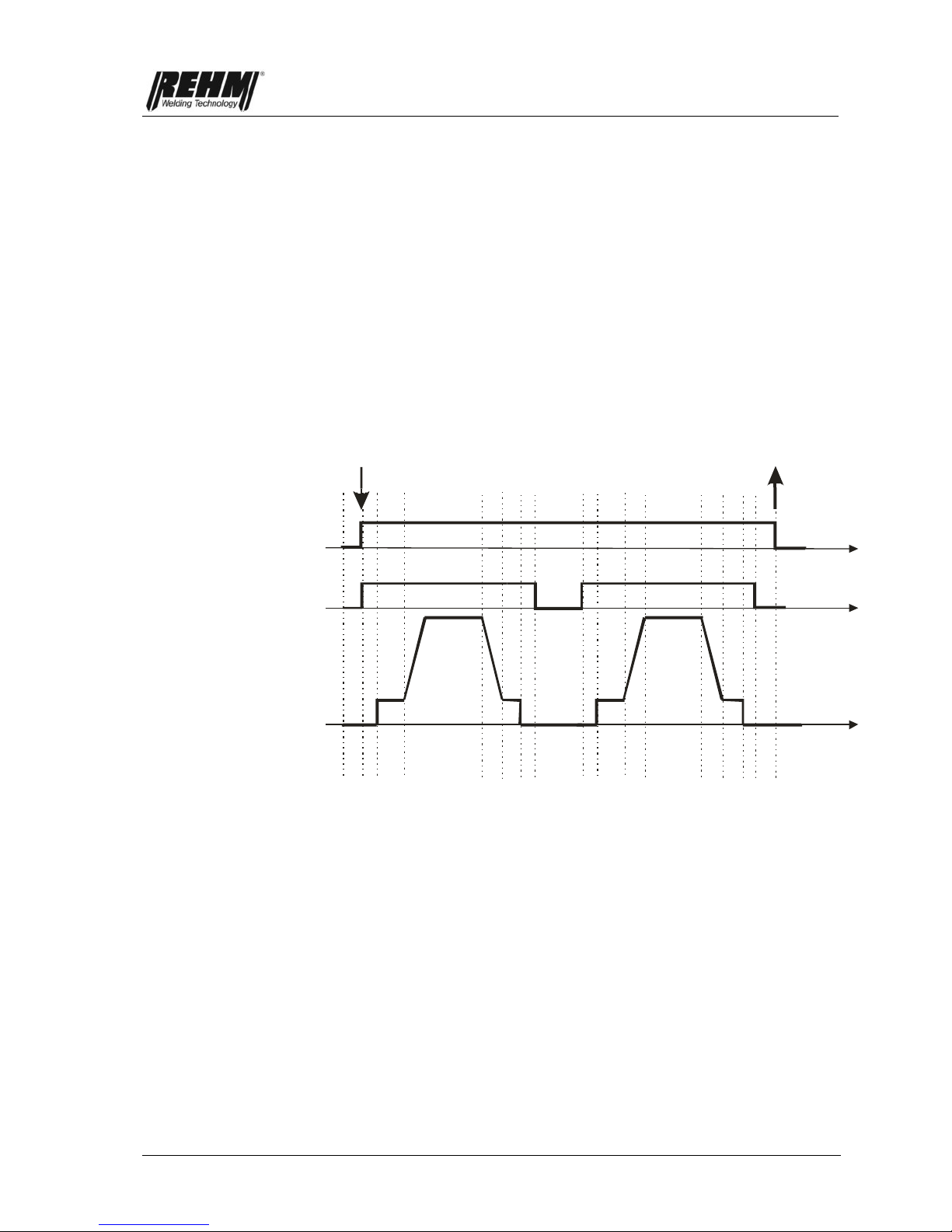
3.5.3.1 TIG interval, 2-step
t
t
2-Takt-Intervall
Brennertaster 1
Gasventil
Schweißstrom
t
Fig. 8: 2-step interval procedure
1. Press torch step button
The set gas pre-flow time starts to run and the gas valve opens. The arc is
ignited after the gas pre-flow time has elapsed. The welding current automatically
sets itself to the starting current. After the upslope time has elapsed, the welding
current reaches the preset value I1. The set interval time starts to run. After the
interval time has elapsed, the current reduces in accordance with the preselected
downslope time to the value set for the end crater current, and switches itself off
automatically after the final current time has elapsed, i.e. the welding current
goes to 0A. The inert gas continues to flow in accordance with the selected gas
post-flow time and the interval time runs down. Once the interval time has
elapsed, the welding current sets itself to the pre-selected start current again and
the welding process runs again as described.
2. Release torch step button
Interval welding stops.
2-step interval
Torch Button 1
Gas valve
Welding Current

Functional description
21
3.5.4 Electrode welding
The welding parameters for electrode welding are described in chapter 3.10.
The electrode is both an arc carrier and additional material at the same time. It
consists of an alloyed or non-alloyed core wire and a sheathing. The sheathing
has the job of protecting the melt bath from the damaging introduction of air, and
stabilising the arc. It also forms a slag that protects and shapes the seam. Almost
any metal can be welded using electrode welding. Electrode welding is a welding
method that is popular and easy to do.
3.6 The welding parameters
The welding parameters that are assigned in the welding curve that is shown are
selected using the push and rotate knob [7]. The setting facilities are always
selected and adjusted using the same principle.
3.6.1 Basic setting of welding parameters.
Rotate the push and rotate knob [7] to the required setting option (e.g. current
I1). The currently selected setting facility is displayed at the bottom centre of
the screen [12] and the associated value appears at the top centre of the
screen. A selected parameter is marked in orange.
Press the push and rotate knob [7] to select the setting option. The parameter
that is to be modified appears in blue text.
Rotate the push and rotate knob [7] until the required value is set.
Press the push and rotate knob [7] to confirm the setting option.
If no activity takes place for 20 seconds, the selected welding parameter is
exited automatically.
.

Functional description
22
Fig. 9: INVERTIG.PRO digital control panel
Welding parameter display
Push and rotate knob for selecting the welding parameters
The welding parameters are described in the following in the order shown in fig.
9.
3.6.2 Gas preflow time
The gas preflow time is set as described in Chapter 3.6.1.
The gas preflow time is the time in which the inert gas valve is opened after the
torch button 1 has been pressed in order to start a welding procedure, before the
arc is ignited. This causes the arc to be lit with an inert gas shielding layer, which
protects the electrode and the workpiece from burning out.
If the welding procedure is restarted during the gas post-flow time, the gas
preflow time is automatically set to 0 seconds by the processor controller. This
speeds up re-ignition, which saves time when tacking, for example.
3.6.3 Ignition energy
The ignition energy is set as described in Chapter 3.6.1.
The ignition energy can be adjusted to a value of between 10 and 100% when
igniting with high frequency or Lift Arc (infinitely variable).
Depending on the selected value for the ignition energy, the processor controller
defines a preselection for the required ignition process. This preselection can
now be adapted to the selected electrode (type, diameter), the gas type and the
respective welding task depending on the polarity by adjusting the ignition
energy.
During welding work with thin materials and small electrode diameters, less
ignition energy should be selected.
In AC welding systems "power ignition" is carried out with an ignition energy
setting of 90% or above, which makes ignition easier in harsh environments.

Functional description
23
3.6.4 Start current
The ignition energy is set as described in Chapter 3.6.1.
The starting current is the initial welding current that is set after the ignition
process. The setting is infinitely variable. Selecting a suitable starting current
makes the following possible:
Less stress on the electrode due to increasing current
Search arc during 4-step welding for moving to the start of the seam
Welding with reduced current at the beginning of the seam in the event of
edges or heat accumulation.
Fast heat introduction with values of greater than 100%. The starting current
can be set in percent or as a fixed value. The setting is made in the System
application.
3.6.5 Upslope time
The upslope time is set as described in Chapter 3.6.1.
The upslope time is the time during which the welding current undergoes a linear
increase from the starting current to the preselected current I1. During 2-step
welding the upslope time starts immediately after igniting the arc. During 4-step
welding the increase time starts after releasing the torch button 1 with the start
current flowing.
3.6.6 Welding current I1
The welding current I1 is set as described in Chapter 3.6.1.
The adjustable range for welding current I1 depends on the selected operating
mode and the machine model.
The following values can be set using the push and rotate knob [7] depending on
the selecting welding method:
INVERTIG.PRO
digital
240 DC / AC/DC
INVERTIG.PRO
digital
280 DC / AC/DC
INVERTIG.PRO
digital
350 DC / AC/DC
INVERTIG.PRO
digital
450 DC / AC/DC
TIG
3 A … 240 A
3 A … 280 A
3 A … 350 A
3 A … 450 A

Functional description
24
3.6.7 Welding current I2
Welding current I2 is set as described in Chapter 3.6.1.
The use of welding current I2 is only meaningful for TIG welding, and is therefore
only displayed if TIG welding is taking place. Welding current I2 is used when
pulsing (see chapter 3.9.1) and when two-current control is being used:
Two-current control:
General method of operation:
The use of two-current control allows the user to work with 2 different preset
currents when using a 2-button torch. In other words, you can switch between the
two values I1 and I2 when welding.
The changeover to I2 takes place for as long as torch button 2 is pressed. When
torch button 2 is released, a changeover to I1 occurs immediately. This setting
can be modified in the System application, see chapter 3.14.3 (torch function,
locking I2).
Examples of changeovers:
From high current to low current or vice-versa, e.g. due to a change of
welding position
Manual pulsing (see chapter 3.6.8)
Starting with high current I1 to warm up the workpiece, then welding with
lower current I2.
Starting with lower current I1 at workpiece edges, then welding with higher
current I2.
Changing over is possible during 2-step and 4-step operation without pulsing.
The following ranges can be set in accordance with welding current I1.
INVERTIG.PRO
digital
240 DC / AC/DC
INVERTIG.PRO
digital
280 DC / AC/DC
INVERTIG.PRO
digital
350 DC / AC/DC
INVERTIG.PRO
digital
450 DC / AC/DC
TIG
3 A … 240 A
3 A … 280 A
3 A … 350 A
3 A … 450 A
Current I2 setting takes place either by activating the I2 setting facility, and/or
extremely quickly and easily by pressing torch button 2 before the welding
procedure.
3.6.8 Downslope time
The downslope time is set as described in Chapter 3.6.1.
The downslope time is the time during which the welding current is linearly
reduced to the end crater current. The downslope time starts immediately after
releasing torch button 1 during 2-step welding. During 4-step welding the
reduction time is started by pressing torch button 1. Slowly reducing the welding
current prevents end craters and the associated cracks from forming. Reduction
stops immediately as soon as the torch button is released in 4-step operation.

Functional description
25
Manual pulsing:
If torch button 1 is pressed during the downslope time with the TIG 2-step
function, the welding current immediately jumps to the value used during welding.
Depending on the point in time during the downslope time the torch button is
pressed, the energy mid-point can be selected directly and is infinitely variable.
t
t
t
Fig. 10: Manual pulsing procedure
3.6.9 End crater current
The end crater current is set as described in Chapter 3.6.1.
The end crater current is the welding current to which the system is reduced at
the end of the welding procedure. The setting can be made between 10% and
100% of the selected current I1 (infinitely variable). Example: End crater current
40% and welding current I1 100 A -> end crater current 40A). The percentage
ratio can be set to a fixed value in the System application. Selecting a suitable
end crater current makes the following possible:
Prevents notches and end crater cracks at end of seam due to the melt
cooling too quickly.
Manual pulsing (see chapter 3.6.8)
Welding with reduced current at the beginning of the seam in the event of
edges or heat accumulation.
3.6.10 Gas post-flow time
The gas post-flow time is set as described in Chapter 3.6.1.
The gas post-flow time is the period of time after the arc has been extinguished
before the inert gas valve is closed. The post-flow of inert gas protects the
workpiece and the tungsten needle from the oxygen in the air until they have
cooled. However, the preselected gas post-flow time only takes effect if welding
has taken place previously. Accidentally pressing the button will not start the gas
post-flow timer running. This gas management function reduces gas
consumption.
Gas valve
Welding current
Torch button 1

Functional description
26
3.7 Polarity multifunction button
Pressing the multifunction button [9] selects the AC current polarity (AC), the DC
current positive terminal (DC +), the DC current negative terminal (DC -) and
Dual Wave. The setting facilities are always selected and set using the same
principle, see chapter 3.4.2.
During electrode welding, it must be ensured that the upper output connector is
always the negative terminal in all INVERTIG.PRO digital DC welding systems
3.7.1 AC current (AC)
With AC current welding, the polarity at the output connectors switches
continuously between positive and negative polarity. With TIG pulsing, TIG
interval and TIG and electrode welding, the torch and the electrode holder are
normally connected to the upper output connector. The use of AC current makes
it possible to weld aluminium and aluminium alloys. Electrode welding with AC
current has the advantage that the blowing effect is avoided.
As far as AC current polarity is concerned, the balance, frequency and the sine
wave, triangle, square wave and AC-Matic curve shape can be selected on the
basis of a graphical display.
Fig. 11: INVERTIG.PRO digital / Classic application control panel
Graphical display of sine wave curve and AC balance 65%

Functional description
27
3.7.1.1 AC balance (%)
The balance is set as described in Chapter 3.4.2.
The balance setting can only be made in connection with AC current welding in
the case of TIG. It ranges from -80% to +80% and makes it possible to influence
the arc shape, penetration and cleaning when welding aluminium within an
extremely broad range. The negative and positive welding current is extremely
evenly distributed in the centre position (50%). With increasing negative values
the proportion of the negative welding current increases (up to -80%) and the
positive proportion decreases. This makes the arc narrower and generates
deeper penetration with less electrode loading. With increasing positive values
the proportion of positive welding current is increased (up to +80%) and the
negative proportion decreases. The cleaning of the melt bath is improved by the
positive proportion. The arc becomes wider and the penetration is less deep. The
use of a negative value that is as high as possible with a sufficient cleaning effect
is recommended (factory setting - 65%).
Fig. 12: INVERTIG.PRO digital / Classic application control panel
Graphical display of AC balance
Functional description
28
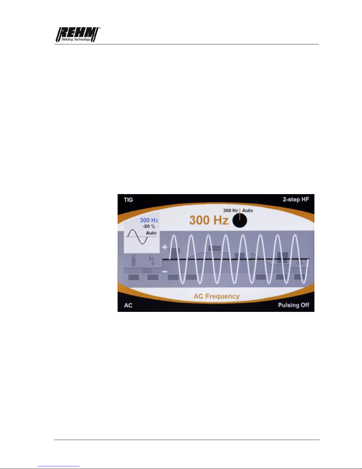
3.7.1.2 AC frequency Hz
The frequency Hz is set as described in Chapter 3.4.2.
The frequency setting can only be made in connection with AC current welding in
the case of TIG. The value for the frequency defines how frequently the output
polarity changes. The adjusting range ranges from 30 Hz to 300 Hz. For
example, at a frequency of 200 Hz the polarity change at the output connection
from plus to minus and back again takes place every 5 ms (=0.005 seconds).
The welding current is reduced to a value of zero whenever a polarity change
takes place, is re-ignited in the opposite direction and increased to the selected
welding current again. The sine wave shape that is used in this processcontrolled procedure leads to a considerable reduction in the amount of noise,
and has technical welding advantages in AC current welding.
REHM recommends setting to the automatic frequency system that has been
patented by REHM . The automatic frequency system automatically adapts the
AC frequency to the current strength. At low welding currents the AC arc is
focussed. This provides reliable root formation, e.g. in fillet welds in thin sheets of
metal. At higher currents the tungsten electrode load is reduced. A long service
life and optimum cost-effectiveness are the result. The automatic frequency
system has particular advantage when working with the iSystem P1 remote foot
controller.
Fig. 13: INVERTIG.PRO digital / Classic application control panel
Graphical display of frequency

Functional description
29
3.7.1.3 AC curve shape selection facility
Sine wave
Fig. 14: INVERTIG.PRO digital / Classic application control panel
Graphical display of sine wave curve
Triangle
Fig. 15: INVERTIG.PRO digital / Classic application control panel
Graphical display of triangle curve shape
Square wave
Fig. 16: INVERTIG.PRO digital / Classic application control panel
Graphical display of rectangle curve shape
AC-Matic
Fig. 17: INVERTIG.PRO digital / Classic application control panel
Graphical display of AC-Matic
Noise-optimised
Better penetration than
sine wave shape
Best penetration, low
electrode loading and even
better arc stability.
AC curve shape is automatically
adapted to current strength: With low
currents (< 180A) a sine wave curve
shape is automatically selected, and
higher currents (> 180A) the square
wave curve shape is used.

Functional description
30
3.7.2 DC current positive terminal
During TIG welding, TIG spot welding and TIG interval welding with DC current
positive terminal, the positive terminal is applied to the upper output connector
for the TIG torch.
During TIG welding, TIG spot welding and TIG interval welding with DC positive
terminal, the electrode is under extremely high thermal stress which can make
the electrode melt, even with small currents, and can cause damage. Welding
with DC current positive terminal is only possible using a REHM INVERTIG.PRO
digital AC/DC welding system.
During electrode welding the electrode holder is also connected to the upper
output connector. With the DC current positive terminal setting, the electrode is
welded with positive terminal. Electrode welding with DC current positive terminal
is only possible using a REHM INVERTIG.PRO digital AC/DC welding system.
With electrode welding, the polarity for the electrode is selected depending on
the type of electrode that is used (pay attention to electrode manufacturer
information).
3.7.3 DC current negative terminal
During TIG welding and TIG spot welding with DC current negative terminal, the
negative terminal is applied to the upper output connector for the TIG torch.
During TIG welding or TIG spot welding with DC current, welding usually takes
place with this setting.
During electrode welding the electrode holder is also connected to the upper
output connector. The electrode is welded with negative terminal with the DC
current negative terminal setting. During electrode welding with an
INVERTIG.PRO digital DC welding system at the positive terminal, the electrode
holder must be plugged into the lower connector, since the polarity is not
selectable. With electrode welding, the polarity for the electrode is selected
depending on the type of electrode that is used (pay attention to electrode
manufacturer information).
3.7.4 Dual Wave
The Dual Wave process from REHM is a combination of AC and DC welding.
The AC and DC times can be adjusted independently of each other The selected
values for welding current I1 and I2, the frequency and the balance are taken
into consideration in the same way as they are in DC-only or AC-only welding.
AC time DC time
Fig. 18: Individual AC and DC time settings
The Dual Wave process reduces the excess AC part in the arc to the necessary
minimum. The reduced heat introduction that this causes makes it easier to
control the welding bath and produces less pore formation, and is used in difficult
welding situations, when welding workpieces of different thickness and when
processing thin plates made from aluminium and aluminium alloys.

Functional description
31
Fig. 19: INVERTIG.PRO digital / Classic application control panel
Dual Wave time AC setting
When selecting the Dual Wave polarity, a graphical display of the selected
setting appears at the top left of the screen: The AC and DC times can also be
individually set between 0.1 and 10.0 seconds using the graphic.
Fig. 20: INVERTIG.PRO digital / Classic application control panel
Graphical display top left, AC frequency (auto), AC balance view
(65%), AC curve shape, Dual Wave AC and DC time (2.5 s and 0.5 s)
3.8 Multifunction button 2- / 4-step and high
frequency
By pressing the multifunction button [5] you can select 2-step with high
frequency, 4-step with high frequency, 2-step with Lift Arc or 4-step with Lift-Arc.
The setting options are always selected and set using the same principle, see
chapter 3.4.2.

Functional description
32
3.8.1 2-step function
2-step welding is recommended for fast, controlled tacking and manual spot
welding.
1st step: Press torch button
Solenoid valve for inert gas is opened.
The arc is ignited after the set gas pre-flow time has elapsed.
The welding current sets itself automatically to the preselected value for I1 during
the selected increase time starting with the selected start current.
2nd step: Release torch button
The current reduces with the preselected downslope time to the value set for the
end crater current, and then switches itself off automatically.
The inert gas flows in accordance with the selected gas post-flow time.
Fig. 21: Procedure for 2-step welding
Special features:
Re. 2nd step By pressing the torch button again during current reduction, the
welding current can be abruptly reset to I1. This procedure is
known as manual pulsing (see chapter 3.6.8). Pressing torch
button 2 (BT2) extinguishes the arc.
3.8.2 4-step function
Continuous button pressing is not required with 4-step welding, which means that
the torch can be guided for a longer time without fatigue.
4-step function procedure:
1st step: Press torch button
Solenoid valve for inert gas is opened.
The arc is ignited after the set gas pre-flow time has elapsed.
The welding current has the value set for the starting current.
2nd step: Release torch button
The welding current automatically sets itself to the pre-selected value for I1
during the preselected upslope time.
Gas valve
Welding current
Torch button 1
t
t
t

Functional description
33
3rd step: Press torch button
The current reduces with the preselected downslope time to the value set for the
end crater current.
The welding current flows with the value set for the end crater.
4th step: Release torch button
The arc is extinguished.
The inert gas flows in accordance with the selected gas post-flow time.
Fig. 22: Procedure for 4-step welding
Special features:
re. 2nd step Pressing the torch button again during the upslope time causes the
arc to be extinguished and the inert gas flows in accordance with
the selected gas post-flow time.
re. 3rd step The arc can be switched off during the downslope time. Releasing
the torch button before reaching the end crater current causes the
arc to be extinguished and the inert gas flows in accordance with
the selected gas post-flow time.
3.8.3 Welding with high frequency (HF)
The REHM TIG welding systems are equipped with HF ignition devices as
standard. In the "Electrode" setting, HF ignition is automatically switched off.
The HF ignition device makes contact-free ignition of the arc possible between
the electrode and the workpiece by pre-ionising the air gap during DC and DC
current welding, whereby tungsten inclusions and therefore welding errors are
prevented. In both cases the HF ignition device is switched off again after ignition
has taken place. The re-ignition of the arc that is described in chapter 3.7.1 takes
place without using the HF ignition device. This reduces the radiation of electrical
interference fields and even makes it possible to carry out AC current welding
without HF ignition, as is already known from DC current welding (see chapter
3.8.4).
With the high frequency setting the HF ignition device is ready for operation. In
order to ignite the arc, the electrode is held about 3-5 mm above the workpiece.
When the torch button is pressed, the gap is ionised by a high-voltage pulse and
the arc is created. The contactless ignition prevents tungsten inclusions in the
weld seam. During welding, the HF ignition device is automatically switched off
again after ignition has taken place.
Torch button 1
Gas valve
Welding current
t
t
t
Functional description
34
3.8.4 Welding with Lift-Arc
When welding with DC or AC current, contact ignition (Lift-Arc) can be carried
out. The high frequency is switched off when doing this. In order to ignite the arc,
the electrode is applied and the torch button is pressed. When the electrode is
raised, the arc ignites under program control and without wearing the sharpened
electrode. This facility may be advantageous when working on sensitive
electronic devices (e.g. in hospitals, when carrying out repair welding on CNCcontrolled machinery), if there is a risk of interference from high-voltage pulses.
3.9 Pulsing multifunction button
The multifunction button [6] is pressed to select time pulsing, hyper pulsing® and
no pulsing (pulsing off). The setting options are always selected and set using
the same principle, see chapter 3.4.2.
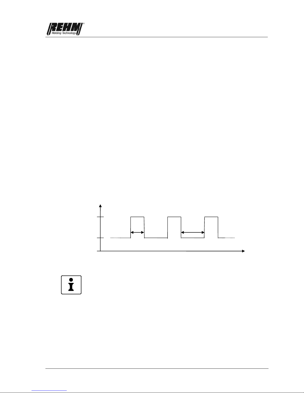
3.9.1 I1 pulsing time t1
The I1 pulse time t1 is set as described in Chapter 3.4.2. TIG welding, TIG spot
welding and TIG interval welding with pulse function can basically be divided into
two areas:
1. Time pulsing with pulse times between 0.1 and 5.0 seconds
2. Hyper-pulse with pulse frequencies between 10 Hz and 15 kHz
During TIG pulse welding, automatic switching between currents I1 and I2 takes
place continuously. When doing this you have free choice of which current is the
bigger high current and which is the smaller low current.
Fig. 23: Welding current when pulsing
Pulsing can be switched off and on again during welding by pressing torch button
2. If torch button 2 is pressed with a pulsing welding current, pulsing is switched
off and welding continues with welding current I2. Welding can continue with
welding current I2 until a new filler is taken, for example, and welding is
continued with a pulsing welding current by pressing torch button 2 again.
Time pulsing: Pulsing with pulse times of 0.1 to 5.0 seconds
The settings for I1 pulsing time t1 and I2 pulsing time t2 determine the length of
time for which currents I1 and I2 should be active until switching over to the other
current. Both pulse times can be set independently of each other
The times and the welding current levels should be coordinated in such a way
that the base material is melted during the high current phase and solidifies again
during the low current phase. Because of TIG pulse welding, the weld pool is
easier to control in difficult situations (particularly in dilemmas and with large
gaps to bridge) and when welding thin sheets of metal than with a constant
welding current.
Current I1
Current I2
I1 pulse time t1
I2 pulse time t2
Time
0

Functional description
35
Hyperpulse: with pulse frequencies of 10 Hz to 15 kHz
The course of the welding current corresponds to conventional pulsing. However,
the periods of time for which currents I1 and I2 respectively are active are always
the same. Since these time periods are extremely short, it is meaningful and
normal to refer to them as pulse frequencies.
The following relationships apply for converting the pulse frequency into the
respective pulse times t1 and t2:
Total pulse time = I1 pulse time t1 + I2 pulse time t2 = 1 / pulse frequency
I1 pulse time t1 = I2 pulse time t2 = 0.5 * total pulse time
Example:
Pulse frequency = 50 Hz
Total pulse time = I1 pulse time t1 + I2 pulse time t2 = 1 / 50 Hz = 20 ms = 0.02 s
I1 pulse time t1 = 0.5 * total pulse time = 0.01s
I2 pulse time t2 = 0.5 * total pulse time = 0.01s
This means that the current has the value of current I1 for 0.01 s (=10 ms) during
welding, then the value of current I2 for 0.01 s (=10 ms), then the value of current
I2 again for 0.01 s (=10 ms) etc.
Pulsing with such short times results in a narrower and more concentrated arc
and deeper penetration.
3.9.2 I2 pulse time t2
The settings are made in accordance with I1 pulse time t1 (see chapter 3.9.1).
3.10 Electrode welding parameters
The electrode welding procedure is selected using the multifunction button [8].
The setting of electrode welding parameter welding current I1, Arc Force, Hot
Start and Hot Start Time is carried out as described in Chapter 3.4.2.
When making the settings for electrode welding, please ensure that no TIG torch
is connected. Failure to do this will result in error number "E021" being displayed
on the screen (see Chapter 7.3).
3.10.1 Welding current I1 during electrode welding
Welding current I1 can be set using the push and rotate knob [7] (infinitely
variable).
The Dual Wave procedure enables better control of the welding bath and,
particularly in difficult welding positions, when welding work pieces of differing
thicknesses, and is used for processing thin sheet like aluminium and aluminium
alloys.

Functional description
36
INVERTIG.PRO
digital
240 DC / AC/DC
INVERTIG.PRO
digital
280 DC / AC/DC
INVERTIG.PRO
digital
350 DC / AC/DC
INVERTIG.PRO
digital
450 DC / AC/DC
Electrode
3 A … 240 A
3 A … 280 A
3 A … 350 A
3 A … 450 A
3.10.2 Arc Force
In order to have a stable arc during electrode welding, it is important to make the
drip-shaped material transitions easier by adding extremely short current pulses
to the selected welding current I1. The magnitude of these current pulses is
determined by the Arc Force that is selected. The Arc Force can be set to a value
between 0% and 300% (infinitely variable) using the push and rotate knob [7]
with the Rutil and Basic electrode type selected, and between 100% and 300% of
the selected current I1 with cellulose electrode type selected (but a maximum of
Imax, e.g.: Arc Force 50% and welding current I1=100A -> ArcForce 150A)
3.10.3 Hot Start
For better ignition of the electrode during electrode welding, a higher current than
the selected welding current I1 is briefly used at the start of welding. The
magnitude thereof is determined by the Hotstart setting. The setting can be made
between 0% and 200% of the selected current I1 (infinitely variable) using the
push and rotate knob [7] (but max. Imax, e.g.: Hotstart 30% and welding current
I1=100A -> Hotstart 130A). The Hotstart time can be set to between 0.1 and 10
sec. (infinitely variable).
3.10.4 Anti-Stick Function
If a permanent short circuit occurs during electrode welding, the anti-stick
function is activated after about 0.3 sec., which limits the current to approx. 20 A.
This prevents the electrode from wearing out and the permanent short circuit can
be easily remedied by stripping.
3.11 Quick setting P1 and P2 (Quick Choice buttons)
Pushbuttons P1 [10] and P2 [11] allow the user to load and save two programs
quickly.
In order to load program 1 or program 2, briefly press the multifunction button P1
or P2.
To save the machine settings that have been made, press and hold down
pushbutton P1 [10] or P2 [11] for approx. 2 seconds in the Classic application.
When the program has been saved, P1 or P2 appears at the top right of the
screen.
Program P1 or P2 can also be called up using Up/Down torch (see Chapter
3.14).
3.12 Programs application (Progr.)
The Programs application (Progr.) allows up to 1000 programs to be loaded,
saved and managed in up to 100 folders. The programs can be saved and

Functional description
37
loaded under a freely selectable name (e.g. name of an employee, customer
and/or material) in a freely selectable folder. The values for all setting options
provided by the machine are saved and loaded for each program.
This means that device settings that have been determined for repeated welding
tasks can be set again on the welding device within seconds. This saves time
and provides consistent quality.
Also, the individual basic settings of the welding device such as start and end
crater current, ignition energy etc. can be saved and quickly retrieved again for
each person if the equipment is being used by several persons.
As a special feature, the INVERTIG.PRO digital welding system provides quick
loading and saving of 2 programs, P1 [10] and P2 [11], see chapter 3.11. In the
Progr. application [2] P1 and P2 can be selected, but the saved settings cannot
be modified or deleted.
The green border colour indicates that you are in the Programs application.
Fig. 24: INVERTIG.PRO digital / Programs application (Progr.) control panel

Functional description
38
3.12.1 Managing folders
Creating a new folder
If you press the Progr. application button [2] you will be taken to the Programs
application (Progr.)
Rotate the push and rotate knob [7] to "New Folder"
Pushing the push and rotate knob [7] allocates a default name for this folder.
Fig. 25: INVERTIG.PRO digital / Programs application (Progr.) control panel
New folder
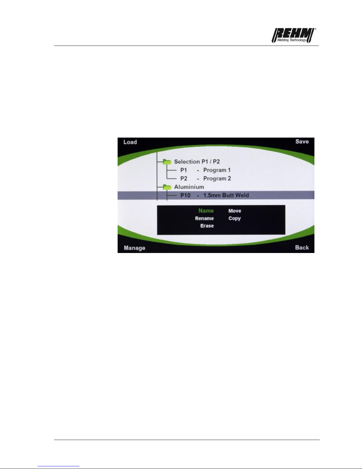
Managing existing folders
If you press the Progr. application button [2] you will be taken to the Programs
application (Progr.)
Rotate the push and rotate knob [7] to the required folder
Press the multifunction button [9] to edit the folder. The following options are
available: Name, Rename, Delete, Move.
Fig. 26: INVERTIG.PRO digital / Programs application (Progr.) control panel
Managing existing folders
Functional description
39
3.12.2 Main management settings
Pressing the "Progr." application button [2] takes you to the Programs
application (Progr.)
Pressing the multifunction button [9] takes you to the Management menu.
Rotate the push and rotate knob [7] to the required action (e.g. Name,
Rename, Delete, Move, Copy).
Press the push and rotate knob [7] to select the action.
If no activity takes place for 20 seconds, the selected menu is exited
automatically.
Fig. 27: INVERTIG.PRO digital / Programs application (Progr.) control panel
Management selection: Name, Rename, Delete, Move, Copy.
3.12.2.1 Management: Name / Text Entry
The setting options are always selected and set using the same principle, see
chapter 3.12.2.
The letters, numbers and symbols are arranged on the screen in the same
way as they are on the control panel (see fig. 28). The letters, numbers and
symbols are selected by pressing the application and multifunction buttons on
the control panel.
The required letter, number or symbol is selected by pressing the respective
application or multifunction button several times.
Upper and lower case can be selected by pressing the push and rotate knob
[7].
Characters that have been selected by mistake can be deleted again by
pressing the application button [3].
Once the required name has been entered, saving takes place by pressing
the application button [2]. The name has been saved.
The "Name" menu can be exited again without saving by pressing the
application key [4].

Functional description
40
Fig. 28: INVERTIG.PRO digital / Programs application (Progr.) control panel
Text entry
3.12.2.2 Management: Rename
See Management: Name procedure in Chapter 3.12.2.1
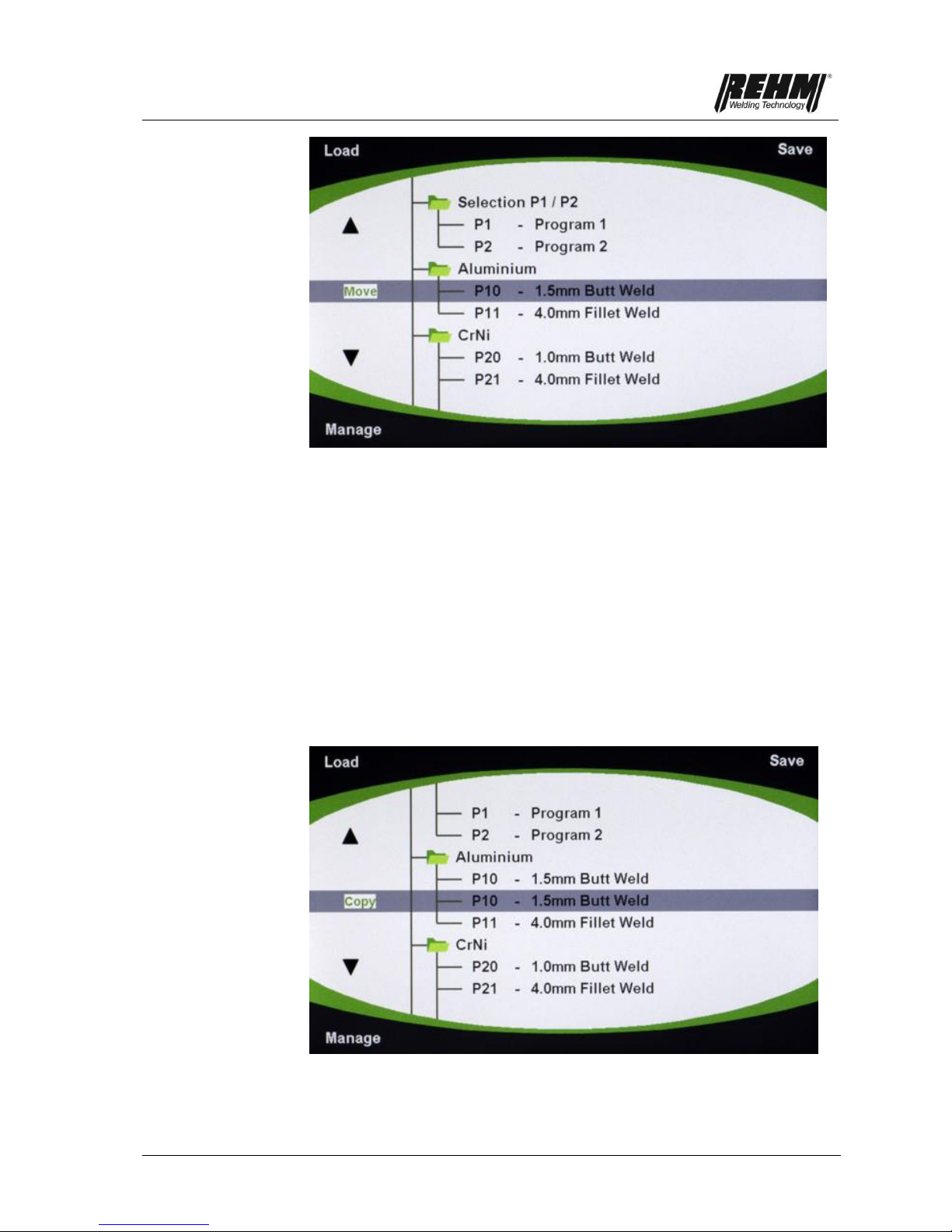
3.12.2.3 Management: Move
The setting options are always selected and set using the same principle, see
chapter 3.12.2.
Rotate the push and rotate knob [7] to the folder to be moved in order to move
the selected folder or program to the required location. "Move" appears in
green text at the left-hand edge of the screen next to the folder or program to
be moved.
Press the push and rotate knob [7] to confirm.
Rotate the push and rotate knob to the new position for the folder.
Press the push and rotate knob [7] to confirm.
Functional description
41
Fig. 29: INVERTIG.PRO digital / Programs application (Progr.) control panel
"Move" appears in green text next to the folder/program.
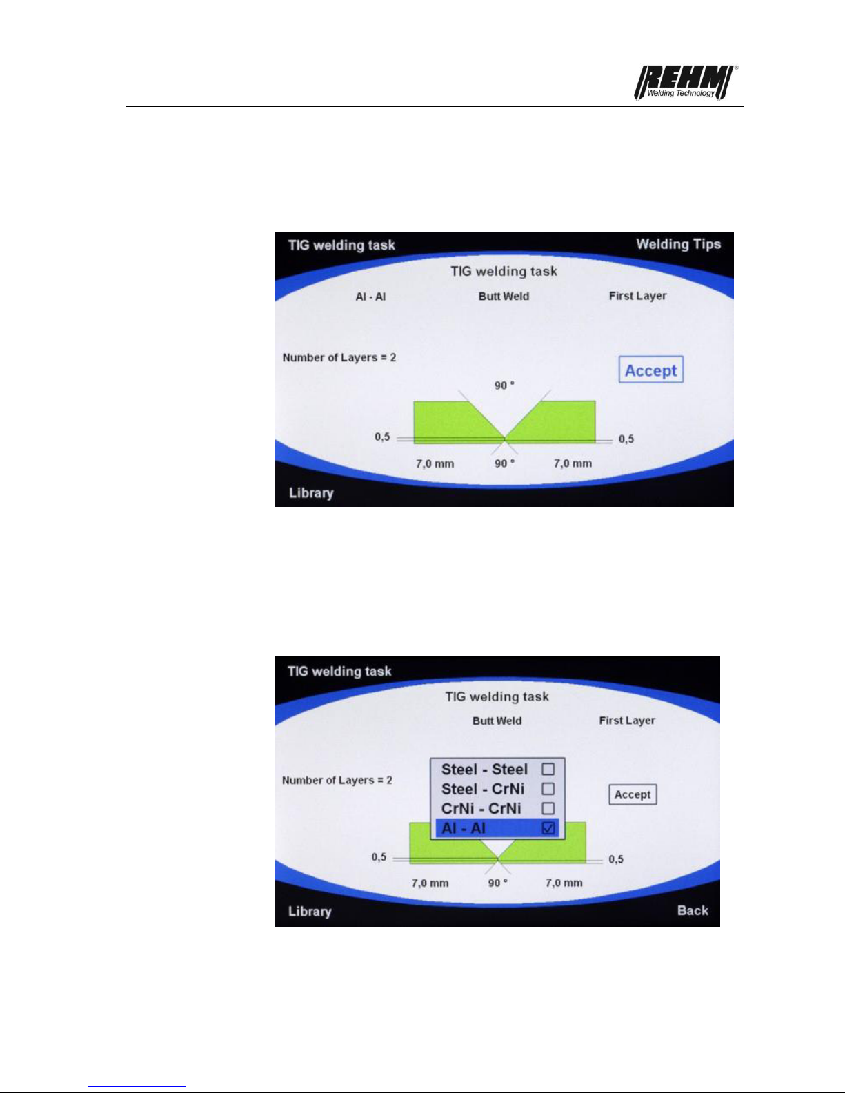
3.12.2.4 Management: copy
Select program to be copied using the push and rotate knob [7]. The selected
program can be displayed by pressing the push and rotate knob [7]. Display
mode is exited by pressing the push and rotate knob again.
The setting options are always selected and set using the same principle, see
chapter 3.12.2.
Rotate the push and rotate knob [7] to select the position to which the
program is to be copied. "Copy" appears in green text at the left-hand edge of
the screen next to the program to be copied.
Press the push and rotate knob [7] to confirm. The copied program is saved
under the next free program number.
Fig.30: INVERTIG.PRO digital / Programs application (Progr.) control panel
"Copy" appears in green text next to the folder/program.

Functional description
42
3.12.2.5 Management: Delete
Select folder or program to be deleted using the push and rotate knob [7].
Pressing the multifunction button [9] takes you to the Management menu.
Rotate the push and rotate knob [7] to the required action, Delete.
Press the push and rotate knob [7] to select the action.
Rotate the push and rotate knob [7] to Delete "Yes" or "No".
Press the push and rotate knob [7] to confirm the selection.
Fig. 31: INVERTIG.PRO digital / Programs application (Progr.) control panel
Delete view? Yes/No
3.12.3 Loading programs
Rotate the push and rotate knob to select the required program.
The parameters of the program can be displayed on the Classic display by
pressing the push and rotate knob. No values can be modified in this view.
Pressing the push and rotate knob again takes you back to the overview.
Press the Load multifunction button [8]. The program is loaded.
The loaded program has a grey background. The program number appears in
green text on the left-hand edge of the display, next to the loaded programs.

Functional description
43
Fig. 32: INVERTIG.PRO digital / Programs application (Progr.) control panel
The loaded program has a grey background
Press the Classic application button [1]. The loaded program is displayed. The
program number appears in green text at the top right of the screen [12].
Fig. 33: INVERTIG.PRO digital / Classic application control panel
The loaded program number appears in green text at the top right.
3.12.4 Saving programs
Make the required machine settings (welding parameters) in the Classic
application [1].
Press the Progr. application button 2.
Select the required folder using the push and rotate knob [2].
Pressing the push and rotate knob [7] will cause the contents of the folder to
be displayed.

Functional description
44
Use the push and rotate knob [7] to select the required program in which the
new program will be saved. It is possible to overwrite an existing program or
create a new one.
Press Save multifunction button [5]. The program has been saved.
A new program is stored under the next free program number.
If an existing program is being overwritten, you must reply with "Yes" or "No"
to the question "Overwrite?" after pressing the multifunction button [5].
Fig. 34: INVERTIG.PRO digital / Programs application (Progr.) control panel
Overwrite? Yes/No
Functional description
45
3.13 Assist Application
Pressing the Assist application button [3] takes you to the Assist application. The
Assist application [3] allows you to enter a welding task in order to obtain
suggestions for the optimum parameters for the welding task. The following
values / data can be entered.
Fig. 35: INVERTIG.PRO digital / Assist Application control panel
Data / value entry selection option
Select materials
Select weld type (butt weld / fillet weld)
Select material thickness for both components to be joined
Layer selection, first or other layers
The material thickness of the materials to be joined can be set using a graphic.
The blue border colour indicates that you are in the Assist application.
Fig. 36: INVERTIG.PRO digital / Assist application control panel
Material selection
Functional description
46
3.13.1 Setting the welding task
Rotate the push and rotate knob [7] to the specified points
You are taken to the selection by pressing the push and rotate knob [7].
Rotate the push and rotate knob [7] to the required setting.
Press the push and rotate knob [7] to confirm the setting.
Press the push and rotate knob [7] again to leave the point.
The material thickness can be set on the displayed graphic using the push and
rotate knob [7]. Note: If the material thicknesses differ considerably, the Assist
application does not calculate a suggestion. "D1-D2 too great!" appears on the
TFT display.
After entering all of the required data, select the "Accept" field using the push
and rotate knob [7]. The welding parameters are then accepted.
Press the push and rotate knob [7] to accept the data.
The colour of the "Accept" text will be red whilst the data is being loaded.
Fig. 37: INVERTIG.PRO digital / Assist application control panel
Accept loading procedure
When loading is complete, "Accepted" is displayed black. Note: The device is
now ready for welding. There is no need to switch to the Classic application.

Functional description
47
Fig. 38: INVERTIG.PRO digital / Assist application control panel
Welding task accepted
If you press the Classic application button [1], the optimum parameters for the
welding task will be displayed on the Classic screen. "Assist" appears in blue
text at the top right of the screen [12].
Fig. 39: INVERTIG.PRO digital / Classic application control panel
Display optimum welding parameters for welding task
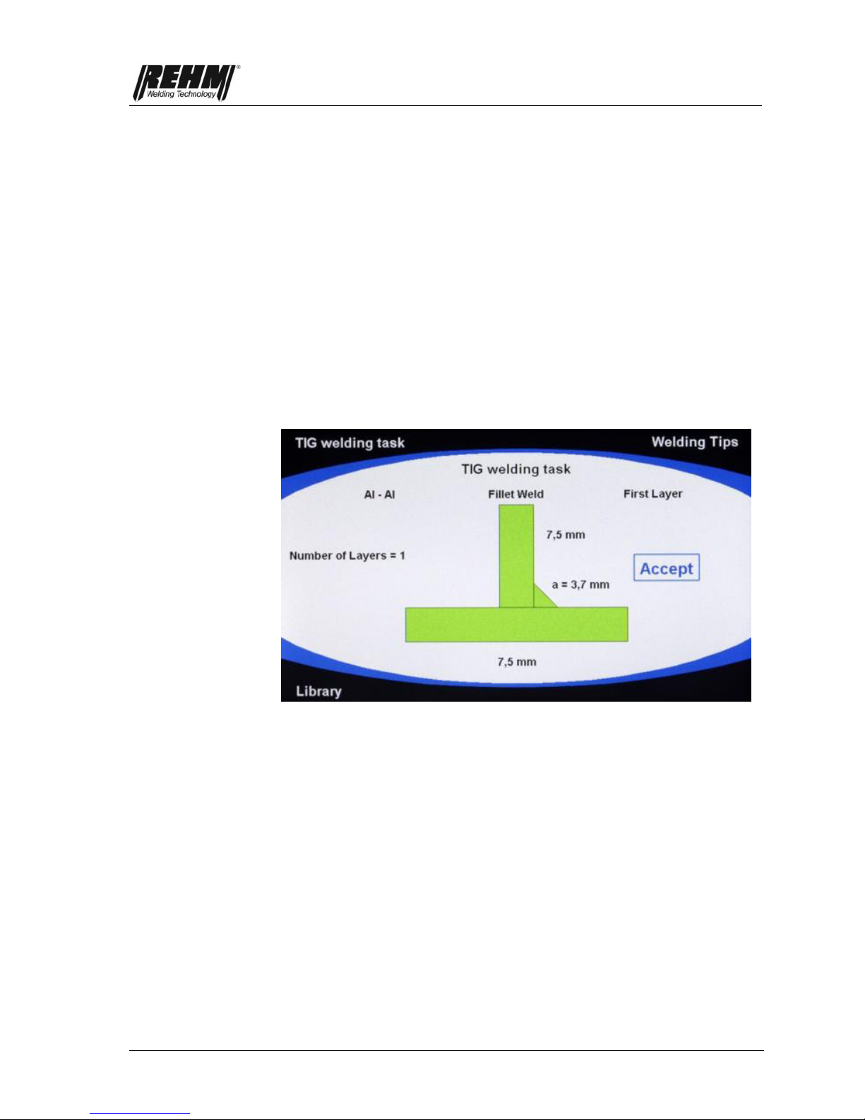
3.13.2 Welding tip
The welding tip is called up by pressing the multifunction button [5]. As well as
the parameters, additional practical information for the welding task is suggested
in the welding tip such as the gas nozzle size, the preheating temperature, the
electrode type etc.
The information in the welding tip cannot be modified or overwritten.
The welding tip cannot be called up until the entered Assist values for the
welding task have been determined.

Functional description
48
Fig. 40: INVERTIG.PRO digital / Assist application welding tip
3.13.3 Library
The library is called up by pressing the multifunction button [9]. The library is a
comprehensive technical database to do with welding, and provides information
about gas, fillers, electrodes, types of seam and welding position.
Fig. 41: INVERTIG.PRO digital / Assist application control panel
Library view
Fig. 42: INVERTIG.PRO digital / Assist application control panel
Library view WIG electrodes and welding position
Functional description
49
3.14 System application button
Pressing the application button [4] takes you to the System application. System is
the application with which functions and procedures can be defined in an
extremely convenient and clear way.
The yellow border colour indicates that you are in the System application.
Fig. 43: INVERTIG.PRO digital / Assist application control panel
Settings view
3.14.1 System overview
Pull-down menus provide clarity and allow you to make quick changes.
Fig. 44: Overview of System application and pull-down menu

Functional description
50
3.14.2 Basic selection of machine settings
Rotate the push and rotate knob [7] to the required setting.
Press the push and rotate knob [7] to display the selection of the setting to be
modified.
Rotate the push and rotate knob [7] to the required point.
Press the push and rotate knob [7] to confirm the selection.
The settings in the System application are described in the following.
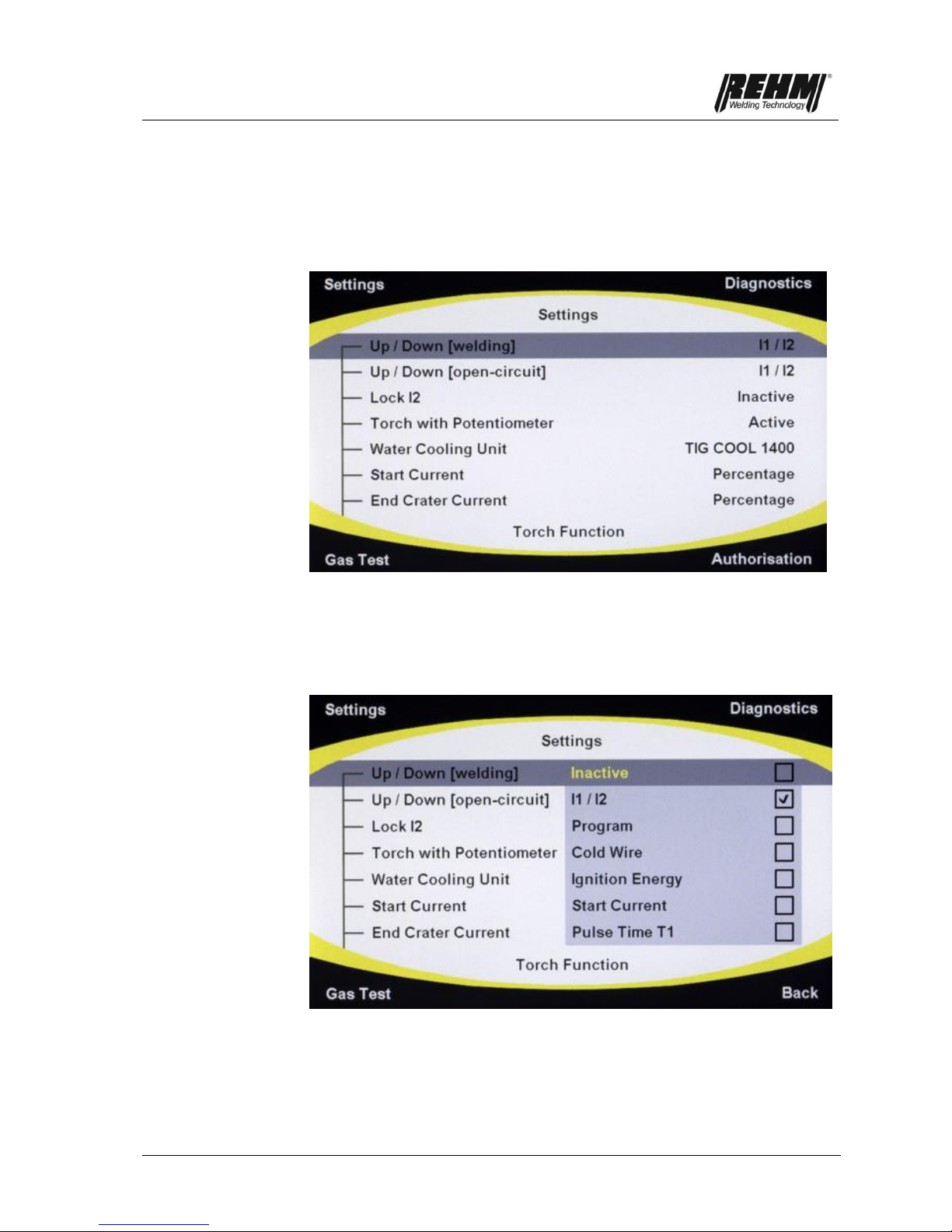
3.14.3 Explanation of system settings
Torch Up/Down welding function
This setting is provided for the use of an Up/Down torch The following settings
can therefore be made for the Up/Down torch for welding operation.
Inactive
→ Up-/Down torch is inactive, i.e. Up-Down function not present
I1/I2
→ Welding current I1 or I2 can be modified for the Up/Down torch. The I1/I2
relationship is maintained when pulsing.
Program
→ With the Up/Down torch, all programs can be called up within a program
sequence.
Other setting options:
Cold wire, only when using the REHM APUS series cold wire device (start
and end of wire feed is carried out using the Up button; cold wire retraction is
carried out using the Down button), ignition energy, start current, pulse time
t1, Pulse time t2, pulse frequency, end crater current, AC balance, AC
frequency, current I1, Current I2, gas pre-flow time, start current time, upslope
time, downslope time, end crater current time, gas post-flow time, AC time,
DC time, pulse type, AC curve type, spot welding time, interval time
Torch idling Up/Down function
The Up/Down function of the torch can be set in the following ways during
standby operation, i.e. not during welding operation.
Inactive. I1/I2, cold wire (start and end of wire positioning in 2nd step), ignition
energy, start current, pulse time t1, Pulse time t2, pulse frequency, end crater
current, AC balance, AC frequency, current I1, Current I2, gas pre-flow time,
start current time, upslope time, downslope time, end crater current time, gas
post-flow time, ignition, operating mode, polarity, AC time, DC time, pulse
type, AC curve type, spot welding type, welding procedure, interval time
Torch I2 locking function
Inactive
→ I2 locking is inactive, i.e. I2 is only active for as long as torch button 2 is
pressed.
Active
→ I2 locking is active, i.e. the changeover from I1 to I2 during welding takes
place in such a way that pressing torch button 2 provides a constant
changeover to the other current. Pressing torch button 2 again switches
back to I1.

Functional description
51
Torch poti-torch function
This setting is intended for the use of a torch with a potentiometer.
Inactive
→ Torch potentiometer is inactive, i.e. the potentiometer at the torch is not
evaluated
Active
→ Torch potentiometer is active, i.e. the value set at the potentiometer is
evaluated
Water cooling device
TIG COOL 1400
→ Welding with a water-cooled torch is possible without a water cooling
device being detected by the welding system, e.g.: TIG -COOL CART
1400, or other water cooling device without a communication interface.
TIG COOL 2000
→ Welding with water-cooled torch is only allowed if the wending system
detects the use of a functioning water cooling device, e.g. TIG-COOL
CART 2000. Otherwise an error message occurs, which prevents
damage to the welding torch if no water cooling device is present.
Classic application start current
Percentage or absolute
→ Start current is set percentage-wise to I1 or can be set to an absolute
value
Classic application end crater current
Percentage or absolute
→ End crater current is set percentage-wise to I1 or can be set to an
absolute value
Classic E-manual polarity function
Manual or auto (automatic changeover of torch connector polarity –
depending on the selected electrode type): Note: The Auto function can only
be selected for INVERTIG.PRO digital AC/DC welding systems.
Mode sequence program function
Selection of "limiting" or "rolling" program sequence in the programs
application (Progr.). All programs within a folder belong to a program
sequence. The programs within this sequence can be loaded via the torch
Up/Down buttons. The type of loading can be "rolling" or "limiting".
Limiting
→ The loading of the programs within a program sequence ends with the
first or last program, i.e. no fast access is possible from the first to the
last program, because scrolling through is required at the end of the
program.
Rolling
→ The program in last position can be loaded immediately from the
program that is stored on first position (rotating).

Functional description
52
Welding device language
Fig. 45: Overview of System application with language selection pull-down menu

Functional description
53
Welding device factory settings
Fig. 46: Overview of System application / factory settings
The factory settings are set by pressing the push and rotate knob twice. The
programs and the settings in the System application are retained.
Welding parameters
Factory setting
Gas preflow time
0.1 s
Ignition current
50%
Start current
50%
Upslope time
0.1 s
Current I1
100 A
Current I2
80 A
Pulse time t1
0.3 s
Pulse time t2
0.3 s
Downslope time
0.1 s
End crater current
20%
Gas post-flow time
5.0 s
AC frequency*
Automatic
AC balance*
- 65%
Ignition
HF on
Operating mode
2 step
Polarity*
DC Minus
EL current I1
150 A
Hot-Start current
70%
Arc Force current
70%
Pulse type
Pulses off
Pulse frequency
500 Hz
* not used in DC systems
Fig. 47: Factory settings overview

Functional description
54
3.14.4 Gas test
The gas test is carried out by pressing the multifunction button once [9] for the
factory set time of 20 seconds. The gas test can be prematurely terminated by
pressing the multifunction button [6].
Fig. 48: INVERTIG.PRO digital / System application control panel
Gas test view
3.14.5 Access authorisation
An increasing number of companies stipulate fixed parameters for certain tasks
in order to safeguard quality
However, users have different preferences and capabilities For example, in terms
of welding speed and the associated welding currents The access authorisation
for the INVERTIG.PRO digital takes this into account and makes individual
adaptation possible.
The INVERTIG.PRO digital gives the user the possibility of providing preset
welding data records with access authorisation and a parameter tolerance range
of 0% to 30%.
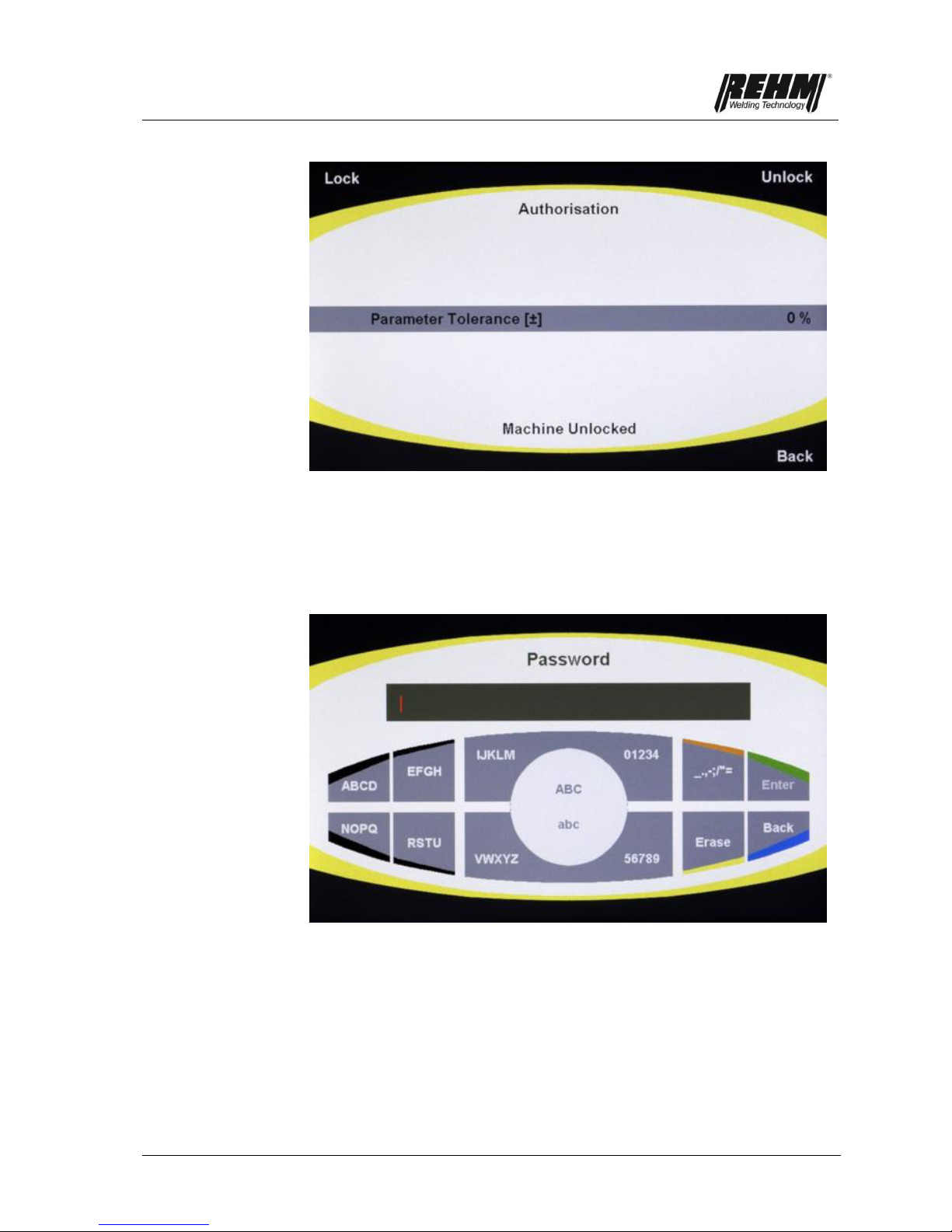
Functional description
55
Fig. 49: INVERTIG.PRO digital / System application control panel
Access authorisation / tolerance range entry view
The block can be set with a password (exactly 4 characters required) by pressing
the multifunction button [8]. The password is entered as described in Chapter
3.12.2.1. The defined password is accepted by pressing "Enter" (Program
application button [2]). Unlocking takes place by pressing the multifunction button
[8] and entering and confirming the password.
Fig. 50: INVERTIG.PRO digital / System application control panel
Password entry

Functional description
56
Fig. 51: INVERTIG.PRO digital / System application control panel
Wrong password entered
If an incorrect password is entered, an unlocking code appears on the TFT
display. This consists of a combination of numbers and letters. To unlock your
INVERTIG.PRO digital please notify your REHM customer service of this
unlocking code. The entry of the password can be repeated by pressing the
multifunction button [6] "Back".
3.14.6 Diagnosis
A comprehensive range of diagnosis provides up to date information about the
software and the hardware.
Fig. 52: INVERTIG.PRO digital / System application control panel
Diagnosis range view

Accessories and Options
57
4. Accessories
The following additional units can be supplied as accessories. Remote control units are
always active as soon as they are connected! Only one additional unit may be connected at
any given time.
4.1 Overview
REHM parts number
Description
Earth cable
7810102
35 qmm / 4 m
7810109
50 qmm / 4 m
7810104
70 qmm / 4 m
7810106
95 qmm / 4 m
Pressure reducer
7830100
Pressure reducer with content and working manometer
Welding torch (in premium set)
Gas-cooled
7631700
R-TIG 12-200 / 8 m / Up/Down Highflex iSystem
Water-cooled
7631702
R-TIG 12-260W / 8 m / Up/Down Highflex iSystem
7631704
R-TIG 12-450W / 8 m / Up/Down Highflex iSystem
7631706
R-TIG 12-450W SC / 8 m / Up/Down Highflex iSystem
Alternative torches
Gas-cooled
7631735
R-TIG 12-200 / 4 m / Up/Down Highflex iSystem
7631701
R-TIG 12-200 / 12m / Up/Down Highflex iSystem
Water-cooled
7631736
R-TIG 12-260W / 4m / Up/Down Highflex iSystem
7631703
R-TIG 12-260W / 12m / Up/Down Highflex iSystem
7631737
R-TIG 12-450W / 4m / Up/Down Highflex iSystem
7631705
R-TIG 12-450W / 12 m / Up/Down Highflex iSystem
7631738
R-TIG 12-450W SC / 4m / Up/Down Highflex iSystem
7631707
R-TIG 12-450W SC / 12m / Up/Down Highflex iSystem
Remote control units
7531023
Hand remote control P2 12-pin (analog)
7531021
Foot remote control P1 iSystem
Adapter cable for series torch 7-pin to 12-pin
3600518
Adapter cable 7 to 12 pin torch air/water without potentiometer
3600519
Adapter cable 7 to 12 pin torch air-cooled with potentiometer cable
3600536
Adapter cable 12 to 7 pin torch air/water without potentiometer
Premium-Sets (R-TIG torch iSystem 8 m, pressure reducer, earth cable 4 m)
1485200
R-TIG 200/35
148 5205
R-TIG 200/50
1485210
R-TIG 260W/35
1485215
R-TIG 260W/50
1485220
R-TIG 450W/70
1485225
R-TIG 450W SC/95
Consumable parts sets
7700425
R-TIG 12-260W
7700426
R-TIG 12-200
7700427
R-TIG 12-450W
7700428
R-TIG 12-450WSC

Accessories and Options
58
REHM parts number
Description
Torch consumable parts
R-TIG 12-260W
7733235
Electrode holder, size 1.6 mm; CU = 5
7733236
Electrode holder, size 2.4mm; CU = 5
7733237
Electrode holder, size 3.2mm; CU = 5
7730187
Gas diffuser, size 1.6 mm; CU = 5
7730188
Gas diffuser, size 2.4mm; CU = 5
7730189
Gas diffuser, size 3.2mm; CU = 5
7730002
Isolator; CU= 10
7699999
Gas nozzle, size 6.5 mm; CU =10
7700000
Gas nozzle, size 8mm; CU =10
7700001
Gas nozzle, size 10mm; CU =10
7700002
Gas nozzle, size 11.5mm; CU =10
7729995
Torch cap short; CU =1
7729996
Torch cap medium; CU =1
7729997
Torch cap long; CU =1
R-TIG 12-200, 12-450W, 12-450W SC
7733238
Electrode holder, size 1.6 mm; CU = 5
7733239
Electrode holder, size 2.4mm; CU = 5
7733240
Electrode holder, size 3.2mm; CU = 5
7733241
Electrode holder, size 4.0mm; CU = 5
7733242
Electrode holder, size 4.8mm; CU = 5
7730190
Gas diffuser, size 1.6 mm; CU = 5
7730191
Gas diffuser, size 2.4mm; CU = 5
7730192
Gas diffuser, size 3,2mm; CU = 5
7730193
Gas diffuser, size 4,0mm; CU = 5
7730194
Gas diffuser, size 4,8mm; CU = 5
7720406
Isolator; CU = 10
7700003
Gas nozzle 37mm, size 7,5mm; CU = 10
7700004
Gas nozzle 37mm, size 10mm; CU = 10
7700005
Gas nozzle 37mm, size 13mm; CU = 10
7700006
Gas nozzle 37mm reinforced, size 13mm; CU = 10
7700007
Gas nozzle 37mm, size 15mm; CU = 10
7700008
Gas nozzle 37mm reinforced, size 15mm; CU = 10
7729998
Torch cap, short; CU = 1
7729999
Torch cap, long; CU = 1
Accessory options
7532000
TIG – COOL CART 2000 iSystem
7532005
TIG – COOL CART 1400
7532010
TIG – COOL 2000 iSystem
7532015
TIG – COOL 1400
Automation interfaces
1381286
Interface INVERTIG.PRO digital Standard

Accessories and Options
59
4.2 Foot remote control P1 iSystem
With the foot remote control P1 iSystem (see Chapter 4.1 – Overview) the
welding current can permanently be adapted during welding according to the
application task, using the foot pedal. The current set at the machine is the one
used when the pedal is pressed to the maximum. Based on tolerances of the foot
remote control in it´s initial range, the display value in the lower area can differ
from the welding current.
The foot remote control is connected to the 7-pin remote operation socket on the
rear of the INVERTIG.PRO digital.
4.3 REHM TIG torch
The TIG torches (see Chapter 4.1. – Overview) are designed to work with the
electronic components of the INVERTIG.PRO digital. They offer a wide range of
options for setting the current source remotely (see Chapters 3.14.1, 3.14.2 and
3.14.3). The use of other TIG torches with remote control can lead to functional
disruptions or cause defects to the INVERTIG.PRO digital.
CAUTION: When using TIG torches with remote control of any type not
specifically recommended by REHM, the guarantee claim is voided.
4.4 REHM water-cooling units TIG - COOL CART and
TIG - COOL
The REHM water cooling units TIG - COOL CART and TIG – COOL (see
Chapter 4.1 – Overview) is designed, in terms of performance data and layout,
for the INVERTIG.PRO digital and allows you to use water-cooled TIG torches.
The water-cooling unit and the INVERTIG.PRO digital form a mobile unit, see the
operating instructions for the water-cooling unit (item number 730 1880).
4.5 Handheld remote control P2 12-pin (analog)
The handheld remote control P2 12-pin (analog) (see Chapter 4.1 – Overview)
can be used to reduce the welding current set at the machine by between 0 %
and 100 %. This remote is suitable for MMA welding. This option cannot be used
for TIG welding as the torch button connector cannot be connected and thus it is
not possible to ignite the arc. Please note that the analogue input must be
activated in the system application in order to use the manual remote control.

Accessories and Options
60
4.6 Automation INVERTIG.PRO digital
4.6.1 Interface INVERTIG.PRO digital standard
The connection for the automation is made using the standard 7-pin remote
control socket on the rear of the INVERTIG.PRO digital.
The following signals are available:
Start / Stop (to start the welding procedure)
Current I1 (to remotely control the welding current)
Current flows (to identify whether welding current is flowing)
For more information, please contact your REHM retailer.
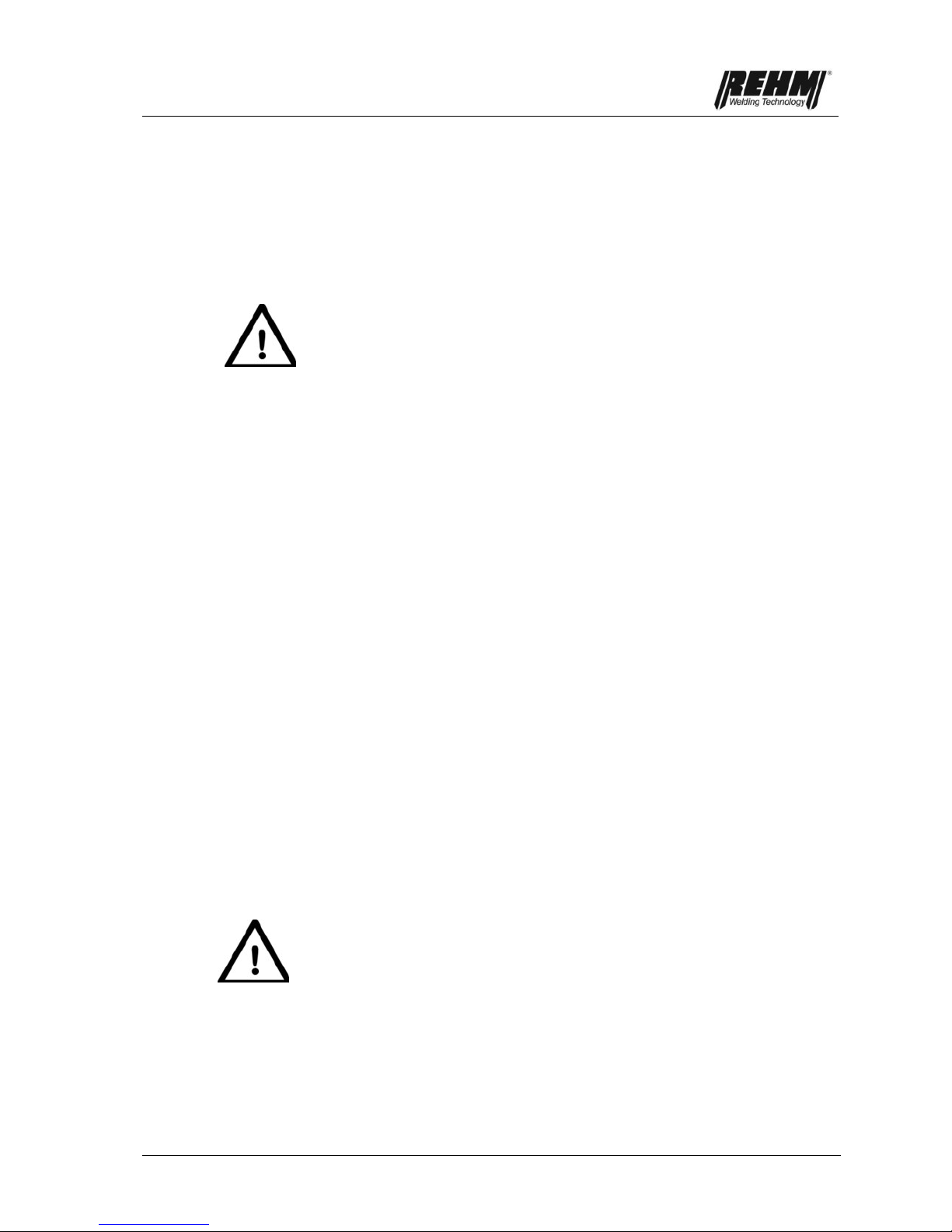
Putting into operation
61
5. Putting into operation
5.1 Safety notes
Read the operating instructions, in particular,
Chapter 2, Safety notes,
carefully before starting work on this current power source.
Warning!
REHM welding units may only be operated and maintained by persons who
have been educated and trained to operate and maintain welding units.
When welding, always wear protective clothing and ensure that other
people in the vicinity of the machine are not endangered by the UV
radiation of the arc.
5.2 Working under increased electrical danger (IEC
974, EN 60974-1, TRBS 2131 and BGR 500
chapter 2.26)
The REHM TIG welding units meet the requirements for working under
increased electrical danger in accordance with IEC 974, EN 60974-1, TRBS
2131 and BGR 500 chapter 2.26 (S).
For alternating current welding, a safety feature has been built in to the electronic
control. This ensures that when welding using alternating current, the arc is only
ever ignited with direct current and only when the welding current starts to flow
does the machine switch to alternating current. If the arc is suddenly broken
during welding, the machine automatically deactivates the HF and the welding
current. The machine then returns to the basic state.
You should ensure that when working under increased electrical risk, the power
source is not set up in this area. Observe the regulations EN 60974-1, TRBS
2131 and BGR 500 chapter 2.26.
5.3 Setting up the welding unit
Set the REHM welding unit in such a way that the welder has sufficient space in
front of the unit to control the setting elements and to operate it.
Secure the unit in such a way that it cannot roll away or fall.
Pay attention to the relevant accident regulations when transporting the unit.
Only use the transportation options and fixtures provided for by REHM when
transporting the unit.
Danger! Electrical voltage!
Do not use the welding unit outside in the rain!

Putting into operation
62
5.4 Connecting the welding unit
Connect the REHM welding current source in accordance with the valid VDE
regulations to the power supply network and ensure that you meet all the
regulations stipulated by the appropriate professional associations.
When connecting the unit, pay attention to the specifications regarding the supply
voltage and network fuses. Safety mechanisms and fuses must always be set out
for the specified current. The required specifications can be found on the power
label of your unit.
Always switch the unit off when it is not in use.
Screw the cylinder pressure regulator onto the cylinder and check the seal of the
connection. Always close the bottle valve after completely work. Observe the
regulations of the appropriate professional associations.
5.5 Cooling the welding unit
Set the REHM welding unit up in such a way that the air inlets and outlets are not
affected. The duty cycle of the power components indicated can be reached only
with adequate ventilation (see "Technical data"). Ensure that no sanding dust,
dust or any other metal items or foreign objects are able to enter the unit.
5.6 Guidelines for working with welding power
sources
Welding tasks may only be carried out by specialists or trained personnel familiar
with the technology and procedures. When welding, wear protective clothing and
ensure that other people in the vicinity of the machine are not endangered. After
completing welding, leave the unit switched on for a few minutes so that the fan
runs a little longer and removes some of the residual heat from the unit.
5.7 Connecting welding cables or torches
The REHM TIG welding units are fitted with quick-fit socket systems for
connecting earth cables and TIG torches or electrode cables. The connection is
made by inserting and turning to the right. The inert gas hose is connected a via
quick connector to welding unit. The torch button socket is fitted into the socket
that is built in.
Important!
In order to prevent unnecessary losses of energy during welding ensure that all
of the connections of the welding cables are tightened and well insulated.
5.8 Connecting external components
External components are connected via the standard 7-pin remote control socket
on the back of the INVERTIG.PRO digital. These include the Rehm accessories
that are described in chapter 4 (remote foot controller P1, water cooling devices
TIG-COOL 2000 and TIG-COOL CART 2000, automation interface). The
electrical connection is made via a serial CAN connection.

Putting into operation
63
Important!
When using this 7-pin remote control socket, please ensure that you comply with
the directives pertaining to the use of serial bus systems. Particularly the
electromagnetic compatibility (EMC) specifications. Always use the accessories
provided by REHM.
Please note that the length of the INVERTIG.PRO iSystem cable between the
first and last subscribers must not exceed 20m because of the design of the
serial connection.
In order to ensure that the external connection is always reliably initialised, first
switch on the power switch of the INVERTIG.PRO digital and then the switches
of the external devices.
Operation
64
6. Operation
6.1 Safety notes
Read the operating instructions, in particular,
Chapter 2, Safety notes,
carefully before starting work on this current power source.
Warning!
REHM welding units may only be operated and maintained by persons who
have been educated and trained to operate and maintain welding units.
Working with and maintaining electrical welding units always carries slight
dangers. People who are not familiar with units and installations of this type may
hurt themselves or others. For these reasons, the operators must be warned of
the following potential dangers and the safety mechanisms that are to be used to
prevent possible damages. Independently of this, the user of a welding unit must
also inform themselves of the safety regulations of that company prior to starting
work.
6.2 Electrical risks
Connection and maintenance work on welding units and accessories may only be
carried out in accordance with the valid VDE regulations and the regulations of the
appropriate professional associations.
Never touch metal parts under current with bare skin or wet clothing.
Always wear gloves and welding masks with the appropriate protection filters
when welding.
Ensure that all parts that you must touch during your work, for example,
clothing, work area, torch, electrode holder and welding unit, are always dry.
Never work in a wet environment.
Ensure good insulation by wearing dry gloves and rubber-soled shoes and
standing on an insulating surface, in particular when you are standing on a
metal surface or in areas with increased electrical danger.
Do not use worn or damaged welding cables. Ensure that the welding cables
are not overloaded. Only use equipment that is in good condition.
When taking a longer break from work switch the welding unit off.
Do not wind the welding cable about the housing parts and do not leave it
coiled up.
Never leave a switched on welding unit unattended.
6.3 Personal safety tips
The rays of the electrical arc and the hot metal can both lead to serious burns on
unprotected skin and eyes.
Only use welding masks with permitted protective filters, leather gloves and a
mask to protect your eyes and body from sparks and from the rays of the arc
(see TRBS 2131 and BGR 500 chapter 2.26). Also wear the same kind of
protective even if you are only supervising welding work.

Operation
65
Inform people standing by of the dangers of the arc rays and the hot metal
sparks and protect them using a shield that is not flammable.
Pressurised gas bottles also present a potential danger. Strictly observe the
safety regulations of the relevant professional authorities and the suppliers.
Ensure that inert gas bottles are not able to fall. Never transport inert gas
bottles without their protective caps.
6.4 Fire prevention
Hot slag and sparks can cause fires if they come into contact with flammable
materials, liquids or gases. Remove all flammable materials from the welding
area and ensure a fire extinguisher is on stand-by.
6.5 Ventilation
Work places must be set up, whilst taking account of procedures, materials and
conditions of use, in such a way that the air the user breathes is free from
unhealthy materials (see TRBS 2131 and BGR 500 chapter 2.26).
Ensure that the welding area is well ventilated either by natural means or by
technical ventilation systems.
Do not weld painted or solvent treated work pieces as these may give off
poisonous gases.
6.6 Checks before starting
The prerequisites that
the unit is set up correctly in accordance with Chapter 5, Putting into
operation
all connections (inert gas, torch connection) have been made in accordance
with Chapter 5, Putting into operation
the appropriate maintenance has been carried out in accordance with the
maintenance interval Chapter 8, Maintenance
the safety mechanisms and the components of the unit (in particular the torch
connector hoses) are checked by the operator and are functional.
the operator and other persons involved have put on the appropriate
protective clothing, and the working area has been shielded so that no
bystanders are at risk.
6.7 Connecting the earth cable
Warning!
Chapter 6.2 Electrical risks. Make sure that the welding current is not
able to flow through chains of lifting machinery, crane lines or other
current carrying parts.
Chapter 6.2 Electrical risks. Make sure that the earth cable is connected
to the work piece as close as possible to the welding area. Earth
connections affixed to points further apart reduce the effectiveness and
increase the risk of electrical shocks and stray current.

Operation
66
6.8 Practical notes
The practical user tips below represent just an overview of the wide range of
applications of REHM TIG welding units. For questions regarding specific
welding tasks, materials, inert gases or welding equipment, see the professional
literature or manufacturer recommendations.
When TIG welding you differentiate between materials, those that are welded
under direct current, and those welded under alternating current. Direct current
materials are non-alloyed, alloyed, highly alloyed steels, as well as copper,
nickel, titanium and their alloys. Alternating current is generally used for
aluminium and the associated alloys.
Various tungsten electrodes are offered and used for TIG welding. The
differences lie in the proportion and type of doping elements in tungsten
electrodes. The compositions are set out in DIN EN ISO 6848 (formerly EN
26848) and are generally made up of thorium oxide, ceroxide, zircon oxide or
lanthan oxide. The advantages of tungsten electrodes containing oxides are:
• better ignition characteristics
• more stable arc
• greater current resilience
• longer stand time
REHM supplies their torches with tungsten electrode WC 20 (grey) as standard.
The most frequently used electrode diameters and their resilience can be found
in the relevant technical literature. Remember that the values specified there are
calculated with machines that do not have the balance range of the REHM TIG
units. The guideline is that the current is too high for a given electrode if it drips
or has a broom-like structure. You can choose between lower current or, when
using alternating current, using a larger minus proportion in the balance setting.
When welding with direct current, the electrode is pointed.
The REHM TIG welding units can also use pointed electrodes for alternating
currents welding with the balance settings in the minus region. This has the
advantage that the arc is even more concentrated and effective. This also usually
increases the welding speed.
Remember when grinding the electrode, the grind direction should be along the
length of the electrode. To avoid risks, only use grinding units and extraction
systems suitable for the purpose.
Argon is usually used as inert gas for TIG welding. For some applications,
helium, argon/helium mixes, or argon/hydrogen mixes may also be used. With
the increase in helium, the arc ignition is more difficult and the application of heat
higher. The amount of inert gas required will depend on the electrode diameter,
gas nozzle size, welding current level and the movement of air at the place of
work. With a work piece thickness of 4 mm using argon as inert gas, the first
guideline is, for example, aluminium requires approximately 8 litres a minutes
and steel and chrome-nickel-steel 6 litres a minute. When using helium, the
required amount is considerably higher.
The standard lengths of the TIG torches are 4 m and 8 m. But longer torches
may also be connected to these machines. Depending on the task and current
level, the appropriate tungsten electrode, split pin and gas nozzle must be
selected. When using torches with two buttons, the two current regulators can be
used during welding to switch the current between two preset values.
Weldable materials
Tungsten
electrodes
Inert gases
TIG torches

Operation
67
Additional welding materials are added in stock form when welding manually.
The correct material for the basic material must be selected. But excellent results
can also be achieved if you just allow the welding bath of two pieces to come
together, for example, on corner seams.
When direct current welding, the minus pole is usually at the electrode. The
minus pole is the colder pole, this means that the current resilience and the stand
time of the tungsten electrode is considerably greater than when plus pole
welding.
When alternating current welding, the resilience of the electrode is heavily
influenced by the balance setting. The balance setting distributes the plus and
minus proportions of the welding current between the electrode and the work
piece. During the positive half wave, the aluminium oxide skin is destroyed and a
higher temperature occurs at the electrode. During the negative half wave, the
electrode cools down and the aluminium is heated. Since tearing the aluminium
oxide skin only need a short plus impulse, REHM TIG units can use a high minus
proportion.
This has many benefits:
1. the temperature load of the electrode is reduced
2. the electrode can be loaded with a higher current
3. the current range of the electrode increases
4. a pointed electrode can be used for welding
5. the arc is slimmer
6. the penetration is deeper
7. the heat influence zone of the weld is smaller
8. the welding speed increases
9. the application of heat to the work piece reduces
Practical values of the balance setting for alternating current welding are:
• with butt welds 60% to 70% minus proportion
• with hollow seam welds 70% to 80% minus proportion
see "Tungsten electrodes".
Welding with and
without additional
materials
Direct current
welding
Alternating current
welding

Operation
68
For contact-less ignition of the arc, the high-frequency ignition units are built as
standard in the REHM INVERTIG.PRO digital units. The high-frequency ionises
the gap between the tungsten electrode and the work piece in such a way that
the arc can jump across. A higher oxide proportion in the tungsten electrode or a
closer gap to the work piece have a positive effect on the ignition behaviour.
When direct and alternating current welding, the arc is able to be ignited by the
built-in program controller even without high-frequency. This is how it works:
The HF setting is set to "Off", the tungsten electrode is touched to the work
piece, then the torch button pressed and the electrode lifted from the work piece
by tipping the torch over the gas nozzle. Ignition of the arc without high-frequency
is of benefit when, for example, welding in hospitals or repairing electronically
controlled machines when a disruptions may be caused to controls as a result of
by high-frequency ignition units.
REHM TIG units are, thanks to their fast and precise regulation dynamics, ideal
current sources for electrode welding. The current level and polarity to be set is
specified by the electrode manufacturers. When welding basic electrodes, plus
pole welding is to be used.
More information can be found in the technical literature from
DVS-Verlag GmbH
Aachener Str. 172
40223 Düsseldorf
www.dvs-verlag.de
Ignition
with and withou
t
high-freqeuncy
(HF)
Welding stick
electrodes
Faults
69
7. Faults
7.1 Safety notes
Warning!
In the event of a fault occurring which may endanger persons, machinery
or the surrounding area, deactivate the unit immediately and ensure that it
cannot be reactivated.
Only restart the unit when the cause of the fault has been eliminated and
no further risk is posed to people, machinery and/or surrounding area,
Faults should only be eliminated by qualified personnel and all safety notes
should be observed.
The unit must be released for use by qualified personnel before being
restarted.
7.2 Table of faults
REHM control panel not working
No display on screen
Cause: Remedy:
No mains power supply (possibly mains fuse) Check mains voltages
Fault in power cable or plug Check.
Current rise time and current down slope time are at "0.0" and cannot be changed
Cause: Solution:
Foot remote control is attached Times are controlled by remote.
Remove remote control.
Current rise time and current down slope time
are not being met
Cause: Solution:
Start current set to 100 % Lower start current value
End crater current set to 100% Lower end crater current value
4-step cannot be set
Cause: Solution:
Foot remote control is attached Remove remote control.
Balance and frequency cannot be selected
Cause: Solution:
Polarity is not " " Can only be set in alternating current area

Faults
70
Unit has different parameters on start
than on switch off
Cause: Solution:
Values are only saved after Carry out welding
Welding procedure saved.
Inert gas is not flowing
Cause: Solution:
Bottle is empty or the gas hose has been bent. Check
Pressure reducer is defective. Check
Gas valve in the machine is defective. Contact service
Flat connect on the gas valve is loose. Check
Welding process "Electrode" Gas valve remains closed
Fans cannot be heard to be turning
Cause: Solution:
The fan level is adjusted to suit requirements, at low Check to see whether the fan switches
temperatures the fan will turn at lower revolutions to higher revolutions when put under more
or switches off. load.
Fan is defective. Contact service
No high voltage impulse
Cause: Solution:
HF ignition is set to off Switch on HF ignition
No inert gas available Check
Earth cable connected badly Check
Electrode is dirty Sharpen
No suitable electrode Change electrode
Gas pre-flow time too long Shorten gas pre-flow time, or wait
High frequency surge at torch Change torch
Connectors for torch and earth cable swapped Connect the correct way round
Welding current does not reach the specified value
or arc does not burn
Cause: Solution:
Earth cable connected badly. Check
Foot remote control attached and not Check
pressed.
Hand remote control attached Set current on remote
No inert gas or incorrect gas Check

Faults
71
Arc flickers and jumps
Cause: Solution:
Electrode and work piece do not reach Use thinner electrode
working temperature
Electrode is badly pointed Sharpen electrode.
No suitable electrode Change electrode
Arc is a strange colour
Cause: Solution:
No/too little/incorrect inert gas Check
Electrode is dirty Sharpen
Electrode burns off
Cause: Solution:
No inert gas Check
Current load too high Use thicker electrode
Proportion of Plus too high when welding Use the Balance to increase
with alternating current the proportion of Minus
Connectors for torch and earth cable swapped Connect the correct way round
MMA welding is set Set TIG welding
Unit is not pulsing
Cause: Solution:
Pulse is not activated Set T1 and/or T2 pulse times
Values for I1 and I2 are the same Change values
Arc breaks away on ignition
Cause: Solution:
Ignition energy has been set too low Set the ignition energy or use a thinner
electrode
Electrode is used or dirty Sharpen electrode again
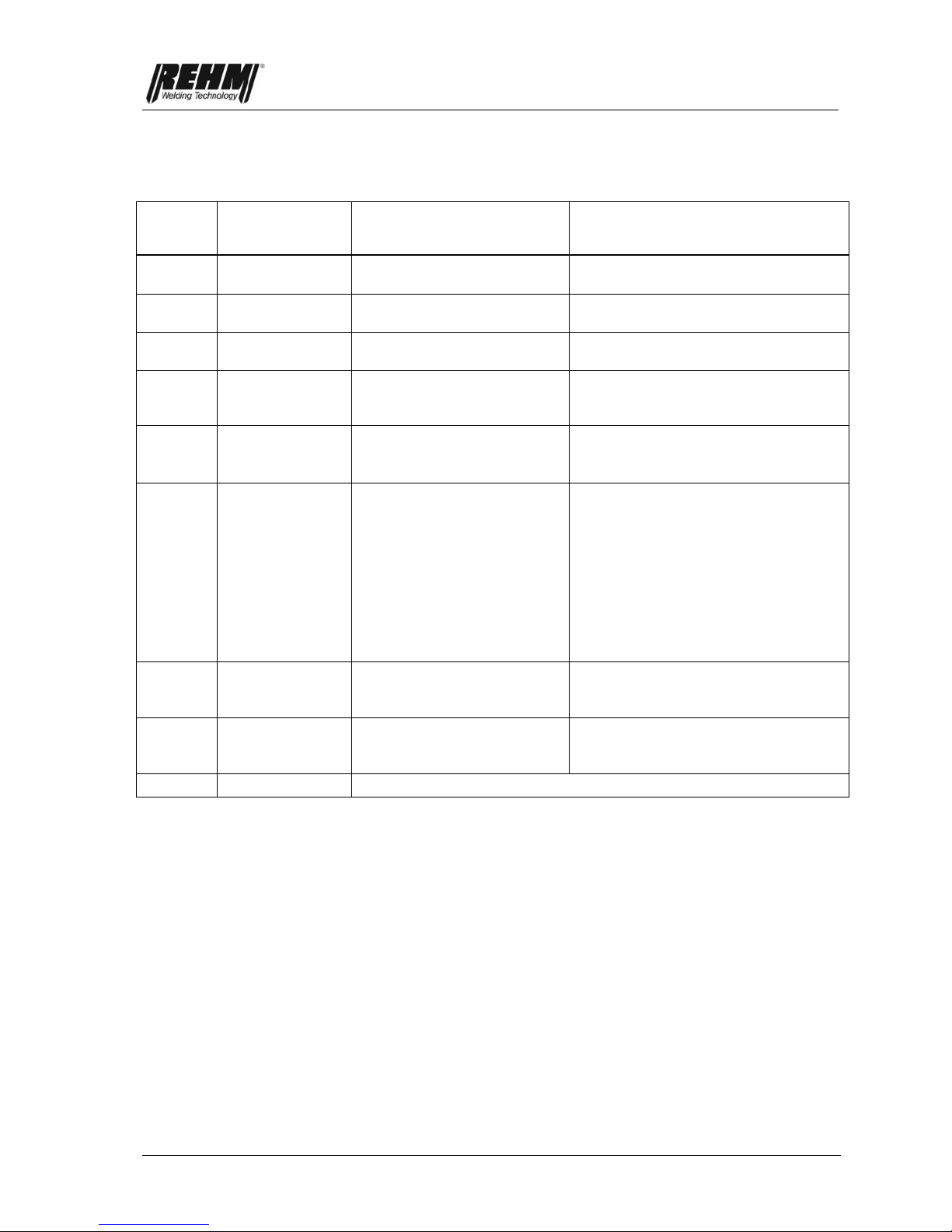
Faults
72
7.3 Error messages
Error
number
Error
Cause
Solution
1
Phase failure
At least one phase of main
supply voltage has failed
Check main fuse, cables and
connectors
2
Over voltage
Main supply has supplied
over voltage > 480 V
Check mains voltage
3
Under voltage
Main supply has supplied
under voltage < 320 V
Check mains voltage
20
Water-cooling
Welding with water-cooled
torch without water cooling
unit
Connect water-cooling unit
Replace torch (gas-cooled)
21
TIG torch in
electrode
operation
Electrode operation active
with a TIG torch connected
Remove TIG torch
Switch to TIG operation
30
Through flow
coolant
Through flow monitor
identifies too low a
throughput of coolant
Monitor blocked by dirt
Switch off power source immediately
Check whether the CAN connection
cable in plugged in
Check the level of the coolant
Check the connections of the water-
cooled torch
Lift the interruptions in the coolant
circulation
Bleed the coolant circulation system
Check pump
31
Water-cooling
Water-cooling unit is not
available (cable breach in
AUTO mode)
Check whether the CAN connection
cable in plugged in
Connect water-cooling unit
32
Over heated
coolant
Temperature of coolant >
65°C
Allow the water-cooling unit to cool
down
Refill coolant
> 51
Contact service
Analysis of causes can only be carried out by a service technician

Maintenance work
73
8. Maintenance work
8.1 Safety notes
Warning!
Repair and maintenance work may only be carried out by personnel who
have been trained by REHM. Contact your REHM representative. When
replacing parts, only use original REHM parts.
If maintenance or repair work is carried out on this unit by personnel who
have not been trained by REHM and thus are not authorised to carry out
the work, this will void your guarantee and warranty claims over REHM.
Before starting to clean the welding unit, it must be switched off and taken
from the power network!
Before starting maintenance work on the welding unit, it must be switched
off and taken from the power network and secured against accidental
reactivation.
Supply lines must be capped and switched without pressure.
The warning notes given in
Chapter 2 "Safety" must be taken into
account.
The welding unit and its components are to be maintained in accordance with the
specifications made in the operating and maintenance instructions.
Insufficient or incorrect maintenance or repairs can lead to disruptions in
operation. Regular maintenance of the unit is thus essential. No structural
changes or additions may be made to the unit.
8.2 Maintenance table
The maintenance intervals given are a recommendation made by REHM whilst
assuming normal circumstances (e.g. single-shift operation, in a clean and dry
environment). The exact intervals will be specified by your safety officer.
Task
Interval
Cleaning the inside of the unit
according to utilisation
conditions
Functional testing of safety mechanisms by
operating personnel
Daily
Observational check of the unit, with special
attention to the torch hoses
Daily

Maintenance work
74
Task
Interval
Check the functions of the error current
protection switch
Daily
(with flying objects)
Otherwise, monthly
Connection lines and torch hoses checked by
professionals, check should be logged in the
relevant log book
Check may need to be carried out more
often in order to meet local regulations.
Every six months
Entire welding unit checked by professionals,
check should be logged in the relevant log
book
Check may need to be carried out more
often in order to meet local regulations.
Once a year
8.3 Cleaning the inside of the unit
If the REHM welding unit is used in a dusty environment, then the inside of the
unit must be cleaned regularly by vacuuming or blasting.
The frequency of the cleaning process depends on the conditions under which it
is used. Use clean, dry air to clean the unit or a vacuum cleaner.
If maintenance or repair work is carried out on this unit by personnel who have
not been trained by REHM and thus are not authorised to carry out the work, this
will void your guarantee and warranty claims over REHM.
8.4 Correct disposal
Only applies to countries in the EU.
Do not put electrical tools in the household rubbish.
The European directive 2002/96/EG regarding the disposal of electronic an
electrical goods and the implementation of such in national law means that used
electrical tools must be collected separately and sent for environmentally-friendly
recycling.

Circuit diagrams
75
9. Circuit diagrams
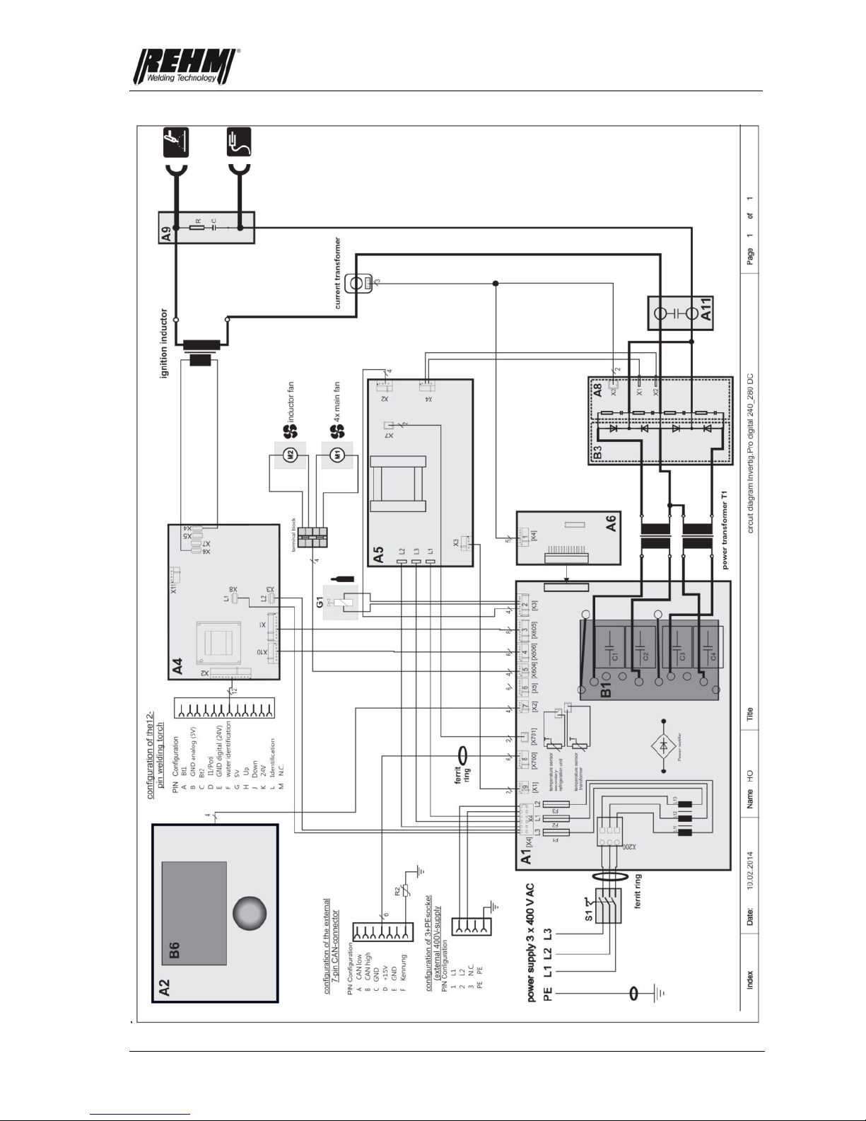
Circuit diagrams
76

Circuit diagrams
77

Circuit diagrams
78

Components
79
10. Components of the INVERTIG.PRO digital
units
10.1 List of components with REHM part numbers
No.
Description
240 DC
240
AC/DC
280 DC
280
AC/DC
350 DC
350
AC/DC
450 DC
450
AC/DC
1.
Cover
2101901
2101901
2101901
2101901
2101901
2101901
2101901
2101901
2.
Floor
2101900
2101900
2101900
2101900
2101900
2101900
2101900
2101900
3.
Side panel right
2101902
2101902
2101902
2101902
2101902
2101902
2101902
2101902
4.
Side panel left
2101903
2101903
2101903
2101903
2101903
2101903
2101903
2101903
5.
Handle
2600207
2600207
2600207
2600207
2600207
2600207
2600207
2600207
6.
Bar right
2600201
2600201
2600201
2600201
2600201
2600201
2600201
2600201
7.
Bar left
2600202
2600202
2600202
2600202
2600202
2600202
2600202
2600202
8.
Washer for incremental
sensor
2600215
2600215
2600215
2600215
2600215
2600215
2600215
2600215
9.
Front
2600200
2600200
2600200
2600200
2600200
2600200
2600200
2600200
10.
Air outlet
2600203
2600203
2600203
2600203
2600203
2600203
2600203
2600203
11.
Feed shaft for feet
2600210
2600210
2600210
2600210
2600210
2600210
2600210
2600210
12.
Rubber feet
3300005
3300005
3300005
3300005
3300005
3300005
3300005
3300005
13.
Screw
2900352
2900352
2900352
2900352
2900352
2900352
2900352
2900352
14.
Main board (A1)
6900570
6900570
6900570
6900570
6900574
6900574
6900574
6900574
15.
Control board (A6)
6900583
6900583
6900575
6900575
6900583
6900583
6900575
6900575
16.
IMS-PFC (B4)
- - - - 6900578
6900578
6900578
6900578
17.
IMS primary (B1)
6900576
6900576
6900576
6900576
6900577
6900577
6900577
6900577
18.
Rectifier
5300082
5300082
5300082
5300082
5300082
5300082
5300082
5300082
19.
Power supply (A5)
6900603
6900603
6900603
6900603
6900603
6900603
6900603
6900603
20.
Ignition device board (A4)
6900606
6900606
6900606
6900606
6900606
6900606
6900606
6900606
21.
Controller (A2)
6900561
6900561
6900561
6900561
6900561
6900561
6900561
6900561
22.
IMS rectifier (B3)
6900585
6900585
6900585
6900585
6900586
6900586
6900586
6900586
23.
Anti-interference board (A8)
6900580
6900580
6900580
6900580
6900580
6900580
6900580
6900580
24.
IMS board AC switch (B2)
-
6900595
-
6900595
-
6900597
-
6900597
25.
AC board controller (A10)
-
6900590
-
6900590
-
6900590
-
6900590
25.1
Ignition booster plate
(A11)
6900593
6900593
6900593
6900593
6900593
6900593
6900593
6900593
26.
Anti-interference board (A9)
6900602
6900602
6900602
6900602
6900602
6900602
6900602
6900602
27.
Performance transfer (T1)
4700375
4700375
4700375
4700375
4700376
4700376
4700376
4700376
28.
Ignition choke
4700379
4700379
4700379
4700379
4700379
4700379
4700379
4700379
29.
Current sensor
5300080
5300080
5300080
5300080
5300080
5300080
5300080
5300080
30.
Ferrite ring
4500045
4500045
4500045
4500045
4500045
4500045
4500045
4500045
31.
Ring core
4500044
4500044
4500044
4500044
4500044
4500044
4500044
4500044
32.
Fan for HF choke
4100054
4100054
4100054
4100054
4100054
4100054
4100054
4100054
33.
Fan
4100051
4100051
4100051
4100051
4100051
4100051
4100055
4100055
34.
Plastic rivet
3000036
3000036
3000036
3000036
3000036
3000036
3000036
3000036
35.
Power cable
3600137
3600137
3600137
3600137
3600139
3600139
3600139
3600139
36.
Cable connector
3700085
3700085
3700085
3700085
3700085
3700085
3700085
3700085
37.
Main switch (S1)
4200004
4200004
4200004
4200004
4200004
4200004
4200004
4200004
38.
Switch handle
4200156
4200156
4200156
4200156
4200156
4200156
4200156
4200156
39.
Installation socket
4300122
4300122
4300122
4300122
4300122
4300122
4300122
4300122
40.
Cable set
3600485
3600485
3600485
3600485
3600485
3600485
3600485
3600485
41.
One-handed coupling
3100186
3100186
3100186
3100186
3100186
3100186
3100186
3100186
42.
Magnetic valve (G1)
4200075
4200075
4200075
4200075
4200075
4200075
4200075
4200075
43.
Cable set for unit socket
3600487
3600487
3600487
3600487
3600487
3600487
3600487
3600487
44.
Connecting cable from
the PCB to CAN
INVERTIG PRO
3600488
3600488
3600488
3600488
3600488
3600488
3600488
3600488

Components
80
No.
Description
240 DC
240
AC/DC
280 DC
280
AC/DC
350 DC
350
AC/DC
450 DC
450
AC/DC
45.
Gas hose
2200100
2200100
2200100
2200100
2200100
2200100
2200100
2200100
46.
Fuse inset
6600042
6600042
6600042
6600042
6600042
6600042
6600042
6600042
47.
Incremental sensor
4200175
4200175
4200175
4200175
4200175
4200175
4200175
4200175
48.
Rotating button
2600214
2600214
2600214
2600214
2600214
2600214
2600214
2600214
49.
Washer for rotating
button
2600215
2600215
2600215
2600215
2600215
2600215
2600215
2600215
50.
Graphic sheet
7301602
7301607
7301604
7301608
7301605
7301609
7301606
7301610
51.
Resistor
5000258
5000258
5000258
5000258
5000258
5000258
5000258
5000258
52.
Anti-interference board AC
switch
6900592
6900592
6900592
6900592
53.
Graphical display (B6)
6900599
6900599
6900599
6900599
6900599
6900599
6900599
6900599
54.
Textile seal for display
3300140
3300140
3300140
3300140
3300140
3300140
3300140
3300140
55.
Pertinax holder display
3400227
3400227
3400227
3400227
3400227
3400227
3400227
3400227
56.
Replacement frame
spring
3000180
3000180
3000180
3000180
3000180
3000180
3000180
3000180
57.
Screen, incremental
encoder
2900367
2900367
2900367
2900367
2900367
2900367
2900367
2900367
58.
Incremental encoder nut
2900368
2900368
2900368
2900368
2900368
2900368
2900368
2900368
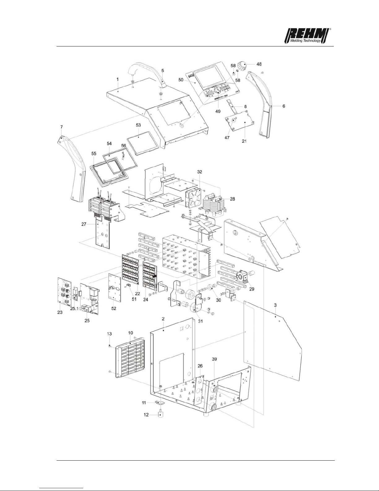
Components
81
Figure 53: Exploded view of an INVERTIG.PRO digital 240 DC – 450 AC/DC (left)

Components
82
Figure 54: Exploded view of an INVERTIG.PRO digital 240 DC – 450 AC/DC (right)

Technical data
83
11. Technical data
Type
240 AC/DC
240 DC
280 AC/DC
280 DC
350 AC/DC
350 DC
450 AC/DC
450 DC
Setting range
TIG
[A]
3 – 240
3 – 280
3 – 350
3 – 450
MMA
[A]
3 – 240
3 – 280
3 – 350
3 – 360
Duty cycle at I
max.
TIG
[%]
100
100
100
100
(10 min.) at 40℃
MMA
[%]
100
60
100
100
Welding current at 100 %
Duty cycle
TIG
[A]
240
280
350
450
MMA
[A]
240
260
350
360
Maximum power
consumption
[kVA]
9,3
11,9
16,3
16,5
Open circuit voltage
[V]
91
91
91
91
Effective current I1
Eff
[A]
13,5
13,4
22,5
24,0
Maximum effective
current I1
max
[A]
13,5
17,3
22,5
24,0
Mains voltage
3x400V
50Hz
3x400V
50Hz
3x400V
50Hz
3x400V
50Hz
Supply voltage tolerance
-15% / +10%
-15% / +10%
-15% / +10%
-15% / +10%
Fuse
[A]
16
16
32
32
Short-circuit performance, main supply
S
SC
[MVA]
3,3
4,2
5,7
5,8
Performance factor
0,96
0,96
0,96
0,96
Protection class
IP 23
IP 23
IP 23
IP 23
Apex voltage HF U
p
[kV]
12
12
12
12
Insulation class
B B B
B
Torch cooling type
Gas / Water
Gas / Water
Gas / Water
Gas / Water
Dimensions L/W/H
[mm]
520 x 360 x 460
520 x 360 x 460
520 x 360 x 460
520 x 360 x 460
Weight
AC/DC
[kg]
27
27
31.5
31.5
DC
[kg]
25
25
30.5
30.5
We reserve the right to make technical changes to reflect further development.
a)
Performance factor
=
describes the relationship of effective power to apparent power
b)
Protection class
=
Extent of protection offered by housing against penetration of solid foreign matter and
water (IP23 = protection against solid foreign matter > 12.5 mm and against splash
water)
c)
Insulation class
=
Class of the insulation materials used and their highest permitted constant
temperature (B = highest permitted constant temperature 130°)
d)
Short-circuit
performance, main
supply S
SC
=
minimum permitted short-circuit performance of the main supply system in
accordance with IEC 61000-3-12

Index
84
12. INDEX
A
Accessories ................................................................................................................................................................... 57
Accident prevention ....................................................................................................................................................... 11
Additional regulations ...................................................................................................................................................... 9
Alternating current welding ............................................................................................................................................ 67
Areas of use .................................................................................................................................................................. 11
Automaticfrequencysystem ........................................................................................................................................... 28
C
Changes to the unit ....................................................................................................................................................... 12
Cleaning the inside of the unit ....................................................................................................................................... 74
Connecting the earth cable ............................................................................................................................................ 65
Correct use ...................................................................................................................................................................... 9
D
Dilemmas ...................................................................................................................................................................... 34
Direct current welding .................................................................................................................................................... 67
DVS ............................................................................................................................................................................... 68
F
Faults ............................................................................................................................................................................. 69
G
Gap bridging .................................................................................................................................................................. 34
H
High voltage ignition ...................................................................................................................................................... 33
I
Ignition ........................................................................................................................................................................... 68
Increased electrical risk ................................................................................................................................................. 61
Index .......................................................................................................................................................................... 3, 84
Inert gases ..................................................................................................................................................................... 66
Inert gas consumption ................................................................................................................................................... 25
L
Lift-Arc ........................................................................................................................................................................... 34
M
Maintenance intervals .................................................................................................................................................... 73
Maintenance work ......................................................................................................................................................... 64
Maintenance work ......................................................................................................................................................... 73
Manufacturer ................................................................................................................................................................... 2
O
Operation
Checks before starting .............................................................................................................................................. 65

Index
85
P
Personnel qualifications ................................................................................................................................................. 12
Practical notes ............................................................................................................................................................... 66
Product identification
Machine identification ................................................................................................................................................. 2
Type number ............................................................................................................................................................... 2
Protection ...................................................................................................................................................................... 11
Pulses ............................................................................................................................................................................ 35
Purpose of the document .............................................................................................................................................. 12
Putting into operation ..................................................................................................................................................... 61
R
REHM control panel ...................................................................................................................................................... 13
Remote control units ...................................................................................................................................................... 57
Residual dangers ........................................................................................................................................................... 11
S
Safety
Dangers of non-observation ...................................................................................................................................... 11
Safety notes......................................................................................................................................................... 6, 10, 11
Safety symbols ................................................................................................................................................................ 6
Setting up ...................................................................................................................................................................... 61
Stick electrodes ............................................................................................................................................................. 68
Storing the instructions .................................................................................................................................................. 12
Symbols ........................................................................................................................................................................... 9
T
Table of faults ................................................................................................................................................................ 69
Technical data ............................................................................................................................................................... 83
Typographic symbols ....................................................................................................................................................... 9
W
Warning symbols on the unit ......................................................................................................................................... 10
WIG torches ................................................................................................................................................................... 66
WIG welding procedure ................................................................................................................................................... 8
Wolfram electrode ......................................................................................................................................................... 66

86
EC Declaration of Conformity
We hereby confirm that the following products
TIG inert gas welding units
INVERTIG.PRO digital 240 DC, 240 AC/DC
INVERTIG.POR digital 280 DC, 280 AC/DC
INVERTIG.PRO digital 350 DC, 350 AC/DC
INVERTIG.PRO digital 450 DC, 450 AC/DC
meet all the major protection requirements laid down in the Council Directive 2004/108/EEC on the
approximation of the laws of the member states relating to electromagnetic compatibility and in
the Directive 2006/95/EEC relating to electrical equipment designed for use within certain voltage
limits
The above products conform to the regulations in this Directive and meet the safety requirements for
equipment used for arc welding in accordance with the following product standards.
EN 60 974-1: 2006-07
Arc welding equipment – Part 1: Welding power sources
EN 60 974-3: 2004-04
Arc welding equipment – Part 3: Arc ignition and stabilisation equipment
EN 60974-10: 2004-01
Arc welding equipment – Part 10: Electromagnetic compatibility (EMC) requirements
In accordance with the EU: Directive 2006/42/EG Article 1, Section. 2, the above products come
exclusively under the scope of Directive 2006/95/EWG relating to electrical equipment designed for use
within certain voltage limits.
This declaration is made on behalf of the manufacturer:
REHM GmbH u. Co KG Schweißtechnik
Ottostr. 2
73066 Uhingen, Germany
Uhingen, 25.06.2015
Declaration made by
R. Stumpp
Managing Director


REHM – Setting the pace in welding and cutting
The REHM range
REHM MIG/MAG inert gas welding units
SYNERGIC.PRO² gas- and water-cooled to 450 A
SYNERGIC.PRO² water-cooled 500 A to 600 A
MEGA.ARC stepless regulation to 450 A
RP REHM Professional to 560 A
PANTHER 202 PULS pulse welding unit with 200 A
MEGA.PULS FOCUS pulse welding units to 500 A
REHM TIG inert gas welding units
TIGER, portable 100 KHz inverter
INVERTIG.PRO TIG welding unit
INVERTIG.PRO digital TIG welding unit
REHM MMA inverter technology
TIGER and BOOSTER.PRO 100 KHz electrode inverter
REHM plasma cutting units
Welding accessories and additional materials
Welding smoke extraction fans
Welding rotary tables and positioners
Technical welding consultation
Torch repair
Machine Service
Please contact your local distributor:
REHM WELDING TECHNOLOGY –
German Engineering and Production at its best
Development, construction and production – all under one
roof – in our factory in Uhingen. Thanks to this central
organisation and our forward-thinking policies, new
discoveries can be rapidly incorporated into our production.
The wishes and requirements of our customers form the
basis for our innovative product development. A multitude of
patents and awards represent the precision and quality of
our products. Customer proximity and competence are the
principles which take highest priority in our consultation,
training and service.
WEEE-Reg.-Nr. DE 42214869
Stand 06/15 · Artikel-Nr. 730 0143
 Loading...