


BOOSTER 140
BETRIEBSANLEITUNG
OPERATING INSTRUCTIONS
INSTRUCTIONS DE SERVICE
INSTRUCCIONES DE SERVICIO
ISTRUZIONI PER I´USO
GEBRUIKSAANWIJZING
D
GB
F
E
I
NL

2
Produktidentifikation
Schweißinverter
Artikelnummer
BOOSTER 140 150 3140
BOOSTER 140 SET 150 3141
Rehm GmbH u. Co. KG
Ottostr. 2
D-73066 Uhingen
Telefon: 07161/3007-0
Telefax: 07161/3007-20
e-mail: rehm@rehm-online.de
Internet: http://www.rehm-online.de
Dok.-Nr.: 730 1220
Ausgabedatum: 07:07
© Rehm GmbH u Co. KG, Uhingen, Germany 2004
Der Inhalt dieser Beschreibung ist alleiniges Eigentum der Firma
Rehm GmbH u. Co. KG
Weitergabe sowie Vervielfältigung dieses Dokuments, Verwertung und
Mitteilung seines Inhalts sind verboten, soweit nicht ausdrücklich gestattet.
Zuwiderhandlungen verpflichten zu Schadenersatz. Alle Rechte für den Fall
der Patent-, Gebrauchsmuster- oder Geschmacksmustereintragung
vorbehalten.
Eine Fertigung anhand dieser Unterlagen ist nicht zulässig.
Änderungen vorbehalten.
Bezeichnung
Typ

3
D
1 Allgemeine Beschreibung
Sehr geehrter Kunde,
Sie haben einen REHM - Schweißinverter und damit ein deutsches Markengerät erworben.
Wir danken Ihnen für das Vertrauen, das Sie in unsere Qualitätsprodukte setzen.
Der BOOSTER 140 ist ein professionelles Schweißgerät für das Elektroden-Schweißen aller
handelsüblichen Elektroden (Elektroden-Schweißen entspricht Lichtbogen-Hand-Schweißen
nach DIN1910). Die digitale Prozessorsteuerung und das hochdynamische Leistungsteil mit
seiner Taktfrequenz von 100 kHz bieten Ihnen beste Schweißeigenschaften. Sie brauchen
nur noch den richtigen Schweißstrom zu wählen. Das geringe Gewicht von nur 4,9 kg und
die ausgesprochen kompakten Abmessungen sorgen für eine einfache Handhabung.
Zusammen mit dem robusten Stahl-Gehäuse wird der BOOSTER 140 so zum idealen
Begleiter in der Werkstatt und für den harten Außeneinsatz auf der Baustelle.
Technische Daten:
- 140 A maximaler Ausgangsstrom bei einer Einschaltdauer von 40% (20°C)
- 110 A Ausgangstrom bei einer Einschaltdauer von 100% (20°C)
- hohe Leerlaufspannung von 91V
- HotStart + Arc Force
- kontinuierliche elektronische Netzspannungsüberwachung
- Anti-Stick-Funktion – kein Ausglühen der Elektrode beim versehentlichen Festkleben
- Schutzklasse IP23: Einsatz auch bei ungünstigen Umgebungsbedingungen
Der BOOSTER 140 ist universell für alle Schweißaufgaben an nichtrostenden Stählen, hochund niedriglegierten Stählen sowie an Buntmetallen einsetzbar und so der ideale Partner für
alle Fälle.

4
2 Folgende Sicherheitshinweise sind zu beachten
Es ist trockene Schutzkleidung zu tragen sowie Augen und Gesicht sind mit Schweißschild
zu schützen (siehe BGR 500). Das Gerät ist an geerdeten Steckdosen und mit Netzkabeln
mit ordnungsgemäß ange- schlossenem Schutzleiter zu betreiben.
Das Gerät darf nur durch ausgebildetes Fachpersonal gewartet werden. Bei Problemen steht
Ihnen der REHM-Kundenservice unter der Tel.-Nr. 07161/3007-85 zur Verfügung.
Beim Betrieb dieses Gerätes ist die Unfallverhütungsvorschrift Schweißen, Schneiden und
verwandte Verfahren (BGR 500) zu berücksichtigen. Die wesentlichen Gefahren sind:
Brand und Explosion
Schadstoffe (Gase, Dämpfe, Rauch / Stäube)
optische Strahlung
elektrische Gefährdung
Handhabungsfehler
Die BOOSTER-Schweißanlagen sind gemäß EN 60974-1 Lichtbogenschweißeinrichtungen Schweißstromquellen für Überspannungskategorie III und Verschmutzungsgrad 3 und
gemäß EN 60974-10 Lichtbogenschweißeinrichtungen - elektromagnetische Verträglichkeit
(EMV) ausgelegt und dürfen nur mit Netzversorgungssystemen verwendwet werden, die ein
Dreiphasen-Vier-Draht-Sytem mit geerdetem Neutralleiter sind.
Die Geräte sind für das Schweißen von Elektroden vorgesehen. Sie dürfen nur von
Personen, die in der Anwendung und Wartung von Schweißgeräten ausgebildet und
geschult sind, betrieben werden.
Das Gerät ist gemäß EN 60974-10 für Gruppe 2 Klasse A ausgelegt und eignet sich für den
Einsatz in allen Bereichen, außer dem Wohnbereich und solchen Betrieben, die direkt an ein
Niederspannungsnetz angeschlossen sind, das (auch) Wohngebäude versorgt.
3 Funktionsbeschreibung
3.1 Das REHM-Bedienfeld
3.1.1 Übersicht
Die Bedienung des Booster 140 erfolgt über das in Bild 3.1 dargestellte REHM- Bedienfeld.
A
140
120
100
8060
40
20
5
7301210
1
2
Bild 3.1 Bedienfeld BOOSTER 140
Das Bedienfeld ist in folgende Bereiche unterteilt:
c Kontrollleuchten für Betrieb und Übertemperatur
d Drehknopf für die Schweißstromvorwahl

5
D
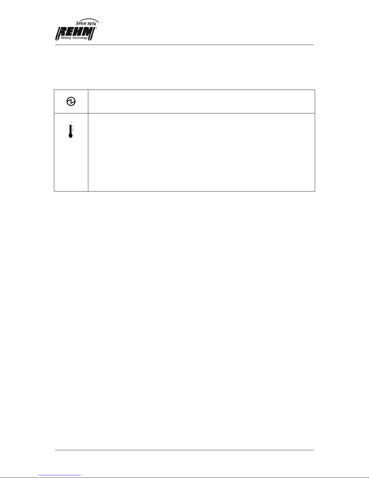
3.1.2 Symbole und deren Bedeutung
Die Symbole auf dem Bedienfeld haben folgende Bedeutungen:
Leerlaufspannung liegt am Brenner oder Elektrodenhalter an.
Temperaturanzeige.
Die Leuchtdiode (gelb) leuchtet bei Überschreitung der maximal zulässigen
Gerätetemperatur. Solange diese Leuchtdiode leuchtet, ist der
Ausgangsstrom abgeschaltet. Nach Abkühlung des Gerätes erlischt die
Leuchtdiode und es kann automatisch wieder geschweißt werden.
Bei blinkender Anzeige wurde interne Überwachung ausgelöst. Durch Aus- und
Einschalten am Netzschalter wird das
Gerät wieder einsatzbereit. Bitte den
REHM-Kunden-Sevice (RKS) darüber informieren.
3.2 Elektrodenschweißen
Das Gerät eignet sich zum Schweißen aller handelsüblichen Elektroden, wobei der maximale
Strom 140 A beträgt. Mit diesem Strom können handelsübliche Elektroden bis zu 3,25 mm
Durchmesser verschweißt werden.
Die Polung und Stromeinstellung für die einzelnen Elektroden können Sie aus den
Herstellerunterlagen der Elektroden entnehmen. Der Elektrodenhalter wird an der
Schweißstrombuchse eingesteckt, welche die für die Elektrode angegebene Polarität hat
(siehe Kapitel 3.4 und 3.5).
Sie brauchen lediglich den für Ihre Schweißaufgabe und für die dafür gewählte Elektrode den
passenden Schweißstrom und die richtige Polarität zu wählen. Den Rest erledigt der Booster
140 für Sie. Folgende Funktionen sorgen automatisch für gute Schweißarbeiten:
3.2.1 Hot Start
Beim Beginn der Schweißarbeit liefert der Booster 140 kurzfristig einen höheren Strom als
der eingestellte Schweißstrom (maximal 140A). Dies sorgt für eine gute Zündeigenschaft und
einen schnellen stabilen Lichtbogen.
3.2.2 Arc Force
Während der Schweißarbeit überwacht der Booster 140 den Schweißstrom und die
Schweißspannung. Erkennt der Booster 140, dass ein Tropfenübergang im Kurzschluss
stattfindet, so liefert er kurzfristig einen höheren Strom als der eingestellte Schweißstrom
(maximal 140A) um diesen Kurzschluss schnell zu lösen. Dadurch verhindert der Booster
140 Aussetzer oder Festkleben der Elektrode beim Schweißen.

6
3.2.3 Anti-Stick-Funktion
Entsteht beim Elektrodenschweißen ein permanenter Kurzschluss, so setzt nach ca. 1,0 s
die Anti-Stick-Funktion ein, die den Strom auf ca. 35 A begrenzt. Dadurch wird das
Ausglühen der Elektrode verhindert und der permanente Kurzschluss kann durch Abziehen
leicht gelöst werden.
3.3 Kennzeichnung „+“ auf der Schweißstrombuchse
Das „+“ - Zeichen kennzeichnet den positiven Pol der Schweißstromquelle (linke
Schweißstrombuchse).
3.4 Kennzeichnung „-“ auf der Schweißstrombuchse
Das „-“ - Zeichen kennzeichnet den negativen Pol der Schweißstromquelle (rechte
Schweißstrombuchse).
4 Netzanschluss
Das Schweißgerät ist mit einem Schutzkontaktstecker versehen. Der Betrieb des Gerätes
erfolgt an Sicherungen oder Leitungsschutzschaltern mit einem Nennstrom von 16A. Der
Betriebszustand EIN wird durch das Leuchten des an der Rückseite eingebauten
Netzschalters angezeigt. Der Booster 140 überwacht permanent die Netzspannung. Sollten
während des Betriebs zu hohe (über 260V~) oder zu niedrige Werte (unter 150V~) ermittelt
werden, schaltet sich das Gerät selbständig ab und geht in eine Schutzfunktion. Durch Ausund Einschalten kann bei richtiger Netzspannung weiter gearbeitet werden.
5 Aufstellung
Bei der Aufstellung der Geräte ist zu beachten, dass die Lüftungsschlitze nicht verdeckt
werden und dass die Umgebung der Schutzklasse IP23 entspricht.
6 Anwendungsbeschränkungen
Das Gerät kann bei allen Umgebungsbedingungen eingesetzt werden, die der Schutzklasse
IP23 oder kleiner entsprechen. Für Schweißungen in bestimmten Umgebungen (z.B.
Stallungen) werden besondere Anforderungen an die Schutzklasse der Schweißgeräte
gestellt. Die Verwendungsmöglichkeit des Gerätes in einer solchen Umgebung ist im
einzelnen zu überprüfen. Das Gerät ist nicht für den Einsatz im Mehrschichtbetrieb
vorgesehen.

7
D
7 Wartung
Das Gerät ist wartungsfrei, wobei jedoch der Zustand der elektrischen Anschlussleitungen
regelmäßig überprüft werden muss.
7.1 Ordnungsgemäße Entsorgung
Nur für EU-Länder.
Werfen Sie Elektrowerkzeuge nicht in den Hausmüll!
Gemäss Europäischer Richtlinie 2002/96/EG über Elektro- und ElektronikAltgeräte und Umsetzung in nationales Recht müssen verbrauchte
Elektrowerkzeuge getrennt gesammelt und einer umweltgerechten
Wiederverwertung zugeführt werden.
8 Technische Daten Booster 140
Einstellbereich [A] 5 - 140
Einschaltdauer (ED) bei I
max.
(10 min) bei 20°C [ bei 40°C] [%] 40 [30]
Schweißstrom bei 100 % ED bei 20°C [ bei 40°C] [A] 110 [95]
Schweißstrom bei 60 % ED bei 20°C [ bei 40°C] [A] 125 [110]
Leistungsaufnahme bei I
max.
[kVA] 6,2
Netzspannung 230V/50Hz
Absicherung [A] 16
Leistungsfaktor
Cos
ϕ
0,7
Schutzklasse IP 23
Abmessungen L/B/H [mm] 310/125/182
Gewicht [kg] 4,9

8
EG-Konformitätserklärung
Für folgend bezeichnete Erzeugnisse
BOOSTER 140
wird hiermit bestätigt, dass sie den wesentlichen Schutzanforderungen entsprechen, die in der
Richtlinie 2004/108/EG (EMV-Richtlinie) des Rates zur Angleichung der Rechtsvorschriften der
Mitgliedsstaaten über die elektromagnetische Verträglichkeit und in der Richtlinie 2006/95/EG
betreffend elektrischer Betriebsmittel zur Verwendung innerhalb bestimmter Spannungsgrenzen
festgelegt sind.
Die oben genannten Erzeugnisse stimmen mit den Vorschriften dieser Richtlinie überein und
entsprechen den Sicherheitsanforderungen für Einrichtungen zum Lichtbogenschweißen gemäß
folgenden Produkt Normen:
EN 60 974-1: 2006-07
Lichtbogenschweißeinrichtungen – Teil 1: Schweißstromquellen
EN 60 974-3: 2004-04
Lichtbogenschweißeinrichtungen – Teil 3: Lichtbogenzünd- und stabilisierungseinrichtungen
EN 60974-10: 2004-01
Lichtbogenschweißeinrichtungen – Teil 10: Elektromagnetische Verträglichkeit (EMV) Anforderungen
Gemäß EG. Richtlinie 89/392/EWG Artikel 1, Abs. 5 fallen o.g. Erzeugnisse ausschließlich in den
Anwendungsbereich der Richtlinie 2006/95/EG betreffend elektrischer Betriebsmittel zur Verwendung
innerhalb bestimmter Spannungsgrenzen.
Diese Erklärung wird verantwortlich für den Hersteller:
REHM GmbH u. Co. KG Schweißtechnik
Ottostr. 2
73066 Uhingen
Uhingen, den 17. Juli 2007
abgegeben durch R. Stumpp
Geschäftsführer

9
GB
Product Identification
Description Inverter
Article number
Type BOOSTER 140 150 3140
BOOSTER 140 SET 150 3141
Manufacturer REHM GmbH u. Co. KG
Otto Straße 2
D-73066 Uhingen
Telephone No.: 0049 (07161) 3007-0
Telefax No.: 0049 (07161) 3007-20
E-mail: rehm@rehm-online.de
Internet: http://www.rehm-online.de
Document Number. 730 1220
Date of Issue. 07:07
© REHM GmbH u. Co. KG, Uhingen, Germany 2004
The contents of this document is the exclusive property of the REHM GmbH
u. Co. KG
The transfer of this information to a third party or the copying of this
document, using the contents other than for the purpose intended is strictly
forbidden, unless otherwise agreed to in writing by the company. Failure to
comply with this condition in full will result in legal action against the person
or company committing the offence. All rights referring to Patents whether
actual or applied for, are reserved.
Using this information for the purposes of production is expressly forbidden.
We reserve the right to alter the contents of this document without prior
notice.

10
1 General Description
Dear customer,
You have purchased a REHM welding inverter, a brand-name German product. We would
like to thank you for the confidence you have placed in our high quality products.
The BOOSTER 140 is a professional welding unit for electrode welding of all commercial
electrodes (electrode welding corresponds to manual arc welding in accordance with DIN
1910). The digital processor control and the highly dynamic power component with its cycle
frequency of 100 kHz offer you ideal welding performance. You only need to select the right
welding current. The low weight of just 4.9 kg and the extremely compact dimensions ensure
easy handling. Together with the robust steel housing of the BOOSTER 140, these features
make it the ideal companion in the workshop and for arduous outdoor work on building sites.
Technical Data:
- 140 A maximum output current with a duty cycle of 40% (20°C)
- 110 A output current with a duty cycle of 100% (20°C)
- high no-load voltage of 91V
- Hot Start + Arc Force
- continuous electronic monitoring of power supply voltage
- Anti-Stick function – prevents electrode burnout in the event of accidental sticking
- Protection Class IP23: for use even in difficult ambient conditions
The BOOSTER 140 is designed for all types of welding work on stainless, alloy and nonalloyed steels and non-ferrous metals, making it the ideal partner for all types of work.

11
GB
2 The following safety precautions must be taken
Dry protective clothing must be worn. The eyes and face must be protected by welding
goggles (see German BGR 500 regulations).
The unit must be operated using earthed power sockets and mains cables with properly
connected earth conductors.
Accident Prevention Regulation "Welding, Cutting and Related Processes" (BGR 500) must
be observed during the operation of this unit. The main hazards are:
fire and explosion
harmful substances (gases, fumes, smoke / dust)
optical radiation
electrical hazards
handling errors
BOOSTER welding equipment is designed according to EN 60974-1 Arc welding equipment Welding power sources for overvoltage category III and pollution degree 3 and according to
EN 60974-10 Arc welding equipment, Electromagnetic compatibility (EMC) and may only be
used with mains supply systems, which are three phase four wire systems with earthed
neutral conductors.
The units are intended for the welding of electrodes. They may only be operated by people
who have been trained and are qualified in the use and maintenance of welding equipment.
The unit is designed in accordance with EN 60974-10 for Group 2 Class A and is suitable for
use in all areas, with the exception of living areas and premises directly connected to a low
voltage network which also supplies residential buildings.
3 Function description
3.1 The REHM control panel
3.1.1 Overview
The Booster 140 is operated using the REHM control panel shown in Fig. 3.1
A
140
120
100
8060
40
20
5
7301210
1
2
Fig. 3.1 BOOSTER 140 control panel
The control panel is divided into the following areas:
c Control lamps for overheating and operation
d Welding current control knob
12
3.1.2 Symbols and their meanings
The symbols on the control panel have the following meanings:
No-load voltage is applied to the torch or the electrode holder.
Temperature indicator.
The yellow LED lights up when the maximum permitted temperature of the unit
is exceeded. As long as this LED is on, the output current is switched off. After
the unit has cooled down, the LED goes out and welding can be restarted
automatically.
If this symbol flashes, the internal monitoring system has tripped. Switch the
mains switch off and back on to reset the unit. Please contact the REHM
Customer Service Department.
3.2 Electrode welding
The unit is suitable for use with all the usual types of electrode, the maximum current being
140 A. This current can be used to weld the usual types of electrode up to a diameter of 3.25
mm.
For the polarity and current settings for individual electrodes, please refer to the electrode
manufacturer's instructions. The electrode holder is plugged in at the welding current socket
which has the polarity specified for the electrode (see chapters 3.4 and 3.5).
You only need to select the appropriate welding current for your welding application and for
the electrode selected for this purpose, and to select the right polarity. The rest is handled for
you by the Booster 140. The following functions automatically ensure good welding results:
3.2.1 Hot Start
When the welding work begins, the Booster 140 supplies for a short time a higher current
than the welding current selected (max. 140A). This ensures good ignition and a steady arc
very quickly.
3.2.2 Arc Force
During the welding work, the Booster 140 monitors the welding current and the welding
voltage. If the Booster 140 detects that a droplet transfer takes place in a short-circuit, it
supplies for a short time a higher current than the welding current selected (max. 140A) in
order to quickly eliminate this short-circuit. As a result, the Booster 140 prevents failure or
sticking of the electrode during welding.

13
GB
3.2.3 Anti-Stick function
If there is a permanent short circuit during electrode welding, the Anti-Stick function is
activated after approx. 1.0 s, limiting the current to approx. 35 A. This prevents the electrode
from burning out, and the operator can easily interrupt the short circuit by removing the
electrode from the workpiece.
3.3 "+" marking on the welding current socket
The "+" sign indicates the positive pole of the welding current source (left-hand welding
current socket)
3.4 "-" marking on the welding current socket
The "-" sign indicates the negative pole of the welding current source (right-hand welding
current socket).
4 Mains connection
The welding unit is fitted with a protective contact plug. The unit is operated with fuses or
circuit breakers with a rated current of 16A. When the unit is switched ON, the main switch at
the back of the unit is lit up. The Booster 140 permanently monitors the power supply
voltage. If the values ascertained during operation are too high (above 260V~) or too low
(below 150V~), the unit switches itself off and reverts to a safety function. When the power
supply voltage is correct, operation can be resumed by switching the unit off and back on.
5 Installation
Care should be taken during installation of the unit to ensure that the ventilation slots are not
covered and that the installation site is suitable for Protection Class IP23.
6 Application limitations
The unit can be used in any environmental conditions corresponding to Protection Class
IP23 or lower. For welding in certain locations (e.g. stables), the Protection Class of the
welding units has to meet special requirements. The possibility of using the unit in such an
environment should be checked for each individual case. The unit is not intended to be used
for more than one shift per day.
7 Maintenance
The unit does not require maintenance. However, the condition of the electrical cables must
be checked at regular intervals

14
7.1 Proper waste disposal
Only for EU countries.
Do not dispose of electric tools together with household waste material.
In observance of European Directive 2002/96/EC on waste electrical and
electronic equipment and its implementation in accordance with national
law, electric tools that have reached the end of their life must be collected
separately and returned to an environmentally compatible recycling facility
.
8 Technical Data Booster 140
Setting range [A] 5 - 140
Duty cycle at I
max.
(10 min) at 20°C [ at 40°C] [%] 40 [30]
Welding current at 100 % duty cycle at 20°C [ at 40°C] [A] 110 [95]
Welding current at 60 % duty cycle at 20°C [ at 40°C] [A] 125 [110]
Power consumption at I
max.
[kVA] 6.2
Power supply voltage 230V/50Hz
Fusing [A] 16
Power factor
Cos ϕ
0,7
Protection class IP 23
Dimensions L/W/H [mm] 310/125/182
Weight [kg] 4.9

15
GB
EC Declaration of Conformity
We hereby confirm that the following products
Booster 140
meet all the major protection requirements laid down in the Council Directive 2004/108/EC (EMC
directive) on the approximation of the laws of the Member States relating to electromagnetic
compatibility and stipulated in the Directive 2006/95/EC relating to electrical equipment designed for
use within certain voltage limits.
The aforementioned products comply with the provisions of this Directive and meet the safety
requirements applicable to equipment for arc welding in accordance with the following product
standards:
EN 60 974-1: 2006-07
Arc welding equipment – Part 1: Welding power sources
EN 60 974-3: 2004-04
Arc welding equipment – Part 3: Arc striking and stabilizing devices
EN 60974-10: 2004-01
Arc welding equipment – Part 10: Electromagnetic compatibility (EMC) requirements
According to EC Directive 89/392/EEC Article 1, para. 5, the above products come exclusively within
the scope of Directive 2006/95/EC relating to electrical equipment designed for use within certain
voltage limits.
This declaration is made on behalf of the manufacturer:
REHM GmbH u. Co. KG Schweißtechnik
Ottostr. 2
73066 Uhingen Germany
Uhingen, 17
TH
July 2007
Declaration made by
R. Stumpp
Managing Director

16
Identification du produit
Désignation inverter primaire
référence REHM
Type BOOSTER 140 150 3140
BOOSTER 140 SET 150 3141
Fabricant REHM GmbH u. Co . KG
Otto Straße 2
D-73066 Uhingen
Téléphone: 0049 (07161) 3007-0
Télécopie: 0049 (07161) 3007-20
Courriel: rehm@rehm-online-de
Internet: http://www.rehm-online.de
Doc. n°: 730 1220
Date d’édition: 12.05
© REHM GmbH u. Co. KG, Uhingen, Alemagne 2004
Le contenu de la présente description est la propriété exclusive de la société
Rehm GmbH u. Co. KG
La transmission ainsi que la reproduction du présent document, l’exploitation
et la communication de son contenu sont interdites sauf autorisation
explicite.
Toute transgression entraîne l’obligation de réparer le dommage. Tous
droits réservés en cas de dépôt de brevet, de modèle d’utilité ou de dessin.
Une fabrication à partir de ces documents est interdite.
Sous réserve de modifications.

17
F
1 Description générale
Cher Client,
Vous avez fait l’acquisition d’un poste de soudage type inverseur REHM et donc d’un
appareil de marque allemand. Nous vous remercions de la confiance que vous placez dans
nos produits de qualité.
Le BOOSTER 140 est un poste destiné au soudage professionnel avec toutes les électrodes
du commerce (soudage avec électrodes conformément au soudage manuel à l’arc selon DIN
1910). La commande numérique à processeur et l’unité de puissance hautement dynamique
avec sa fréquence d’horloge de 100 kHz vous offrent les meilleures caractéristiques de
soudage. Il vous suffit de sélectionner le courant de soudage approprié. Le faible poids de
seulement 4,9 kg et les dimensions extrêmement compactes permettent un maniement aisé.
Avec son habillage robuste en acier, le BOOSTER 140 est ainsi l’assistant idéal dans l’atelier
et dans les durs travaux de chantier à l’extérieur.
Caractéristiques techniques :
- Courant de sortie maximal de 140 A pour un facteur de marche de 40 % (20 °C)
- Courant de sortie de 110 A pour un facteur de marche de 100 % (20 °C)
- Tension à vide élevée (91 V)
- Démarrage à chaud HotStart + Arc Force
- Surveillance électronique permanente de la tension du secteur
- Fonction Anti-collage – l’électrode ne se consume pas si elle reste collée par
inadvertance
- Classe de protection IP23 : mise en œuvre même dans des conditions d’environnement
défavorables
Le BOOSTER 140 est un appareil universel qui convient pour tous les travaux de soudage
sur des aciers inoxydables, des aciers fortement ou faiblement alliés et des métaux non
ferreux. Il est donc le partenaire idéal dans tous les cas.

18
2 Observer les consignes de sécurité suivantes
Porter des vêtements protecteurs secs et protéger les yeux et le visage avec un masque de
soudeur (voir les directives allemandes de prévention des accidents BGR 500).
Le poste doit être branché à une prise raccordée à la terre avec un câble de secteur muni
d’un conducteur de protection correctement connecté.
Le poste ne doit être entretenu que par un personnel qualifié spécialement formé. En cas de
problèmes, le Service Clientèle REHM est à votre entière disposition sous le numéro de
téléphone ++49 (0) 7161 3007-85.
Lors de l’utilisation de ce poste, observer le règlement de prévention des accidents pour le
soudage, le découpage et procédés apparentés (BGR 500). Les principaux dangers sont :
incendie et explosion
substances nocives (gaz, vapeurs, fumées / poussières)
rayonnement optique
risques électriques
erreurs de manipulation
L’équipement de soudage BOOSTER a été conçu en conformité avec la norme EN 60974-1
Equipement de soudage à l’arc – Sources d’énergie de soudage pour catégorie de
surtension III et degré de pollution 3 et avec la norme EN 60974-10 Equipement de soudage
à l’arc, Compatibilité électromagnétique (CEM), et ne peut être utilisé que dans des
systèmes d’alimentation électrique triphasés à quatre câbles équipés de conducteurs
neutres munis de mise à la terre.
Les postes sont destinés au soudage avec électrodes. Ils ne doivent être utilisés que par des
personnes ayant reçu une formation dans l’emploi et l’entretien de postes de soudage. Selon
EN 60974-10, le poste est conçu pour le groupe 2 classe A et convient à l’utilisation dans
tous les domaines, à l’exception des zones résidentielles et des entreprises directement
connectées à un réseau basse tension qui alimente (également) des immeubles d’habitation.
3 Description du fonctionnement
3.1 Le panneau de commande REHM
3.1.1 Vue d’ensemble
Le poste de soudage du BOOSTER 140 est commandé à partir du panneau de commande
REHM représenté en figure 3.1.
A
140
120
100
8060
40
20
5
7301210
1
2
Figure 3.1 Panneau de commande BOOSTER 140
Le panneau de commande comprend les éléments suivants :

19
F
c Lampes témoins de marche et de surchauffe
d Bouton de sélection du courant de soudage
3.1.2 Symboles et leur signification
Les symboles du panneau de commande signifient :
La tension à vide est appliquée à la torche ou au porte-électrode.
Témoin de température.
La diode luminescente (jaune) s’allume lorsque la température maximale
autorisée du poste est dépassée. Tant que cette diode est allumée, le courant
de sortie est coupé. Après refroidissement du poste, la diode s’éteint et le
soudage peut être repris automatiquement.
Quand le témoin clignote, la surveillance interne est déclenchée. Le poste est
remis en service en coupant puis en rétablissant le courant au commutateur
principal. Merci d’en informer le Service Clientèle REHM (RKS).
3.2 Soudage avec électrodes
Le poste convient au soudage avec toutes les électrodes du commerce, sachant que le
courant maximal s'élève à 140 A. Avec ce courant, toutes les électrodes jusqu'à un diamètre
de 3,25 mm peuvent être utilisées.
Consulter les instructions du fabricant d'électrodes pour la polarité et le réglage du courant
pour chaque électrode. Le porte-électrode est branché à la douille de courant de soudage
qui a la polarité indiquée pour l’électrode (voir chapitres 3.4 et 3.5).
Il vous suffit de sélectionner la polarité et le courant de soudage appropriés à votre travail de
soudage et à l’électrode choisie. Le Booster 140 se charge du reste pour vous. Les fonctions
suivantes assurent automatiquement de bons travaux de soudage :
3.2.1 Démarrage à chaud (Hot Start)
Au début du soudage, le Booster 140 fournit momentanément un courant supérieur au
courant de soudage réglé (140 A au maximum). Cela assure une bonne propriété
d’amorçage et un arc stable en peu de temps.
3.2.2 Arc Force
Pendant le soudage, le Booster 140 surveille l’intensité et la tension du courant de soudage.
Si le Booster 140 détecte que des gouttes en transition provoquent un court-circuit, il fournit
momentanément un courant supérieur au courant de soudage réglé (140 A au maximum)
pour supprimer rapidement ce court-circuit. Ainsi, le Booster 140 évite des ratés ou une
collage de l’électrode pendant le soudage.

20
3.2.3 Fonction Anti-collage
Si un court-circuit permanent se produit pendant le soudage avec électrodes, la fonction
Anti-collage qui limite le courant à 35 A environ s’active après 1,0 s environ. Ceci évite la
combustion de l’électrode et le court-circuit permanent peut être facilement interrompu par
retrait de l'électrode.
3.3 Marquage « + » sur la douille de courant de soudage
Le signe « + » indique le pôle positif de la source de courant de soudage (douille de courant
de soudage à gauche).
3.4 Marquage « - » sur la douille de courant de soudage
Le signe « - » indique le pôle négatif de la source de courant de soudage (douille de courant
de soudage à droite).
4 Branchement au secteur
Le poste de soudage est muni d’une fiche de prise de courant de sécurité. Le poste
fonctionne sous un courant nominal de 16 A avec des coupe-circuit ou des disjoncteurs de
protection de canalisations. Le mode de service EIN (MARCHE) est indiqué par l’allumage
du commutateur principal placé au dos. Le Booster 140 surveille en permanence la tension
du secteur. Si des valeurs trop élevées (supérieures à 260 V~) ou trop faibles (inférieures à
150 V~) sont détectées, l’appareil se met automatiquement hors service et passe dans une
fonction de protection. Dans cas, mettre l’appareil hors circuit puis le remettre en service
pour pouvoir poursuivre le soudage avec la tension correcte du secteur.
5 Installation
Lors de l’installation des postes, veiller à ce que les grilles d’aération ne soient pas
recouvertes et à ce que l’environnement soit conforme à la classe de protection IP23.
6 Restrictions d’utilisation
Le poste peut être utilisé dans toutes les conditions environnantes conformes à la classe de
protection IP23 ou inférieure. Des exigences particulières sont posées à la classe de
protection des postes de soudage pour des travaux de soudage dans certains
environnements (par exemple bâtiments réservés aux animaux). La possibilité de mise en
œuvre des postes dans de tels milieux doit être examinée dans chaque cas. Les postes de
soudage ne sont pas prévus pour le travail en plusieurs équipes (3x8).

21
F
7 Entretien
Les postes ne nécessitent pas d’entretien ; cependant l’état des câbles de raccordement
électriques doit être contrôlé régulièrement.
7.1 Élimination conforme
Pour les pays européens uniquement!
Ne pas jeter les appareils électriques dans les ordures ménagères!
Conformément à la directive européenne 2002/96/EG relative aux déchets
d'équipements électriques ou électroniques (DEEE), et à sa transposition
dans la législation nationale, les appareils électriques doivent être collectés
à part et être soumis à un recyclage respectueux de I'environnement.
8 Caractéristiques techniques Booster 140
Plage de réglage [A] 5 - 140
Facteur de marche (FM) sous I
max.
(10 min) à 20 °C [à 40°C] [%]
40 [30]
Courant de soudage sous FM 100 % à 20 °C [à 40°C] [A]
110 [95]
Courant de soudage sous FM 60 % à 20 °C [à 40°C] [A]
125 [110]
Puissance absorbée sous I
max.
[kVA] 6,2
Tension du secteur 230V/50Hz
Protection par fusible [A] 16
Facteur de puissance
Cos ϕ
0,7
Classe de protection IP 23
Dimensions L/l/H [mm] 310/125/182
Poids [kg] 4,9

22
Déclaration de conformité CE
Par la présente, il est confirmé que les produits désignés ci-après
Booster 140
sont conformes aux exigences essentielles en matière de protection définies dans la directive
2004/108/CEE (directive CEM) du Conseil concernant le rapprochement des législations des États
membres relatives à la compatibilité électromagnétique et dans la directive 2006/95/CEE relative au
matériel électrique destiné à être employé dans certaines limites de tension.
Les produits susmentionnés sont conformes aux prescriptions de ces directives ainsi qu’aux
exigences en matière de sécurité relatives au matériel de soudage à l’arc selon les normes suivantes
relatives aux produits :
EN 60 974-1: 2006-07
Matériel de soudage électrique. - Partie 1 : sources de courant pour soudage
EN 60 974-3: 2004-04
Matériel de soudage à l’arc. - Partie 3 : dispositifs d’amorçage et de stabilisation de l’arc
EN 60974-10: 2004-01
Matériel de soudage à l’arc. - Partie 10 : exigences relatives à la compatibilité électromagnétique
(CEM)
Selon la directive CE 89/392/CEE article 1, alinéa 5, les produits susmentionnés appartiennent
exclusivement au domaine d’application de la directive 2006/95/CEE relative au matériel électrique
destiné à être employé dans certaines limites de tension.
La présente déclaration a été émise à titre de responsable pour le fabricant :
REHM GmbH u. Co. KG Schweisstechnik
Ottostr. 2
D-73066 Uhingen
à Uhingen, le 17 juli 2007
par R. Stumpp
Gérant

23
E
Identificación de producto
Designación Equipo inversor primario
n° pedido
Modelo BOOSTER 140 150 3140
BOOSTER 140 SET 150 3141
Fabricante REHM GmbH u. Co. KG
Otto Straße 2
D-73066 Uhingen
Teléfono: 0049 (07161) 3007-0
Fax: 0049 (07161) 3007-20
e-mail: rehm@rehm-online-de
Internet: http://www.rehm-online.de
N° de documento: 730 1220
Fecha de edición: 07.07
© REHM GmbH u. Co. KG, Uhingen, Alemania 2004
El contenido de esta descripción es propriedad exclusiva de la empresa
REHM GmbH u. Co. KG
La transmisión y reproducción de este documento, y el aprovechamiento y
comunicación de su contenido están terminantemente prohibidos, siempre y
cuando no se posea una autorización expresa.
Infracciones obligan a indemnización por daños y perjuicios. Reservados
todos los derechos para el caso de registro de patente, modelo de identidad
industrial o modelo estético.
Queda terminantemente prohibida una fabricación en base a estos
documentos.
La REHM se reserva los derechos para eventuales modificaciones.

24
1 Descripción general
Estimado cliente:
Ha adquirido un inversor de soldar REHM y con ello un aparato de marca fabricado en
Alemania. Le agradecemos la confianza que deposita en nuestros productos de calidad.
El BOOSTER 140 es un equipo de soldadura profesional para la soldadura con todo tipo de
electrodo habitual en el mercado (la soldadura de electrodos se corresponde a la soldadura
manual por arco conforme a la norma DIN1910). El sistema de mando digital por
microprocesador y el generador de potencia altamente dinámico, con una frecuencia de reloj
de 100 kHz, le ofrecen el mejor rendimiento de soldadura. Ya sólo necesitará seleccionar la
corriente de soldeo correcta. El peso reducido de tan solo 4,9 kg y las dimensiones
extremadamente compactas aseguran una manipulación sencilla. En relación con su robusto
cuerpo de acero, el BOOSTER 140 se convierte en el acompañante ideal dentro del taller y
para duras aplicaciones exteriores en la obra.
Características técnicas:
- corriente de salida máxima de 140 A, con un periodo de conexión intermitente de 40%
(20 ºC);
- corriente de salida de 110 A, con un periodo de conexión constante (20 ºC);
- tensión en circuito abierto elevada de 91 V;
- HotStart + Arc Force;
- control electrónico continuo de la tensión de red;
- función antiadherencia – no se da un recocido del electrodo en caso de adherencia
involuntaria;
- clase de protección IP23: posibilidad de utilización también en el caso de condiciones
ambientales adversas.
El BOOSTER 140 puede utilizarse de forma universal para todas las tareas de soldadura en
aceros inoxidables, aceros altamente aleados o de aleación pobre, así como para metales
no ferrosos, convirtiéndose en el socio ideal para cualquier situación de trabajo.

25
E
2 Deben observarse las siguientes indicaciones de seguridad
Es prescriptivo llevar ropa protectora seca. Los ojos y la cara deberán protegerse con careta
de soldador (véase BGR 500). El equipo debe utilizarse únicamente con cables de red con
conductor de puesta a tierra correctamente conectado, enchufándolo a cajas de enchufe con
puesta a tierra. El equipo sólo debe ser mantenido por personal técnico debidamente
aleccionado. En el caso de que tubiera problemas, puede ponerse en contacto con el
servicio de atención al cliente REHM bajo el número de teléfono +49 (0)7161/3007-85.
Durante el uso de este equipo debe tenerse en cuenta la normativa de prevención de
accidentes para procesos de soldeo, corte y similares (BGR 500). Los peligros esenciales
son:
Peligro de incendio y explosión
Substancias tóxicas (gases, vapores, humo / polvo)
Radiación óptica
Peligrosidad eléctrica
Errores de manipulación
El equipo de soldadura de BOOSTER está diseñado en conformidad con la norma EN
60974-1, Equipos de soldadura por arco – fuentes de corriente de soldadura incluida en la
categoría de sobretensión III y grado de contaminación 3, y de acuerdo con la norma EN
60974-10 Equipos de soldadura por arco, Compatibilidad Electromagnética (CEM). Puede
ser utilizado sólo con sistemas de alimentación de red, con sistemas alámbricos trifásicos y
tetrafásicos, y conductores neutros de puesta a tierra.
Los equipos están previstos para la soldadura de electrodos. Sólo deben ser utilizados y
mantenidos por personas que hayan sido formados y tengan práctica en el servicio y
conservación de equipos de soldadura. El equipo está diseñado según la norma EN 6097410 para el grupo 2, clase A, siendo por ello adecuado para ser utilizado en todos los
sectores excepto en viviendas y aquellas empresas que estén conectadas directamente a
una red de baja tensión, que (también) suministre viviendas.
3 Descripción del funcionamiento
3.1 El panel de control REHM
3.1.1 Sinopsis
El manejo del Booster 140 se realiza a través del panel de control REHM
representado en la figura 3.1.
A
140
120
100
8060
40
20
5
7301210
1
2
Figura 3.1 Panel de control del BOOSTER 140

26
El panel de control está subdividido en los siguientes sectores:
c Pilotos de control para el funcionamiento y el exceso de temperatura
d Botón de reglaje para la preselección de la corriente de soldadura
3.1.2 Símbolos y su significado
Los símbolos en el panel de control tienen el siguiente significado:
Hay tensión en circuito abierto en la antorcha o en el portaelectrodos.
Indicación de temperatura.
El diodo luminoso (amarillo) se ilumina al superar la temperatura máxima
autorizada del equipo. Mientras se mantenga iluminado este diodo luminoso, la
corriente de salida estará desconectada. Una vez refrigerado el equipo, el LED
se apaga y podrá volverse a soldar de forma automática.
Si el indicador parpadea, se activó el control interno. Desconectando y
conectando el equipo en el interruptor de red volverá a estar disponible para el
servicio. En este caso rogamos que informe al servicio de atención al cliente
REHM.
3.2 Soldadura con electrodos
El equipo es adecuado para soldar con todos los electrodos habituales en el mercado,
siendo la corriente máxima de 140 A. Con esta corriente pueden soldarse electrodos
usuales en el mercado hasta un diámetro de 3,25 mm.
La polaridad y el ajuste de corriente para los diferentes electrodos pueden consultarse en la
documentación del fabricante de electrodos. El portaelectrodos se conecta en el enchufe de
corriente de soldeo que tiene la polaridad adecuada para el electrodo (véanse los capítulos
3.4 y 3.5).
Únicamente deberá seleccionar la corriente de soldeo adecuada y la polaridad correcta para
su tarea de soldeo y el electrodo escogido para ésta. Del resto se encarga el Booster 140.
Las siguientes funciones se encargan automáticamente de proporcionar buenos resultados
de soldeo:
3.2.1 HotStart
Al iniciar el trabajo de soldadura, el Booster 140 aporta por un breve espacio de tiempo una
corriente superior a la corriente de soldeo ajustada (máximo 140 A). Esto garantiza buenas
características de encendido y la disponibilidad rápida de un arco voltaico estable.
3.2.2 Arc Force
Durante los trabajos de soldadura, el Booster 140 supervisa la corriente y la tensión de
soldeo. Si el Booster 140 reconoce que se da una transferencia de gotas en cortocircuito,
automáticamente proporcionará durante unos instantes una corriente más alta que la
corriente de soldeo ajustada (máximo 140 A) para solucionar de inmediato este cortocircuito.
Con ello, el Booster 140 evita fallos o adherencias del electrodo al soldar.

27
E
3.2.3 Función antiadherencia
Si durante la soldadura con electrodos se da un cortocircuito permanente, al cabo de aprox.
1,0 s actúa la función antiadherencia, que limita la corriente a aprox. 35 A. Esto evita el
recocido del electrodo y permite desprender con facilidad el cortocircuito permanente
estirando.
3.3 Identificación "+" en el enchufe de corriente de soldeo
El símbolo "+" identifica el polo positivo de la fuente de corriente de soldadura (enchufe de
corriente de soldeo izquierdo).
3.4 Identificación "-" en el enchufe de corriente de soldeo
El símbolo "-" identifica el polo negativo de la fuente de corriente de soldadura (enchufe de
corriente de soldeo derecho).
4 Conexión a la red de alimentación
El equipo de soldadura está equipado con un enchufe de seguridad con puesta a tierra. El
equipo siempre se pondrá en servicio en fusibles o cortacircuitos automáticos con una
corriente nominal de 16 A. El estado de servicio ENCENDIDO se indica por iluminación del
interruptor de red situado en la parte posterior del equipo. El Booster 140 supervisa de forma
constante la tensión de red. Si durante el funcionamiento se determinan valores demasiado
altos (más de 260 V~) o demasiado bajos (por debajo de 150 V~), el equipo se
desconectará de forma autónoma y pasará a una función de protección. Desconectándolo y
volviendo a conectarlo puede volverse a trabajar si la tensión de red es la adecuada.
5 Disposición
En la disposición del equipo deberá observarse que las ranuras de ventilación no se obturen
y que el entorno corresponda a la clase de protección IP23.
6 Limitaciones de utilización
El equipo puede utilizarse en todas aquellas condiciones ambientales que correspondan a la
clase de protección IP23 o menor. Para soldaduras en entornos determinados (p.ej. en
establos), se ponen determinadas exigencias a la clase de protección de los equipos de
soldadura. La posibilidad de utilización del equipo en un entorno así deberá comprobarse en
cada caso particular. El equipo no está pensado para su utilización en varios turnos
laborales.

28
7 Mantenimiento
El equipo no requiere mantenimiento; no obstante deberá controlarse periódicamente el
estado de los conductores eléctricos de conexión.
7.1 Gestión correcta como residuo
Sólo para países de la Unión Europea.
¡No deseche los aparatos eléctricos junto con los residuos domésticos!
De conformidad con da Directiva Europea 2002/96/CE sobre residuos de
aparatos eléctricos y electrónicos y su aplicación de acuerdo con la
legislación nacional, las herrameintas elétricas cuya vida útil haya llegasdo
a su fin se deberán recoger por seperado y trasladar a una planta de
reciclaje que cumplacon sas exigencias ecológicas.
8 Características técnicas Booster 140
Rango de ajuste [A] 5 - 140
Periodo de conexión (ED) con I
ma
x
(10 min) a 20 °C [ a 40°C] [%] 40 [30]
Corriente de soldeo con periodo de conexión continuo a 20 ºC [ a 40°C] [A] 110 [95]
Corriente de soldeo con periodo de conexión continuo a 20 ºC [ a 40°C] [A] 125 [110]
Consumo de potencia con I
ma
x
[kVA] 6.2
Tensión de alimentación 230V/50Hz
Protección por fusible [A] 16
Factor de potencia
Cos
ϕ
0,7
Clase de protección IP 23
Dimensiones L/An/Al [mm] 310/125/182
Peso [kg] 4.9
29
E
Declaración de conformidad CE
Para los productos designados a continuación:
Booster 140
se confirma por la presente que cumplen las exigencias de seguridad esenciales determinados en la
directiva comunitaria 2004/108/CEE sobre compatibilidad electromagnética (EMC) del consejo para la
adaptación de las disposiciones legales de los países miembros sobre la compatibilidad
electromagnética y en la directiva comunitaria 2006/95/CEE relativa a la aproximación de las
legislaciones de los Estados Miembros sobre el material eléctrico destinado a utilizarse con
determinados límites de tensión.
Los productos arriba mencionados corresponden a las disposiciones de estas directivas comunitarias
y cumplen con las exigencias de seguridad para dispositivos de soldadura por arco voltaico
determinadas por las siguientes normas de productos:
EN 60 974-1: 2006-07
Dispositivos de soldadura por arco voltaico – parte 1: fuentes de corriente de soldadura
EN 60 974-3: 2004-04
Dispositivos de soldadura por arco voltaico – parte 3: dispositivos de encendido y estabilización del
arco voltaico
EN 60974-10: 2004-01
Dispositivos de soldadura por arco voltaico – parte 10: exigencias de compatibilidad electromagnética
(EMC)
Según la directiva comunitaria 89/392/CEE, artículo 1, párrafo 5, los productos nombrados más arriba
caen bajo al ámbito de aplicación de la directiva 2006/95/CEE relativa a la aproximación de las
legislaciones de los Estados Miembros sobre el material eléctrico destinado a utilizarse con
determinados límites de tensión.
Esta declaración responsabiliza al fabricante:
REHM GmbH u. Co. KG Schweißtechnik
Ottostr. 2
73066 Uhingen
emitida por R. Stumpp
Gerente

30
Scheda d’identificazione del prodotto
Descrizione inverter primario
Codice Art.
Modello: BOOSTER 140 150 3140
BOOSTER 140 SET 150 3141
Produttore: REHM GmbH u. Co.KG
Otto Straße 2
D-73066 Uhingen
Telephono: 0049 (07161) 3007-0
Telefax: 0049 (07161) 3007-20
E-mail: rehm@rehm-online.de
Internet: http://www.rehm-online.de
Documento N° 730 1220
Data: 07.07
© REHM GmbH u. Co. KG, Uhingen, Germany. 2004
Il contenuto di questo documento è di proprietà esclusiva della REHM
GmbH u.Co KG.
Il trasferimento di dati a terzi e la copia del documento stesso, utilizzando il
contenuto per scopi diversi da quelli preposti, è vietato, salvo diversamente
accordato per iscritto dalla società. La mancanza di piena adesione a queste
condizioni farà scaturire azione legale contro la persona o la società recante
l'offesa. Tutti i diritti, riferiti a Certificazioni, già esistenti o in via di
applicazione, sono riservati.
L'uso di queste informazioni per scopi produttivi è espressamente vietato.
Ci riserviamo il diritto di modificare senza preavviso il contenuto di questo
documento.

31
I
1 Descrizione generale
Egregio Cliente,
Lei ha acquistato un inverter per saldatura REHM, ossia un apparecchio tedesco di marca.
La ringraziamo per la fiducia riposta nei nostri prodotti di qualità.
Il BOOSTER 140 è un apparecchio per saldature professionali utilizzabile per ogni tipo di
elettrodo che si trova in commercio (la saldatura con elettrodi corrisponde alla saldatura
manuale ad arco secondo DIN1910). Il controllo a processore digitale e la parte di potenza
estremamente dinamica, con una frequenza di ripetizione di 100 kHz, garantiscono ottimi
risultati di saldatura. Lei non deve far altro che scegliere la corrente di saldatura corretta. Il
peso ridotto (solo 4,9 kg) e la particolare compattezza rendono questo apparecchio
estremamente maneggevole. Con il robusto contenitore in acciaio, il BOOSTER 140 diventa
così il compagno ideale per svolgere ogni genere di lavoro in officina e sui cantieri, dove non
teme nemmeno i lavori più duri.
Dati tecnici:
- Corrente massima di uscita di 140 A con un rapporto d‘inserzione del 40% (20°C)
- Corrente di uscita di 110 A con un rapporto d‘inserzione del 100% (20°C)
- Tensione a vuoto elevata di 91V
- HotStart + Arc Force
- Controllo elettronico continuo della tensione di rete
- Funzione Anti-Stick – l'elettrodo non si fonde quando si produce un incollamento
involontario
- Classe di protezione IP23: impiego anche in condizioni ambientali sfavorevoli
Il BOOSTER 140 può eseguire qualsiasi tipo di saldatura su acciai inox, acciai altolegati e
bassolegati e metalli non ferrosi, ed è quindi un partner ideale in qualsiasi occasione.

32
2 Norme di sicurezza da rispettare
Indossare abiti protettivi asciutti e proteggere gli occhi e il volto con uno schermo per
saldatura (vedere BGR 500). L'apparecchio va utilizzato con prese a massa e con cavi di
rete dotati di conduttore di protezione regolarmente collegato. La manutenzione
dell‘apparecchio deve essere affidata esclusivamente a personale specializzato
appositamente addestrato. In caso di problemi, il servizio assistenza clienti REHM è a sua
disposizione al numero di telefono 07161/3007-85.
Durante l‘utilizzo di questo apparecchio si deve rispettare la prescrizione antinfortunistica
„Saldatura, taglio e processi utilizzati“ (BGR 500). I pericoli principali sono:
incendio ed esplosione
sostanze nocive (gas, vapori, fumo / polveri)
radiazione ottica
pericolosità elettrica
impiego errato
Gli impianti di saldatura a BOOSTER sono stati progettati in linea con la norma EN 60974-1
Apparecchi di saldatura ad arco – Sorgenti di corrente di saldatura per categoria di
sovratensioni III e grado di inquinamento 3 e in linea con EN 60974-10 Apparecchiature per
saldature ad arco, compatibilità elettromagnetica (CEM) e possono essere utilizzati con
sistemi di alimentazione di rete trifase a quattro fili e con conduttori neutri collegati a terra.
La funzione degli apparecchi è quella di saldare utilizzando elettrodi. Gli apparecchi possono
essere utilizzati solamente da persone addestrate e formate per l'impiego e la manutenzione
di apparecchi di saldatura. L'apparecchio è stato costruito secondo le indicazioni della EN
60974-10 per il gruppo 2 classe A e può essere impiegato in qualsiasi ambiente, tranne che
nei luoghi abitati e negli stabilimenti collegati direttamente ad una rete di bassa tensione che
serve (anche) edifici d'abitazione.
3 Descrizione del funzionamento
3.1 Il pannello di controllo REHM
3.1.1 Panoramica
Il comando del Booster 140 avviene mediante il pannello di controllo REHM indicato nella
figura 3.1.
A
140
120
100
8060
40
20
5
7301210
1
2
Figura 3.1 Pannello di controllo BOOSTER 140
Il pannello di controllo è suddiviso nelle seguenti sezioni:
c Spie luminose per l‘esercizio e la temperatura eccessiva
d Manopola per la preselezione della corrente di saldatura

33
I
3.1.2 Simboli e rispettivo significato
I simboli che si trovano sul pannello di controllo hanno il seguente significato:
Tensione a vuoto presente nel cannello o nel portaelettrodo
Indicazione della temperatura.
Il diodo luminoso (giallo) è acceso quando viene superata la temperatura
massima consentita per l'apparecchio. Finché questo diodo resta acceso la
corrente di uscita è disinserita. Quando l'apparecchio si sarà raffreddato, il
diodo luminoso si spegnerà e si potrà automaticamente ritornare a saldare.
Il lampeggiamento indica che è in atto il controllo interno. Dopo aver spento e
riacceso l'apparecchio con l'interruttore generale si può riprendere il lavoro.
Informare il servizio assistenza clienti REHM (RKS).
3.2 Saldatura con elettrodi
L'apparecchio può essere utilizzato per saldare con tutti gli elettrodi che si trovano in
commercio. Il valore massimo della corrente è 140 A. Con questa corrente si può saldare
utilizzando tutti gli elettrodi comuni con un diametro fino a 3,25 mm.
Per la polarizzazione e la regolazione della corrente dei singoli elettrodi consultare la
documentazione fornita dal costruttore degli elettrodi. Il portaelettrodo va inserito nella presa
della corrente di saldatura che ha la stessa polarità dell'elettrodo (vedere Cap. 3.4 e 3.5).
Basta scegliere la corrente di saldatura e la polarità adatte al lavoro che si intende svolgere
e all'elettrodo utilizzato. A tutto il resto pensa il Booster 140. Le seguenti funzioni
garantiscono automaticamente il buon esito della saldatura:
3.2.1 Hot Start
All'inizio della saldatura il Booster 140 fornisce brevemente una corrente più forte di quella
impostata per la saldatura (massimo 140 A). Questo per garantire una buona accensione e
un arco stabile e rapido.
3.2.2 Arc Force
Durante la saldatura il Booster 140 controlla la corrente di saldatura e la tensione di
saldatura. Se individua un gocciolamento nel corto circuito fornisce brevemente una corrente
più forte di quella impostata per la saldatura (massimo 140 A) per far cessare velocemente il
corto circuito. In questo modo il Booster 140 evita un funzionamento irregolare e
l’incollamento dell’elettrodo durante la saldatura.

34
3.2.3 Funzione Anti-Stick
Quando durante la saldatura con elettrodi si genera un corto circuito permanente, dopo ca.
1,0 sec. si attiva la funzione Anti-Stick, che riduce la corrente a ca. 35 A. In questo modo si
evita la fusione dell'elettrodo e si può facilmente eliminare il corto circuito allontanando
l'elettrodo.
3.3 Segno „+“ sulla presa della corrente di saldatura
Il segno „+“ indica il polo positivo della fonte di corrente utilizzata per la saldatura (presa a
sinistra).
3.4 Segno „-“ sulla presa della corrente di saldatura
Il segno „-“ indica il polo negativo della fonte di corrente utilizzata per la saldatura (presa a
destra).
4 Allacciamento alla rete
L'apparecchio di saldatura è dotato di una spina con contatto di terra e funziona con fusibili o
interruttori di potenza automatici con una corrente nominale di 16 A. L'apparecchio è acceso
quando l'interruttore generale posto sul suo lato posteriore è illuminato. Il Booster 140
controlla costantemente la tensione di rete. Se durante il funzionamento vengono rilevati
valori troppo alti (superiori a 260V~) o troppo bassi (inferiori a 150V~) l'apparecchio si
spegne automaticamente e si pone in uno stato di protezione. Spegnendo e riaccendendo
l'apparecchio, una volta ristabilita la giusta tensione di rete, si può continuare a lavorare.
5 Installazione
Quando si installa l'apparecchio è importante assicurarsi che le feritoie di ventilazione non
restino coperte e che l'ambiente appartenga alla classe di protezione IP23.
6 Limitazioni del campo d'impiego
L'apparecchio può essere impiegato in presenza di qualsiasi condizione ambientale
riconducibile alla classe di protezione IP23 o ad una classe inferiore. La classe di protezione
degli apparecchi utilizzati per eseguire saldature in ambienti particolari (per es. stalle) deve
avere determinati requisiti, quindi la possibilità di impiego dell'apparecchio in questi ambienti
va valutata di volta in volta. L'apparecchio non è adatto ad essere utilizzato su più turni di
lavoro.

35
I
7 Manutenzione
L'apparecchio non richiede manutenzione. E' importante però controllare regolarmente lo
stato delle linee di allacciamento elettriche.
7.1 Smaltimento a norma di legge
Solo per Paesi UE.
Non gettare le apparecchiature elettriche tra i rifiuti domestici!
Secondo la Direttiva Europea 2002/96/CE sui rifiuti di apparecchiature
elettriche ed elettroniche e la sua attuazione in conformità alle norme
nazionali, le apparecchiature elettriche esauste devono essere raccolte
separatamente, al fine di essere reimpiegate in modo eco-compatibile.
8 Dati tecnici Booster 140
Campo di regolazione [A] 5 - 140
Rapporto d'inserzione (RI) con I
max.
(10 min) a 20°C [ a 40°C] [%] 40 [30]
Corrente di saldatura con 100% RI a 20°C [ a 40°C] [A] 110 [95]
Corrente di saldatura con 60% RI a 20°C [ a 40°C] [A] 125 [110]
Potenza assorbita con I
max.
[kVA] 6,2
Tensione di rete 230V/50Hz
Fusibile [A] 16
Fattore di potenza
Cos
ϕ
0,7
Classe di protezione IP 23
Dimensioni L/L/A [mm] 310/125/182
Peso [kg] 4,9

36
Dichiarazione di conformità CE
Con la presente si certifica che i prodotti di seguito indicati
Booster 140
sono conformi ai requisiti di protezione essenziali stabiliti nella direttiva 2004/108/CEE (Direttiva CEM)
del Consiglio per l’adeguamento delle disposizioni di legge degli stati membri circa la compatibilità
elettromagnetica e nella direttiva 2006/95/CEE relativa ai mezzi d’esercizio elettrici per l’utilizzo entro
determinati limiti di tensione.
I succitati prodotti soddisfano le prescrizioni di questa direttiva e rispettano i requisiti di sicurezza
relativi a dispositivi per la saldatura ad arco in base alle norme di prodotto citate di seguito:
EN 60 974-1: 2006-07
Dispositivi di saldatura ad arco – parte 1: fonti elettriche per la saldatura
EN 60 974-3: 2004-04
Dispositivi di saldatura ad arco – parte 3: dispositivi di innesco e di stabilizzazione arco
EN 60974-10: 2004-01
Dispositivi di saldatura ad arco – parte 10: compatibilità elettromagnetica (CEM), requisiti
Secondo la direttiva CE 89/392/CEE articolo 1, comma 5, i succitati prodotti rientrano esclusivamente
nella sfera di applicazione della direttiva 2006/95/CEE relativa a mezzi d’esercizio elettrici da utilizzare
entro determinati limiti di tensione.
La presente dichiarazione è rilasciata dal sottoscritto, in nome e per conto del produttore:
REHM GmbH u. Co. KG Schweißtechnik
Ottostr. 2
73066 Uhingen
Uhingen, 17 july 2007
rilasciata da
R. Stumpp
Amministratore

37
NL
Productidentificatie
Elektroden lasinverter
Artikelnummer
BOOSTER 140 150 3140
BOOSTER 140 SET 150 3141
Rehm GmbH u. Co. KG
Ottostrasse 2
D - 73066 Uhingen
Telefoon: +49 - 7161 - 30070
Telefax: +49 - 7161 - 300720
e-mail: rehm@rehm-online.de
Internet: http://www.rehm-online.de
Rehm Nederland b.v.
Telefoon: 0485 – 470954 of 013 – 4684727
Telefax: 0485 – 470820 of 013 – 4679747
e-mail: rehm.info@planet.nl
Dokument nr.: 730 1220
Uitgiftedatum: 07.07
© Rehm GmbH u Co. KG, Uhingen, Germany 2004
De inhoud van deze gebruiksaanwijzing is blijvend eigendom van de firma
Rehm GmbH u. Co. KG.
Niets uit deze uitgave mag worden verveelvoudigd en/of openbaar gemaakt
worden door middel van druk, fotokopie, microfilm of op welke andere wijze
ook, zonder voorafgaande schriftelijke toestemming van de firma Rehm
GmbH u. Co. KG.
Overtreding verplicht tot schadevergoeding.
Wijzigingen voorbehouden.
Omschrijving
Type

38
1 Algemene beschrijving.
Geachte relatie,
U heeft een REHM – elektroden lasinverter en daarmee een apparaat van Duitse kwaliteit
aangeschaft. Wij danken U voor het vertrouwen welke u in onze kwaliteitsproducten stelt.
De BOOSTER 140 is een professioneel lasapparaat voor het elektroden lassen van alle
normale in de handel verkrijgbare elektroden (elektroden lassen is vlamboog handlassen
volgens DIN1910). De digitale processor besturing en de hoogdynamische inverter met zijn
schakelfrequentie van 100 kHz bieden U de beste laseigenschappen. U hoeft alleen de juiste
lasstroom in te stellen. Het geringe gewicht van slechts 4,9 kg en de uitgesproken compacte
afmetingen zorgen voor een optimale hanteerbaarheid. Samen met de robuuste stalen
behuizing wordt de BOOSTER 140 hierdoor de ideale begeleider voor de veeleisende
laswerkzaamheden op locatie. Maar ook in de werkplaats toont de nieuwe BOOSTER 140
alle eigenschappen, die men van een professioneel lasapparaat mag verwachten.
Technische gegevens:
- 140 Ampère maximale lasstroom bij een inschakelduur van 40% (20°C).
- 110 Ampère lasstroom bij een inschakelduur van 100% (20°C).
- hoge open spanning van 91Volt.
- Hot-Start + Arc-Force.
- Continue elektronische netspanningbewaking.
- Anti-Stick funktie – geen uitgloeien van de elektrode bij per ongeluk “vastvriezen”.
- Beschermingsklasse IP23: Ook inzetbaar bij ongunstige omgevingsomstandigheden.
De BOOSTER 140 is universeel inzetbaar voor alle laswerkzaamheden aan roestvaststaal,
laaggelegeerde en hooggelegeerde staalsoorten, en zodoende de ideale partner in alle
gevallen.

39
NL
2 Veiligheidsadviezen.
Draag droge veiligheidskleding en bescherm gezicht en ogen met een laskap of lashelm
tegen schadelijke straling.
Het apparaat dient met een correct aangesloten netspanningkabel te worden aangesloten op
een geaard stopcontact.
Het apparaat mag alleen door hiervoor opgeleide monteurs onderhouden en/of gerepareerd
worden. Bij eventuele problemen staat de REHM klantenservice of de geautoriseerde REHM
dealer waar U de machine gekocht heeft immer tot Uw beschikking.
Bij het bedienen en gebruiken van de machine dient men ten alle tijden de
veiligheidsvoorschriften lassen, snijden en aanverwante processen in acht te nemen. De
cruciale gevaren zijn:
Brand en explosie.
Schadelijke stoffen (gassen, dampen, rook / stoffen).
Optische straling.
Elektrische gevaren.
Bedieningsfouten.
De BOOSTER lasmachines zijn volgens de norm EN 60 974-1 vlambooglasmachines lasstroombronnen voor overspanning categorie III en vervuiling graad 3 en volgens de norm
EN 60 974-10 vlambooglasmachines - elektromagnetische verdraagbaarheid (EMV)
vrijgegeven, en mogen alleen met netspanning verzorgingssystemen gebruikt worden, die
met een 3 fasen, 4 draad systeem met een neutrale aardekabel uitgevoerd zijn.
Deze machines zijn bestemd voor het verlassen van beklede elektroden. Zij mogen alleen
worden bediend door personen, die geschoold en opgeleid zijn in het gebruiken en
onderhouden van lasapparatuur.
Het apparaat is volgens EN 60974-10 voor groep 2 klasse A geconstrueerd en is geschikt
voor de toepassingen op alle gebieden, met uitzondering van woongebieden en bedrijven,
die direct zijn aangesloten aan een laagspanningsnet, dat (ook) woongebouwen verzorgt.
3 Funktie beschrijving.
3.1 Het REHM bedieningspaneel.
3.1.1 Overzicht.
De bediening van de BOOSTER 140 gebeurt middels het in afbeelding 3.1 afgebeelde
REHM bedieningspaneel.
A
140
120
100
8060
40
20
5
7301210
1
2
Afbeelding 3.1 Bedieningspaneel BOOSTER 140
Het bedieningspaneel is als volgt onderverdeeld:

40
c Controle lampen voor „in bedrijf“ en “overtemperatuur”.
d Potentiometer voor de instelling van de lasstroom.
3.1.2 Symbolen en hun betekenis.
De symbolen op het bedieningspaneel hebben de volgende betekenis:
De nullastspanning ligt aan de elektrodehouder.
Temperatuuraanduiding.
Deze LED (geel) licht op bij overschrijding van de maximaal toelaatbare
machine temperatuur Zolang deze LED brandt, is de lasstroom
uitgeschakeld. Na afkoeling van de machine dooft de LED en er kan
automatisch weer verder gelast worden.
Bij een knipperende aanduiding wordt een interne bewaking uitgevoerd. Door
uit- en inschakelen met de netschakelaar wordt de machine weer lasklaar
geschakeld. Gaarne de REHM-klanten-service (RKS) hierover informeren.
3.2 Elektroden lassen.
De BOOSTER 140 is geschikt voor het verlassen van alle normale in de handel verkrijgbare
elektroden tot en met 3,25 mm, waarbij de maximale lastroom 140 Ampère bedraagt.
De pooling en de lasstroom instelling voor de verschillende elektroden kunt U in de
documentatie van de fabrikant van de elektroden terug vinden. De elektrodenhouder wordt
aan de bajonetaansluiting aangesloten, welke de voor de elektrode aangegeven polariteit
heeft (zie hoofdstuk 3.4 en 3.5).
U hoeft alleen de voor Uw laswerkzaamheden noodzakelijke en voor de daarvoor gekozen
elektrode juiste lasstroom en de juiste polariteit te kiezen. De rest verzorgt de BOOSTER
140 voor U. De volgende functies zorgen automatisch voor een goed lasresultaat:
3.2.1 Hot-Start.
Aan het begin van de laswerkzaamheden levert de BOOSTER 140 kortstondig een hogere
stroom als de ingestelde lasstroom (maximaal 140 Ampère). Deze Hot-Start zorgt voor een
goede boogontsteking en direct voor een stabiele vlamboog.
3.2.2 Arc-Force.
Tijdens de laswerkzaamheden bewaakt de BOOSTER 140 de lasstroom en de lasspanning.
Herkent de BOOSTER 140, dat een druppelovergang met een kortsluiting plaatsvindt, dan
levert hij kortstondig een hogere stroom als de ingestelde lasstroom (maximaal 140 Ampère)
om deze kortsluiting snel te lossen. Hierdoor voorkomt de BOOSTER 140 Ampère
onderbrekingen of vastvriezen van de elektrode tijdens het lassen.

41
NL
3.2.3 Anti-Stick funktie.
Ontstaat tijdens het elektroden lassen een permanente kortsluiting, dan treedt na circa 1,0
sec. de Anti-Stick funktie in werking, die de lasstroom op circa 35 Ampère begrenst.
Hierdoor wordt het uitgloeien van de elektrode voorkomen en de permanente kortsluiting kan
door losbreken van de elektrode eenvoudig verholpen worden.
3.3 Aanduiding „+“ op de bajonetaansluiting.
Het „+“ - teken geeft de positieve pool van de stroombron aan (linkse lasstroom
aansluiting).
3.4 Aanduiding „-“ op de bajonetaansluiting.
Het „-“ - teken geeft de negatieve pool van de stroombron aan (rechtse lasstroom
aansluiting).
4 Netspanning aansluiting.
De BOOSTER 140 is voorzien van een veiligheidsstekker met randaarde, en dient
aangesloten te worden op een netspanning van 230 Volt, en afgezekerd te worden met een
netzekering van 16 Ampère. De bedrijfstoestand AAN wordt door het oplichten van de
netschakelaar op de achterzijde van de machine aangeduid. De BOOSTER 140 bewaakt
permanent de netspanning. Wanneer tijdens het lassen een te hoge (meer dan 260 Volt ~)
of te lage spanning (minder dan 150 Volt ~)
gemeten wordt, schakelt de machine zichzelf
uit en gaat in een beschermmodus over. Door uit- en inschakelen kan bij de juiste
netspanning weer verder gelast worden.
5 Opstellen van het apparaat.
Bij de opstelling van de machine dient U er op te letten dat de luchtuitsparingen niet afgedekt
worden en dat de omgeving met de veiligheidsklasse IP23 overeen komt.
6 Toepassing beperkingen.
De BOOSTER 140 kan onder alle omstandigheden gebruikt worden die overeen komen met
de beschermingsklasse IP23 of lager. Voor bijzonder omstandigheden worden speciale
eisen aan de beschermingsklasse van de machine gesteld. De gebruiksmogelijkheden van
de machine in een dergelijke omgeving moeten afzonderlijk onderzocht worden.

42
7 Onderhoud.
De BOOSTER 140 is in principe onderhoudsvrij, waarbij wel opgemerkt dient te worden, dat
de elektrische aansluitingen en de kabels regelmatig gecontroleerd dienen te worden.
7.1 Volgens voorschrift afvoeren
Alleen voor EU-landen.
Geef elektrisch gereedschap niet met het huisvuil mee!
Volgens de Europese richtlijn 2002196/EG inzake oude elektrische en
lektronische apparaten en de toepassing daarvan binnen de nationale
wetgeving, dient gebruikt elektrisch gereedschap gescheiden te worden
ingezameld en te worden afgevoerd naar een recycle bedrijf dat voldoet
aan de geldende milieu-eisen.
8 Technische gegevens Booster 140
Instelbereik [A] 5 - 140
Inschakelduur (ID) bij I
max.
(10 min) bij 20°C [ bij 40°C] [%] 40 [30]
Lasstroom bij 100 % ID bij 20°C [ bij 40°C] [A] 110 [95]
Lasstroom bij 60 % ID bij 20°C [ bij 40°C] [A] 125 [110]
Netstroomopname bij I
max.
[kVA] 6,2
Netspanning 230V/50Hz
Netzekering [A] 16
Cos Phi Cos 0,7
Beschermingsklasse IP 23
Afmetingen L/B/H [mm] 310/125/182
Gewicht [kg] 4,9

43
NL
EG - Conformiteitverklaring
Voor de volgende omschreven producten
Booster 140
wordt hiermee bevestigd, dat deze machine’s aan de wezenlijke veiligheidseisen voldoen, die
vastgelegd zijn in de richtlijn 2004/108/EG (EMV - richtlijn) van het raadscollege ter aanpassing van
de rechtsvoorschriften van de lidstaten met betrekking tot elektromagnetische verdraagbaarheid en in
de richtlijn 2006/95/EG betreffend elektrische bedrijfsmiddelen voor gebruik binnen bepaalde
spanningsgrenzen.
De boven genoemde producten komen met de voorschriften van deze richtlijn overeen en voldoen
aan de veiligheidsvoorschriften voor machines voor vlambooglassen in overeenstemming met de
volgende product normen:
EN 60 974-1: 2006-07
Vlambooglasmachines – Deel 1: Lasstroombronnen.
EN 60 974-3: 2004-04
Vlambooglasmachines – Deel 3: Vlamboogontsteek- en stabiliseringsinrichting
EN 60974-10: 2004-01
Vlambooglasmachines – Deel 10: Elektromagnetisch verdraagbare (EMV) toepassingen.
In overeenstemming met de EG richtlijn 89/392/EWG artikel 1, paraaf 5 vallen bovengenoemde
producten uitsluitend in het gebruiksbereik van de richtlijn 2006/95/EG betreffende elektrische
bedrijfsmiddelen voor gebruik binnen bepaalde spanningsgrenzen.
Voor deze verklaring is verantwoordelijk de fabrikant:
REHM GmbH u. Co. KG Schweisstechnik
Ottostrasse 2
D-73066 Uhingen
Uhingen, 17 Juli 2007
Afgegeven door R. Stumpp
Bedrijfsleiding

by REHM, Printed in Germany
No: 730 1220 07 / 2007
D, GB, F, E, I, NL
 Loading...