


BARRACUDA RTC 60 / 100 / 150
OPERATING INSTRUCTIONS
Plasma arc cutting
GB

Product Identification
Product Identification
Plasma cutting equipment
BARRACUDA RTC 60
BARRACUDA RTC 100
BARRACUDA RTC 150
Rehm GmbH u. Co. KG
Ottostr. 2
73066 Uhingen, Germany
Telephone: +49 (0)7161/3007-0
Fax: +49 (0)7161/3007-20
e-mail: rehm@rehm-online.de
Internet: http://www.rehm-online.de
Doc. no.: 730 1200
Issue date: 06/2013
Rehm GmbH u. Co. KG, Uhingen, Germany 2005
The content of this specification is the sole property of the Rehm GmbH u. Co.
KG company.
Dissemination and/or duplication of this document and use and/or communication
of its content are forbidden except where expressly permitted.
Compensation shall be payable in the event of contraventions. All rights reserved
in the event of registration of a patent, utility model or design.
Manufacture using this documentation is not permitted.
We reserve the right to alter the specification without notice.
Designation
Type
Manufacturer

Table of Contents
3
Table of Contents
Product Identification 2
1 Introduction 5
1.1 Foreword 5
1.2 General Description 7
1.2.1 Performance features of BARRACUDA cutting equipment 8
1.2.2 Principle of plasma arc cutting 8
1.2.3 Area of application of plasma cutting equipment 9
1.2.4 Function principle of REHM BARRACUDA cutting equipment 9
1.2.5 Proper use 9
1.3 Symbols used 10
2. Safety Instructions 11
2.1 Safety symbols in these operating instructions 11
2.2 Warning symbols on the equipment 11
2.3 General 12
3 Description of Function 13
3.1 Preparations for cutting 13
3.1.1 Mains connection and power-up 13
3.1.2 Adjustment of compressed air – gas test 13
3.1.3 Operating modes 13
3.1.3.1 2-step operating mode 13
3.1.3.2 4-step operating mode 13
3.1.4 Choosing the cutting current 13
3.1.5 Nozzle selection 14
3.2 Cutting operation 14
3.2.1 General description 14
3.2.2 The REHM control panel 15
3.2.3 Symbols and their meanings 16
3.2.4 Operating modes 17
3.2.4.1 2-step function sequence 17
3.2.4.2 4-step function sequence 17
3.3 Possible applications 18
3.3.1 Cutting of perforated sheets 18
3.3.2 Hole-piercing 18
3.3.3 Gouging 18
3.3.4 Weld preparation 18
3.3.5 Circle cutting 18
3.4 Machine Functions 19
3.4.1 Gas pre-flow 19
3.4.2 Soft start 19
3.4.3 Quick start 19
3.4.4 Safety shut-down 19
3.4.5 Post-purge gas flow time 19
3.4.6 Safety contact in plasma torch 19
3.4.7 Detection of phase failure 19
4 Accessories 20
4.1 Standard Accessories 20
4.2 Options 20
4.2.1 80A torch for RTC 100 and RTC 150 20
4.2.2 Automatic torch 20
4.2.3 Torch accessories 20
4.2.4 Air filter attachment 20
4.2.5 Mechanised interlock 20
4.2.6 Special voltages 21

Table of Contents
4
4.3 Torches and accessories 21
4.3.1 RTC 60 machine configuration 21
4.3.1.1 Standard accessories for RTC 60 21
4.3.1.2 Plasma torches A80 and P80 Aut 22
4.3.2 Machine configuration RTC 100 / RTC 150 23
4.3.2.1 Standard accessories RTC 100 / RTC 150 23
4.3.2.2 Plasma torches R145 and R145P 23
4.3.2.3 Accessories for torch R145 25
4.3.3 Circle cutting equipment and magnet clamps 26
5 Commissioning 27
5.1 Safety instructions 27
5.2 Working under increased electrical danger in accordance with the provisions
of IEC 974, EN 60974-1 and VBG 15 (S) 27
5.3 Transport and set-up of the plasma cutting equipment 27
5.4 Connection of the plasma cutting equipment 28
5.5 Cooling of the plasma cutting equipment 28
5.6 Compressed air supply 28
5.7 Guidelines for working with cutting current sources 28
5.8 Connection of workpiece return cables/torch 29
5.9 Recommended cross-sections of welding power supply cables 29
5.10 Connection to jigs 29
6 Operation 30
6.1 Safety instructions 30
6.2 Electrical Hazards 30
6.3 Information for your personal safety 31
6.4 Fire Protection 31
6.5 Ventilation 32
6.6 Checks before switching on 32
6.7 Connection of the earthing cable 33
7 Faults 34
7.1 Safety instructions 34
7.2 Troubleshooting Table 35
8 Maintenance Work 38
8.1 Safety instructions 38
8.2 Maintenance table 38
8.3 Cleaning of equipment interior 39
8.4 Proper waste disposal 39
9 Circuit diagrams 40
10 List of Components 43
10.1 Sparepart list REHM RTC 43
11 Mechanised interlocks 48
11.1 RTC units with 7-pin interface (only for RTC 100 and RTC 150) 48
11.2 RTC units with 17-pin interface (only for RTC 100 and RTC 150) 48
11.3 Connection schematic for 7-Pole mechanised cutting interface 49
11.4 Connection schematic for A-pole mechanised cutting interface 50
12 Technical Data 51
13 Index 52

Introduction
5
1 Introduction
1.1 Foreword
Dear customer,
You have purchased a REHM plasma cutting machine, a brand-name
German product. We would like to thank you for the confidence you have
placed in our high quality products.
Only components of the highest quality are used in the development and
manufacture of REHM plasma cutting equipment. In order to achieve a
long life-span even in heavy-duty use, only parts which fulfil REHM’s
stringent quality requirements are used for REHM plasma cutting
equipment. BARRACUDA plasma cutting equipment has been developed
and manufactured in accordance with generally recognised safety and
technical regulations. All the relevant legal requirements have been
observed, and the equipment is supplied with a declaration of conformity
as well as the CE symbol.
REHM plasma cutting equipment is produced in Germany and carries the
"Made in Germany" quality mark.
As REHM tries to make immediate use of technical advances, we reserve
the right to adapt and modify the design of this plasma cutting equipment
to conform with the latest technical requirements.

Introduction
6
except where expressly stated otherwise in writing by REHM, REHM plasma
cutting equipment is only intended for sale to commercial or industrial users and
only for use by such users.
BARRACUDA plasma cutting equipment should only be used
a) for the purpose intended and
b) in a safe condition
REHM plasma cutting equipment may only be operated by personnel trained and
instructed in the use and maintenance of plasma cutting equipment. Only
qualified, authorised and trained staff may work on and with the equipment.
These operating instructions contain important information on the safe, correct
and economic operation of the equipment. A copy of the instructions must be kept
at all times in an appropriate place where the equipment is being used.. Please
make sure that you read the information summarised in this operating manual
before using the equipment. You will gain important information regarding the use
of the equipment which will enable you to use the technical advantages of your
REHM equipment to the full. In addition, you will find details regarding
maintenance and upkeep, as well as operating and functional safety.
These operating instructions are no substitute for training given by REHM service
staff.
The documentation relating to any optional accessories installed must also be
noted.
No alterations to the equipment are permitted, nor are the attachment or
installation of any additional equipment. Such actions will result in cancellation of
any right to make warranty and liability claims.
Warranty rights will also be forfeited if any work is performed on the unit by third
parties or if any safety devices are deactivated.
Areas of
application
Qualifications of
operating
personnel
Purpose of the
document
Alterations to the
equipment
Introduction
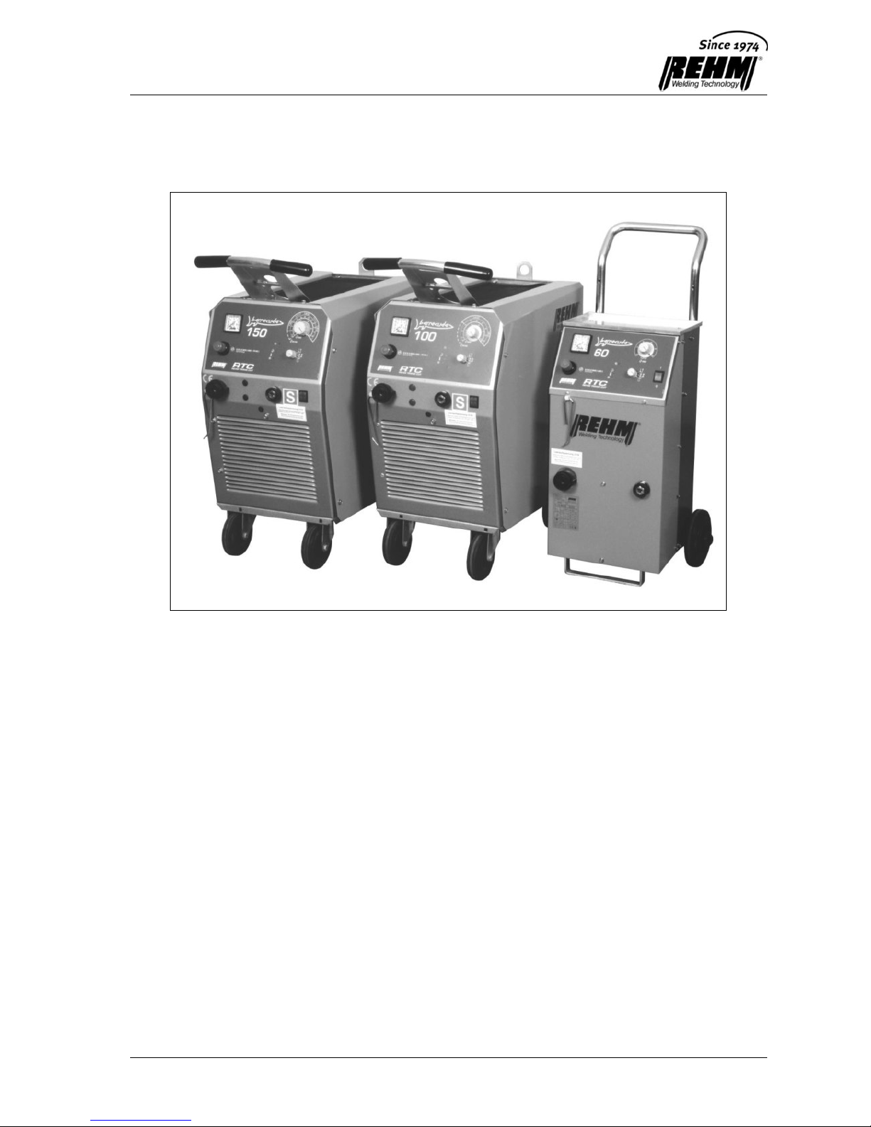
7
1.2 General Description
Fig.1 BARRACUDA

Introduction
8
1.2.1 Performance features of BARRACUDA cutting
equipment
Housing in REHM design
Improved ergonomics thanks to systematic and continuing enhancement of
the REHM design. The protected and well thought-out design means that
protection class IP23 is achieved. The equipment can therefore be used for
cutting outdoors.
REHM high-performance transformers
High-performance transformer with double enamelled wire, insulation class H
(180°C).
High-quality enamelled copper wire is used for all transformers.
All transformer windings are wound in layers, with inter-layer insulation.
REHM thermal protection
All REHM equipment is protected against overheating by thermal sensors.
REHM transistor heavy-duty circuit breaker
The patented REHM transistor heavy-duty circuit breaker, proved in tens of
thousands of instances, permits fine control of the cutting current, which is
continuously adjustable. Precise control with voltage compensation means
that cutting current can be held constant for maximum cut quality. The high
duty cycle values of 60% (10 mins.) are achieved safely through use of only
high-grade service components.
REHM safety system
With the monitoring of torches and wearing parts, with active early warning
and automatic safety shutdown aimed at damage prevention, the logic control
system offers the maximum safety for man and equipment.
REHM cost-effectiveness
Because the controlled pilot current is switched off during cutting and a soft
start function is standard, service life is longer and wear and tear is reduced.
Dependable ignition using REHM Zetronik is possible both for contact and
distant cutting. The quick start function permits immediate ignition, even
during the post-purge gas flow time. The post-purge gas flow time is demandoriented. Changing a torch on the central connector is simple and quick.
Material-oriented regulation of high-speed pilot and cutting current allows
uninterrupted cutting of perforated sheets.
1.2.2 Principle of plasma arc cutting
In plasma arc cutting operations, the material is melted using a high-energy arc.
In the plasma torch, air or gas is heated to such high temperatures that an
electrically conductive plasma is produced. The plasma issues from a nozzle as a
concentrated jet at high speed and thus forms the contact between electrode and
workpiece. The high energy density of the jet melts the material to be cut and
simultaneously blows it out of the kerf.

Introduction
9
1.2.3 Area of application of plasma cutting equipment
BARRACUDA cutting machines are direct-current sources. All conductive metals
can be cut using plasma arc cutting. The maximum material thickness to be cut in
each case depends on the arc power of the current source, the type of material
and the cutting speed used.
1.2.4 Function principle of REHM BARRACUDA cutting
equipment
All REHM BARRACUDA cutting equipment is continuously adjustable. This
means that it is possible for the user to quickly adapt it to the specific cutting
tasks. The cutting arc is extremely stable within broad limits thanks to internal
regulation of current. Fluctuations in the power supply are compensated in the
range between +6% and -10%.
High performance reserves guarantee the optimum material penetration and
constant cutting performance even under extreme requirements.
With REHM BARRACUDA cutting equipment both contact and distant cutting is
possible. In the case of contact cutting, however, the cutting current should not
exceed 50A.
In the development and design of this equipment, the priorities were the best
cutting characteristics, high efficiency, low wear and tear and simple operation
and handling.
All the components were tested extensively under practical conditions for heavyduty and industrial usage.
1.2.5 Proper use
REHM plasma cutting equipment is designed to cut all conductive metals. Please
note also any special regulations which may apply to your application. Please
contact your safety officer or REHM Customer Service if you have any queries.
Except where expressly stated otherwise in writing by REHM, REHM plasma
cutting equipment is only intended for sale to commercial or industrial users and
only for use by such users. It must be operated only by people who have been
trained and are qualified in the use and maintenance of plasma cutting
equipment.
Cutting current sources must not be positioned in areas where there is a
significant electrical hazard
see Chapter 5, Commissioning.
These operating instructions contain rules and guidelines for the proper use of
your equipment. Only use in accordance with these operating instructions will be
deemed to be proper use. Any risks which arise from other forms of use are the
responsibility of the operator. For special requirements, it may be necessary to
observe special additional conditions as well.
Please contact your safety officer or REHM Customer Service if you have any
queries.
Attention should be paid to the specific directions regarding proper use referred to
in the delivery documentation.
Any national regulations which are more stringent than the requirements of these
operating instructions also apply.

Introduction
10
Proper use also includes compliance with the specified conditions for installation,
dismantling, re-installation, commissioning, operation, maintenance and disposal
measures. Please heed in particular the information in the chapter on safety.
The equipment may be operated only under the above-mentioned conditions. Any
other form of use is deemed as not being proper use. The operator will be liable
for any consequences arising from improper use of the equipment.
1.3 Symbols used
Lists preceded by bullet point: general list
Lists preceded by square: working or operating steps which must be carried
out in the order listed.
Section 2.2, Warning symbols on the equipment
Cross-reference: in this case to Section 2.2, Warning symbols on the
equipment
Bold type is used for emphasis
Note:
... Indicates user tips and other particularly useful information.
For the safety symbols used in this manual,
Section 2.1.
Typographical
conventions
Safety symbols
Safety Instructions
11
2. Safety Instructions
2.1 Safety symbols in these operating instructions
You will find this symbol or one which specifies the danger more precisely
by all safety instructions in these operating instructions where there is a
risk to life and limb.
One of the following words (Danger!, Warning!, Caution!) indicates the
extent of the hazard:
Danger! ... There is an immediate danger.
If the hazard is not avoided, then death or serious injury will occur.
Warning! ... There is the possibility of a dangerous situation.
If the danger is not avoided, then death or serious injury could occur.
Caution! ... There is the possibility of a harmful situation.
If this is not avoided, light or minor injury could occur and damage could
be caused to property.
Important!
Reference to a possibly harmful situation. If it is not avoided, then the
product or something in the vicinity may be damaged.
Substances which are injurious to health and/or the environment. Materials
/ fuels which have to be handled and/or disposed of in accordance with
legislation.
2.2 Warning symbols on the equipment
indicate hazards and sources of danger on the equipment.
Danger!
Dangerous electrical voltage!
Disregarding the danger can lead to death or injury.
Warnings and
symbols

Safety Instructions
12
2.3 General
The equipment was designed and manufactured in accordance with generally
recognised technical regulations.
Nevertheless, risks of personal injury to the user or third parties or damage to the
equipment or to other material assets could arise during use.
Under no circumstances may any safety mechanisms be dismantled or taken out
of service, as this will result in exposure to danger and proper use of the
equipment is no longer guaranteed.
Dismantling of safety mechanisms during set-up, repair and maintenance is
described separately. Immediately after this work has been completed, the safety
mechanisms must be re-installed.
The operator of the equipment must ensure its safety during the use of external
agents (e.g. solvents for cleaning).
All safety and warning notices and the nameplate on the equipment must be kept
in a legible condition and must be heeded.
Safety instructions are intended to promote occupational health and safety and
prevent accidents. They must be observed.
It is important to observe not only the safety instructions listed in this chapter but
also the special safety instructions given throughout these operating instructions.
In addition to the instructions in these operating instructions, general safety and
accident prevention regulations (in Germany among others UVV VGB15 on
welding, cutting and associated processes, especially the references to arc
welding and cutting, or the appropriate national regulations) must also be
observed.
Please observe the safety notices in the operator’s workshop as well.
Dangers of
disregarding safety
instructions
Safety
instructions

Description of Function
13
3 Description of Function
3.1 Preparations for cutting
3.1.1 Mains connection and power-up
REHM cutting equipment is fitted with a Euro CEE plug for 3x400V three-phase
alternating current. The equipment is connected to the power supply voltage via
the main switch on the front side. The control lamp MAINS ON shows that the
equipment is ready for operation.
3.1.2 Adjustment of compressed air – gas test
The pressure and the flow rates for cooling and cutting air must in each case be
appropriately adjusted to the torch used. If the gas pressure is incorrectly set,
cutting quality will be reduced, wear and tear will be higher and, under extreme
conditions, the torch could be destroyed. The necessary air pressure must be
adjusted using the adjustment knob provided for this purpose on the control
panel.
To do so, turn the function selection switch to the “GAS TEST” position and pull
the blue adjustment knob upwards. Continue turning in this position until the
pressure displayed on the pressure gauge corresponds exactly to the required air
pressure. Then push the rotary knob back down to lock it. The setting is now
protected against inadvertent adjustment. After that, to begin cutting operation,
switch the function selection switch back to 2-step or 4-step operating mode.
3.1.3 Operating modes
3.1.3.1 2-step operating mode
In this operating mode, the torch button is kept pressed down throughout cutting
until cutting is terminated. Releasing the torch button terminates the cutting
operation, just as does extinguishing of the arc.
This operating mode is recommended for short, alternating cutting operations.
3.1.3.2 4-step operating mode
After ignition of the cutting arc, the torch button can be released. Reactivation and
release of the torch button terminates the cutting operation, just as does
extinguishing of the arc.
In this operating mode, it is possible to operate the torch effortlessly for extended
periods.
3.1.4 Choosing the cutting current
The current required depends essentially on the type of material to be cut and on
the material thickness Continuous adjustment of the cutting current supplied to
REHM BARRACUDA cutting equipment permits optimum adjustment to particular
cutting tasks.
If the current is set too high, this will lead to higher wear and tear of nozzle and
torch electrode. If the current is set too low, then either no material penetration
occurs or else this is too slow.

Description of Function
14
3.1.5 Nozzle selection
A plasma nozzle that is appropriate to the cutting current setting must be
selected. If the nozzle is too big, cutting performance is impeded, while too small
a nozzle will cause thermal overload and hence higher wear and tear.
To make the correct choice of nozzle, the areas of application of the various
nozzle diameters are shown on the cutting current adjustment dial.
Only replace parts with original REHM spare parts (see Chapter 4).
3.2 Cutting operation
3.2.1 General description
To achieve an optimal cutting quality, the choice of cutting current, nozzle and
cutting speed must take into account the type of material to be machined and the
thickness of the work piece.
Where light gauge sheet metal is to be cut, better cutting quality is achieved when
the torch is in contact with the material.
If thick sheets are to be cut, higher cutting performance is needed. Therefore
cutting must be performed with the torch held at a distance. The relevant spacer
elements will be found in the appendix entitled “Torches and accessories”.
In hand cutting operations, the quality of the cut and the amount of wear and
tear sustained by the torch components depends not only on the factors already
mentioned, but also on the skill of the user in handling the plasma torch.
Press torch button and move torch with pilot arc to the point at which the cut is to
start.
Following ignition of the cutting arc, draw the torch across the work piece at a
constant speed. The optimal cutting speed is achieved when the cutting jet is
facing towards the direction of cut and is inclined at approx. 10º from the kerf.
The pilot arc should not be ignited unnecessarily, as this will result in higher wear
and tear of the torch components.
With straight cuts, it is recommended using a stop rail to guide lateral movement
of the torch. To obtain even and stick-slip free movement of the torch, we
recommend using a torch carriage (see Chapter 4).
Description of Function
15
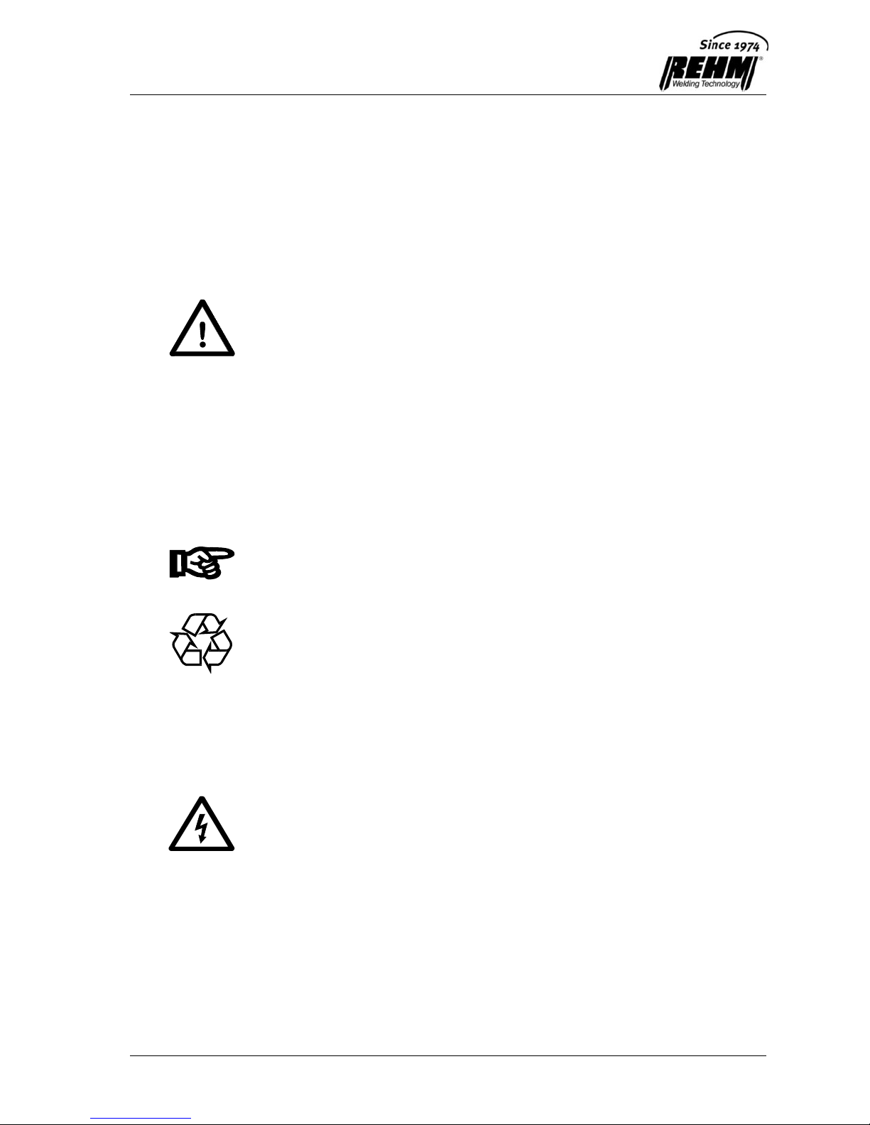
3.2.2 The REHM control panel
The plasma cutting equipment is operated using the REHM control panel shown
in Fig. 3.1.
Figure 3.1 Control panel on the BARRACUDA RTC 150 (RTC 60 and RTC 100
layouts are similar)
The control panel is divided into the following areas:
Measuring instruments for the compressed air setting
Cutting current selection knob
Rotary knob for compressed air setting
Control lamps
Function selection switch 2-step, 4-step, gas test
730 0178
1,
2
40
50
60
70
80
90
100
110
120
130
140
150
30
25
60
50
40
30
25
R145
A80
5,0-5,5 BAR ( A80 / R145 )
72,5-79,75 psi
150

Accessories
16
3.2.3 Symbols and their meanings
The symbols used on the control panel have the following meanings:
The cutting equipment is currently in 2-step cutting mode (see Section 3.2.4.1).
The cutting equipment is currently in 4-step cutting mode (see Section 3.2.4.2).
The cutting equipment is set to gas test. By pulling upwards and then turning
the blue adjustment knob, it is possible to set the required air pressure using
the pressure gauge (see Section 3.1.2).
Blue adjustment knob used to set the required air pressure. To do so, pull the
adjustment knob upwards and continue turning in this position until the
pressure displayed on the pressure gauge corresponds exactly to the required
air pressure (see Section 3.1.2).
Recommended range of adjustment on the current scale, using an electrode
diameter of 1.4 mm (the symbol is modified appropriately with other sizes).
R145
Current scale for torches R145 and R145P (see Section 4.3.2.2, “Machine
configuration”).
A80
Current scale for torch A80 (see Section 4.3.1.2, “Machine configuration”).
Control lamps
Wear and tear on the torch parts is displayed as follows:
Flashing: Early warning of increased level of wear and tear. It is
recommended that the wear parts are changed.
Continuous: Wear has exceeded permitted limits. Equipment will shut down.
The point in time at which the wear parts are changed is determined by the user.
There is a voltage at the torch. The pilot current is active, or following ignition of
the cutting arc the set cutting current is flowing.
The air pressure is no longer sufficient to supply the torch.
Equipment will shut down.
The cutting equipment has shut down due to excessive temperature. After it
has cooled down, the cutting equipment automatically reverts to operating
mode.
When heavily loaded, especially when cutting work takes place in a hot
environment, the overtemperature protection can switch off the welding current.
This is indicated by the control lamp.
Power supply voltage switch is switched on, power supply voltage is on (only
with RTC 60).

Accessories
17
3.2.4 Operating modes
3.2.4.1 2-step function sequence
Step 1 - Press torch button
Gas pre-flow time 4 seconds.
Pilot arc is ignited.
On contact with work piece, the cutting arc is ignited and the compressed air
is increased to the required throughput rate.
If contact is not made with the work piece within four seconds, the equipment
switches itself off automatically (safety shutdown).
Step 2 - Release torch button
Cutting current is interrupted, cutting voltage is switched off.
Post-purge gas flow time (demand-oriented).
If the torch button is pressed once again during the post-purge gas flow time,
no gas pre-flow will occur. Functional sequence is immediately restarted
(quick start).
3.2.4.2 4-step function sequence
Step 1 - Press torch button
Gas pre-flow time 4 seconds.
Pilot arc is ignited.
On contact with work piece, the cutting arc is ignited and the compressed air
is increased to the required throughput rate.
If contact is not made with the work piece within four seconds, the
equipment switches itself off automatically (safety shutdown).
Step 2 - Release torch button
- Prior to ignition of the cutting arc
Equipment switches to the basic setting (safety shut-down).
- After ignition of the cutting arc
Cutting operation is resumed.
If the torch is withdrawn during cutting, the arc is extinguished. This has the
effect of interrupting the cutting current and the equipment shuts down. This
function corresponds to the fourth step.
Step 3 - Press torch button
Cutting operation is resumed.
Step 4 - Release torch button
Cutting current is interrupted, cutting voltage is switched off.
Post-purge gas flow time (demand-oriented).
If the torch button is pressed once again during the post-purge gas flow time,
no gas pre-flow will occur. Functional sequence is immediately restarted
(quick start).

Accessories
18
3.3 Possible applications
3.3.1 Cutting of perforated sheets
Interrupted cuts, for example, cutting of perforated sheets, gratings etc., can only
be carried out in “2-step” operating mode. The functional sequence is identical to
the sequence involved in “2-step” mode up to beginning of the hole.
Moving towards the beginning of the hole:
Cutting current interrupted and/or cutting arc extinguished.
Compressed air is reduced.
Pilot current flowing / pilot arc active.
Moving towards the end of the hole:
W hen contact with material is resumed, the cutting arc is ignited and the
compressed air increases.
If contact is not made with the work piece within four seconds, the equipment
switches itself off automatically (safety shutdown).
3.3.2 Hole-piercing
Place torch obliquely across the work piece and ignite. Then slowly move the
torch to a vertical position until the material is penetrated.
Since during hole-piercing the molten spray can be released from the
material before the arc has penetrated the full material thickness, the
torch nozzle is particularly highly stressed due to splash back of the
material and thermal reflex reflection.
If the material is too thick, it is recommended to drill an appropriately
sized through-hole in advance so that it is possible for the material to
flow.
3.3.3 Gouging
Hold torch at an appropriate slant depending on the desired depth of penetration
and move it forwards in the direction of the molten material. This will then be
blown out of the groove as a result of the plasma pressure.
Depending on the type of seam preparation or machining desired, various
nozzles and/or torch configurations can be used for gouging (see Chapter 4).
3.3.4 Weld preparation
Move torch with appropriate nozzle (see Chapter 4) out of the vertical position
towards the side until the deviation corresponds to the desired angle of the
chamfer. Maintain position and move torch with even, adjusted speed.
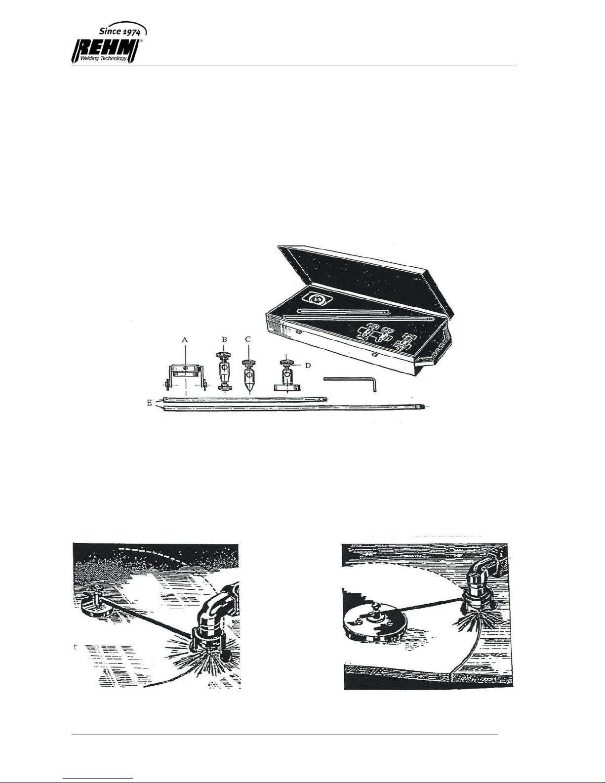
3.3.5 Circle cutting
Use of the circle cutting jig is recommended here in combination with the carriage
(see Chapter 4).

Accessories
19
3.4 Machine Functions
3.4.1 Gas pre-flow
A gas pre-flow occurs prior to the start of cutting. This avoids inadvertent ignition
of the pilot arc (safety). Moreover, it also means that the torch bundle is flushed
thoroughly and ensures even with unusually long hose bundles that the volume of
air needed for cutting is available to the torch. The predetermined time is four
seconds. This pre-flow time can be shortened using the quick start function.
3.4.2 Soft start
REHM BARRACUDA cutting equipment is equipped with a soft start function. On
ignition of the cutting arc, the cutting current is raised steadily to the pre-set value.
This increases the service life of the torch's wear parts.
3.4.3 Quick start
The gas pre-flow time can be reduced by pressing twice on the torch button. This
function makes it possible to start a work sequence rapidly. During the post-purge
gas flow time, pressing the torch button once is sufficient to interrupt the post-flow
time and immediately resume cutting operation.
3.4.4 Safety shut-down
If no cutting current arrives within four seconds when the pilot arc is on, the
equipment shuts down automatically. This avoids undue wear and tear on the
torch.
3.4.5 Post-purge gas flow time
To cool the torch sufficiently, the gas continues to flow after the end of cutting.
The post-purge gas flow time is based in a demand-oriented manner on the
cutting performance available during the cutting operation, divided into stages of
32, 64 or 96 seconds. If the torch button has been activated, but no cutting
operation occurred, the post-purge gas flow time is set to 12 seconds.
Important!
Under no circumstances should the equipment be shut down before the
post-purge gas flow time has finished, as otherwise the torch components
will not be adequately cooled.
3.4.6 Safety contact in plasma torch
All torches are fitted with a safety contact which only permits functioning to
commence if the torch is assembled in the proper manner. W hen wear parts are
changed, the contact is automatically interrupted for safety reasons so that cutting
operations cannot resume.
3.4.7 Detection of phase failure
REHM BARRACUDA cutting equipment is provided with automatic phase failure
detection. This prevents the equipment from being overloaded as a result of the
failure of one phase of the supply voltage. Depending on which phase fails, either
the green MAINS ON control lamp goes out and the equipment cannot be made
to work, or else, on ignition of the pilot arc, the power component switches off
again immediately (one can tell that this has occurred because the power
contactor pulls in and is then immediately released).

Accessories
20
4 Accessories
4.1 Standard Accessories
1 earthing cable with terminal (4m)
1 mains cable with connector (5m)
1 mono-gas plasma torch with central connector and safety switch (6m)
1 set of operating and functional instructions
1 set of wear parts (see appendix, “Torches and accessories”)
4.2 Options
4.2.1 80A torch for RTC 100 and RTC 150
Optional 60A torches enabling cutting of light gauge sheet metal with a smaller
nozzle are also available for the RTC 100 and RTC 150 units. From the coding of
the torch, the equipment can tell that an 80A torch has been connected. The
cutting current is automatically limited to 60A. The inside scale then applies to the
cutting current settings.
The permitted equipment duty cycle is based under this combination on the
maximum duty cycle of the 80A torch (see Section 4.3).
4.2.2 Automatic torch
Appropriate automatic torches can be employed for automated operations, e.g.
on cutting machines. The specification details will be found in Section 4.3.
When an automatic torch is used, a mechanised interlock may be necessary.
Please contact your supplier for further information about this.
4.2.3 Torch accessories
Details of accessories for the various types of torch will be found in Section 4.3.
4.2.4 Air filter attachment
If the REHM BARRACUDA cutting equipment is used in an environment in which
the air is heavily polluted, then use of an air filter attachment is recommended.
This consists of a protective frame and a filter unit which is very easy to replace
when heavily clogged. The air filter attachment can be retrofitted without difficulty.
4.2.5 Mechanised interlock
For automated use of the BARRACUDA equipment, an interface can be provided,
the signals of which are metallically separated.
Outputs: - Current-flowing message (CFL) for message “Cutting arc on”
- Group alarm
- Arc voltage (U) (e.g. for arc voltage height control)

Accessories
21
Inputs: - Cutting on (external contact instead of torch button)
- Cutting current (Iset)
Your supplier will be able to tell you about the various options for automated use
of REHM plasma cutting equipment.
4.2.6 Special voltages
REHM BARRACUDA cutting equipment can be supplied with a variety of power
supply voltages.
Please ask your supplier for further details.
4.3 Torches and accessories
All plasma torches for the BARRACUDA series are fitted with a special REHM pin
configuration on the central connector.
4.3.1 RTC 60 machine configuration
4.3.1.1 Standard accessories for RTC 60
Description
Order no.
Earthing clamp with terminal
360 0004
Mains cable with connector
360 0110
Plasma torch A80
766 0806
Set of wear parts
750 0727
Set of operating and functional instructions
730 0275

Accessories
22
4.3.1.2 Plasma torches A80 and P80 Aut
Torch: Plasma torch A80 (order no. 766 0806)
Plasma torch P80 Aut (order no. 766 0816)
Mono-gas plasma torch 6m with central connector and safety switch
Technical data for A80 torch
Maximum cutting current: 60A
Duty cycle at I
max
: 60%
Air pressure: 5-5.5 bar
Air flow rate: 105 l/min
Nozzle diameter: 1.2 mm for current range 10-60A
Set of wear parts: 2 nozzles diameter 1.2mm
1 double electrode
Item
Description
Order no.
Suitable for torch
A60
A80
1
Torch body A80
776 0507
x
x
1a
Gripper tube A80
776 0607
x
Torch body A80 Aut
776 0508
x
Torch sleeve A80 Aut
776 0608
x
2
O-ring A60/80
776 3501
x
x
4
Diffuser A60/80
776 6120
x
x
5
Double electrode A60/80
776 6003
x
x
7
Nozzle 1.2mm A60/80
776 6110
x
x
8
Electrode long A60/80
776 6004
x
x
9
Plasma nozzle long A60/80
776 6111
x
10
External protective nozzle A80
776 6312
x
18
Switch for A80
776 0606
x
19
Spacer spring A60/80
776 6404
x
x
20
Spacer with 4 castellations
776 6405
x
x
Adapter to adapt A60 to A80
776 0614
x
21
Carriage A80
776 7013
x
Circle cutting unit, complete
776 7009
x

Accessories
23
4.3.2 Machine configuration RTC 100 / RTC 150
4.3.2.1 Standard accessories RTC 100 / RTC 150
Description
Order no.
RTC 100
Order no.
RTC 150
Earthing clamp with terminal
360 0004
360 0111
Mains cable with connector
360 0134
360 0135
Plasma torch A80
766 1456
766 1456
Set of wear parts
750 0728
750 0729
Set of operating and functional
instructions
730 0275
730 0275
4.3.2.2 Plasma torches R145 and R145P
Torch: Plasma torch R145 (order no. 766 1456)
Plasma torch R145 automatic torch (order no. 766 1466)
Mono-gas plasma torch 6 m with central connector and safety switch
Technical Data
(Technical data for R145P is the same as for torch type R145)
Maximum cutting current: 150A
Duty cycle at I
max
: 100%
Air pressure: 5-5.5 bar
Air flow rate: 230 l/min
Nozzle diameter: 1.4mm for current range 40-60A
1.6mm for current range 70-120A
1.8mm for current range 110-150A
3.0mm for gouging
Set of wear parts: Nozzle diameter 1.4 mm
(RTC 100 / RTC 150)
1 nozzle diameter 1.6mm
(RTC 100 / RTC 150)
1 nozzle diameter 1.8mm (RTC 150)
2 electrodes (RTC 100)
3 electrodes (RTC 150)

Accessories
24
Torch R145 Automatic torch R145P
Item
Description
Order no.
Plasma torch R145
6m with central connector
766 1456
Automatic torch R145P 6m with central connector
766 6119
1
Torch body R145
766 0505
3
Torch body R145P
766 0506
2
O-ring
776 3502
4
Electrode
776 6005
4 A
Electrode, long
776 6006
5
Insulator
776 3503
6
Nozzle, 1.4mm
776 6112
Nozzle, 1.6mm
776 6113
Nozzle, 1.8mm
776 6114
Nozzle 3.0mm (for gouging)
776 6116
6 A
Plasma nozzle, long
776 6119
7
External protective nozzle (tapered)
776 6301
8
Spacer – contact plate
776 6406
8 A
Spacer (rounded)
776 6302
9
Spacer – contact plate
776 6407
9 A
Spacer (straight)
776 6303
10
Spring retainer support for no. 7 with two spacer rings
776 6413
10 A
Spacer spring
776 6409
Carriage
776 7016

Accessories
25
4.3.2.3 Accessories for torch R145
No.:
Description
Article no.:
4 A
Electrode, long
776 6006
6 A
Plasma nozzle, long
776 6119
7 A
External protective nozzle (cylindrical)
776 6304
10 A
Spacer spring
776 6409
11
Spacer for gouging and weld preparation
776 6410
12
Spacer with 2 castellations
776 6411
13
Spacer with 4 castellations
776 6412
Accessories
26
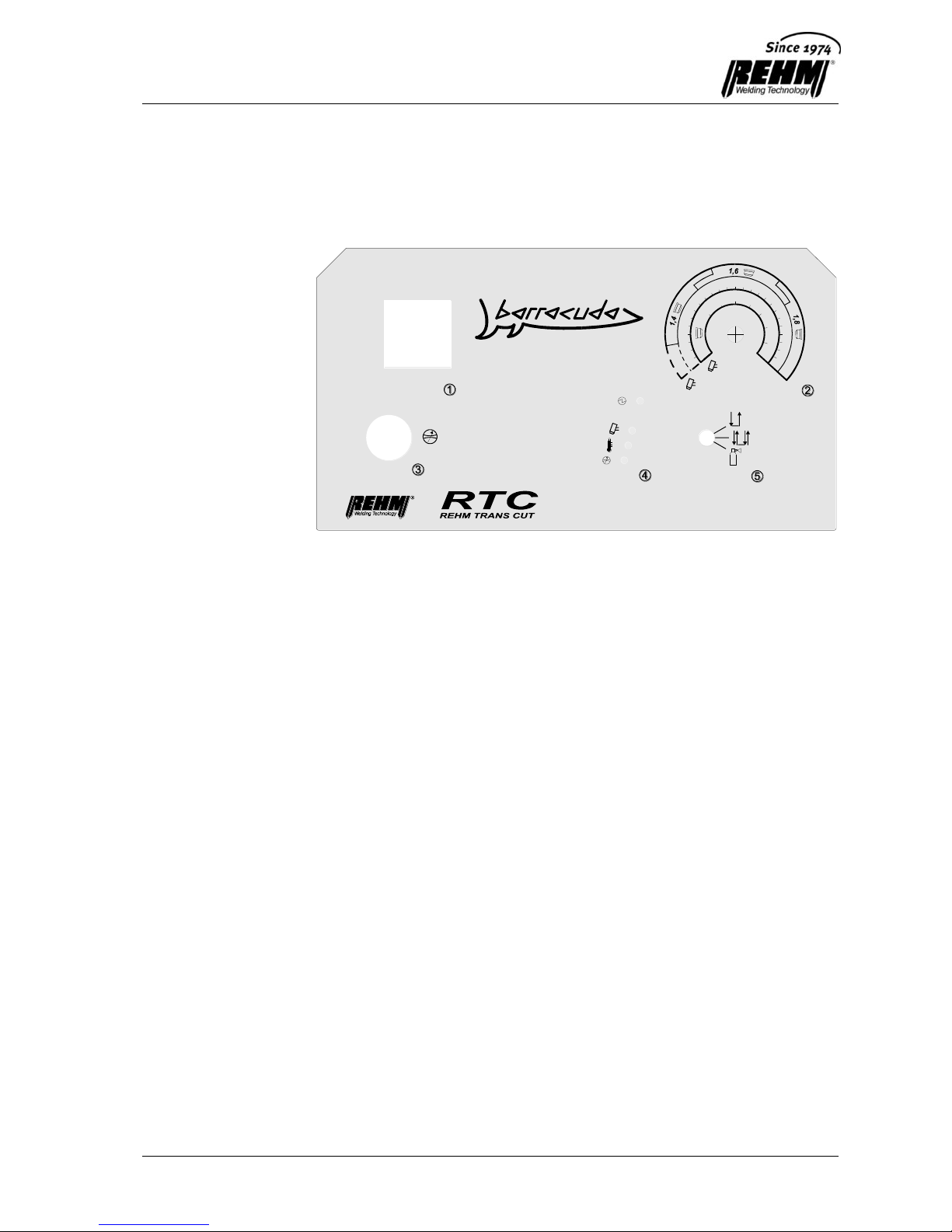
4.3.3 Circle cutting equipment and magnet clamps
Circle cutting equipment, complete, consisting of:
– Carriage (A)
– Threaded bracket (B)
– Centrepoint (C)
– Magnet clamp standard (D)
– Extendable compass bar (250mm and 400mm) (E)
Order number for RTC 60: 776 7010
for RTC 100 / RTC 150: 776 7015
Magnet clamp:
Standard (D) included in circle cutting equipment.
Diameter: 40mm
Maximagnet: article number 776 7017
Diameter: 75mm
Commissioning
27
5 Commissioning
5.1 Safety instructions
Please read the operating instructions carefully, especially
Chapter 2, Safety
Instructions, prior to commissioning of the equipment and before you begin
working on this cutting current source.
Warning!
REHM plasma cutting equipment may only be operated by personnel
trained and instructed in the use, maintenance and safety provisions of
plasma cutting equipment.
Always wear protective clothing during cutting and ensure that other
people who are in the vicinity are not endangered by UV radiation from the
arc.
5.2 Working under increased electrical danger in
accordance with the provisions of IEC 974, EN
60974-1 and VBG 15 (S)
REHM plasma cutting equipment complies with the above regulations.
Care should be taken that the cutting current source is not set up in this area
when working under increased electrical danger. Please observe regulations EN
60974-1 and VBG 15.
5.3 Transport and set-up of the plasma cutting
equipment
Set up the REHM plasma cutting equipment so that the user has sufficient room
in front of the equipment to monitor and operate the controls.
Set up the REHM plasma cutting equipment so that there are no obstructions of
the air intake and outlet. The stated duty cycle of the equipment can only be
achieved if there is adequate air throughput.
When transporting the unit, always comply with the applicable accident prevention
regulations. When transporting the unit with a crane, use the lifting rings attached
to the housing.
Danger! Electric voltage
Do not use the plasma cutting equipment in the open air when it is raining!

Commissioning
28
5.4 Connection of the plasma cutting equipment
Connect the REHM cutting current source to the power mains in accordance with
the current provisions of VDE (Association of German Electrical Engineers) and
also observe the regulations of the appropriate safety authorities.
REHM cutting equipment is fitted with a Euro CEE plug for 3x400V three-phase
alternating current. When connecting the unit, observe the information regarding
the supply voltage and fuse protection. Automatic circuit breakers and fuses must
always be rated for the current indicated. You will find the necessary details in
Chapter 12, Technical Data.
Always switch off the equipment when it is not in use.
Where shielding gas cylinders are used, set these up separately and secure them
against falling over. Screw the cylinder pressure regulator onto the cylinder thread
and check the connection for tightness. Always close the cylinder valve after
working. Observe the appropriate regulations of the competent safety authorities.
5.5 Cooling of the plasma cutting equipment
Set up the REHM plasma cutting equipment so that there are no obstructions of
the air intake and air outlet. The stated duty cycle of the power components can
only be achieved if there is adequate ventilation (see “Technical Data”). Ensure
that no grindings, dust, metal parts or other foreign matter can get into the
equipment.
5.6 Compressed air supply
The rapid plug-and-socket connection for the compressed air supply is located on
the back of the equipment. The pressure must be at least 7 bar to ensure that the
cutting equipment has a sufficient supply.
The compressed air line must be adequately dimensioned. Where compressed
air lines are relatively long, the next higher cross-section should be chosen.
The compressed air provided must be clean, dry and oil-free. If the compressed
air is significantly contaminated, the unit should also be fitted with a fine mesh
microfilter (see REHM catalogue of accessories).
5.7 Guidelines for working with cutting current
sources
Only skilled workers or operators who have received appropriate instruction in the
equipment and procedures should be entrusted with cutting work. Always wear
protective clothing during cutting work and make sure that no one else who is
close by is exposed to any hazard. Following completion of the cutting work, you
should leave the equipment switched on for a few more minutes to allow the fan
to continue to run and the heat in the unit to be dissipated.
Commissioning
29
5.8 Connection of work piece return cables/torch
Connection of the earthing cable
The appropriate cable is inserted into the socket on the front side and locked in
position. The earthing clamp must be attached at an exposed place on the
workpiece or on the cutting table. Take care to ensure that the current can be
transferred smoothly.
Connection of the torch
REHM-RTC cutting equipment is fitted with rapid plug-and-socket connections
(central connector with REHM inscription) for connection of the plasma torch. The
torch is inserted and must then be connected securely by manually tightening the
coupling nut. This entails pressing the safety pin on the central connector with the
patent key. The patent key is fastened above the central connector and must be
used both to connect and to disconnect the torch.
Important!
To avoid unnecessary energy losses during cutting, take care to ensure that all
work piece return cable connections are properly tightened and well insulated.
5.9 Recommended cross-sections of welding power
supply cables
Cross-sections of copper cables:
With lengths
up to 5m
up to 10m
up to 15m
up to 60A
16 mm2
25 mm2
25 mm2
up to 100A
25 mm2
25 mm2
35 mm2
up to 150A
35 mm2
35 mm2
50 mm2
5.10 Connection to jigs
With the optional mechanised interlock, all REHM plasma cutting equipment can
be connected easily to a cutting machine or automatic fixture via the built-in
remote control socket. For further information on this point, see Section 4.2.6.If
you have any further questions, please contact your REHM dealer.
Important!
Please use the cover provided to protect the remote control socket from dirt when
not in use.
Operation
30
6 Operation
6.1 Safety instructions
Please read the operating instructions carefully, especially
Chapter 2, Safety
Instructions, prior to commissioning of the equipment and before you begin
working on this welding current source.
Warning!
REHM plasma cutting equipment may only be operated by persons who
have been trained and instructed in the use and maintenance of plasma
cutting equipment and in the safety provisions that apply thereto.
Working on and servicing electrical plasma cutting equipment is always
potentially hazardous. Personnel not familiar with such equipment and machinery
could hurt themselves or others. For this reason, operators must be told of the
potential hazards outlined below and of the safety measures that are necessary to
avoid possible injury. Irrespective of this, anyone operating plasma cutting
equipment must familiarise himself with the safety regulations that apply in the
relevant working area prior to starting work.
6.2 Electrical Hazards
Connection of and maintenance work on plasma cutting equipment and its
accessories may only be carried out in compliance with current VDE (association
of German electrical engineers) provisions and the regulations issued by the
appropriate safety authority. Ignition of the arc and cutting require a very high
voltage.
Warning!
The no-load voltage with plasma cutting equipment is over 100V.
- Never touch any live metal parts with the bare skin or with wet clothing.
- When cutting, always wear gloves and protective hoods fitted with approved
protective filters.
- Take care to ensure that all parts which you have to touch during your work,
such as your clothing, your working area, the welding torch, the electrode
holder and the plasma cutting equipment, are always dry.
- Take care to ensure that there is good insulation by only wearing dry gloves
and boots with rubber soles, and by standing on a dry, insulated base,
especially if you have to stand on metal during your work or are working in
areas with significant electrical hazards.
- Avoid using any power cables that are worn or damaged. Ensure that power
cables are not overloaded. Use only equipment that has no faults.
- Switch off the plasma cutting equipment whenever work is interrupted for any
length of time.
- Do not wind the cutting cable around any part of the housing and do not let it
lie wound up in coils.
- Never leave the plasma cutting equipment switched on and unsupervised.
- Only ignite the pilot arc against the work piece.

Operation
31
- Take careful note of the performance data relating to the torch and cutting
equipment. If the permitted values are exceeded, this could lead to
irreparable damage.
- Do not touch any current-carrying parts. Do not hold the work piece tightly.
- Do not move the hose bundle into the splash zone of the material.
- Avoid damaging the hose bundle on sharp edges.
- Do not perform any cutting in wet or moist surroundings.
- Replace defective parts immediately.
- Do not repair damaged torches and hose bundles, but replace them instead.
- Always switch the equipment off before replacing torches, wear parts or
damaged parts.
- Use only original REHM spare parts.
- Repair work may only be carried out by qualified technicians who have been
trained by REHM. Before opening the housing of the plasma cutting
equipment, it must have been disconnected from the power supply, e.g. by
pulling out the plug. When the housing is open, the device must not be
operated and must be disconnected from the power supply.
6.3 Information for your personal safety
Extremely high temperatures, infra-red and ultraviolet radiation can occur during
plasma arc cutting. Radiation from the electrical arc and hot metal can cause
serious burns to unprotected skin and eyes.
- To protect the eyes and body from sparks and radiation from the arc, please
use only welders’ protective hoods that are free of defects and are fitted with
approved protective filters (protection level 11-13), leather gloves and a
welding helmet (see VBG 15, §27). Wear the same protective clothing even
when you are only supervising the cutting work.
- Inform anyone in the vicinity of the hazards of arc radiation and hot metal
splashes, and protect them with non-flammable shielding.
- Never point the cutting jet at persons or objects.
- Compressed gas cylinders constitute a potential hazard. Therefore comply
strictly with the safety regulations issued by the relevant safety authorities and
suppliers. Safeguard shielding gas cylinders against falling over.
- Use appropriate protective clothing such as welding aprons, gloves, headgear
and safety shoes. Make sure that your clothing cannot catch sparks or
cinders. For example, wear trousers without turn-ups.
- Do not wear contact lenses during work, (there is a danger that the lens could
burn onto the cornea).
- Take care to ensure that reflection and transmission of radiation are not
possible in the cutting area. Use dark surfaces, for example, to reduce
reflections, and use guard shields and safety partition panels.
6.4 Fire Protection
- Hot cinders or sparks can trigger fires if they come into contact with
flammable materials, liquids or gases. Remove all inflammable and explosive
materials from the cutting area and have a fire extinguisher to hand.
- Never perform cutting work on containers used to hold fuel, lubricants or
other combustible materials, even if they are empty.

Operation
32
- Where the ambient air contains high concentrations of inflammable vapours,
combustible gases or dust, cutting work may only be performed if the area is
properly ventilated.
- If hydrogen is used or is present, it should be noted that it is an inflammable
gas and that there is a potential danger of explosion.
- If aluminium is cut underwater or directly on water, the high temperature of
the plasma can trigger decomposition of the water into oxygen and hydrogen.
The combination of oxygen with hot aluminium can result in dangerously high
concentrations of the remaining hydrogen. This concentration of hydrogen
can be avoided by using suitably designed air agitation units on the table
bottom.
- Only use pressure regulators that are in good condition and only for the
gases for which they are intended. Never lubricate pressure regulators with
grease or oil.
6.5 Ventilation
- During cutting work, poisonous gases can be given off as a result of melting
of the material. Wear protective masks!
- Workstations must be designed taking into account the methods, materials
and conditions of use, so that the air inhaled by the user can be kept free of
substances harmful to health (see VBG 15, 4 and 29).
- Take care to ensure that the cutting area is ventilated either by natural
ventilation or by appropriate technical devices.
- Do not perform any cutting work on workpieces that are painted or treated
with degreasing agents, which can cause poisonous vapours to be given off.
The material to be cut must be cleaned of any solvent or degreasing agent.
- Solvents containing chlorine or materials containing lead, graphite cadmium,
zinc, mercury or beryllium or are coated with these can give off poisonous
fumes that could be a health hazard.
6.6 Checks before switching on
It is assumed that:
- the unit was set up properly in accordance with Chapter 5,
Commissioning;
- all connections (shielding gas, torch connection) were established in the
proper fashion in accordance with Chapter 5, Commissioning;
- maintenance work has been carried out at the due intervals Chapter 8,
Maintenance;
- the safety devices and equipment components (especially the torch
connection hoses) have been checked by the operator and are in proper
working order;
- the operator and other persons involved have put on the appropriate
protective clothing, and the working area has been shielded so that no
bystanders are at risk.

Operation
33
6.7 Connection of the earthing cable
Warning!
Section 6.2 Electrical Hazards. Take care to ensure that the welding
current cannot flow through hoist chains, crane ropes or other components
that conduct electricity.
Section 6.2, Electrical Hazards. Ensure that the earthing cable is
connected to the work piece as close to the welding location as possible. If
the earthing cable is not connected to the work piece near to the welding
location, the effectiveness of earthing will be reduced and the risk of
electric shock and stray currents will be increased.

Safety Instructions
34
7 Faults
7.1 Safety instructions
Warning!
In the event of a fault which constitutes a danger to persons, equipment
and/or the surroundings, switch off the equipment immediately and ensure
that it cannot be switched back on.
Do not resume operation of the equipment until the cause of the
malfunction has been eliminated and there is no longer any hazard to
persons, equipment and/or the environment.
Faults should be rectified only by qualified staff observing all safety
instructions.
Chapter 2.
The equipment must be inspected and approved by qualified staff before it
is used again
Troubleshooting Table.
If the equipment is properly set up and handled, plasma cutting using the REHM
BARRACUDA cutting equipment will become a simple, reliable separation
process. If nevertheless any faults should occur, we would like to give you the
following practical advice and tips on how to eliminate them. If you are unable to
solve the problem using this information, we would ask you to contact your
supplier, who will be happy to help you further.
General information:
Different metals, especially non-ferrous metals, have quite different heat
conduction properties, which have an effect on the appearance of the cut
surface/cutting results. In such cases, you should check whether alteration of the
current setting, the nozzle, the distance from the work piece or the speed at which
the torch is moved could produce better results.

Trouble-Shooting Table
35
7.2 Troubleshooting Table
Control lamp MAINS ON (green) has gone out – not working
Cause Remedy
Mains or phase voltage missing Check fuses and voltages
Fault in mains cable or plug Check these
Equipment will not switch on – control lamp OPERATION (green) has gone out
Cause Remedy
Operation blocked by one of the yellow See “Control lamps”
control lamps
Faulty torch button or hose bundle Service required!
Torch not properly assembled after Check this
replacement of wear parts
Control lamp OPERATION (green) is on steadily
Cause Remedy
Torch button faulty (short-circuit) Check torch button
Control defective Service required!
Control lamp TORCH (yellow) is lit
Cause Remedy
Torch parts are worn Change wear parts
Control lamp TEMPERATURE (yellow) is lit
Cause Remedy
Maximum duty cycle exceeded Allow equipment to cool down, and clean it if
necessary
The air inlet or air outlet is clogged or Clean, make sure air can circulate freely,
blocked if necessary fit air filter attachment
Control lamp AIR PRESSURE (yellow) is lit
Cause Remedy
Air pressure too low Provide the required air pressure
WATER control lamp (yellow) is lit (only with water cooling option)
Cause Remedy
Water pressure too low, not enough water Replenish water
Water pump fuse has blown Check fuse and replace if appropriate
Water pump defective Service required!

Trouble-Shooting Table
36
Fans do not operate
Cause Remedy
Fuse has blown Change fuse
Fan defective Service required!
Pilot arc difficult to ignite or will not ignite
Cause Remedy
Plasma nozzle or electrode worn Replace wear parts
Water in compressed air Check and if necessary insert fine mesh
micro filter
Failure of one phase of the power supply voltage Check fuse
No cutting current available
Cause Remedy
Workpiece too far from nozzle Check out
Torch faulty Replace torch
Failure of one phase of the power supply voltage Check fuse
Workpiece not connected Check earthing cable and earthing clamp
Weak cutting performance
Cause Remedy
Wrong nozzle Change nozzle
Wrong distance from workpiece Correct
Wrong current setting Correct
One phase of power supply voltage missing Check fuse
Poor earth connection Check out
Cutting arc is extinguished
Cause Remedy
Cutting speed too high Reduce speed
Torch too far away Move closer
Plasma jet is a green colour
Cause Remedy
Torch electrode or nozzle faulty Check and if necessary replace

Trouble-Shooting Table
37
High consumption of wear parts
Cause Remedy
Wrong nozzle being used Check and if necessary correct
Air is moist or dirty Check
if necessary, fit fine mesh micro filter
Original REHM spare parts not in use Check out
Cutting performance too high for Check handling
workpiece contact
Pilot arc ignites too often in the air Check handling
Insufficient penetration
Cause Remedy
Cutting speed too high Reduce speed
Torch inclined at too great an angle Correct torch angle
Material too thick Check cutting current setting

Maintenance and Repair Work
38
8 Maintenance Work
8.1 Safety instructions
Warning!
Repair and maintenance may only be carried out by persons who have
received appropriate training from REHM. Please contact your REHM
dealer. When replacing parts, use only original REHM spare parts.
If maintenance or repairs are undertaken by persons who have not been
trained by REHM and are not authorised for this work, then REHM will not
accept any liability or warranty claims.
The plasma cutting equipment must be switched off and disconnected from
the mains supply before cleaning commences!
Before maintenance is carried out, the welding unit must be switched off
and disconnected from the mains supply and protected against being
switched back on inadvertently.
Supply hoses must be blocked off and depressurised.
The warnings contained in
Chap.2 "Safety Instructions" must be
observed.
The welding equipment and its components must be maintained in accordance
with the specifications in the operating and maintenance instructions.
Inadequate or inappropriate maintenance or repair work can lead to technical
faults during operation. Regular maintenance of the equipment is therefore
essential. No structural modifications or additions to the equipment may be
undertaken.
Before maintenance is carried out, the welding unit must be switched off
and disconnected from the mains supply and protected against being
switched back on inadvertently.
.
8.2 Maintenance table
The maintenance intervals are recommended by REHM for normal standard
requirements (e.g. one-shift operation, use in clean, dry surroundings). The
precise intervals will be determined by your safety officer.
Activity
Chap.
Interval
Cleaning of equipment interior
8.3
Depends on conditions of
use
Function testing of safety devices by
operating staff
Daily
Visual checking of the unit, especially
the torch hoses
Daily

Maintenance and Repair Work
39
Activity
Chap.
Interval
Checking that fault-current circuit
breaker is working.
Daily
(with unsupported work)
Otherwise monthly
Have supply cables and torch hoses
inspected by qualified staff; inspection
noted in the appropriate test book.
Inspection to be carried out more
frequently if required by national
legislation.
Every 6 months
Have entire welding equipment
inspected by qualified staff; inspection
noted in the appropriate test book.
Inspection to be carried out more
frequently if required by national
legislation.
Once a year
8.3 Cleaning of equipment interior
If the REHM plasma cutting equipment is used in a dusty environment, the interior
of the unit must be cleaned regularly by blowing-out or suction.
The frequency with which this cleaning has to be performed depends on the
conditions of use. Use only clean, dry air for blowing-out or use a vacuum
cleaner.
8.4 Proper waste disposal
Only for EU countries!
Do not dispose of electric tools together with household waste material!
In observance of European Directive 2002/96/EC on waste electrical and
electronic equipment and its implementation in accordance with national law,
electric tools that have reached the end of their life time must be collected
separately and returned to an environmentally compatible recycling facility.

Circuit Diagrams
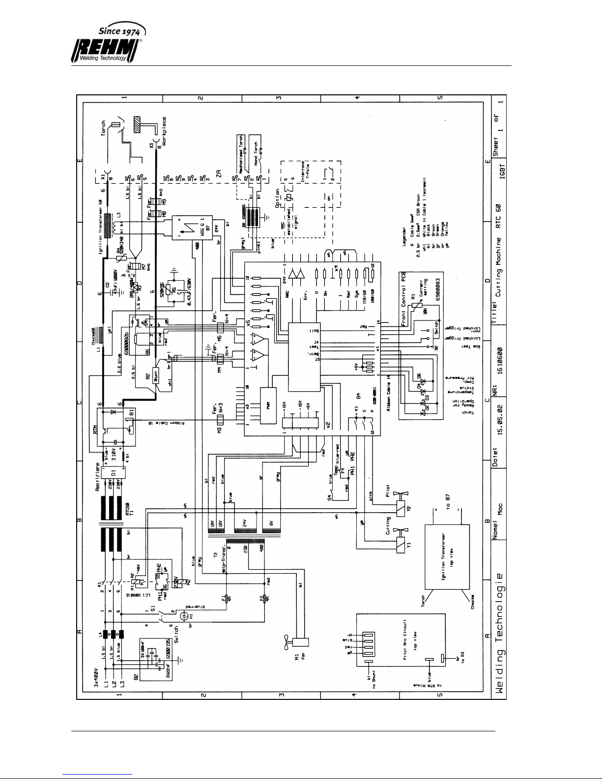
40
9 Circuit diagrams

Circuit Diagrams
41
Circuit Diagrams
42

List of Components
43
10 List of Components
10.1 Sparepart list REHM RTC
Drawing No.
Name
RTC 60
RTC 100
RTC 150
1
Suspension
2000757
2000757
2
Nipple
3100014
3100014
3100014
3
Compressed air filter
3100076
3100076
3100076
4
Control panel foil
7300176
7300177
7300178
5
Insulating bolt
3400108
3400108
3400108
6
Compressed air unit
2200286
2200287
2200287
7
Pressure gauge
3100049
3100049
3100049
8
Earth socket
4300023
4300023
4300023
9
ground cable
7810100
7810100
7810101
10
Torch suspension
7560102
7560102
7560102
11
Plasma torch
7660806
7661456
7661456
12
Pilot resistor
5100008
5100008
5100008
13
HF unit
6900020
6900020
6900020
14
Fan
4100008
4100008
4100008
15
Main rectifier
5300054
5300040
5300040
16
Main transformer
2200270
2200271
2200272
17
Choke unit
2200406
2200338
18
Welding chocke
2200273
19
HF chocke
2200283
20
Side panel left
2000734
2000734
21
Front panel
2000611
22
Front panel
2000729
2000729
23
Handle
2100534
2500061
2500061
24
Cover 3300165
3300165
25
Surge filter
6900085
6900085
6900085
26
Rotary knob
2600055
2600055
2600055
27
Rotary knob
2600053
2600053
2600053
28
Power line switch
4200051
4200051
4200051
29
Capacitor
5200087
30
Pilot switch
6900082
6900082
6900082
31
Chopper
2200276
2200278
2200278
32
Shunt
6700019
6700020
6700021
33
Control panel
6900083
6900083
6900083
34
Main control panel
6900115
6900115
6900115
35
Side panel left
2000732
2000732
36
Block roller
2500011
2500006
2500006
37
Caster wheel
2500005
2500005
38
Mains cable
3600110
3600134
3600135
39
Thermostat
6600021
6600021
6600021
40
Interference suppressor
6900102
6900185
6900185
41
Instruction manual
7300275
7300275
7300275
42
Fan cable
3600069
3600069
3600069

List of Components
44
Drawing No.
Name
RTC 60
RTC 100
RTC 150
Compressed air unit
2200286
2200287
2200287
44
Solenoid Valve
4200113
4200113
4200113
45
Pressure switch
6600022
6600022
6600022
46
Pressure regulator
3100079
3100079
3100079
47
Threaded connector
3100085
3100085
3100085
48
Tee
3100016
3100016
3100016
49
Threaded connector
3100073
3100073
3100073
50
Quick-screw joint
3100007
3100007
3100007
51
Tee
3100034
3100034
3100034
52
Hose line f. compr. Air
3200003
3200003
3200003
E-box
53
Main contactor
4200151
4200152
4200152
54
Control transformer
4700052
4700052
4700052
55
Fuse socket
4300170
4300170
4300170
56
Power-line filter
6900195
6900195
6900195
57
Relays
4200153
4200153
4200153
58
Relays socket
4200154
4200154
4200154
59
Mounting support
4200158
4200158
4200158
60
Protection key
2101260
2101260
2101260
Fuse F1 4A
6600043
6600043
6600043
Fuse F2 4A
6600043
6600043
6600043
Fuse F3 1A
6600043
6600043
6600043
Fuse F5 4A
6600043
6600043
6600043

List of Components
45
1
2
3
6
7
4
8
9
10
11
12
13
14
15
42
16
39
17
20
22
5

List of Components
46
38
23
24
25
26
27
60
28
29
30
31
34
E-Box
33
35
36
37
32
40
F3, F5

List of Components
47
54
57
55(F1, F2)
56
53
59
58
44
47
45
46
52
51
50
48
49
Compressed air unit
E-Box

Mechanised Interlocks
48
11 Mechanised interlocks
Mechanised interlocks with metallic separation are only available factory
fitted.
11.1 RTC units with 7-pin interface (only for RTC 100
and RTC 150)
Input: – “Cutting on/off” closing contact, always required.
Output:– “Current-flow” message contactless for “Cutting arc on” Can be used for
external further processing, e.g. as precondition to starting control or
similar.
Article number: 756 1152
Standard: 5m cable
11.2 RTC units with 17-pin interface (only for RTC 100
and RTC 150)
Inputs: – Current set point for the range l
min
to l
max
linear 0-10V or connection of
potentiometer (< = 10 kOhm)
– “Cutting on/off” closing contact or “On” if U>18V
Outputs: – “Current-flow” message contactless for “Cutting arc on” Can be used
for external further processing, e.g. as precondition to starting
control or similar.
– Group alarm “RTC unit fault” by closing contact. Can be used for
external further processing, e.g. as error message on control or
similar.
- Actual value of cutting voltage 0-5V linear for 0-500V.Can be used
for external further processing, e.g. for arc voltage height control or
similar.
Article number: 756 1010
Standard: 5m cable

Mechanised Interlocks
49
11.3 Connection schematic for 7-Pole mechanised
cutting interface
Control
A1
white
brown
grey
pink
Plug Socket
Interference
protection
PCB A8
On/Off
signal
Arc
established
signal

Mechanised Interlocks
50
11.4 Connection schematic for A-pole mechanised
cutting interface

Technical data
51
12 Technical Data
Model RTC 60
RTC 100
RTC 150
Continuous range of adjustment
[A]
10 - 60
15 - 100
25 - 150
Duty cycle at
I
max.
(10 min)
[%]
60
60
60
Current / voltage at 60% duty
cycle
[A / V]
60 / 95
100 / 115
150 / 140
Current / voltage at 100 % duty
cycle
[A / V]
50 / 90
80 / 105
130 /130
Max. cutting performance
[kW]
5.7
11.5
21
No-load voltage
[V]
310
310
310
Power consumption at I
max.
[kVA]
7.5
13.5
24.5
Current consumption at I
max.
[A]
11
19
35
Power supply voltage
[V]
3 x 400
3 x 400
3 x 400
Power frequency
[Hz]
50
50
50
Mains voltage compensation
-10% +6%
-10% +6%
-10% +6%
Fuse protection
[A]
16
20
35
Power factor
cos
0.97
0.97
0.97
Protection class
IP 23
IP 23
IP 23
Insulation class
H H
H
Type of cooling
Fan
Fan
Fan
Torch cooling
Mono-gas/air
Mono-gas/air
Mono-gas/air
Compressed air supply
[bar]
min 7 – max 10
min 7 – max 10
min 7 – max 10
Dimensions L/W/H
[mm]
345/460/885
655/375/885
655/375/885
Weight
[kg]
54
95
129

Index
52
13 Index
A
accessories 20
accident prevention 12
alterations to the equipment 6
areas of application 6
C
checks before switching on 32
circuit diagrams 40
cleaning of equipment interior 39
commissioning 27
connect earthing cable 33
connection of the earthing cable 33
connection of the welding equipment 28
control panel 15
H
health and safety 12
L
list of components 43
M
machine description 2
maintenance work 38
manufacturer 2
O
operation, checks before switching on 32
other applicable regulations 9
P
performance features of TIG welding equipment 8
product identification 2
machine description 2
type number 2
proper use 10
purpose of the document 6
Q
qualifications, staff 6
R
residual risks 12
S
safekeeping of instructions 6
safety, dangers of disregarding safety instructions 12
safety instructions 5, 11, 12
safety regulations 30, 31
safety symbols 5, 11
symbols 10

Index
53
T
table of contents 3
technical data 51
TIG welding 8
type number 2
typographical conventions 10
W
warning symbols on the equipment 11
warnings and symbols, presentation 11

EC Declaration of Conformity
We hereby confirm that the following products
Plasma Cutting Equipment
BARRACUDA RTC 60
BARRACUDA RTC 100
BARRACUDA RTC 150
meet all the major protection requirements laid down in the Council Directive 2004/108/EC (EMC directive)
on the approximation of the laws of the Member States relating to electromagnetic compatibility and
stipulated in the Directive 2006/95/EC relating to electrical equipment designed for use within certain
voltage limits.
The aforementioned products comply with the provisions of this Directive and meet the safety requirements
applicable to equipment for arc welding in accordance with the following product standards:
EN 60 974-1: 2006-07
Arc welding equipment – Part 1: Welding power sources
EN 60 974-2: 2003-09
Arc welding equipment – Part 2: Liquid cooling systems
EN 60 974-3: 2004-04
Arc welding equipment – Part 3: Arc striking and stabilizing devices
EN 60 974-8: 2004-12
Arc welding equipment – Part 8: Gas consoles for welding and plasma cutting systems
EN 60974-10: 2004-01
Arc welding equipment – Part 10: Electromagnetic compatibility (EMC) requirements
According to EC Directive 2006/42/EG Article 1, para. 2, the above products come exclusively within the
scope of Directive 2006/95/EEC relating to electrical equipment designed for use within certain voltage
limits.
This declaration is made on behalf of the manufacturer:
REHM GmbH u. Co. KG Schweißtechnik
Ottostr. 2
73066 Uhingen Germany
Uhingen, 24 April 2007
Declaration made by
R. Stumpp
Managing Director

by REHM, Printed in Germany
No: 730 1200 06 / 2013
GB
 Loading...