

Page 1
EN
v. 1.0
REGOMAT PUMP STATION
- for boilers and fireplaces
Instruction Manual
Page 2
1. Introduction
REGOMAT Pump Station makes boiler installation quicker as it contains all important
components needed for boiler protection. It is designed to be installed directly on a
boiler incoming pipe or on a wall. The distance between the pipe axis and wall shall
be at least 100 mm to enable insulation removal.
This pump station is intended for solid-fuel boilers and fireplaces.
2.
Description
Regomat keeps the return temperature to a boiler (fireplace) at or above the valve
opening temperature, which prevents low-temperature corrosion and boiler fouling.
This prevents condensation and boiler tarring. The boiler then works with higher
efficiency and its service life is extended.
Parameters of REGOMAT pump station
Fluid operating temperature
2 - 95 °C
Max. working pressure
6 bar
Max. ambient temperature
70 °C
Max. rel. humidity
95 % non condensing
Power supply
230 V, 50 Hz
Insulation material
EPP RG 60 g/l
Overall dimensions
325×140×150 mm (W×H×D)
Total weight
3.25 kg
Connection
3× G1" F
Installation
boiler return pipe (min. pipe axis to wall distance is 100 mm)
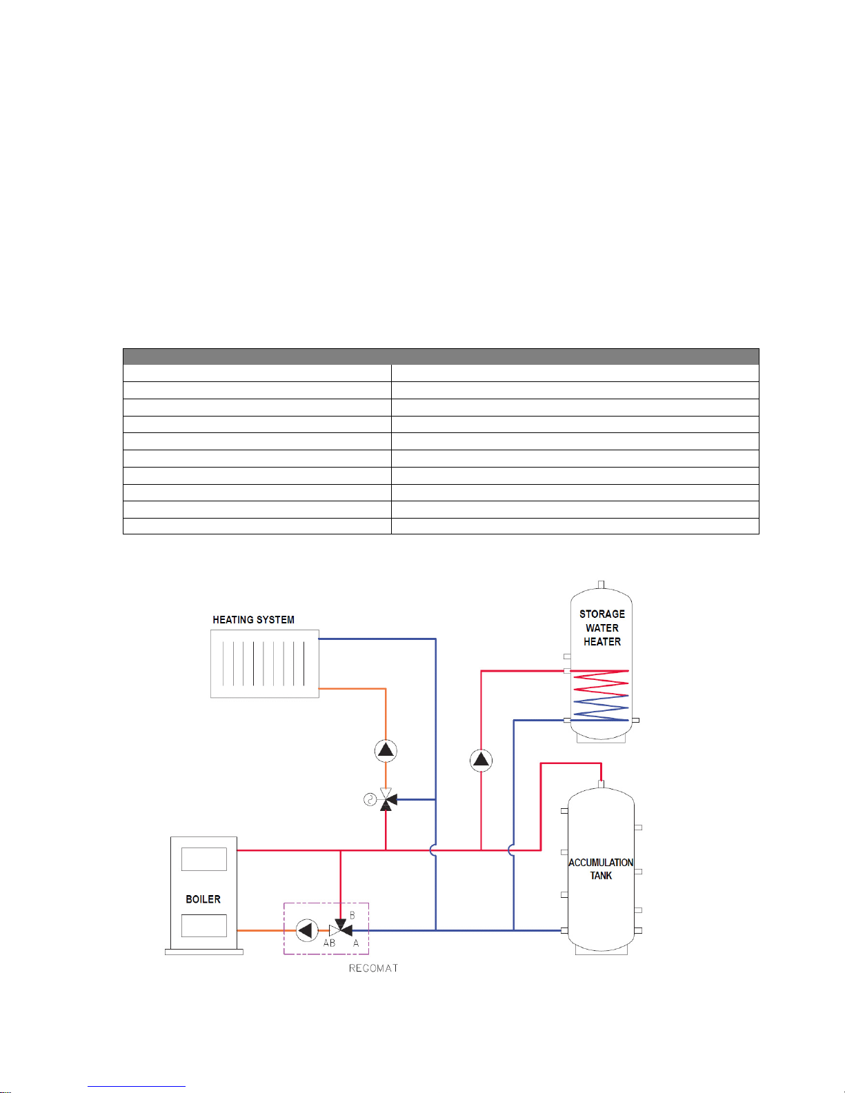
3. Connection diagram
Page 3
4. Possible installation positions with a boiler
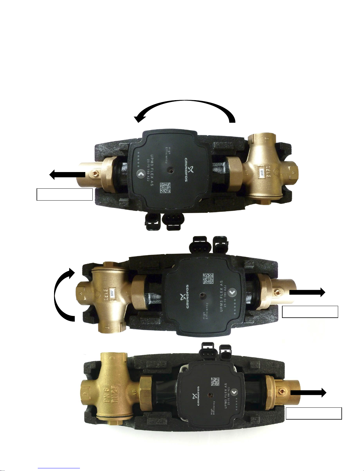
This pump station comes in the version for horizontal installation on the left
side of a boiler. However, it can be installed also into a vertical piping or on the
right side of a boiler. When being installed horizontally on the right side of a
boiler, the pump station needs to be turned by 180° and the TVS valve turned
as shown in the pics. below.
FLOW DIRECTION
FLOW DIRECTION
FLOW DIRECTION
Page 4
5. Regomat components:
» UPM3 heating system circulation pump, incl. a power cord and control cable
» TSV3B
thermostatic mixing valve (45 °C, 50 °C, 55 °C, 60 °C, 65 °C or 70 °C)
» pump ball valve
» thermometer
» insulation
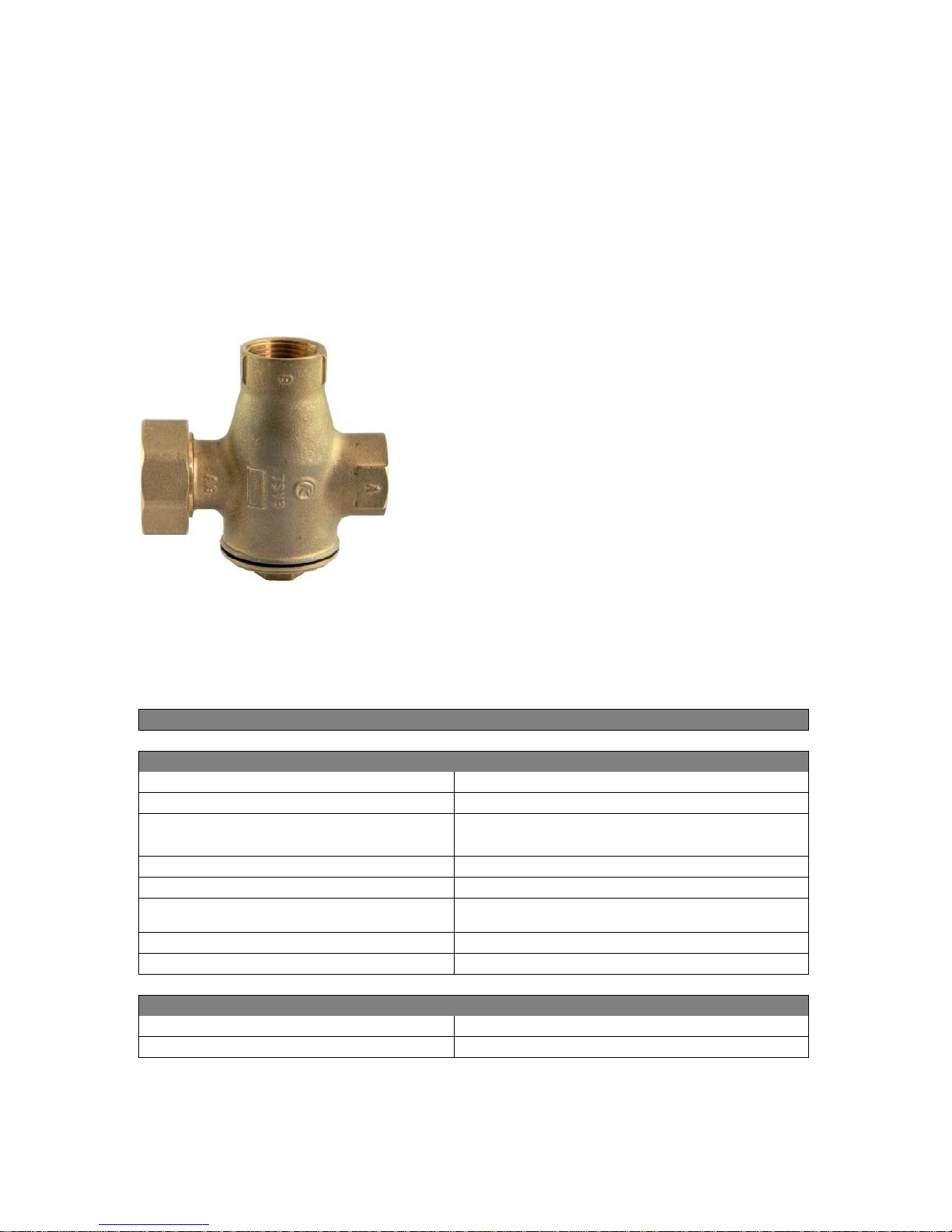
6. Function description of TSV3B valve
TSV B thermostatic mixing valve is fitted with an
integrated thermostatic insert that will close the “A”
inlet (from a heating system), if the return water
temperature to the boiler (“AB” outlet) is lower than
the opening one. As soon as the opening
temperature is reached, the thermostat starts
opening the “A” inlet slowly and mixing the cold
return water with the hot water from the “B” inlet
(boiler outlet) so that the return nominal
temperature (“AB” outlet) is reached. At the same
time, it closes the “B“ inlet, limiting so the hot water
flow coming from the by-pass till its complete tight
closure. Thanks to this, no balancing valve is
needed. The Thermostatic mixing valve is made of
brass, sealing of the element and body plug are
made of EPDM, sealing of closing plug is made of
NBR.
Parameters of SV3B Thermostatic valve
Technical data
Max. operating temperature
95 °C
Max. working pressure
6 bar
Valve opening temperature depending on the element (45, 50, 55, 60, 65, 70 °C)
Control range
t
valve, opening
+ 5 °C
Valve Kvs (A→AB direction)
6.2 m3/h
Valve Kvs (B→AB direction)
4.4 m3/h
Nominal inner diameter
DN25
O-ring under the plug
45x3 mm
Materials
Housing, bonnet and plug
forged brass
Gasket
EPDM
Page 5
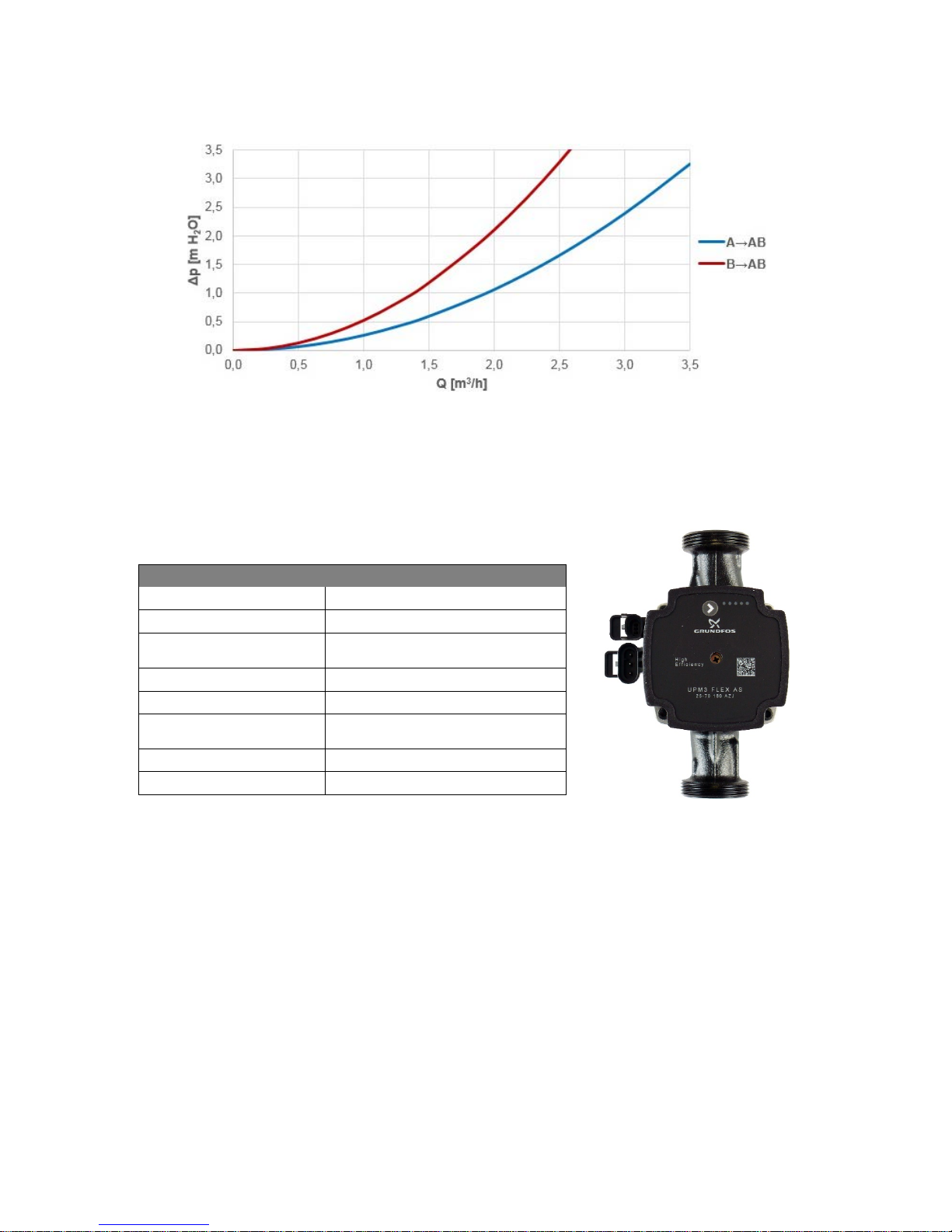
Valve pressure drop diagram
During mixing, the valve pressure drop lies between the two curves, depending on
the mixing ratio.
UPM3 FL
EX AS 25-70 Pump
Design
Wet-running circulation pump with G 6/4” M connection.
Electrical data
Power supply 230 V, 50 Hz
Power input (min./max.)
2/52 W
Current (min./max) 0.04/0.5 A
IP protection IP44
Max. speed 5766 rpm
Weighted average
power
≤ 23 W
Energy Efficiency Index ≤ 0,2 by EN 16 297/3
Motor protection not needed
Pump control
The pump can be controlled by an external PWM signal (profile for use in heating
systems) or without a PWM signal by selecting a pump performance curve.
A maximum curve of a pump working range can be defined.
- with PWM signal the pump speed changes with the signal value up to the
maximum of the selected curve
- without PWM signal the pump runs at the max. speed according to the
selected curve
Page 6
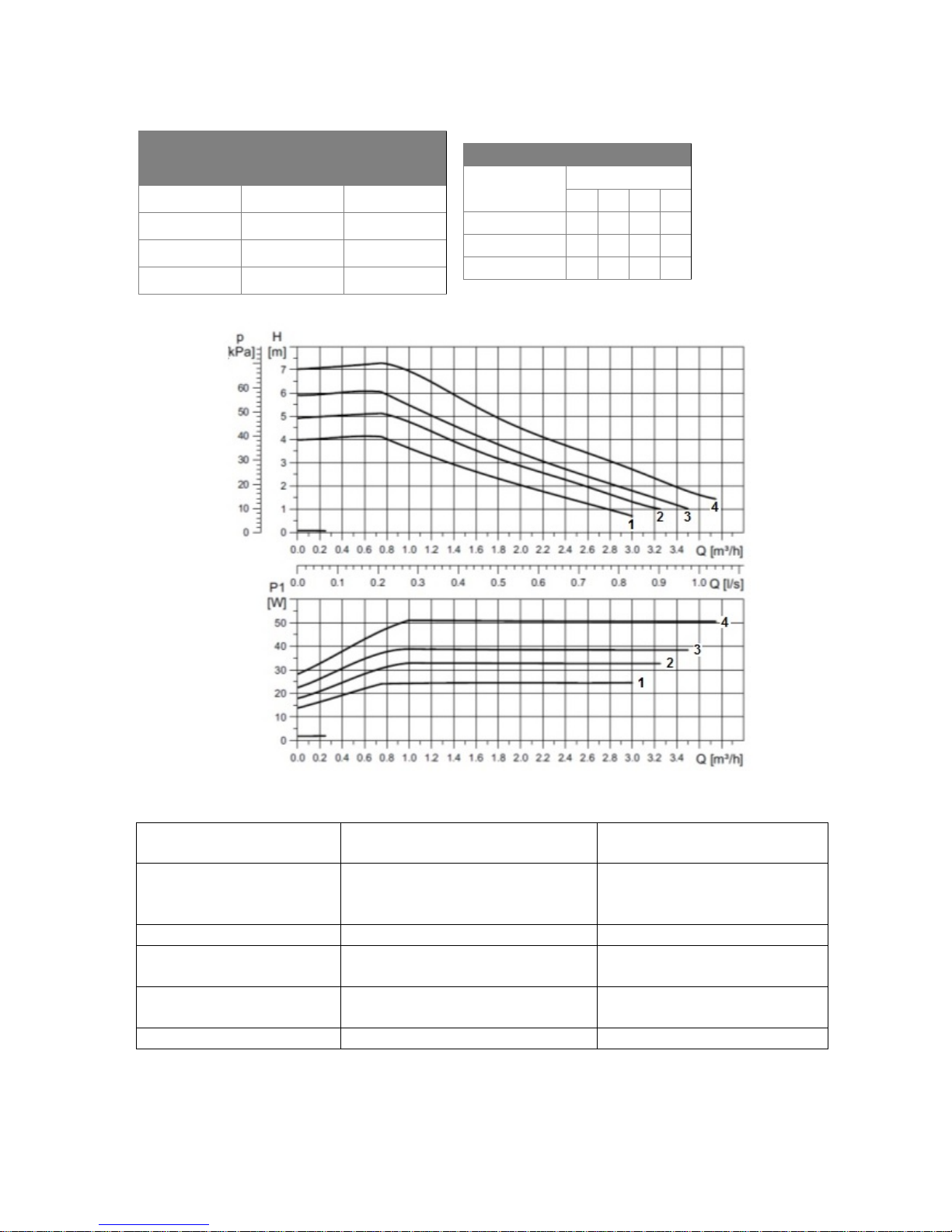
Performance curves
Curve
Max. H
Max. P1
(upper graph)
(lower graph)
1
4 m
25 W 2 5 m
33 W 3 6 m
39 W
4
7 m
52 W
Performance display
DISPLAY
STATE
PERFORMANCE from
P1max in %
1 flashing green LED
STAND-BY MODE
(EXTERNAL CONTROL
ONLY)
0
1 green + 1 yellow LED
LOW PERFORMANCE
0-25
1 green + 2 yellow LED
MEDIUM-LOW
PERFORMANCE
25-50
1 green + 3 yellow LED
MEDIUM-HIGH
PERFORMANCE
50-75
1 green + 4 yellow LED
HIGH PERFORMANCE
75-100
When switched on, the pump runs at factory settings or the last setting. The display
shows the momentary pump performance.
MAX. BOILER OUTPUT [kW]
t
valve, openi ng
Curve
1 2 3 4
45 °C
37 41 43 48
55 °C
29 32 34 37
65 °C
21 23 24 27
Page 7
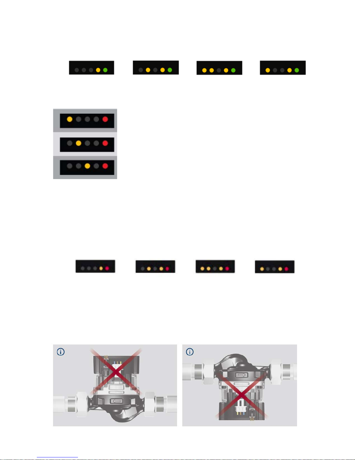
seized pump
too low power supply voltage
electric fault
Setting selection for UPM3
1. Pr
ess the pushbutton until the LEDs start flashing, the pump will switch
to adjustment selection mode.
2. To select
your desired setting, press the button repeatedly until you find the setting
you need, see the pics below. If you pass the desired setting, you have to go one
more round until it appears again – there is no way back in the loop.
4 m 5 m 6 m 7 m
3. Release the button for more than 10 s and the LEDs will return to “performance
view”, while the last setting is saved.
Forbidden pump positions
Settings display
WARNING: LEDs may be turned by 180°, depending on the specific pump type.
By
pressing the button the display switches to “performance view” and the current
settings will be shown by LEDs for 2 seconds.
5 m
6 m
7 m
4 m
Error display
Page 8
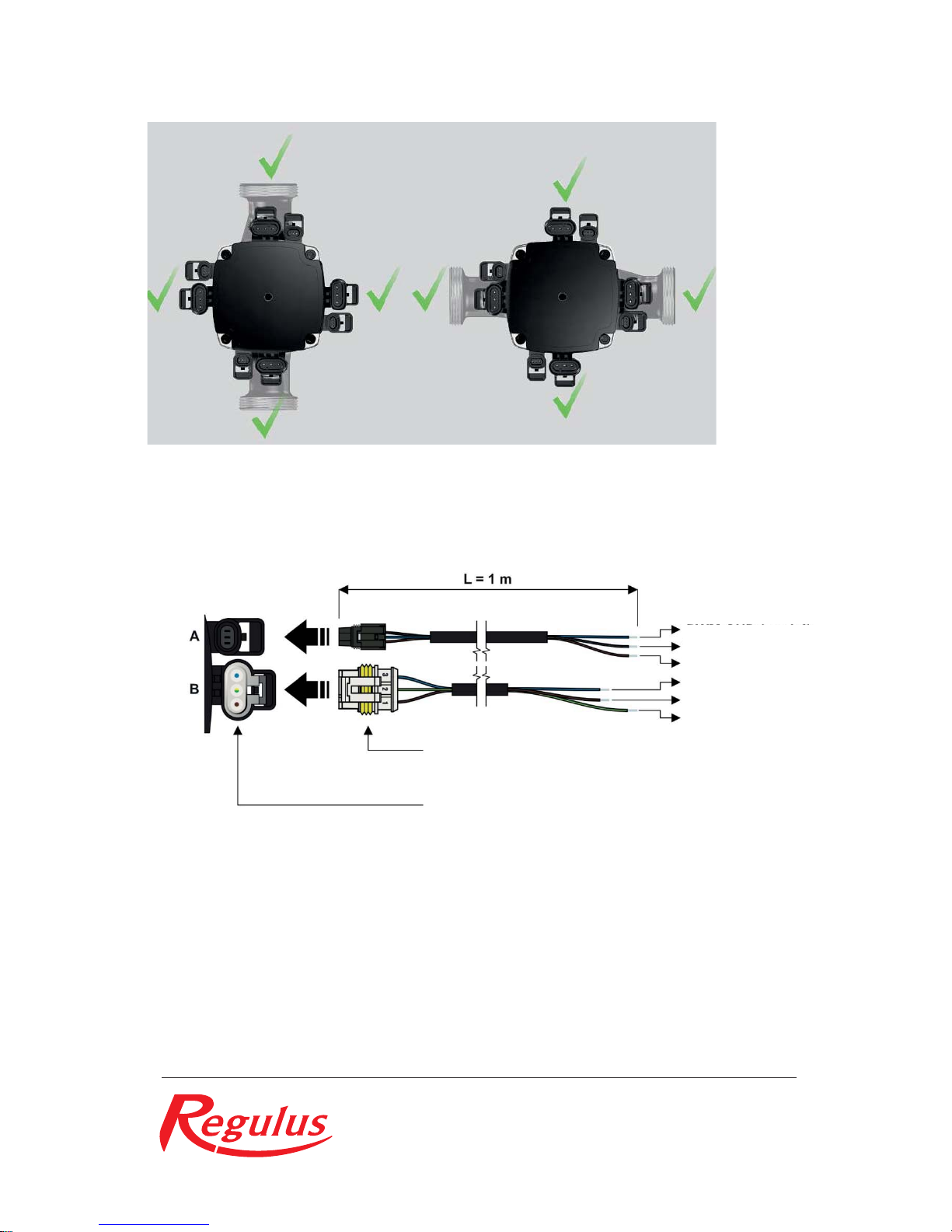
Permissible pump (actuator) positions
Pump wiring
PWM GND (blue)
PWM out (black)
PWM in (brown)
N (blue)
L (brown)
PE (yellow-green)
signal and power
supply terminals
socket for signal
transmission (A)
and power supply (B)
11/2016
REGULUS spol. s r.o.
 Loading...