

Page 1
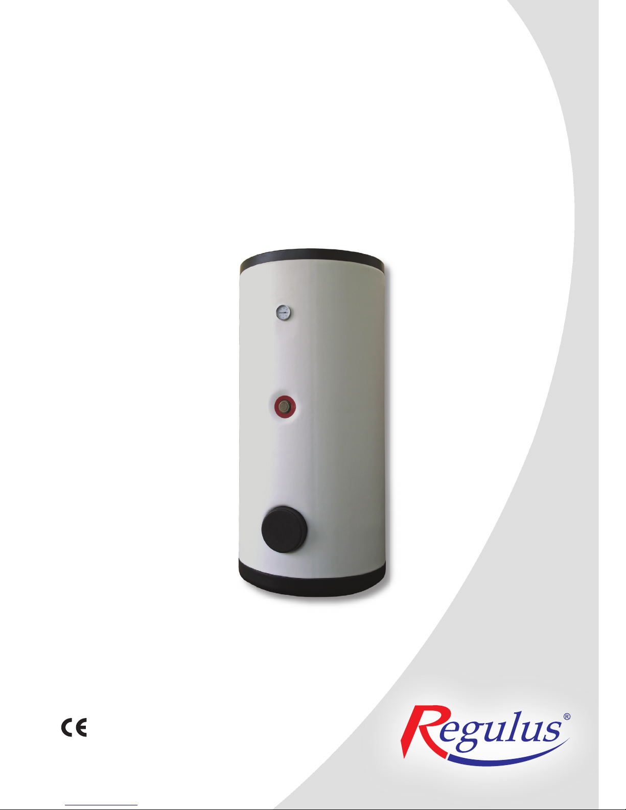
R2GC 200, R2GC 250, R2GC 300, R2GC 400
STORAGE WATER HEATERS
EN
v. 1.1
Users Manual
Date of manufacture: ...................................
Serial number: .............................................
Checked by: ................................................
Page 2

│
2
EGULUS - R2GC storage water heaters - www.regulus
.
CONTENTS
1 Description ......................................................................................................................................... 3
1.1 Model line ............................................................................................................................. 3
1.2 Tank protection ..................................................................................................................... 3
1.3 Thermal insulation ................................................................................................................ 3
1.4 Connection points ................................................................................................................ 3
1.5 Packing ................................................................................................................................ 3
2 General Information ........................................................................................................................... 3
3 Technical Data and Dimensions of R2GC Tanks ............................................................................. 4
4 Operation ............................................................................................................................................ 5
5 Examples of Assigning Connection Points ..................................................................................... 5
6 Installation and Commissioning ....................................................................................................... 7
6.1 Connection to heat sources ................................................................................................. 7
6.2 Connection to a solar system ............................................................................................... 7
6.3 Heating rod installation ......................................................................................................... 7
6.4 Connection to water mains ................................................................................................... 7
6.5 Electronic anode installation ................................................................................................ 7
6.6 Commissioning ..................................................................................................................... 8
7 Maintenance, Replacement of Magnesium Anode Bar ................................................................... 8
8 Disposal .............................................................................................................................................. 8
9 Warranty .............................................................................................................................................. 8
Page 3

3
│
EGULUS -
2GC storage water heaters - www.regulus.
1 - Description
R2GC storage water heater (“tank” further on) is designed to accumulate heat for domestic hot water (DHW).
The tank is heated from hot-water heat exchangers installed inside (2 heating coils). The lower heating coil
can be used to connect e.g. a solar system while the upper heating coil can be fed from e.g. a gas-fired boiler
or an accumulation tank. The speed of heating up the tank to the desired temperature depends primarily on
the fluid temperature entering the heat exchanger. Higher temperatures of the incoming fluid mean quicker
heating up the tank, and vice versa. Should the output of the heat exchanger be insufficient for some applications, an electric heating rod can be installed into the tank.
The entire hydraulics of a heating system shall be designed properly in order to achieve flawless operation of
the tank, i.e. the position of circulation pumps for heat sources and heating circuits, valves, check valves etc.
1.1 - Model line
These storage water heaters are supplied in four sizes: 200, 250, 300 and 400 l.
1.2 - Tank protection
The tank body is made of sheet steel, finished outside with durable ecologic powder coating. Its inner enamel
lining works as anticorrosion protection and together with a magnesium anode rod it guarantees a long service life. The magnesium anode rod shall be inspected regularly - see point 7. Maintenance, Replacement of
Magnesium Anode Rod. An electronic anode can be also used; its lifetime covers the lifetime of the tank if its
operation indicator works right.
1.3 - Thermal insulation
Tanks are insulated with ecologic 55 mm PUR foam (50 mm for R2GC 400) that reduces thermal loss to minimum.
1.4 - Connection points
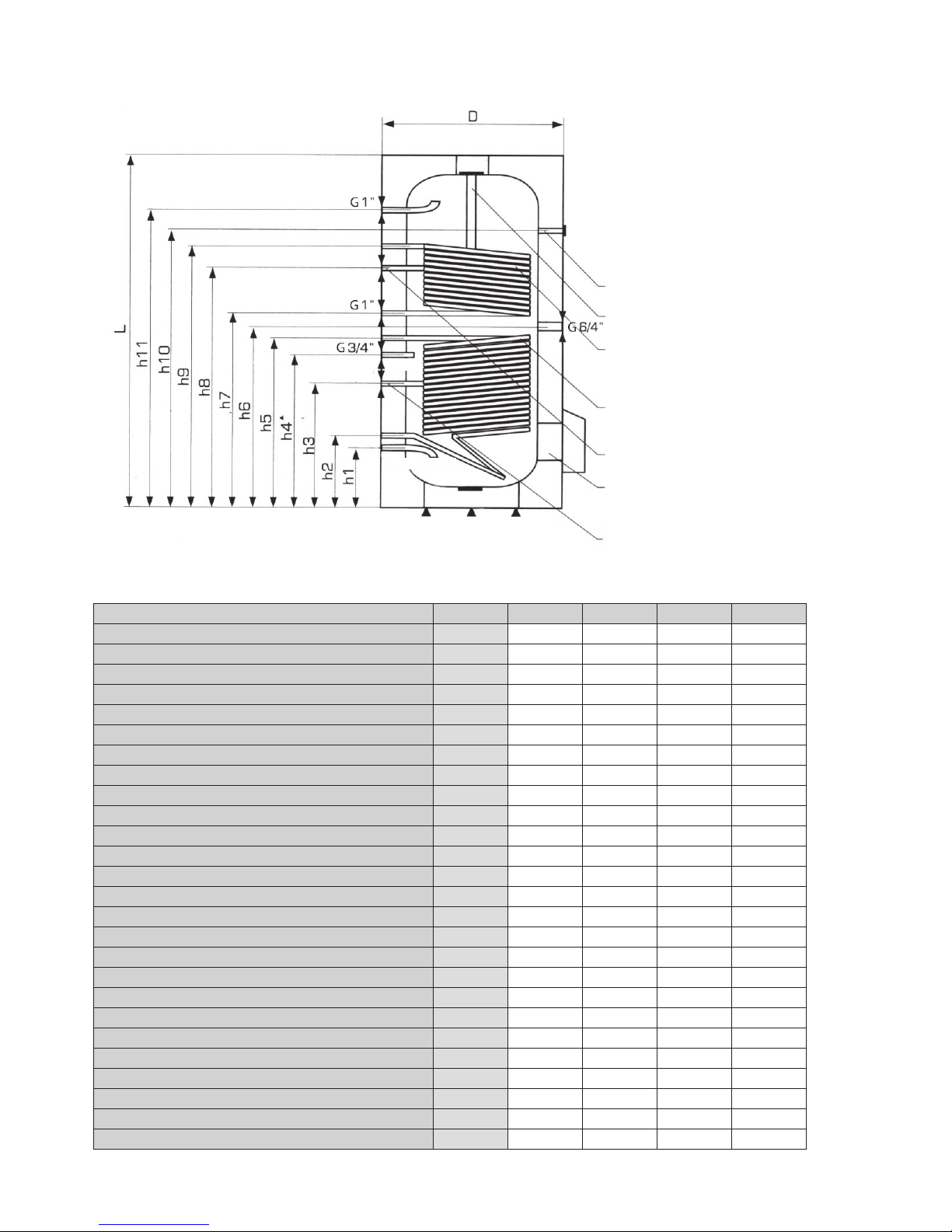
4× lateral, G 1“ female thread, for heating coils
2× lateral, G 1“ female thread, cold water in, hot water out
2× lateral, G 1/2“ female thread, for temperature probes
1× lateral, G 3/4“ female thread, for recirculation
1× upper, G 5/4“, for magnesium anode rod
1× lateral, G 6/4“ female thread, for electric heating rod
1× lateral, G 1/2“ female thread, for thermometer
1.5 - Packing
Tanks are delivered standing, each screwed to its pallet, shrink-wrapped. It is forbidden to transport and/or
store the storage tanks in a horizontal position.
2 - General Info
The appliance shall be installed by a qualified person according to valid rules.
This Users Manual is an integral and important part of the product and must be handed over to the User. Read
carefully the instructions in this Manual as they contain important information concerning safety, installation,
operation and maintenance. Keep this Manual for later reference.
Using the storage water heater for other purposes than above described is forbidden and the manufacturer
accepts no responsibility for damage caused by improper or wrong use.
Page 4
│
4
EGULUS - R2GC storage water heaters - www.regulus
.
3 - Technical Data and Dimensions of R2GC Tanks
Units R2GC 200 R2GC 250 R2GC 300 R2GC 400
Volume [l] 200 250 300 400
Cold water inlet max. pressure [MPa] 0.6 0.6 0.6 0.6
Max. working temperature [°C] 100 100 100 100
Lower heating coil surface [m
2
] 1 1.2 1.4 1.8
Lower heating coil volume [l] 5.5 6.6 8.6 11.5
DHW heating Δt=35 °C (80/60 - 10/45) - lower heating coil [kW] 34.6 41.5 48.5 62.3
Flow rate [l/h] 850 1020 1190 1540
Upper heating coil surface [m
2
] 0.7 1.0 1.1 1.3
Upper heating coil volume [l] 4.5 5.5 6.4 7.4
DHW heating Δt=35 °C (80/60 - 10/45) - upper heating coil [kW] 24.2 34.6 38.1 45
Flow rate [l/h] 600 850 940 1110
Heating water needed [m3/h] 2.7 2.85 3.0 3.0
h1 [mm] 210 130 210 240
h2 [mm] 290 210 290 320
h3 [mm] 400 355 440 570
h4 [mm] 570 520 580 770
h5 [mm] 500 620 760 870
h6 [mm] 570 680 780 900
h7 [mm] 640 740 845 980
h8 [mm] 710 910 1015 1150
h9 [mm] 820 1080 1090 1330
h10 [mm] 830 1010 1170 1310
h11 [mm] 900 1170 1260 1410
L [mm] 1140 1300 1450 1660
D [mm] 660 660 660 700
Weight [kg] 98 122 133 162
G 1/2“ thermometer
Magnesium anode rod
For heating rod installation
Upper heating coil
Lower heating coil
Upper heating coil sensor sheath
Inspection hole
Lower heating coil sensor sheath
Openings for a heating rod and thermometer are located opposite the other ones.
G 5/4“
G 1“
G 1“
G 1“
ø 17×2
G 1“
ø 17×2
Hot water
Cold water
Circulation
Page 5
5
│
EGULUS -
2GC storage water heaters - www.regulus.
4 - Operation
This tank is designed for operation in pressure circuits. Water can be heated inside in its heat exchangers
(heating coils) from several heat sources, e.g. various hot-water boilers, renewable energy sources (heat
pumps, solar collectors). An electric heating rod can be installed to backup DHW as well.
DHW temperature inside the tank shall be kept between 60 and 65 °C. This temperature guarantees optimum
operation and the best protection against Legionella bacteria.
5 - Examples of Assigning Connection Points
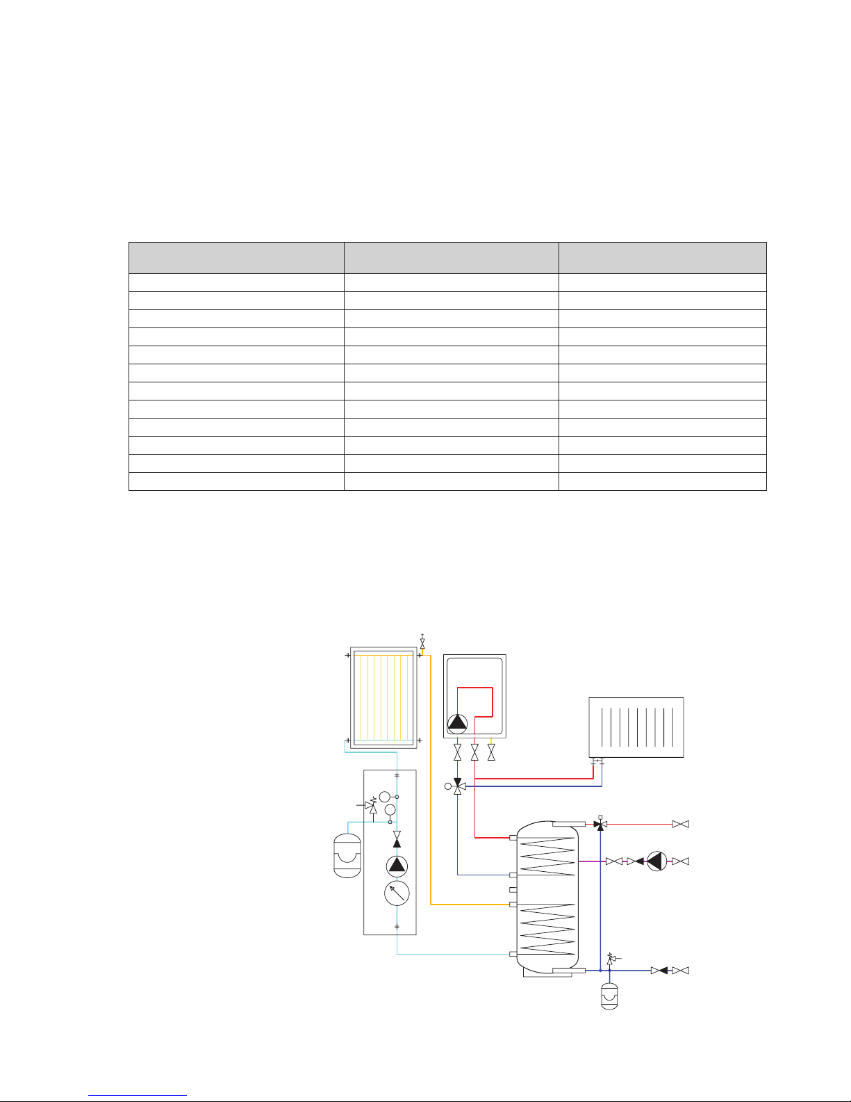
Example I.
With a gas boiler and solar system.
R2GC
HW
CW
recirculation
E
E
gas
boiler
T
bbbbbbb
bbb
B
bbb
bbb
Conn. point
Example I.
with a gas boiler
Example II.
with a boiler and accum. tank
G 5/4“ upper flange magnesium anode magnesium anode
G 1/2“ thermometer thermometer thermometer
G 6/4“ plug electric heating rod
h1 cold water inlet cold water inlet
h2 outlet into a solar system outlet into a solar system
h3 temperature probe, thermostat temperature probe, thermostat
h5 inlet from a solar system inlet from a solar system
h7 return to a gas boiler return to an accum. tank
h8 temperature probe, thermostat temperature probe, thermostat
h4 circulation circulation
h9 inlet from a gas boiler inlet from an accum. tank
h11 hot water outlet hot water outlet
Connections depend on the circuit to be connected, the a.m. examples are informative only.
Page 6
│
6
EGULUS - R2GC storage water heaters - www.regulus
.
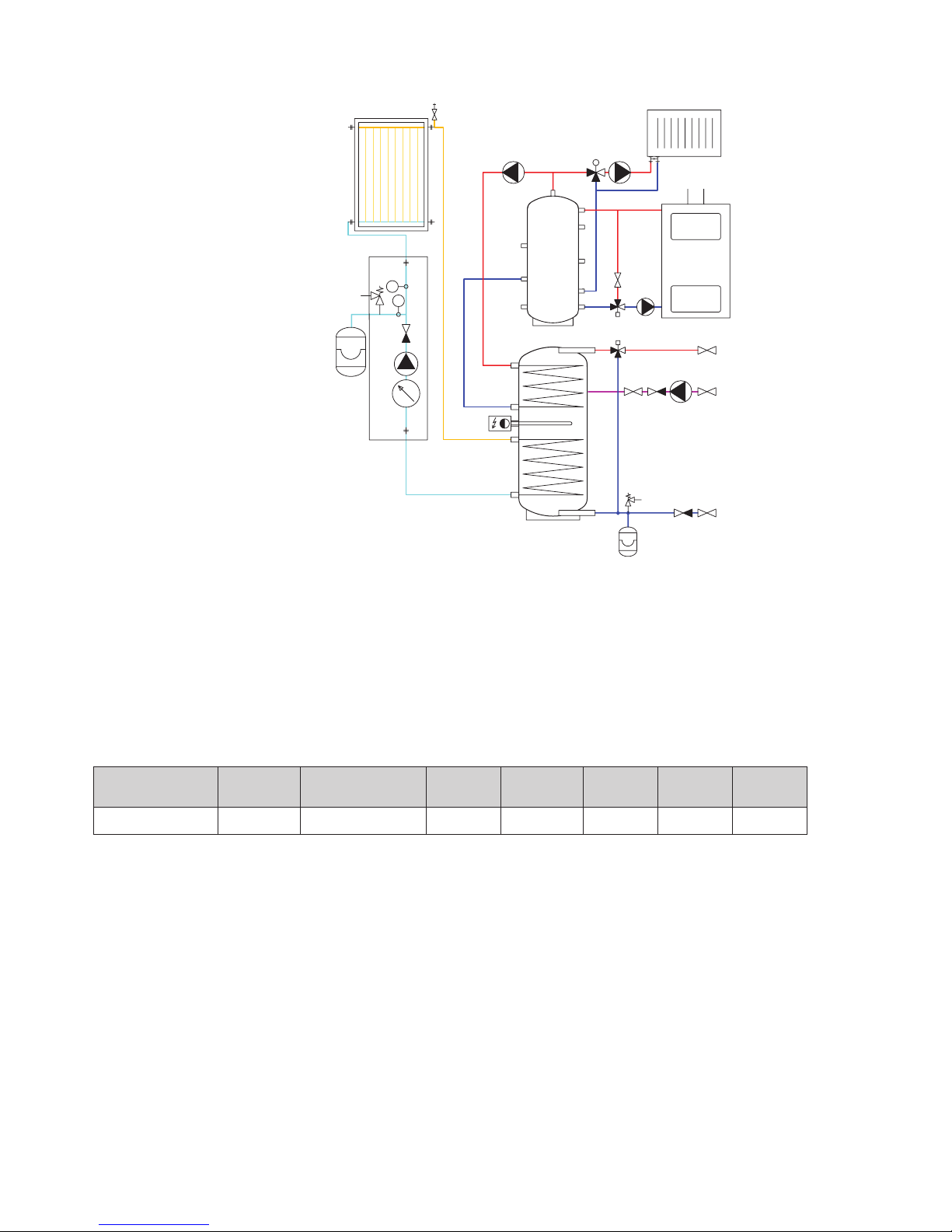
Example II.
With a solid fuel boiler, solar system and accumulation tank.
boiler
PS
R2GC
HW
CW
recirculation
E
E
T
bbbbbbb
bbb
B
bbb
bbb
Table of limit values for total dissolved solids in hot water
Description pH Total dissolved
solids (TDS)
Ca Chlorides Mg Na Fe
Max. value 6.5 - 9.5 600 mg/l 40 mg/l 100 mg/l 20 mg/l 200 mg/l 0,2 mg/l
Page 7

7
│
EGULUS -
2GC storage water heaters - www.regulus.
6 - Installation and Commissioning
Installation must meet valid rules and may be done only by qualified staff. The tank shall be placed on the
floor, as close to the heat source as possible.
Warning: Defects caused by improper installation, use or handling are not covered by warranty.
6.1 - Connection to heat sources
Connect heating circuits to the inlets to and outlets from heating coils. The heat source for the tank - 2 enameled coils - connects with G 1” coupling.
6.2 - Connection to a solar system
The tank can be used with a solar system. In such a case, the inlet for hot heat-carrying liquid coming from the
solar system shall be connected to the G 1” upper sleeve of the lower heating coil and the lower outlet to the
return piping to the solar system. Insulate all the piping between the tank and the solar system.
6.3 - Heating rod installation
The G 6/4“ side sleeve is designed to accommodate an electric heating rod. Heating rods of output up to 6 kW
can be used (depending on the tank diameter and rod length), connected either directly to the mains (thermostat-equipped rods), or to a heating system controller. The installation may be done by qualified staff only.
Warning: Electric heating elements shall be protected by a safety thermostat.
6.4 - Connection to water mains
DHW piping shall be done according to valid rules. G 1” threaded couplers are used to connect the tank to
a cold water inlet and hot water outlet. A 6bar safety valve shall be installed at the cold water inlet, installation of a reducing valve is recommended. If the pressure from water mains exceeds 6 bar, a reducing valve is
necessary. In order to prevent water loss, an expansion tank should be installed at the cold water inlet as well
(8l volume for R2GC 200, 250 and 12l volume for R2GC 300 and 400).
Should the water be too hard, install a water softener before the tank. In case the water contains mechanical
impurities, install a strainer.
A suitable thermostatic mixing valve should be installed at the hot-water outlet from the tank, preventing too
hot water from entering the taps.
Install a drain valve to the lowest point of the tank.
Complete DHW piping shall be properly insulated.
6.5 - Electronic anode rod installation
So called electronic anode can be used instead of the magnesium one. Its principle advantage is that its
proper function is signaled by a control lamp while a magnesium anode rod needs to be taken out for check. In
such a case, just visual check of the electronic anode is sufficient.
Please use a G 5/4” to G ½” reducing coupler when installing an electronic anode. In order to protect the tank
properly and meet its warranty conditions, select an anode from the table below. A space of about 0.5 m is
needed between the tank top and ceiling to install/exchange the electronic anode rod (0.35 m for R2GC200).
Kit for R2GC storage water heaters
Code Anode rod length [mm] For storage water heaters
9176 350 (200/150) R2GC 200
9177 500 (350/150) R2GC 250, R2GC 300, R2GC 400
Page 8

/20
REGULUS spol. s r.o.
│
8
EGULUS - R2GC storage water heaters - www.regulus
.
6.6 - Commissioning
Fill the heating circuits with the appropriate fluids and air-bleed the entire system. Check all connections for
leaks and verify the system pressure.
The quality of top-up and heating water is set by ČSN 07 7401:1992. Hot water quality must meet the con-
ditions shown in the Table of limit values for total dissolved solids in hot water, page 6 of this Manual.
Fill the heating circuits with the appropriate fluids and air-bleed the entire system. Check all connections for
leaks and verify the system pressure. Set the heating controller in compliance with the documentation and
manufacturer’s recommendations. Check regularly a proper function of all control and adjusting elements.
7 - Maintenance, Replacement of Magnesium Anode Rod
If the tank is fitted with a heating element, disconnect it from the mains first.
Clean the exterior of the tank with a soft cloth and a mild detergent. Never use abrasive cleaners or solvents.
Check all connection for leaks.
The tanks are equipped with an anti-corrosion sacrifice magnesium anode rod. The anode rod shall be
checked within 6 months after commissioning and subsequently always not later than 6 months after the last
check. If more than 1/3 of its total volume is consumed, the anode shall be replaced with a new one. Disregarded of its state, the anode rod shall be replaced with a new one within 24 months from commissioning.
In case an electronic anode is used, the above described procedures are not necessary. Then only a visual
check of the indication lamp is necessary every 3 months.
Proper working of the Electronic Anode is described in its User’s Manual.
If damage to a tank occurs due to neglected substitution of a magnesium anode rod or a non-working electronic anode, the warranty cannot be claimed.
8 - Disposal
Packing shall be disposed of in compliance with the valid rules. When the product reaches the end of its life, it
shall not be disposed of as household waste. It shall be dropped off at a Local Waste Recycling Center. Insulation shall be recycled as plastic and the steel vessel as scrap iron.
9 - Warranty
This product is covered by warranty according to the conditions described in this Manual and according to the
Warranty Certificate. A Warranty Certificate is an integral part of the supply. Tank transport or storing in a hori-
zontal position is considered a warranty violation!
 Loading...