

Regulus PS2F 1000 N+, PS2F 300 N+, PS2F 1500 N+, PS2F 2000 N+, PS2F 3000 N25 Installation And Operation Manual
...
www.regulus.cz
PS2F N+
PS2F N+
Installation and Operation Manual
THERMAL STORES
PS2F 300 N+, PS2F 500 N+, PS2F 800 N+,
PS2F 1000 N+, PS2F 1500 N+ and PS2F 2000 N+
EN

CONTENTS
1 Description ..................................................................................................................................................... 3
1.1 Models ................................................................................................................................................ 3
1.2 Tank protection ................................................................................................................................... 3
1.3 Thermal insulation .............................................................................................................................. 3
1.4 Connection points on the tank ........................................................................................................... 3
1.5 Packing ............................ ................................................................................................................. 3
2 General Information ....................................................................................................................................... 3
3 Technical Data and Dimensions ................................................................................................................... 4
4 Operation ........................................................................................................................................................ 5
5 Examples of ports allocation ........................................................................................................................ 5
6 Installation and Commissioning ................................................................................................................... 7
7 Installing Insulation on the Tank .................................................................................................................. 8
8 Maintenance ................................................................................................................................................... 10
9 Disposal .......................................................................................................................................................... 10
10 Warranty .......................................................................................................................................................... 10
2
│

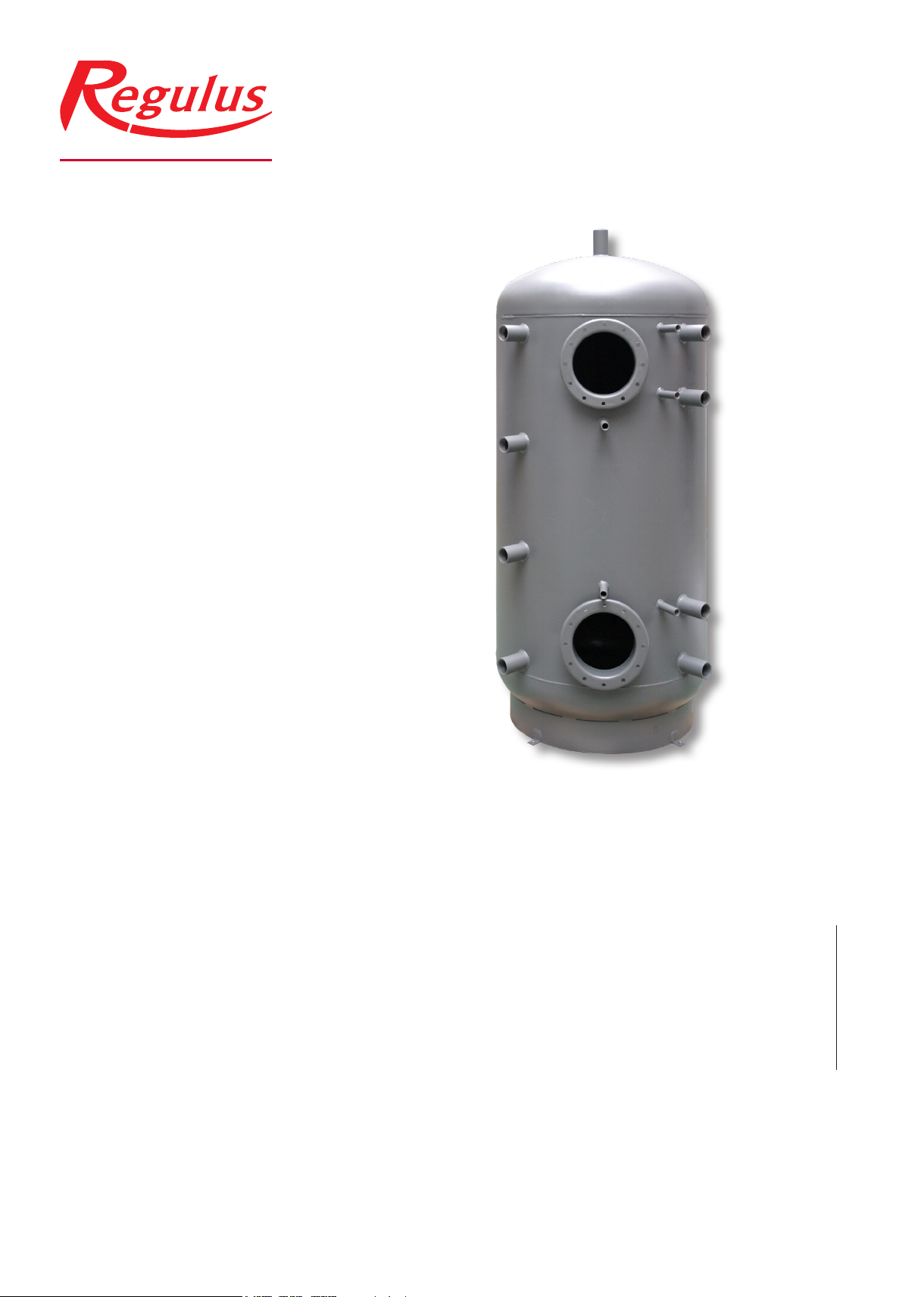
1 - Description
PSWF N+ Thermal Stores are intended for storing and subsequent distribution of thermal energy from solid-fuel red
boilers, heat pumps, solar collectors, electric boilers etc. This thermal store shall be always connected to a sealed
heating circuit. It is tted with two anges ready to receive suitably sized tube heat exchangers. Mating anges for
heat exchangers with either G 1” or G ¾” connections are available as an option. When no heat exchanger is installed, a blind ange shall be used (option).
These heat exchangers are made of nned copper tubes that feature larger surface area and better heat transfer.
The lower heat exchanger usually connects to a solar system and the upper one is used for DHW heating (continuous) which limits signicantly the risk of Legionella bacteria formation. The tanks are also tted with nine G 6/4“ side
sleeves to connect heat sources, four G ½“ ones for sensor sheaths and one G ½“ sleeve for a safety valve. El. heating elements can be installed directly into the 6/4” sleeves.
1.1 - Models
Six models of 285, 479, 809, 932, 1509 and 2010 l capacity.
1.2 - Tank protection
The inner surface has no nish, no anticorrosion protection, the outer surface is lacquered in gray.
1.3 - Thermal insulation
Tank insulation is available as a separate item, installed on the tank on the spot for easier handling.The insulation is
made of 100 mm thick eece and tted with a zippered outer layer in PU leather.
1.4 - Connection points on the tank
2 anges with 210 mm inner diam.
8 side sleeves in a 90° sector, G 6/4” F thread
1 top sleeve, G 6/4” F thread
4 side sleeves for sensor sheaths, G ½” F thread
1 side sleeve for a 3 bar safety valve (included), G ½” F thread
1.5 - Packing
Tanks are delivered standing, each screwed to its pallet, packed in bubble wrap.
Included in the package are gaskets, bolts for the ange and a 3 bar safety valve with G ½” F thread.
2 - General Information
This Owners Manual is an integral and important part of the product and must be handed over to the User. Read carefully the instructions in this Manual as they contain important information concerning safety, installation, operation and
maintenance. Keep this Manual for later reference. The appliance shall be installed by a qualied person according to
valid rules and Manufacturer‘s Instructions.
This appliance is designed to accumulate heating water and distribute it subsequently. It shall be connected to a
heating system and heat sources. The equipment is suitable also for continuous water heating. In such a case, the
customer needs to buy a suitably sized heat exchanger (available as accessory) and have it installed into the upper
ange.
Using the thermal store for other purposes than above described (e.g. as a DHW tank) is forbidden and the
manufacturer accepts no responsibility for damage caused by improper or wrong use.
The thermal store shall not be used as a DHW tank!
3
│
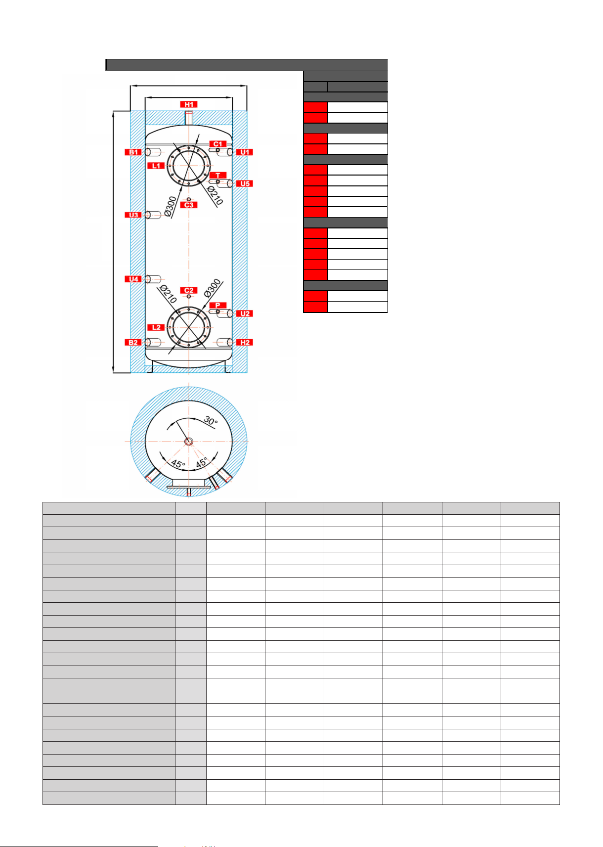
3 - Technical Data and Dimensions
Dimensions
ØD1
ØD
H1
TAPPINGS
pos. connection
Heat sources
B1
B2
Heating system
H1
H2
Control and safety
C1
C2
C3
T
P
Universal inlet / outlet
U1
U2
U3
U4
U5
Flanges
L1
L2
G 6/4" F
G 6/4" F
G 6/4" F
G 6/4" F
G 1/2" F
G 1/2" F
G 1/2" F
G 1/2" F
G 1/2" F
G 6/4" F
G 6/4" F
G 6/4" F
G 6/4" F
G 6/4" F
12 x M12
12 x M12
Type - model
Tank code
Insulation code
Total uid volume in tank [l]
Empty weight [kg]
Tipping height without insulation [mm]
Dimensions [mm]
4
│
Tank code: ....................................................................................... a
Insulation code: ............................................................................... b
Total uid volume in tank: ................................................................ c
Max. working temperature in tank: .................................................. 95 °C
Max. working pressure in tank PS2F 300 N+ ÷ PS2F 1000 N+: ..... 4 bar
Max. working pressure in tank PS2F 1500 N+ ÷ PS2F 2000 N+: ... 3 bar
Empty weight: ................................................................................. d
Tipping height without insulation: .................................................... V1
PS2F 300 N+ PS2F 500 N+ PS2F 800 N+ PS2F 1000 N+ PS2F 1500 N+ PS2F 2000 N+
a 14726 14729 15218 15221 15224 15227
b 16357 16358 16359 16360 16361 16362
c 285 479 809 932 1509 2010
d 58 78 105 116 182 216
V1 1430 1950 1895 2120 1965 2050
ø D1 750 800 1000 1000 1300 1450
ø D 550 600 800 800 1100 1250
B1 1120 1615 1455 1690 1475 1510
B2 220 225 315 300 335 370
H1 1405 1915 1845 2080 1885 1955
H2 220 225 315 300 335 370
C1 1135 1630 1470 1705 1490 1525
C2 520 560 605 635 625 660
C3 830 1270 1155 1345 1175 1210
T 895 1400 1250 1475 1270 1305
P 450 450 530 525 550 585
U1 1120 1615 1455 1690 1475 1510
U2 360 435 515 510 535 570
U3 795 1155 1075 1230 1095 1130
U4 520 685 695 760 715 750
U5 880 1385 1235 1460 1255 1290
L1 1010 1515 1355 1590 1375 1410
L2 330 335 425 410 445 480
4 - Operation
This thermal store is designed to accumulate heat and heat water for space heating in domestic or industrial applica-
tions, however always in sealed pressure circuits with forced circulation. In the thermal store, heating water is heated
up from several heat sources like various types of hot-water boilers, renewable energy sources (heat pumps, solar
collectors), or electric heating elements.
The thermal store shall be connected to a heat source through G 6/4” threaded ttings. Should it be connected to a
solar system, too, this shall be done through a suitably sized heat exchanger installed into the lower ange.
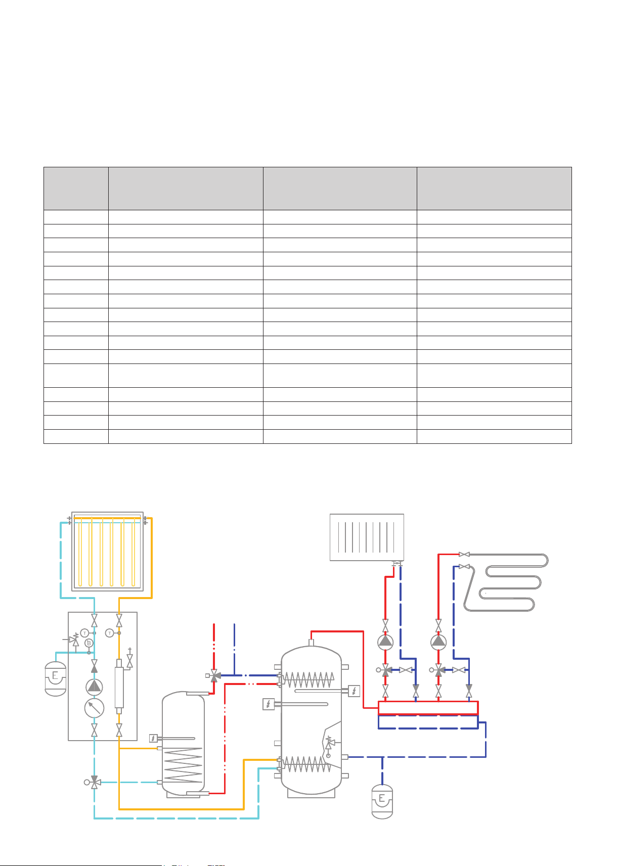
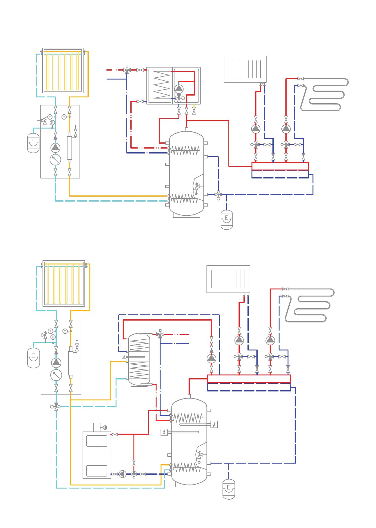
5 - Examples of ports allocation
Conn. point
H1 outlet to heating system outlet to heating system outlet to heating system
B1 plug inlet to boiler (gas-red) inlet from boiler (solid-fuel-red)
U3 el. heating element plug el. heating element
U4 plug plug plug
B2 plug plug outlet to boiler (solid-fuel-red)
H2 drain valve drain valve drain valve
U2 inlet from heating system inlet from heating system inlet from heating system
U5 el. heating element plug el. heating element
U1 plug inlet from heating system plug
P safety valve, G 1/2“, 3 bar safety valve, G 1/2“, 3 bar safety valve, G 1/2“, 3 bar
T thermometer thermometer thermometer
C3 thermostats for heating elements
(adjustable+limit)
C1 sensor for controller with OTC sensor for controller with OTC sensor for controller with OTC
C2 temperature sensor for solar system temperature sensor for solar system temperature sensor for solar system
L1 upper ange heat exchanger for preheating DHW tank heat exchanger for preheating DHW tank heat exchanger for preheating DHW tank
L2 lower ange solar heat exchanger solar heat exchanger solar heat exchanger
Connections depend on the circuit to be connected, the a.m. examples are informative only.
Example I.
Solar collectors
+ el. heating elements
temperature sensor to heating controller thermostats for heating elements
Example II.
Solar collectors
+ gas boiler
Solar collectors + solid fuel boiler +
(adjustable+limit)
Example III.
el. heating elements
Example I.
Solar collectors and el. heating elements.
HW CW
B1
L1
U3
U4
L2
B2
P2
H1
U1
U5
U2
H2
5
│
Example II.
Solar collectors and combi gas boiler.
HW
CW
gas boiler
with DHW tank
B1
H1
U1
L1
U3
U4
L2
B2
Example III.
Solar collectors, solid fuel boiler and el. heating elements.
P2
HW
U5
U2
H2
CW
H1
B1
L1
U1
U5
U3
U4
P2
L2
U2
H2
B2
6
│

6 - Installation and Commissioning
Installation shall meet valid rules and may be done by qualied staff only.
Defects caused by improper installation, use or handling are not covered by warranty.
After the tank is installed and connected to an existing heating system, it is recommended to clean the entire heating
system using a suitable cleaning agent, e.g. MR-501/R.
Anti-corrosion protective liquid should be also used, e.g. MR-501/F or F1.
6.1 - Connection to heat sources
Place the tank on the oor, as close to your heat source as possible. Mount the insulation, cf. Installing Insulation on
the Tank. Connect the heating circuits to inlets and outlets respecting the thermal stratication in the tank. Install a
drain valve at the lowest point of the tank. Install an air vent valve at the highest point of the system. Insulate all the
connecting piping.
6.2 - Connection to a solar system
This tank is suitable for use with a solar system. In such a case a suitably sized heat exchanger shall be installed into
the lower ange. Insulate meticulously all the piping between the tank and the solar system.
6.3 - El. heating element installation
The tank may be tted with electric heating elements up to 12kW output. They can be power-supplied either directly
(elements with built-in thermostat) or via a controller for the entire heating system.
All electric heating elements shall be protected by a safety thermostat.
Electric heating elements shall be installed by an authorized person only.
6.4 - Commissioning
The tank shall be lled up together with the heating system, respecting valid standards and rules. In order to minimize
corrosion, special additives for heating systems should be used. The quality of heating water depends on the quality of
lling water at commissioning, on the top-up water and on the frequency of topping up. This has a strong inuence on the
lifetime of heating systems. Poor quality of heating water may cause problems like corrosion or incrustation, esp. on heat
transfer surfaces.
Fill the heating circuits with the appropriate uids and air-bleed the entire system. Check all connections for leaks and
verify the system pressure. Set the heating controller in compliance with the documentation and manufacturer’s recommendations. Check regularly proper function of all control and adjustment elements.
7
│

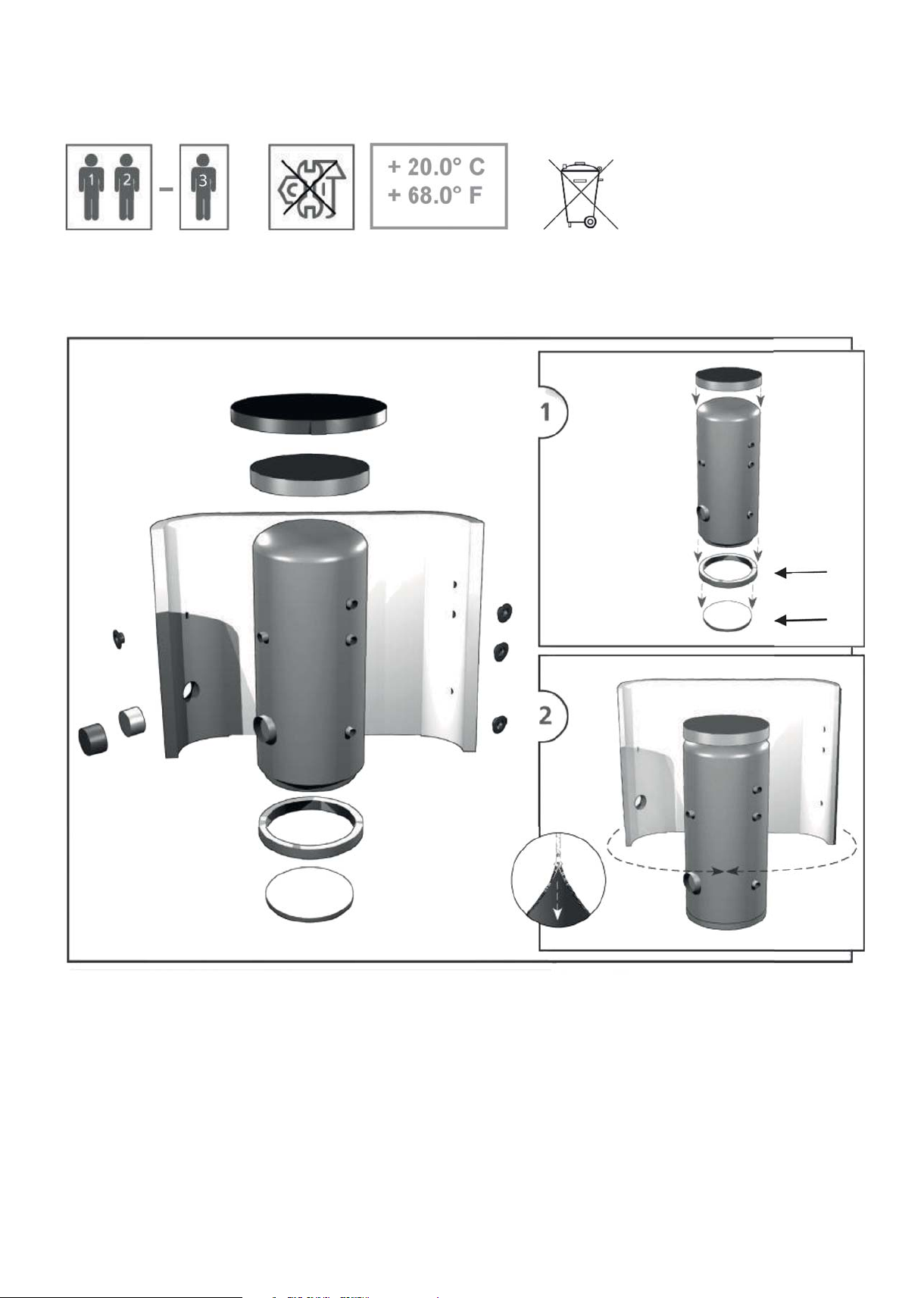
7 - Installing Insulation on the Tank
Instructions
Product description
Fleece thermal insulation with PU leather surface.
Warning
Insulation installation shall be done in two or three persons, depending on its size. The insulation must not be
installed at temperatures below 20 °C. If this cannot be avoided, the insulation shall be pre-warmed in another room
to at least 20 °C. It is impossible to install insulation of lower temperature, there is a risk of damage, esp. to the zipper.
Do not use any tools for installation.
Keep away from open re.
Installing Insulation
1. Fix the tank following installation instructions.
2. Wrap the insulation around the tank carefully. Check that the insulation adheres to its body perfectly. This can be
reached by rubbing and patting the insulation by hand from its center evenly in both directions until the insulation
adheres to the tank’s surface completely and no bubbles are left.
3. Use the holes for sleeves as a rest during the insulation installation.
4. At least one person presses the insulation to the tank, pulling both ends together. The other person closes the zip-
per.
5. Put on the upper insulation and cover.
6. Push on the covering plastic rosettes depending on the size of sleeves, or put on the ange plug(s) with insulation.
7. Finish the tank installation in compliance with the respective instructions and valid standards and rules.
Warranty on insulation
The insulation is covered by a 24-month warranty. This period starts the next day after the insulation is sold.
□ Warranty shall become null and void if:
○ the procedure described in the Installation Manual was not respected,
○ the product was used for other purposes than intended.
□ Warranty does not cover:
○ usual wear and tear,
○ damage caused by re, water, electricity or a natural disaster,
○ defects caused by failure to use the product in compliance with its intended purpose, by improper use and
insufcient maintenance,
○ defects caused by mechanical damage to the product,
○ defects caused by tampering or incompetent repair.
8
│
Návod na instalaci měkké izolace s koženkovým povrchem
Installation instructions for soft insulation with PU leather surface
12/
2015
REGULUS spol. s r.o.
Do Koutů 1897/3 http://www.regulus.cz | http://www.regulus.eu
143 00 Praha 4 E-mail: obchod@regulus.cz | E-mail: sales@regulus.eu
ČESKÁ REPUBLIKA | CZECH REPUBLIC
9
│

8 - Maintenance
If the tank is tted with a heating element, disconnect it from the mains rst. Clean the exterior of the tank with a soft
cloth and a mild detergent. Never use abrasive cleaners or solvents.
Check all connections for leaks.
9 - Disposal
Packing shall be disposed of in compliance with the valid rules. When the product reaches the end of its life, it shall
not be disposed of as household waste. It shall be dropped off at a Local Waste Recycling Center. Insulation shall be
recycled as plastic and the steel vessel as scrap iron.
10 - Warranty
This product is covered by warranty under the conditions listed in this Manual and in compliance with the Warranty
Certicate. A Warranty Certicate is an integral part of this thermal store scope of supply.
10
│

11
│

©2019 We reserve the right to errors, changes and improvements without prior notice.
REGULUS spol. s r.o.
E-mail: sales@regulus.eu
Web: www.regulus.eu
v1.1-06/2019
 Loading...