


- 1 -
-
HR 30W , HR 100 W
Single-Room Heat Recovery V entilation Units
V 1.1
Installation and Operation Manual
EN

- 2 -
1. HR30W and HR100W Heat Recovery Units work under pressure balance, i.e. they supply almost as much air into
a room as they extract.
2. The twin impeller and heat exchanger
arrangement simultaneously supplies and extracts
air while transferring heat from the stale exhaust
airflow to the fresh intake airflow. This provides up
to 70% heat recovery from the stale extracted air.
For situations when the air exchange needs to be
increased immediately, boost mode is available.
3. Installation and maintenance are identical
for both the unit models (HR30W and HR100W)..
CONTENTS
1.0 Introduction .............................................................................................................................. 2
1.1 Description ................................................................................................................. 2
2.0 Installation Conditions ............................................................................................................. 3
3.0 Installation ............................................................................................................................... 4
3.1 Initial preparation ........................................................................................................ 4
3.2 Installing the Appliance ............................................................................................... 5
4.0 Electric Wiring ......................................................................................................................... 6
4.1 Wiring to the mains ..................................................................................................... 6
4.2 Electrical wiring and output switching ......................................................................... 7
5.0 Maintenance ............................................................................................................................ 8
5.1 Cleaning ..................................................................................................................... 8
6.0 EXT 100 Extension .................................................................................................................. 9
1.0 Introduction
1.1 Description
HR30W outside air intake indoor air extraction power input noise level
low speed
boost speed
30 m3/h
40 m3/h
35 m3/h
50 m3/h
10 W
23 W
-
28 dB(A)@3m
HR100W outside air intake indoor air extraction power input noise level
low speed
boost speed
38 m
3
/h
69 m3/h
43 m3/h
77 m3/h
12 W
31 W
20 dB(A)@3m
30 dB(A)@3m
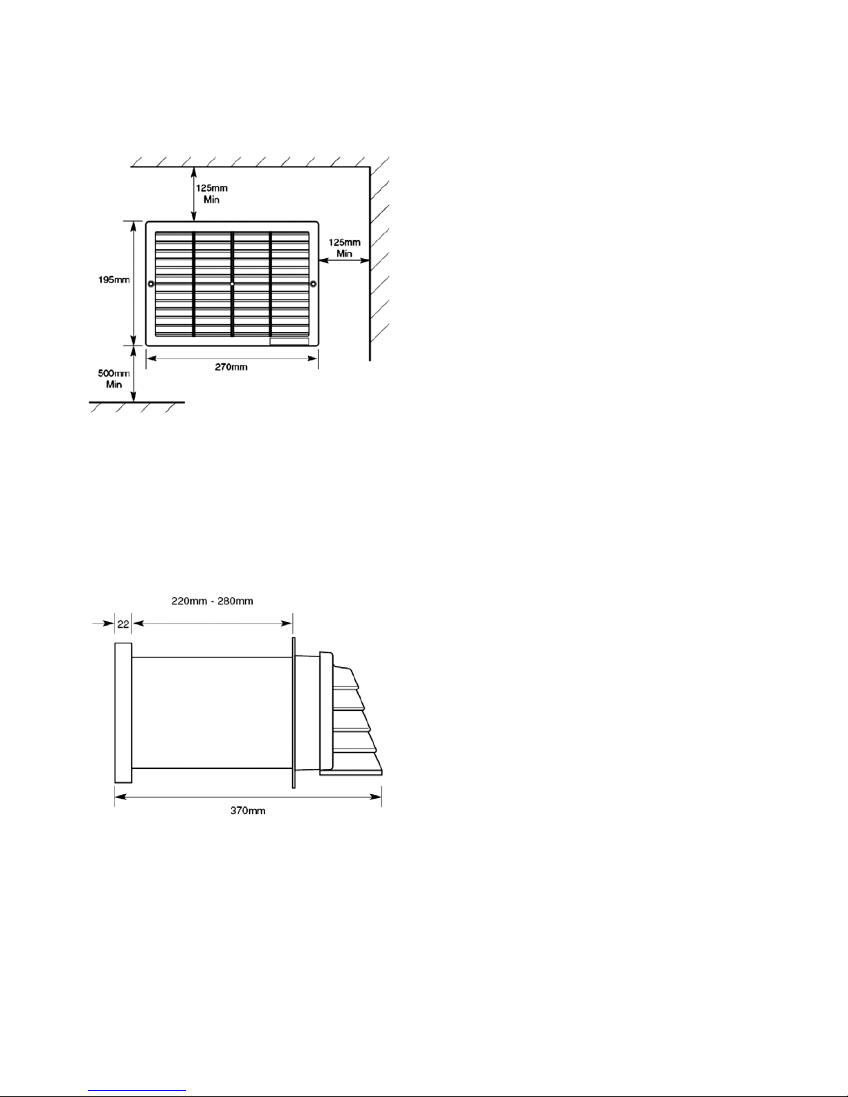
Fig. 1
- 3 -
1. The unit is designed for installation in external walls with a thickness up to 280 mm. For wall thicknesses up to
500 mm an extension kit is available (EXT100).
2. The unit must be located so that the ambient temperature will
not exceed 40° C.
3. Do not install the appliance in the vicinity of excessive levels
of airborne oil or grease.
4. If the unit is installed in a room containing a fuel burning
appliance, sufficient air replacement shall be ensured for both
appliances.
5. The grille frame shall not be located less than 125 mm away
from any wall or projecting surface (Fig. 2).
6. The external grille of the unit must be placed at least
500 mm away from any flue of gas or solid fuel appliances.
This is to avoid back flow of gases entering the room.
7. All safety regulations and requirements must be strictly followed to prevent hazards to life and property both during
and after installation and during subsequent maintenance or servicing.
8. Ensure the mains electrical supply is switched off before commencing installation or maintenance.
2.0 Installation Conditions
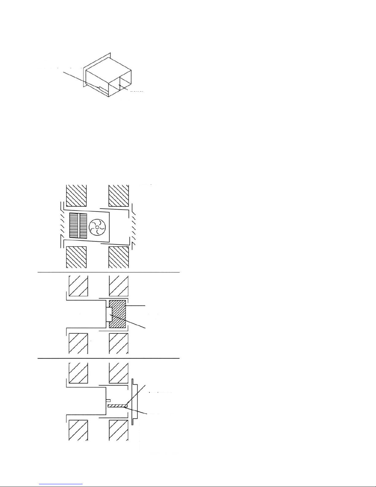
Fig. 2
Fig. 3
adjustable

- 4 -
3.0 Installation
3.1 Initial preparation
1. After considering the site requirements (Section 2.0), select a suitable site for the unit and controllers.
Before deciding on the final position for the unit, check there are no buried cables, pipes or obstructions
in the wall.
Cable requirements:
A 3-core cable for single-speed operation, a 4-core cable for two-speed operation. See wiring.
2. Cut out the template from the rear page of this
Manual. Mark the position of the mounting hole, 240
mm wide and 160 mm high, using this template.
3. Carefully cut the holes in the inner and outer
walls to form a suitable aperture to receive the
unit. Ensure that the unit is positioned with a slight
outward inclination (Fig. 4).
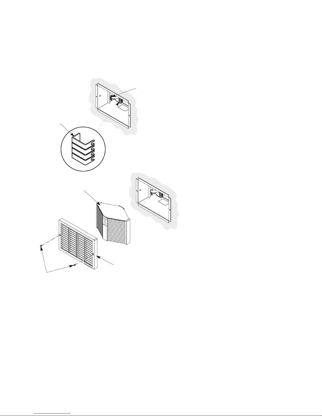
4. Remove the grille, take out heat exchanger, outer
frame and the outer louvre (Fig. 5).
Fig. 4
Fig. 5
louvre
frame
heat exchanger
grille
cable grommet
indoors
angle for
condensate
drain = 1°
outdoors

- 5 -
3.2 Installing the Appliance
From inside
1. Slide the unit into the mounting hole and ensure that the
rear part of the mounting flange is flush with the inner wall
(Fig. 6 and 7).
NOTE: The HR100W and HR30W units require an external
overhang of 60 mm. If this overhang is bigger, the unit shall
be shifted inside until the right overhang is reached.
2. Run the power cable through the grommet (Fig. 6).
3. Ensure that the unit is square and true with the outside
wall face. If firmer fixings are required, secure the unit in
place with the two fixing screws provided (Fig. 7).
4. Make good around the case.
From outside
1. With the outer louvre removed, slide the panel frame
(flange first) on to the unit and press the flange firm against
the outer wall (Fig. 8 and 9).
2.If necessary, mark and cut off an excessive section of the
plastic collar.
3. Seal the space between the flange face and wall using
suitable weather-resistant putty.
4. If necessary the frame flange can be secured to the wall
using dowels and screws (Fig. 8).
5. Put the outer louvre to its place and secure it with the two
enclosed screws (Fig. 9).
cable grommet
power cable
Fig. 7
fixing screws
mounting flange
Fig. 6
louvre
Fig. 9
collar
Fig. 8
fixing screws
flange
screws
- 6 -
4. Electric Wiring
Voltage: 230 V/50 Hz
Power input (normal speed) 12 W
Power input (boost speed) 31 W
4.1 Wiring to the mains
1. HR100W and HR30W units are equipped
with a two-speed motor.
2. Wiring must be via a 3A circuit breaker
min.
3. Ensure that the mains power supply is
isolated prior to installation.
4. Remove the terminal board cover
(Fig. 10) and connect incoming wires to
the appropriate terminals, see the wiring
diagram.
5. Replace the terminal board cover and fit
the grommet (Fig. 10).
6. Push the heat exchanger into the unit
so that the TOP mark points forward and
upwards (Fig. 11).
7.Put the grille onto the front of the unit and
fasten it with the two screws provided (Fig.
11).
8. Switch on the electrical mains and check
the operation of the unit.
terminal board cover
Fig. 11
Fig. 10
cable grommet
screws
grille
heat exchanger

- 7 -
4.2 Electrical wiring and output switching
1. basic wiring
3. wiring with a light switch (a relay shall be used)
2. wiring with a hygrostat
HR100W continuous normal speed
HR100W continuous boost speed
live
neutral
ground
live
neutral
ground
live
neutral
ground
switch
switch wiring (normal / boost
speed)
live
ground
terminal
These units shall not be wired
to lighting circuit!
live
neutral
(ground)
(ground)
(ground)
(ground)
Relay
light

- 8 -
5. Maintenance
5.1 Cleaning
1. In addition to removing odours, providing fresh
air and recovering heat, this unit extracts airborne
impurities such as dust, dirt and grease. These
gradually build up and detract from the efficiency
and appearance of the unit.
2. To ensure optimum performance, the unit
should be cleaned every 3 to 6 months or at
periods determined by the level of contamination
experienced.
3. Isolate the mains power supply.
4. Undo the two grille securing screws and remove
the grille (Fig. 12).
5. Pull out the four cylindrical inserts from behind
the grille and remove the filter (Fig. 13).
6. Slide out the heat exchanger (Fig. 14).
7. Wash the grille, filter and heat exchanger in warm
water using a mild detergent and dry thoroughly.
CAUTION: Keep water away from all electrical
components and wiring within the unit.
If the filter cannot be cleaned, a replacement
is necessary.
8. Reassemble in reverse order ensuring the filter
and heat exchanger are seated correctly. The heat
exchanger shall be positioned with the TOP mark
pinpointing to the front and upwards.
9. Switch power supply on and check the operation
of the unit.
HR30W
HR30W is fitted with an extra fine pollen filter (Art.
No. FR30RF4). Its maintenance is the same as that
of the standard filter, see Cleaning (section 5.1).
grille
grille
screws
screws
heat exchanger
heat exchanger
spacers
spacers
filter
filter
grille
grille
Fig. 13
Fig. 13
Fig. 12
Fig. 12
Fig. 14
Fig. 14
- 9 -
6. EXT 100 Extension
Extension for HR100W or HR30W is needed for 280-500 mm thick walls. It comes with the ABS outer louvre already
mounted that forms a collar overlapping by 15 mm, making good around the installation opening, helping to seal off the
opening with a water-resistant putty.
The plastic baffle comes together with the EXT100 extension piece and
shall be cut as necessary to divide the fresh incoming air from the outgoing
stale air along its entire length.
INSTALLATION
1. Cut an opening in the wall, 245 mm wide and 165 mm high, to accommodate the HR100W or HR30W unit and the
extension (the opening is bigger by 5 mm than that intended for the HR100W unit alone).
2. Remove the louvre from the extension, notice how it is mounted.
3.Slide the HR100W (HR30W) into the mounting hole from
inside and the extension from outside. Shift the two items
into one another in such a manner that the mounting flange
is flush with the inner wall and the edge of the extension
with the outer wall. Align the assembly in order to reach
a uniform outward inclination of about 1°.
4. Measure the distance from the rear of HR unit to the end
of the extension.
5. Cut the baffle to this length. The baffle shall fit tightly
between the rear section of HR unit and the extension’s
outer collar.
6. Wire the unit as described in the Electric Wiring chapter.
7. Verify there is a slight outward inclination of the assembly,
and if necessary, the extension can be secured in this
position using dowels and screws.
8. Slide the baffle in its place and fasten it to the HR rear
using the self-adhesive stripe provided. Make sure the
baffle is placed in the middle and straight, and that there
are no gaps between the two airways. Possible leaks shall
be sealed off with a duct tape.
9. Screw the outer louvre to its place using the enclosed
screws. At the same time make a watertight seal between
the outer louvre collar and the outer wall surface using
silicone or another suitable putty.
10. Finish the installation following instructions in the
Installation Manual for HR100W/HR30W.
cable groove
baffle
inside
seal between
the baffle and
extension
(self-adhesive,
if necessary)
baffle
outside
baffle

- 10 -
template for HR100W, HR100WH and HR30W
this side up
at least 125 mm from a ceiling
cable
at least 500 mm from a floor

- 11 -
EC DECLARATION OF CONFORMITY
Manufacturer:
Vent-Axia Limited
Fleming Way, Crawley
GB-RH109YX West Sussex
UK
Product:
Single-Room Heat Recovery Ventilation Units,
models:
HR 25; HR 25 L; HR 25 XXL
HR 30 ; HR 30 W
HR 100 W; HR 100 WH; HR 100 S
Relevant harmonized standards:
EN 60335-1:1995; EN 60335-2-80:1997;
EN 55014-1:1997; EN 55014-2:1997;
EN 61000-3-2:1995; EN 61000-3-3:1995;
EN ISO 9001:2000
Relevant Directives:
Directive 2006/95/C- Low Voltage Directive (LVD)
Directive 2004/108/C - Electromagnetic Compatibility Directive (EMC)
Last two digits of the year in which the CE marking was affixed
07
Date and place of issue, name and position of the responsible person:
…………………………..
West Sussex 03.07.2007 Lee Austin, Managing Director
HR 100 R; HR 100 RS;

- 12 -
2014
REGULUS, spol. s r.o.
Do Koutů 1897/3 http://www.regulus.eu
143 00 Praha 4 E-mail: sales@regulus.cz
CZECH REPUBLIC
WARRANTY CERTIFICATE
Model: .......................................................................................
Serial number: .......................................................................
Seller: .......................................................... Date of purchase: ...............................
WARRANTY CONDITIONS
1. The Seller grants the Buyer a guarantee period of 24 months from the date
of purchase.
2. When claiming warranty, this Warranty Certificate must be submitted together with
the purchase receipt.
3. The warranty is valid only when the technical conditions set by the Manufacturer,
installation manual and instructions in the documentation and on the product itself
are maintained.
4. The warranty does not cover defects caused by external conditions or improper
working conditions, defects caused by normal wear and tear, further when the
product is not used in compliance with its purpose and when the defect was caused
by mechanical damage to the product, improper handling, tampering by a third
person, improper installation, improper stocking, natural disaster etc.
HR 30W, HR 100 W Single-Room Heat Recovery Ventilation Unit
 Loading...