

Page 1
Wood Fireplaces
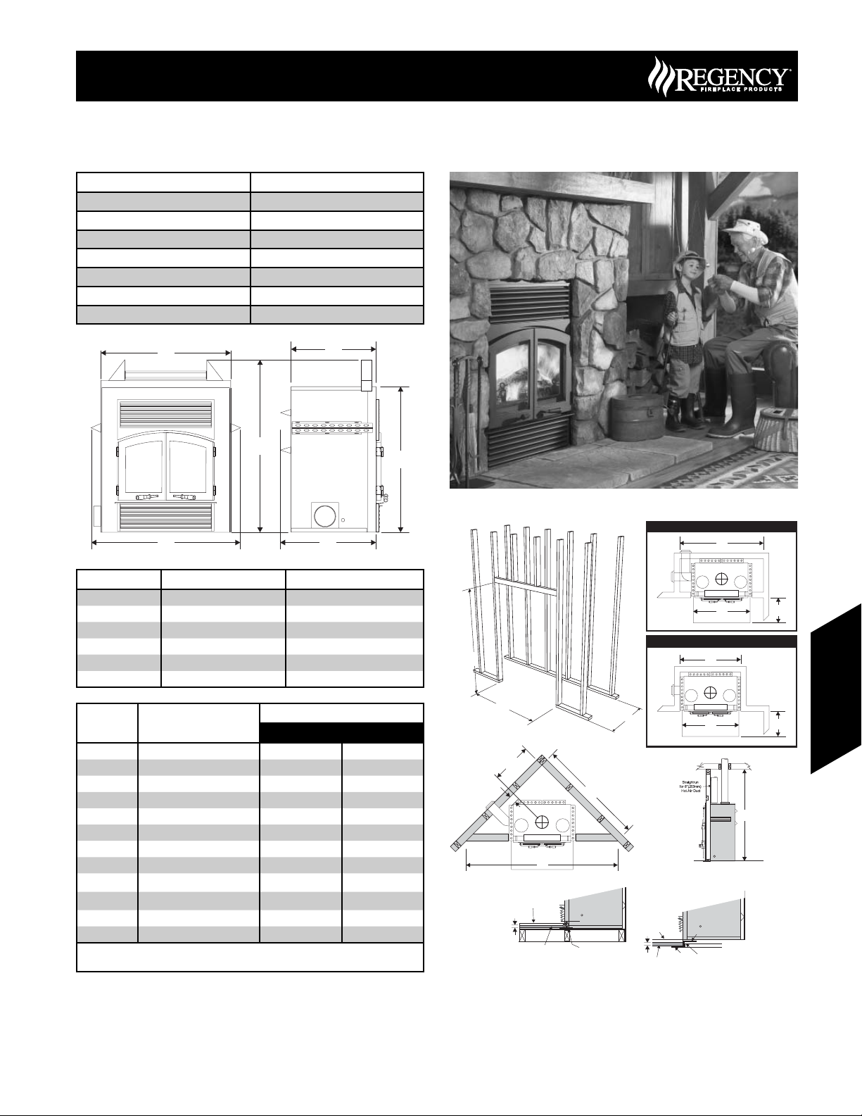
R90 Wood Fireplace
Model R90
Emissions 3.72 g/hr
Effi ciency (EPA) 63%
BTU/h (EPA) 11,720 (Low) to 42,400 (High)
Flue Size 8” (203mm) Diameter
Log Size 20” (508mm)
Shipping Weight 612 lbs. (278 kg)
Stripped Weight 570 lbs (259 kg)
R90 Wood Fireplace
C
F
B
D
A E
Unit Dimensions Description R90
A Unit Width w/ standoffs 43-5/8” (1108mm)
B Unit Height w/ standoffs 50-1/2” (1283mm)
C Unit Width 38” (965mm)
D Unit Height 42-5/8” (1067mm)
E Unit Depth w/ standoffs 28” (711mm)
F Unit Depth 25” (635mm)
Framing
Dimensions
G Framing Width 44” (1118mm) 44” (1118mm)
H Framing Height 50-3/4” (1289mm) 50-3/4” (1289mm)
I Framing Depth 28” (710mm) 28” (710mm)
J Corner Wall Length 68” (1729mm) 81-1/2” (2072mm)
K Corner Facing Wall Width 96-1/4” (2445mm) 115-3/8” (2930mm)
L Inside Corner to Center Vent 24-1/2” (624mm) 31-1/4” (795mm)
M Unit Corner Clearance 3” (76mm) 9-3/4” (248mm)
N Inside Chase Framing Width 44” (1118mm) 60” (1524mm)
O
P
Q Thermal Protection Thickness 1/2” (12.7mm) 1/2” (12.7mm)
R Combustible Ceiling Height 84” (2134mm) 84” (2134mm)
Description
Hearth
** Depth
** Width
Hearth
USA Only Canada Only
18” (457mm) 18” (457mm)
40” (1016mm) 40” (1016mm)
** Required Non-combustible Hearth with thermal protection - Minimum
“K” Factor of 20.07 (CAN) or 0.84 (US)
R90
CANADA ONLY
N
P
USA ONLY
H
N
O
Wood Fireplaces
G
M
L
Finishing Material
Q
Thermal Protection
I
J
K
Finishing
Material
Safety Strip
Q
Thermal
Protection
2-1/2”
(64mm)
P
2-1/2” (64mm)
Z Type
Safety Strip
O
R
NOTE: Hearth requires thermal protection in front of the fi replace and
must have at least 1/2" (13mm) Millboard under the fi nishing
material with minimum "k" factor of 20.07 (in Canada), 0.84 (in
US). If the bottom of the unit is raised 4" (102mm) above the
hearth, the thermal fl oor protection is not required.
NOTE: Safety strip is required when the fi replace rests on a combustible
surface, and should extend 2” in front and on the sides of the
fi replace. When using a wooden support to raise the fi replace.
A “Z” type safety strip, not supplied, must be fabricated (Use 20
gauge galvanized sheet steel).
171June 2007 Regency Product Specifi cations Book
Page 2
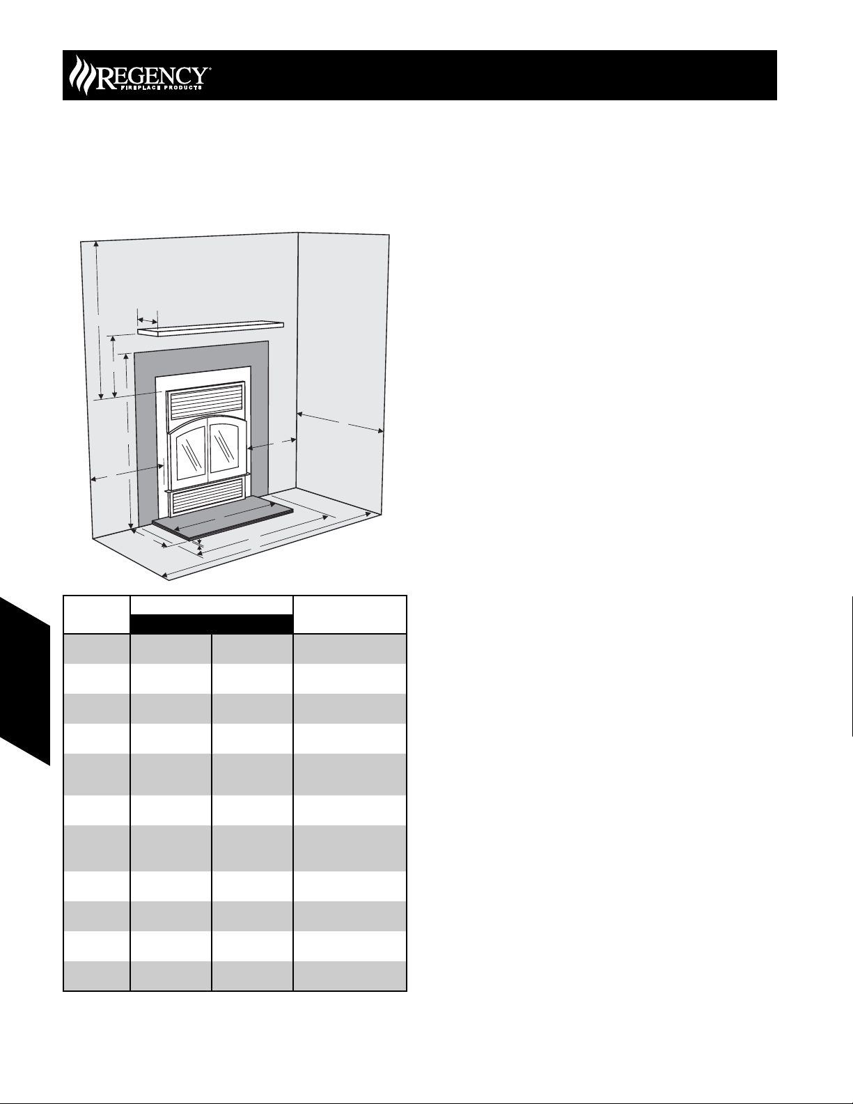
R90 Wood FireplaceR90 Wood Fireplace
Clearances Requirements
No combustible materials on the face of unit.
Required Hearth must be non-combustible and will require
thermal protection. Minimum thermal protection must have
a "k" factor of 20.07 (in Canada), 0.84 (in US).
D
A
J
B
H
I
G
Dimension
USA Only Canada Only
18” (457mm) 18” (457mm) Minimum (See Page 86)
10” (254mm) 10” (254mm) Maximum
N/A N/A
N/A N/A
1/2” (13mm) 1/2” (13mm)
40” (1016mm) 40” (1016mm) Edge to Edge of Hearth
18 ” (457mm) 18 ” (457mm) Front of Hearth to Wall
52-1/2”
(1334mm)
44” (1118mm) 60” (1524mm)
(1308mm)
K
E
51-1/2”
B
Measured From:
Side of fi replace
Top of fi replace
Approved for Single
Sidewall only
Approved for Single
Sidewall only
Bottom to top of
Floor to Facing
Edge to Edge of
Wood Fireplaces
C
Clearance:
A: Mantel
Height
B: Sidewall 18” (457mm) 24” (610mm)
C: Ceiling 46” (1168mm) 46” (1168mm)
D: Mantel
Depth
E: Alcove
Width
F: Alcove
Depth
G: Thermal
Protection
Height
H: Hearth
Width
I: Hearth
Depth
J: Facing
Height**
K: Facing
Width**
F
opening
opening
(See Page 86)
Protection.
Height**
Facing**
Wood Fireplaces
Combustibles may not extend to unit face.
Do not notch wallboard around standoffs.
The R90 may be placed on or near construction materials. The
combustion air kit, fi re stop spacer and roof fl ashings (not chase
fl ashings) may be placed directly on or against normal construction
materials. The chimney requires a minimum 2" (51mm) clearance. A
combustible mantle (to a depth of 10", 254mm) may be installed no
closer than 18" (457mm) above the warm air vent or 55-1/2" (1410mm)
from bottom of unit.
The chimney must be enclosed when installed in or passing through a
living area where combustible material or people may come in contact
with it. This is important to prevent possible personal injury or fi re
hazard.
For any further information, please call your dealer. Special restrictions
apply to the front and facing of the fi replace and nearby walls.
WARNING: If insulation is used, do not place the unit against it. Insulation
or vapor barriers, if used, must be secured to assure insulation and vapor
barriers remain in place and do not affect the required air spaces.
WARNING: Do not pack or fi ll required air spaces with insulation or other
material. No material of any kind is allowed in these areas.
NOTES:
1) Do not insulate the chase cavity with blown or fi ll type insulation
materials.
2) Local codes may not require a fi restop at the ceiling level for outside
chase installations; however, it is recommended for safety and the
reduction of heat loss.
3) We recommend that you insulate at least the fi rst fl oor of the chase
to prevent heat loss.
4) Some local codes require 1 hour fi re rating on one or all sides of
fi re chases. Check with your local authorities.
NOTES:
1) Minimum Chase sizes must be met according to the framing
directions (page 149). US Installations will require a minimum
ventilation with one 30 sq. in. (194 sq. cm.) opening grill (air is
drawn from within the home not outside).
2) Mantel min. Height of 18” (457mm) from top of louver opening to
underneath mantel or 55 1/2” (1410mm) from bottom of unit.
3) Minimum non-combustible facing must be installed according to
the table on this page. Finishing material to be installed on top of
this.
4) Framing is slightly larger than unit dimensions to allow for easier
installation (50 3/4”, 1289mm h x 44”, 1118mm w)
5) Must maintain a min. of 46” (1168mm) from top of louver opening
to fi nished ceiling.
6) Sidewall clearances, as detailed on this page, must be maintained
according to your location.
7) Hearth must be a min. 40” (1016mm) wide x 18” (457mm) deep
and 1/2” (127mm) thick.
**Required non-combustible facing.
172 June 2007 Regency Product Specifi cations Book
Page 3

Wood Fireplaces
Gravity Air Feed Kit Option
The Gravity Air Feed Kit is designed to extend the heat output vent above
the R90 to the front or the side. The upper louver opening is blocked off
and fl ex vent is connected to the vent holes in the top of the unit and
run to discharge vent grilles. Both 8" (203mm) diameter insulated Flex
vents must be used along with one 30 sq. inch (194cm
to bring additional air into the chase (for U.S. installations only).
Qty Description
4 Connector Collars
4 Adjustable Clamps
2 5’ lengths of fl exible vent pipe (8” dia.)
2 Insulated Sleeves
1 Block Off Plate
2 Discharge Vent Mounting Frames
7 1/4-20 x 1/2” Truss Head Screws (used for EX90/R90 only)
2 16 x 8 Discharge Vent Grilles
4 #8 Drywall Anchors
4 Insulation Strips
1 Chase Vent Frame (for U.S. installations only)
1 8 x 8 Chase Vent Grille (for U.S. installations only)
Ceiling
Flue
Clamp
Flex Vent
Alternate Position for
Chase Vent Grill
Insulation
Strips
Discharge Vent
Grill
Connector
Collar
Chase Vent
Grill
Outside Air
Intake
30 sq.in. (194 sq.cm)
opening
Connector
Collar
1) Remove the screw from the vent hole cover (vent cover 'A') on top
of the unit.
2) Take the connector collar and press and rotate it into the hole to
cut through the insulation layer. Remove the collar and remove
insulation from the collar. The screws for the inner cover should
be exposed.
3) Remove the screws from the inner cover (vent cover 'B') and slide
it back under the insulation.
4) Extend fl ex vent and pull the insulation sleeves over the 8” (203mm)
diameter fl ex vents. Leave a short section of fl ex vent exposed at
each end. On one end insert the collar into the fl ex vent and use
a clamp to hold the fl ex vent in place.
5) Use tin snips to cut slits into the rim of the connector collar. A
minimum of four tabs will be required so cut the slits 1” (25mm) (i.e.
1” (25mm) wide tabs) apart around the perimeter of the collar.
6) Install the connecting collar into the top of the unit until the bead of
the collar rests against the top of the inner top of the unit. Reach
inside the upper louver opening and use pliers to bend the tabs
(minimum 4) out on the connector collar. A hammer may be
required to lightly tap the tabs and bend them so that they fi t tightly
against the bottom of the inner top. Pull the insulation sleeve down
to the top of the unit. Repeat steps 1-6 for the second fl ex vent and
collar assembly.
2
) chase vent grill
6" (152mm) Min.
To Rouch Opening
Center-line
of Vent
Vent Cover 'A"
Vent Cover 'B'
(Inside)
Base of Stove
Block-off Plate
(replace top louver)
R90 Wood FireplaceR90 Wood Fireplace
Flex Vent
7) Position the vent frames for the Discharge Grilles into the rough
opening of the stud wall framing. Make sure to add two insulation
strips behind the fl anges of the frame prior to securing to wall. The
frames will fi t between studs framed at 16” (406mm) on center. Use
4 nails or screws to mount the frame to the stud framing.
Insulation
Strips
Discharge
Vent Grille
Connecting
Collar
Discharge Vent
Frame
Clamp
Flex
Vent
8) Insert the connecting collar into the other end of the 5 ft. (1.5m)
fl ex vent and use an adjustable clamp to hold the vent in place.
Cut tabs into the rim of the connector collar (a minimum of 4 tabs
will be required). Push the collar through the 8” (203mm) hole in
the mounting frame. Use pliers to bend out tabs (minimum 4) to
secure the collar to the mounting frame.
9) Pull the insulation sleeve up the fl ex vent to the back of the mounting
frame. The fl ex vent should now be connected to both the unit and
the mounting frames securely. Repeat steps 1-8 for the second fl ex
vent assembly.
10) Install the block-off plate to the unit. The block-off plate will cover
the upper louver opening of the unit and force the fan air to
circulate through the two 8” (203mm) diameter fl ex vents. Put high
temperature sealant onto the block-off plate. Mount the block-off
plate onto the front of the unit and cover the upper louver opening.
Make sure that all exposed holes in the block-off plate are sealed
with high temperature sealant
NOTE: Make sure the block-off plate is fl ush and
fastened tightly to the Regency R90 Fireplace.
11) The rough opening size for the Chase Vent Grille is 3” H x 10” W
(76mm H x 254mm W).
WARNING: A chase vent of 30 sq. inches (194 cm2)
MUST be installed in all applications, otherwise serious
overheating of the chase may result. Use the chase
vent supplied with the R90 unit only or any equivalent
one with the same or less restriction of air fl ow.
12) Recheck all fl ex vent-work connections to make sure that they are
secure. Install wall sheathing and cut-out openings for the chase
ventilation, and hot air discharge outlets.
13) Install the Chase Vent Grille and install the Discharge Vent Grilles
for the hot air outlets.
NOTE: There must be a minimum of 5" (127mm)
between the gravity air vents.
Wood Fireplaces
173June 2007 Regency Product Specifi cations Book
 Loading...