

Page 1
Owners &
Installation
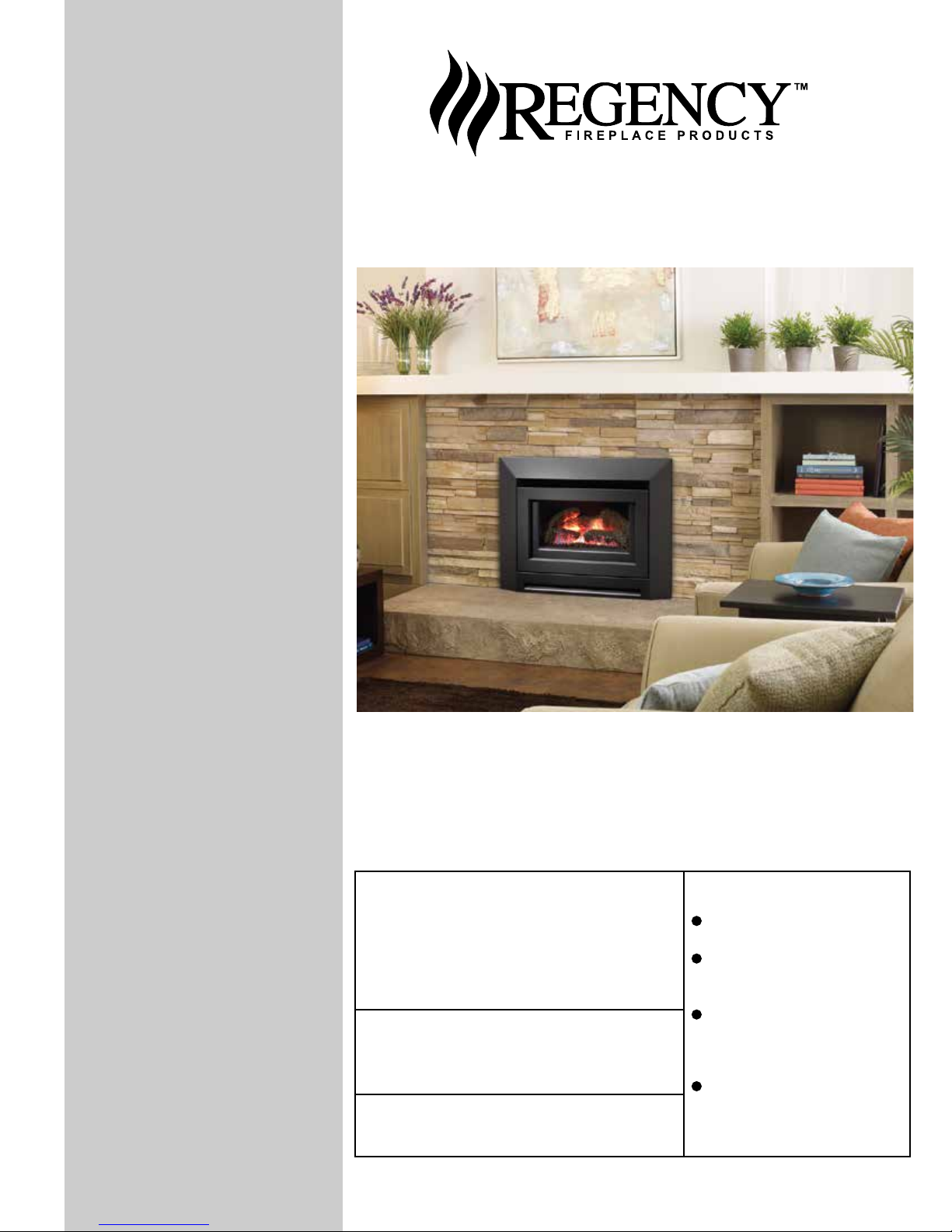
IP28 GAS INBUILT
Manual
LISTINGS AND CODE APPROVALS
These gas appliances have been tested in
accordance with AS4553, NZS 5262 and
have been certied by the Australian Gas
Association for installation and operation as
described in these Installation and Operating
Instructions.
Your unit should be serviced annually by
an authorised service person.
Models: IP28-NG
IP28-PROPANE
IP28-ULPG
PLEASE KEEP THESE INSTRUCTIONS FOR FUTURE
REFERENCE
WARNING:
Improper installation, adjustment, alteration, service or maintenance can cause
injury or property damage. Refer to this
manual. For assistance or additional information consult an authorised installer,
service agency or the gas supplier.
FOR YOUR SAFETY
Do not store or use gasoline or other ammable vapours and liquids in the vicinity of
this or any other appliance.
Installation and service must be performed
by an authorised installer, service agency or
the gas supplier.
FOR YOUR SAFETY
What to do if you smell gas:
Do not try to light any appli-
ance
Do not touch any electri-
cal switch: do not use any
phone in your building.
Immediately call your gas
supplier from a neighbour's
phone. Follow the gas supplier's instructions.
If you cannot reach your
gas supplier, call the re
department.
918-938f
04/07/15
Page 2
REGENCY
GAS INBUILT FIREPLACE
TO THE NEW OWNER
Congratulations! You are the owner of a state-of-the-art Gas Inbuilt Fireplace by FPI. The Regency
Gas Fireplace Series of appliances has been designed to provide you with all the warmth and
charm of a replace, at the ick of a switch. The model IP28 of this series has been approved
by Australian Gas Association for both safety and efciency. As it also bears our own mark, it
promises to provide you with economy, comfort and security for many trouble free years to follow.
Please take a moment now to acquaint yourself with these instructions and the many features of
your Regency Fireplace.
2
Regency IP28 Gas Inbuilt Fireplace
Page 3
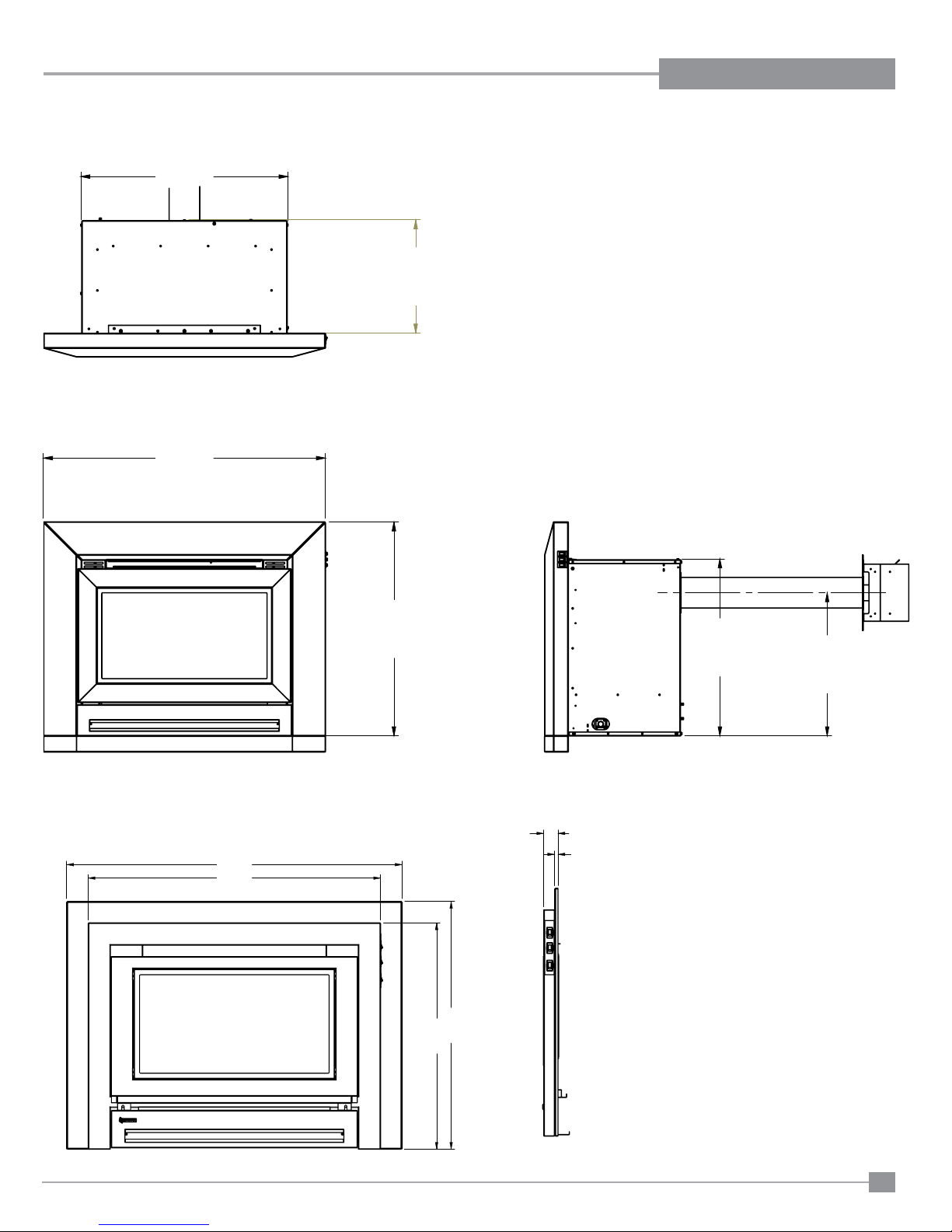
UNIT DIMENSIONS W/ CONTEMPORARY FACEPLATE
27.298
(694mm)
14.911
(379mm)
37.150
(944mm)
DIMENSIONS
38-5/16"
(973mm)
33-1/2"
(848mm)
28.180
(716mm)
MODULAR FACEPLATE AND INFILL PANEL
1-5/8"
25-7/8"
(657mm)
28-5/16"
(719mm)
(41mm)
3/8"
(10mm)
23.327
(593mm)
18.850
(476mm)
Regency IP28 Gas Inbuilt Fireplace
3
Page 4
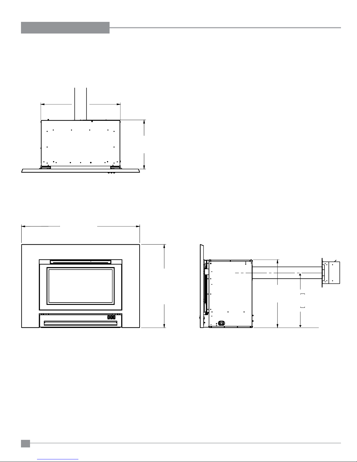
DIMENSIONS
27-5/16”
(693mm)
UNIT DIMENSIONS W/ SLIM LINE FACEPLATE
(427mm)
16 - 7/8”
40-1/2”(1030mm)
28-5/8” (725mm)
23-3/8”
(593mm)
475.8
18.850
4
Regency IP28 Gas Inbuilt Fireplace
Page 5
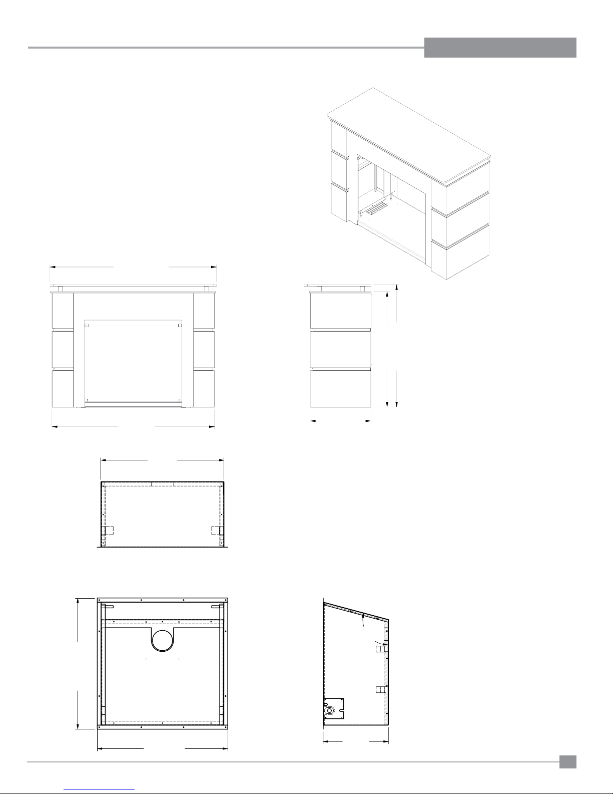
DIMENSIONS
49”(1245mm)
775mm
DIMENSIONS - OPTIONAL MODULAR FIREPLACE SOLUTION
50-3/16” (1275mm)
34-7/8”(886mm)
36-15/16”(938mm)
18-5/16”(465mm)
DIMENSIONS - OPTIONAL WEATHER BOX
1
0
5
°
822mm
819mm
Regency IP28 Gas Inbuilt Fireplace
410mm
5
Page 6

TABLE OF CONTENTS
DATA BADGE
Copy of Data Badge .....................................................4
INSTALLATION
Important Message ........................................................8
For Your Safety ..............................................................8
Materials Required ........................................................8
Before You Start ............................................................8
Masonary Minimum Fireplace Opening Dimensions .....9
Contemporary Fascia ....................................................9
Slim Line Fascia ............................................................9
Combustible Mock replace" Minimum Fireplace opening
Dimensions ....................................................................9
Clearances To Combustibles .........................................9
Optional Modular replace solution Clearances ..........10
Mock Fireplace kit (zero clearance) installation........... 11
Gas Pipe Pressure Testing ..........................................12
Exterior Flue Termination Locations ............................ 13
Venting and termination ...............................................14
Aeration Settings .........................................................15
Conversion Kit for NG to LPG Model...........................16
Conversion Kit for NG to ULPG Model ........................17
Optional Stainless steel inner panel install ..................21
Switch operation ..........................................................22
Log set installation .......................................................23
Glass Door installation.................................................24
Contemporary faceplate Installation ............................25
Hearth trim Installation.................................................26
Slim line faceplate Installation .....................................27
Optional inll panel Installation ....................................28
Modular faceplate Installation ......................................29
Final Check..................................................................30
Wiring ..........................................................................30
Standard wiring............................................................30
OPERATING INSTRUCTIONS
Operating Instructions ................................................31
Lighting Instructions.....................................................31
Shutdown Instructions .................................................31
First Fire ......................................................................31
Remote Control ..........................................................31
Copy Of Lighting Instruction Plate ...............................33
Normal Operating Sounds Of .....................................33
Gas Appliances............................................................33
Resetting the unit.........................................................33
MAINTENANCE
Door Glass ..................................................................35
Replacement ...............................................................35
Glass Gasket ...............................................................35
Convection Fan replacement.......................................36
Combustion Fan replacement .....................................37
Pressure switch replacement ......................................38
Valve assembly replacement .......................................39
PARTS LIST
Main Assembly ............................................................41
Contemporary Faceplate Assembly.............................42
Slim line Faceplate Assembly ......................................42
WARRANTY
Warranty ......................................................................43
6
Regency IP28 Gas Inbuilt Fireplace
Page 7
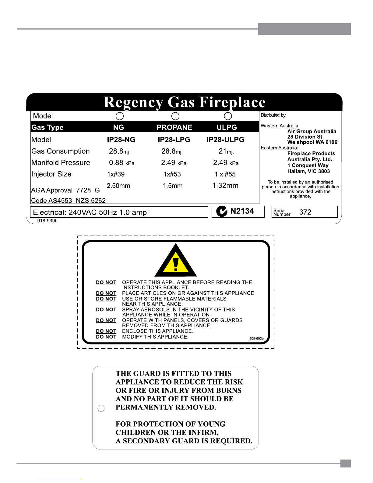
SAFETY LABEL
This is a copy of the label that accompanies each Regency IP28 Gas Inbuilt replace. We have printed a copy of the contents here for your review.
DATA BADGE NOTE: Regency units are constantly being improved. Check the label on the unit and if there is a difference, the label on the unit is the
correct one.
Regency IP28 Gas Inbuilt Fireplace
(Australia Only)
7
Page 8

INSTALLATION
IMPORTANT MESSAGE
The Regency Gas Inbuilt must be installed in accordance with these instructions. Carefully read all
the instructions in this manual rst.
Note: Failure to follow these instructions could
cause a malfunction of the heater which
could result in death, serious bodily injury, and/or property damage. Failure to
follow these instructions may also void
your re insurance and/or warranty.
FOR YOUR SAFETY
This appliance requires air for proper combustion.
Always provide adequate combustion and ventilation air. Follow instructions and information in the
current AS5601, NZS 5262 or local codes. Consult
the "authority having jurisdiction" to determine the
need for a permit prior to starting the installation.
MATERIALS REQUIRED
BEFORE YOU START
INSTALLATION AND REPAIR SHOULD
BE DONE ONLY BY AN AUTHORISED
PERSON.
1) The appliance shall be installed in accordance
with the manufacturer's installation instructions,
local gas tting regulations, municipal building
codes, water supply regulations, electrical wiring regulations, with AS5601. (AGA gas installation code) NZS 5262(New Zealand). Special
conditions ie. marine environment, should be
avoided.
2) The appliance should be inspected before
use and at least annually by an authorised
service person. More frequent cleaning may
be required due to excessive lint from carpeting, bedding material, etc. It is imperative that
control compartments, burners and circulating
air passageways of the appliance be kept clean
and free from excessive lint from carpeting.
3) Always connect this space heater to a approved
ueing and termination provided. Flue to the
outside of the building envelope. Never ue to
another room.
4) Inspect the ueing system annually for blockage
and any signs of deterioration.
A 240 Volt AC power cord is hooked up to the unit.
Plug 3 wire cord into a suitable receptacle. Do not
cut the ground terminal off under any circumstances.
When connected with 240 volts, the appliance
must be electrically grounded in accordance with
local codes.
This unit is polarity sensitive and will not
operate if polarity is incorrect.
The power connection must be accessible with
the appliance installed as per AS5601.
5) Any safety glass removed for servicing must
be replaced prior to operating the appliance.
6) To prevent injury, do not allow anyone who is
unfamiliar with the operation to use the replace.
GAS CONNECTION WARNING
Only persons licensed to work with gas piping
may make the necessary gas connections to
this appliance.
8
Regency IP28 Gas Inbuilt Fireplace
Page 9
INSTALLATION
2
0
12
64810
27-1/2” (699mm)
490mm
770mm
450mm
27-1/2”
(699mm)
17” (432mm)
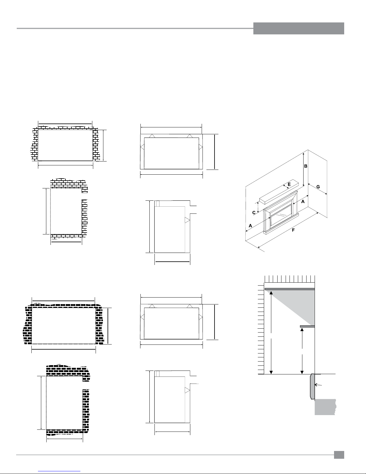
MASONARY MINIMUM
FIREPLACE OPENING
DIMENSIONS
(CONTEMPORARY FASCIA)
The minimum replace dimensions for the
Regency gas space heater when using the
Contemporary Fascia are shown in the following diagrams:
NOTE: ALLOW FOR SIDE GAS CONNECTION - IF REQUIRED
15-1/8” (384mm)
27-1/2” (699mm)
COMBUSTIBLE
"MOCK FIREPLACE"
MINIMUM FIREPLACE
OPENING DIMENSIONS
The minimum replace dimensions for the
Regency gas space heater when installing into
a combustible mock replace are shown in the
following diagrams:
(For Contemporary Fascia)
770mm
770mm
CLEARANCES TO
COMBUSTIBLES
Minimum Clearances to Combustibles
From Unit
Sides A 2" / 51mm
Ceiling B 39-3/8" / 1000mm
Mantel C 11" / 279mm
Max. Mantle Depth E 12" / 305mm
(see Dia. 2)
Min. Alcove Width F 44-7/8" / 1139 mm
Max. Alcove Depth G 36" / 914 mm
*No hearth required.
23-1/2” (597mm)
15-1/8” (384mm)
(SLIM LINE FASCIA)
The minimum replace dimensions for the Regency
gas space heater when using the Slim line Fascia
are shown in the following diagrams:
NOTE: ALLOW FOR SIDE GAS CONNECTION
- IF REQUIRED
28-7/8”
(735mm)
17” (432mm)
702mm
490mm
(For Slim line Fascia)
770mm
Mantel Clearances
20
18
16
14
12
10
8
6
4
2
0
12"Mantel
(305mm)
20”(508mm)
11"(279mm)
3-1/2" (89mm)
Mantel
Top
Faceplate
23-1/2” (597mm)
Regency IP28 Gas Inbuilt Fireplace
702mm
490mm
9
Page 10
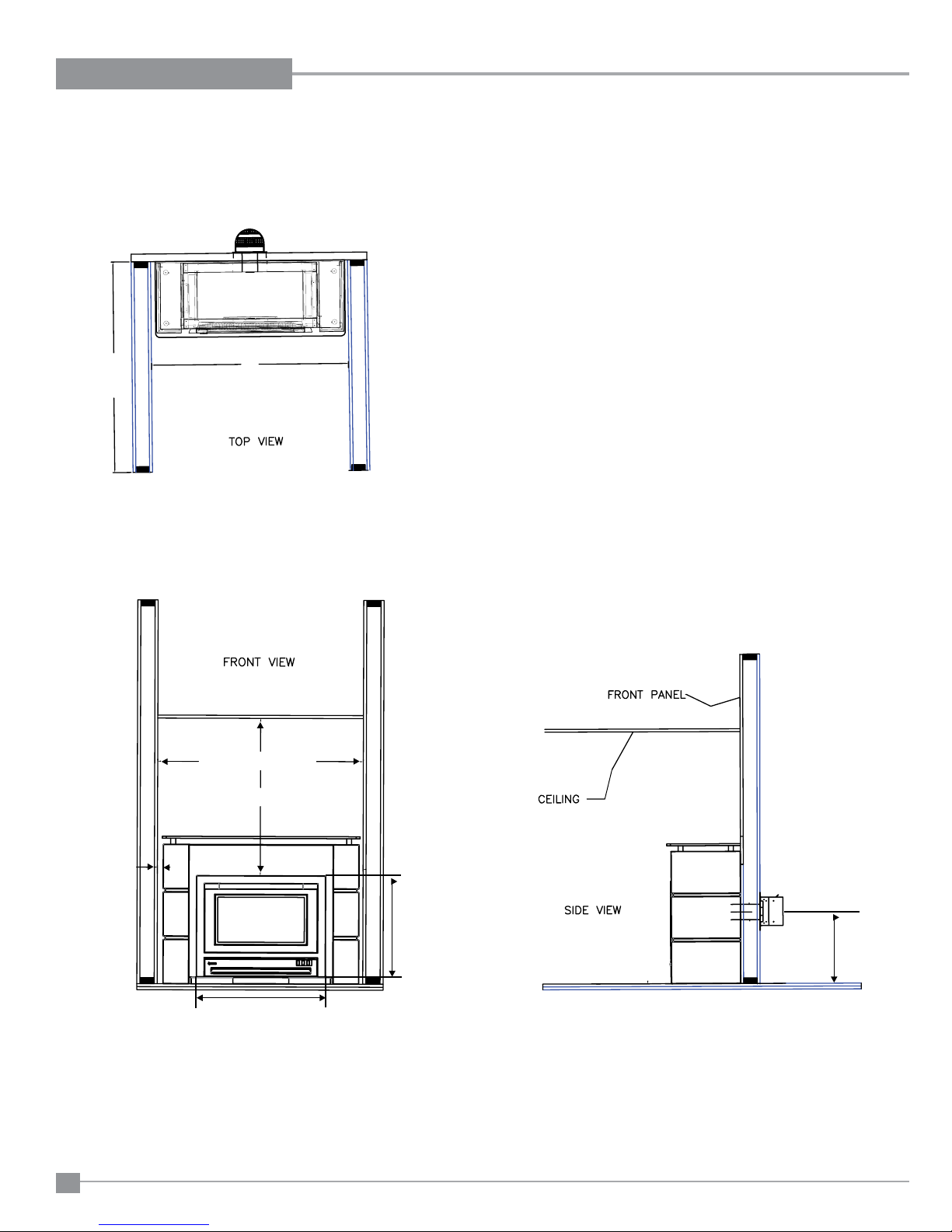
INSTALLATION
51-7/16” (1305mm)
39-3/8” (1000mm)
1-7/16”
(37mm)
36”
(914mm)
51-7/16” (1305mm)
33-7/16” (848mm)
25-7/8”
(655mm)
20-5/8”
(523mm)
IP28
490mm
702mm
450mm
770mm
770mm
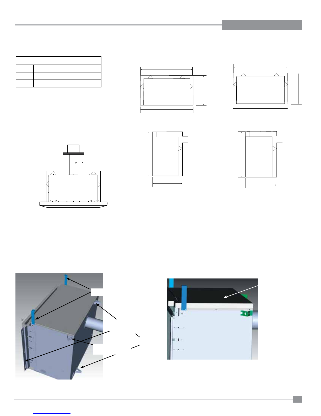
MOCK FIREPLACE KIT (ZERO CLEARANCE) INSTALLATION
Zero Clearance Kit
6 Standoffs
2 Side Brackets
1 Insulation Blanket
COMBUSTIBLE MOCK FIREPLACE KIT INSTALLATION:
Minimum cavity size for Low profi le faceplate:
702mm Height x 770mm Width x 490mm Depth
Minimum cavity size for Contemporary faceplate:
702mm Height x 770mm Width x 450mm Depth
VENTING CLEARANCES: 10mm is required all around
venting
INSTALLATION OF MOCK FIREPLACE KIT:
1) Install top two 110 mm stand offs to the top of unit.
Install two 67 mm stand offs to the back of unit - install two 55 mm stand offs to the each side of unit.
2) Install left and right side nailing fl ange.
3) Lay insulation blanket on top of unit so it is fl ush and tight against backside of faceplate.
4) Unit is now ready for install into a combustible cavity that has the above mentioned clearances.
10mm
Top standoffs x 2
Back standoffs x 2
Insulation blanket
Side standoffs x 2
1 on each side
Side Nailing Flange x 2
1 on each left & right
490mm
702mm
490mm
770mm
770mm
NOTE: Please adjust nailing fl anges in relationship to either Contemporary or Low Profi le Faceplate. Faceplate needs to be fl ush against fi nished wall.
Low Profi le Fascia
Contemporary Fascia
OPTIONAL MODULAR FIREPLACE SOLUTION CLEARANCES
10
Regency IP28 Gas Inbuilt Fireplace
Page 11
INSTALLATION
IP28
MOCK FIREPLACE KIT (ZERO CLEARANCE) INSTALLATION
MOCK FIREPLACE KIT (ZERO CLEARANCE) INSTALLATION
Zero Clearance Kit
6 Standoffs
2 Side Brackets
1 Insulation Blanket
COMBUSTIBLE MOCK FIREPLACE KIT INSTALLATION:
Minimum cavity size for Low profi le faceplate:
702mm Height x 770mm Width x 490mm Depth
Minimum cavity size for Contemporary faceplate:
702mm Height x 770mm Width x 450mm Depth
VENTING CLEARANCES: 10mm is required all around
venting
10mm
Low Profi le Fascia
770mm
770mm
702mm
490mm
490mm
Contemporary Fascia
770mm
450mm
770mm
702mm
490mm
INSTALLATION OF MOCK FIREPLACE KIT:
1) Install top two 110 mm stand offs to the top of unit.
Install two 67 mm stand offs to the back of unit - install two 55 mm stand offs to the each side of unit.
2) Install left and right side nailing fl ange.
3) Lay insulation blanket on top of unit so it is fl ush and tight against backside of faceplate.
4) Unit is now ready for install into a combustible cavity that has the above mentioned clearances.
Top standoffs x 2
Side Nailing Flange x 2
1 on each left & right
Back standoffs x 2
Side standoffs x 2
1 on each side
Insulation blanket
NOTE: Please adjust nailing fl anges in relationship to either Contemporary or Low Profi le Faceplate. Faceplate needs to be fl ush against fi nished wall.
Regency IP28 Gas Inbuilt Fireplace
11
Page 12
INSTALLATION
GAS PIPE PRESSURE
TESTING
The appliance must be isolated from the gas supply
piping system by closing its individual manual shutoff valve during any pressure testing of the gas
supply piping system at test pressures equal to or
less than 1/2 psig. (3.45 kPa). Disconnect piping
from valve at pressures over 3.45 kPa (14" w.c.).
The manifold pressure is controlled by a regulator
built into the gas control, and should be checked
at the pressure test point.
Note: To properly check gas pressure, both
inlet and manifold pressures should
be checked using the valve pressure
ports on the valve.
1) Make sure the valve is in the "OFF" position.
2) Loosen the "IN" (# 3) and/or "OUT" (# 4)
pressure tap(s), turning counterclockwise with
a 1/8" wide at screwdriver.
3) Attach manometer to "IN" and/or "OUT"
pressure tap(s) using a 5/16" (8mm) ID hose.
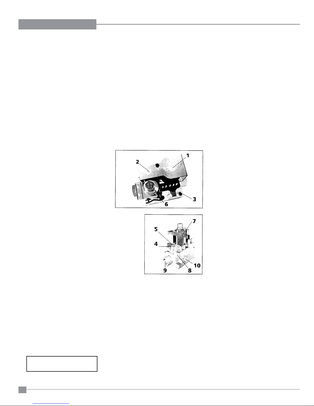
S.I.T. Valve Description
1) On-Off Solenoid Valve EV1
2) On-Off Solenoid Valve EV2
3) Inlet Pressure Test Point
4) Outlet Pressure Test Point
5) Connection for Pressure Regulator/
Combustion Chamber Compensation
6) Pressure Regulator for Minimum and
Maximum Outlet Pressure
7) Gas Outlet Pressure Electric Modulator
8) Pilot Outlet
9) Main Gas Outlet
10) Side Outlet
4) Seal and or check the pilot outlet (# 8)
5) The pressure check should be carried out
with the unit burning and the setting should be
within the limits specied on the safety label.
6) When nished reading manometer, turn off the
gas valve, disconnect the hose and tighten the
screw (clockwise) with a 1/8" at screwdriver.
Screw should be snug, but do not over tighten.
Install to AS5601 (Australia) /
NZS 5262 (New Zealand)
12
Regency IP28 Gas Inbuilt Fireplace
Page 13
INSTALLATION
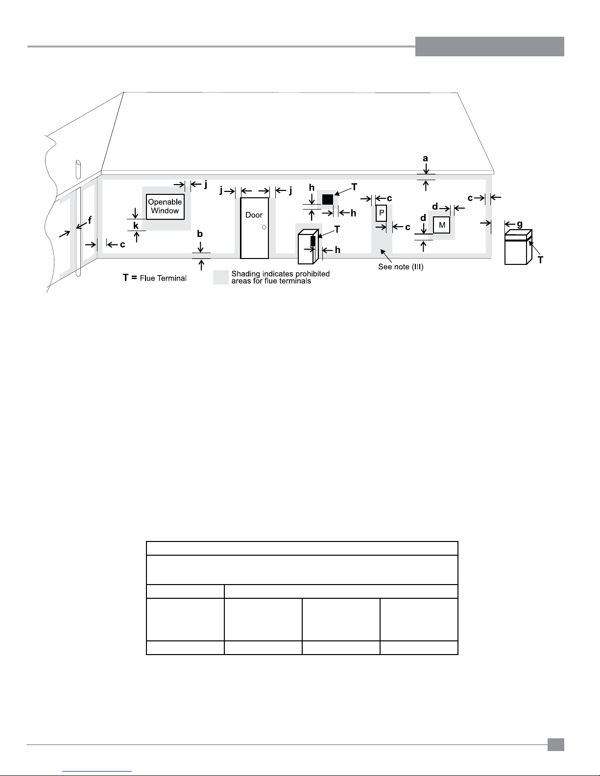
EXTERIOR FLUE TERMINATION LOCATIONS
Minimum clearances required for balanced ue terminals or
the ue terminals of outdoor appliances
according to AS5601-2004 (AGA gas installation code) or NZS 5262 (New Zealand)
and local authorities having jurisdiction.
Minimum Clearance (mm)
a Below eaves, balconies or other projections:
- Appliances up to 50 MJ/h input 300
- Appliances over 50 MJ/h input 500
b From the ground or above a balcony 300
c From a return wall or external corner 500
d From a gas meter (M) 1000
e From an electricity meter or fuse box (P) 500
f From a drain or soil pipe 150
g Horizontal from any building structure (unless appliance is approved
for closer installation) or obstruction facing a terminal 500
h From any other ue terminal, cowl or combustion air intake 500
j Horizontally from an openable window, door, or non-mechanical air inlet, or
any other opening into a building, with the exception of sub-oor ventilation
(see also Note (I)):
- Appliances up to 150 MJ/h input 500
- Appliances over 150 MJ/h input 1500
k Vertically below an openable window, door, or non-mechanical air inlet,
or any other opening into a building, with the exception of sub-oor ventilation
(see also Note (I)): see table below
Clearance 'k' in mm
Space Heaters All Other Appliances
Up to 50 MJ/h
input
Up to 50 MJ/h Over 50 MJ/h input
to 150 MJ/h input
Over 150 MJ/h
input
150 500 1000 1500
(I) For mechanical air inlets, including spa blowers, the clearance 'j' and 'k' shall be 1500 mm in all cases.
(II) All distances shall be measured vertically or horizontally along the wall to a point in line with the nearest par to of the terminal.
(III) Prohibited area below electricity meter or fuse box extends to ground level.
(IV) A ue terminal of this type shall not be located under a roofed area unless the roofed area is fully open on at least two sides and a free ow of air at the
appliance is achieved.
Regency IP28 Gas Inbuilt Fireplace
13
Page 14
INSTALLATION
VENTING AND TERMINATION
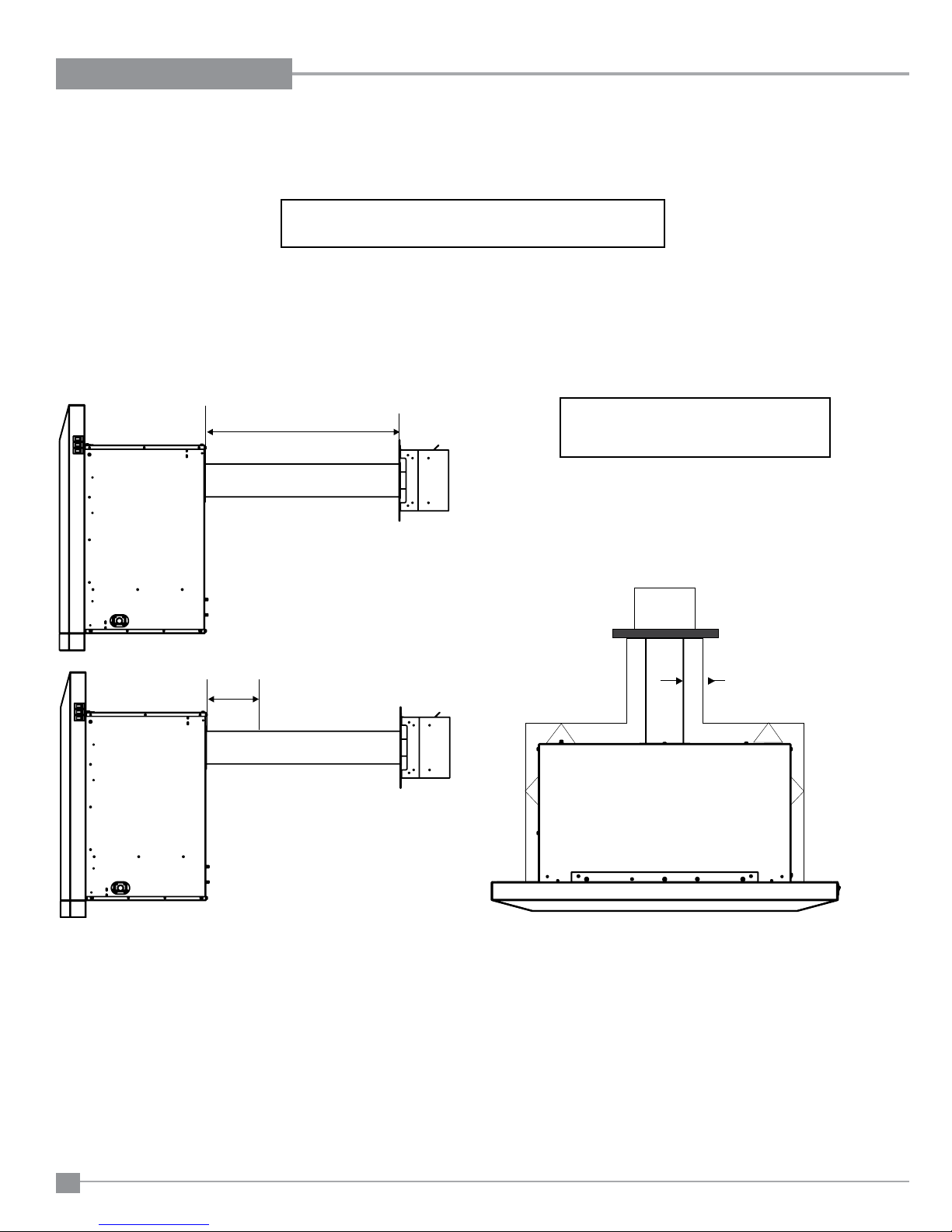
This flueing system in combination with the IP28 unit has been tested and listed as a power flue system by the Australian Gas Association.
The termination location must conform to AS5601 as per the diagram in the "Flue Termination Location" section of the manual.
Venting must have slight downward slope towards terminal.
Masonry and Mock Fireplace Installations:
IP28 must be fitted with the venting and terminal provided.
Ensure cavity is prepared and ready to accept unit and proper measurements are taken to ensure proper vent length and sealing of the terminal and venting.
Preparation of venting for Installation
Maximum and minimum vent lengths:
MAX LENGTH: 605mm
MIN LENGTH: 130mm
NOTE: All vent lengths must have 0.4 degree slope downwards.
24”
605mm
Venting cannot be run vertically.
THIS UNIT MUST ALWAYS
TERMINATE / VENT DIRECTLY TO THE
OUTDOORS.
5”
130mm
10mm
CLEARANCES TO COMBUSTIBLES: 10mm is required all around the outer pipe.
1) Install inlet tube to back of unit with screws provided and mark ‘’cut line’’. Remove inlet tube from unit and cut tube to proper length to ensure
sealing at the terminal end.
2) Do the same as above for the outer tube. Secure to unit, ‘’mark cut line’’, remove from unit, and cut tube to proper length to ensure sealing at the
terminal end.
3) Re-install both the inner exhaust tube and outer fresh air tube to the unit.
Be sure not to damage the gasketing. Ensure both the inner and the outer are flush on the ‘’terminal side’’ and measurements are correct.
Once the venting is properly secured to the unit at the correct measurements for the cavity, the unit is now ready for installation.
14
Regency IP28 Gas Inbuilt Fireplace
Page 15
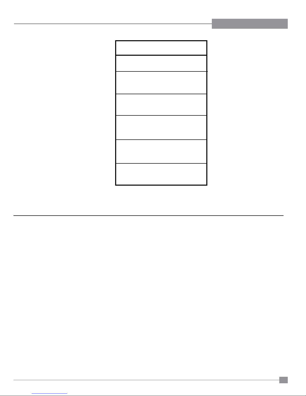
System Data
IP28
Burner Inlet Orice Sizes:
NG Propane ULPG
Burner #39 #53 #55
Max. Input
NG 28.8 mj
Propane 28.8 mj
ULPG 21 mj
Supply Pressure
NG 1.13 kPa
Propane 2.75 kPa
ULPG 2.75 kPa
Manifold Pressure HIGH LOW
NG 0.88 kPa 0.4kPa
Propane 2.49 kPa 1.6kPa
ULPG 2.49 kPa 1.6kPa
Electrical: 240 V. 50Hz.
Circulation: High/LO speed fan,
Log Set: Ceramic bre, 4 per set.
Aeration Setting
NG 7.94mm open
Propane 15mm open
ULPG 15mm open
INSTALLATION
AERATION SETTINGS
The burner aeration is factory set but may need adjusting due to either the local gas supply, air supply or altitude. This adjustment is performed by the installer.
(Close the aeration for a more yellow ame, or open it to make the ame bluer). Please adjust and lock into place via screw.
NG: 7.94mm open
LPG 15mm open
ULPG 15mm open
Note: Any damage due to carboning resulting from improperly setting the aeration is NOT covered under warranty.
Regency IP28 Gas Inbuilt Fireplace
15
Page 16
INSTALLATION
Conversion Kit for NG to LPG Model
THIS CONVERSION MUST BE DONE BY A QUALIFIED GAS FITTER IF IN DOUBT DO NOT DO THIS CONVERSION !!
Conversion Kit 456-967 Contains:
Qty. Part # Description
1 904-345 Burner Orice #53
1 908-528 Red "LPG" label
1 918-272 Label "Converted to ULPG"
1 919-107 Instruction Sheet
1) Shut off the gas supply and unplug the power
cord.
2) Remove the primary guard and faceplate.
Unplug polarized plug for the switches.
3) Remove the front door.
4) Remove logs.
5) Remove the grate.
6) Remove the burner and adjust the aeration
setting to 15 mm fully open.
7) Remove burner orice with a 1/2" wrench and
discard. Use a wrench to hold on to the elbow
behind the orice.
8) Reinstall new burner orice LPG stamped #53
and tighten.
9) Stick the conversion label "This unit has been
converted to LPG" over top of the serial number
decal.
Minimum pressure: Turn unit "ON" to it's
lowest input rating by setting the burner
switch to "LOW". While holding the nut (B)
with a wrench, screw in the screw (C) to
increase the pressure and screw it out to
decrease it. Use a screwdriver 6 x 1 blade.
NOTE: The outlet pressure must be set to
minimum 1.60 kPa.
After carrying out all adjustments, block the
setting screws with paint, taking care not to
obstruct the breather orice of the pressure.
Put back the modulator plastic cap.
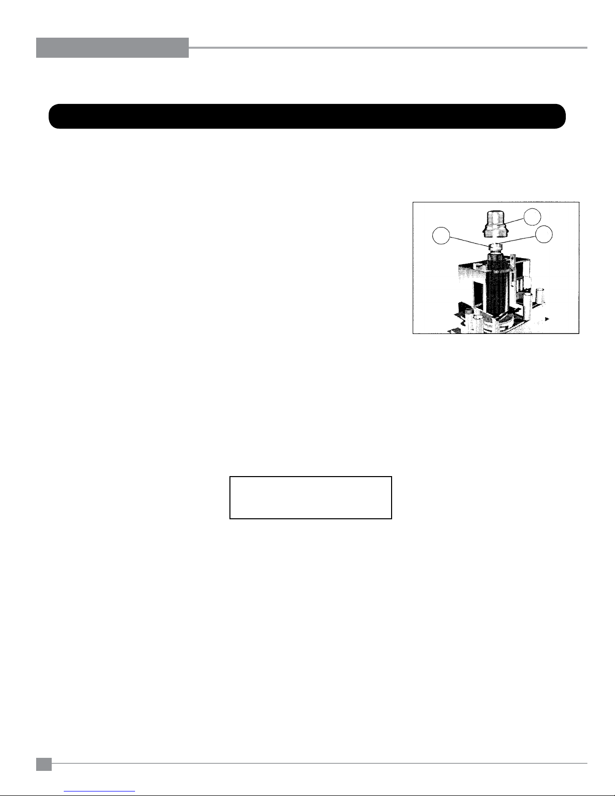
WARNING: To ensure the correct opera-
tion of the modulator it is necessary that
the plastic cap (A) is returned to its original
location.
13) Turn on gas supply and plug in power cord.
14) At the end of all setting and adjustment
operations, check electrical installation and
gas leaks.
15) Check operation of ame control.
16) Check for proper ame appearance and
glow on logs.
B
A
C
Figure 1
10) Replace the yellow "NG" label with the red
"LPG" label.
11) Reverse steps 6-2.
12) Adjusting the Outlet Pressure
All the adjustments must be carried out
in the following order:
Remove the modulator plastic cap (A) using
needle nose pliers.
Maximum pressure: Turn unit "ON" to it's
highest input rating by setting the burner switch
to "HIGH" Screw in the nut (B) to increase the
outlet pressure and screw it out to decrease
it. Use a 10 mm wrench.
NOTE: The outlet pressure must be set to
maximum 2.49 kPa.
WARNING: When adjusting maximum pres-
sure do not screw the nut in fully.
If unable to obtain 2.49kPa outlet,
check inlet pressure is adequate.
Damage may occur to the gas valve
if maximum pressure adjustment is
fully screwed in.
Installer Notice:
These instructions must be left
with the appliance.
16
Regency IP28 Gas Inbuilt Fireplace
Page 17
INSTALLATION
IP28
Conversion Kit for NG to ULPG Model
THIS CONVERSION MUST BE DONE BY A QUALIFIED GAS FITTER IF IN DOUBT DO NOT DO THIS CONVERSION !!
Conversion Kit for NG to ULPG Model
THIS CONVERSION MUST BE DONE BY A QUALIFIED GAS FITTER IF IN DOUBT DO NOT DO THIS CONVERSION !!
Conversion Kit # 456-967 Contains:
Qty. Part # Description
1 904-575 Burner Orifi ce #55
1 908-273 Red "ULPG" label
1 918-272 Label "Converted to ULPG"
1 919-121 ULPG data badge overlay
1 919-107 Instruction Sheet
1) Shut off the gas supply and unplug the power
cord.
2) Remove the primary guard and faceplate.
Unplug polarized plug for the switches.
3) Remove the front door.
4) Remove logs.
5) Remove the grate.
6) Remove the burner and adjust the aeration
setting to 15 mm fully open.
7) Remove burner orifi ce with a 1/2" wrench and
discard. Use a wrench to hold on to the elbow
behind the orifi ce.
8) Reinstall new burner orifi ce ULPG stamped
#55 and tighten.
Minimum pressure: Turn unit "ON" to it's
lowest input rating by setting the burner
switch to "LOW". While holding the nut (B)
with a wrench, screw in the screw (C) to
increase the pressure and screw it out to
decrease it. Use a screwdriver 6 x 1 blade.
NOTE: The outlet pressure must be set to
minimum 1.60 kPa.
After carrying out all adjustments, block the
setting screws with paint, taking care not to
obstruct the breather orifi ce of the pressure.
Put back the modulator plastic cap.
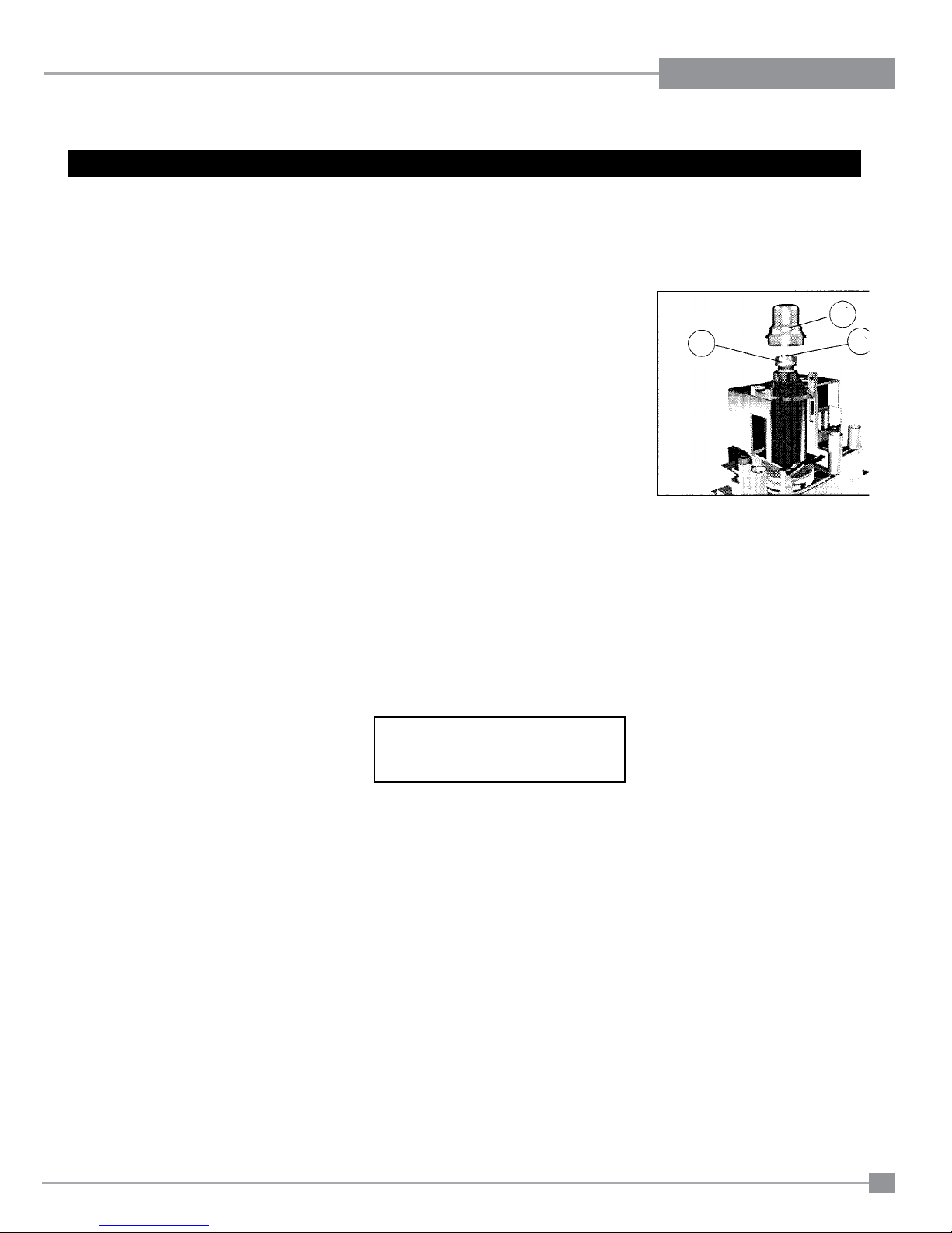
WARNING: To ensure the correct opera-
tion of the modulator it is necessary that
the plastic cap (A) is returned to its original
location.
13) Turn on gas supply and plug in power cord.
14) At the end of all setting and adjustment
operations, check electrical installation and
gas leaks.
15) Check operation of fl ame control.
B
Figure 1
A
C
9) Stick the conversion label "This unit has been
converted to "ULPG" over top of the serial
number decal.
10) Replace the yellow "NG" label with the red
"ULPG" label.
11) Reverse steps 6-2.
12) Adjusting the Outlet Pressure
All the adjustments must be carried out
in the following order:
Remove the modulator plastic cap (A) using
needle nose pliers.
Maximum pressure: Turn unit "ON" to it's
highest input rating by setting the burner switch
to "HIGH" Screw in the nut (B) to increase the
outlet pressure and screw it out to decrease
it. Use a 10 mm wrench.
NOTE: The outlet pressure must be set to
maximum 2.49 kPa.
WARNING: When adjusting maximum pres-
sure do not screw the nut in fully.
If unable to obtain 2.49kPa outlet,
check inlet pressure is adequate.
Damage may occur to the gas valve
if maximum pressure adjustment is
fully screwed in.
16) Check for proper fl ame appearance and
glow on logs.
Installer Notice:
These instructions must be left
with the appliance.
Regency IP28 Gas Inbuilt Fireplace
17
Page 18
INSTALLATION
IP28
OPTIONAL MODULAR FIREPLACE SOLUTION INSTALLATION
OPTIONAL MODULAR FIREPLACE SOLUTION INSTALLATION
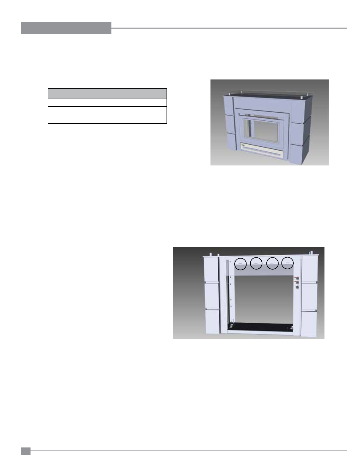
Follow these instructions to the install the Optional Modular Fireplace Solution
See Installation Manual for overall dimensions and clearances.
Before you begin:
Ensure the Modular Fireplace Solution (MFS) is positioned so the gas and electrical connections can enter from the bottom or the back.
Required components
IP28 unit
Modular Fireplace Solution (comes with faceplate
Venting Kit
1) Follow the installation instructions for the venting and termination as referenced in the installation manual. Please note: WHEN IP 28 IS INSTALLED
WITHIN THE MFS THE UNIT IS RAISED. ENSURE YOUR HOLE TO CENTER IS MARKED AND CUT ACCORDINGLY.
2) Once the hole is prepared to install the venting, place the MFS center of the hole and fl ush against the wall and position the gas line and electrical
accordingly within the MFS. Secure the MFS to the wall using the screws provided. See screw locations in diagram below.
Note: Front panel shown as transparent to show screw locations.
3) Ensure venting is secured to unit and slide unit carefully into the MFS. NOTE: SLIDE UNIT IN PARTIALLY TO ALLOW ACCESS TO CONNECT
GAS AND ELECTRICAL. Once gas and electrical are connected, slide unit in completely.
18
Regency IP28 Gas Inbuilt Fireplace
Page 19
IP28
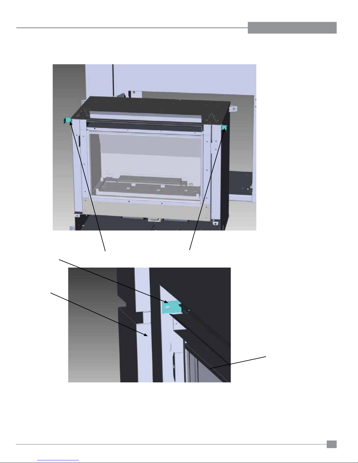
4) Secure unit to the MFS using the two securing brackets provided. See Below. Next, secure fl ue cowl to venting.
INSTALLATION
Securing brackets
Securing bracket
MFS
5) Install optional stainless inner panels and remote control if applicable.
See installation manual for detailed instructions. Install decorative log kit as referenced in the installation manual.
6) Install the faceplate as referenced in the installation manual, under slimline faceplate.
Unit
7) Ensure the proper gas pressure.
Regency IP28 Gas Inbuilt Fireplace
19
Page 20
INSTALLATION
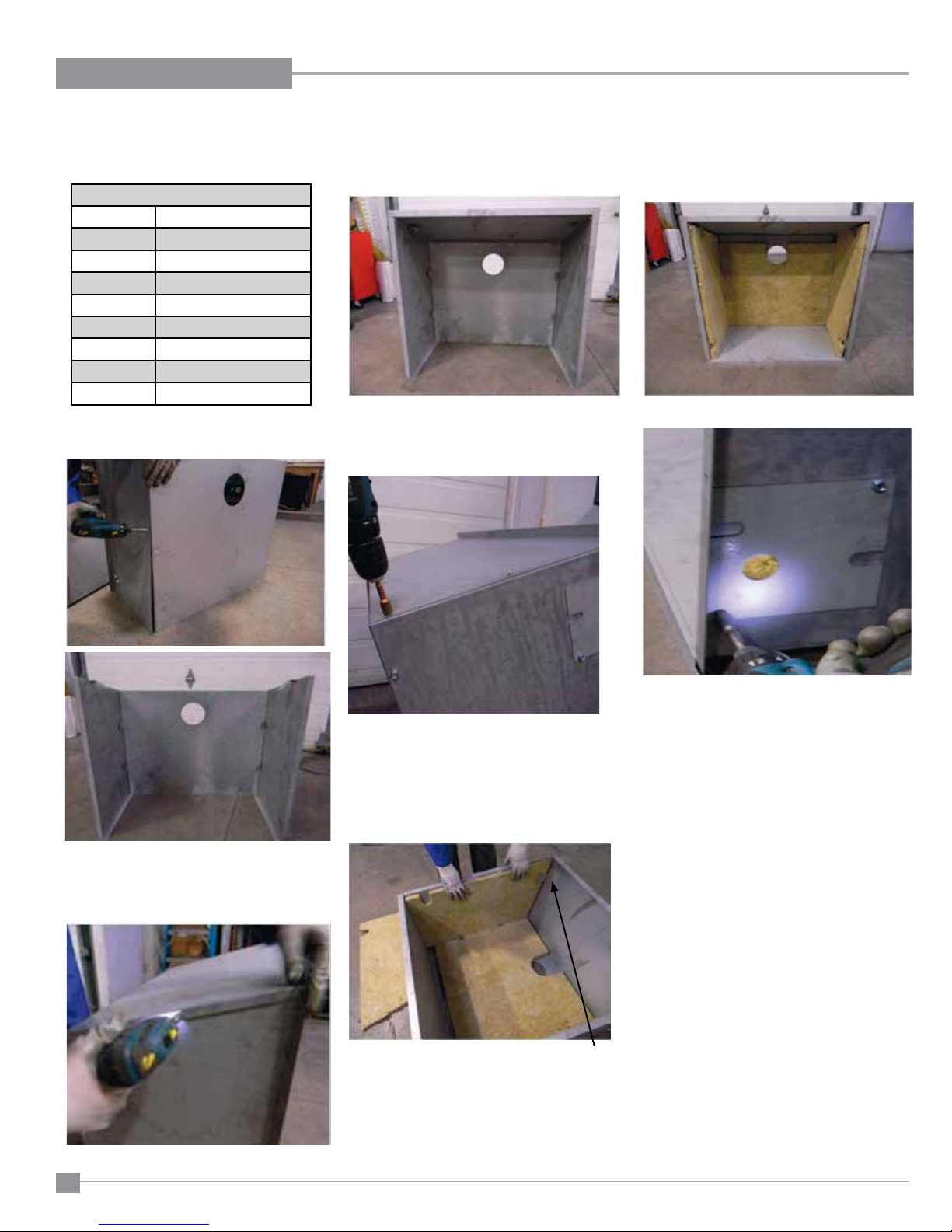
OPTIONAL WEATHER BOX INSTALLATION
IP28
OPTIONAL WEATHER BOX INSTALLATION
NOTE: The weather box to be installed ONLY in conjunction with the "Mock Fireplace Kit"
KIT # 456-940 Contains:
456-124 Cover External LH
456-125 Cover External RH
456-128 Cover External Top
456-129 Cover External Bottom
456-130 Cover External Back
440-420F Plate Gas Line Cover
456-126 Insulation Back
456-127 Insulation Sides
904-643 Screw 10 x 1/2 Hex
1. Attach the side to the back with 4 screws on
each side.
5. Add gas cover plate, if required.
3. Attach the bottom to the sides with 3 screws
on each side.
Ensure return edge is on the inside.
Side panels attached to back
2. Attach the top to the sides with 3 screws on
each side.
Attach bottom to sides
4. Install back insulation fi rst, when in place,
bend over 4 securing tabs. Install left and right
sides bending over three tabs each side to
secure.
Tab
Install insulation - secure by bending
tabs
6. With the weather box assembled, secure to
the outside wall with screws.
7. Ensure weather box is sealed against
weather/water ingress etc
8. Before installing unit, ensure fl ue length, gas
and electrical routing have all been considered.
9. Install unit.
20
Regency IP28 Gas Inbuilt Fireplace
Page 21
INSTALLATION
IP28
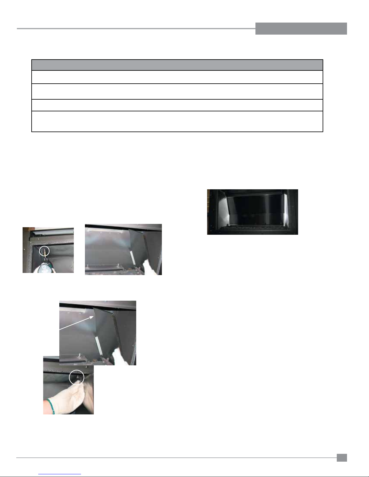
OPTIONAL STAINLESS STEEL INNER PANEL INSTALLATION
OPTIONAL STAINLESS STEEL INNER PANEL INSTALL
Before you start:
Stainless panels must be inspected for scratches and dimples prior to installation. All claims to be recorded at this time. Claims for
damage after installation will not receive consideration.
To protect the fi nish during installation and handling - cotton gloves MUST be worn at all times while handling the panels (even
when removing protective coating).
Stainless panels will discolor a little during normal operation. This is normal and should not be considered a defect.
All hand and fi nger marks MUST be cleaned off with a soft cloth and a stainless steel cleaner. Most stainless steel cleaners leave a
fi lm/residue on the surface of the panels. Use an ammonia based cleaner (ie. glass cleaner) to remove this fi lm before applying heat to
the unit. Failure to do this will result in burn stains on panels which you will be unable to remove. This is not a warranty item.
1) Remove the primary guard and faceplate. Unplug polarized plug
for the switches.. Refer to instructions in this manual.
2) Remove glass and glass retainers.
Refer to instructions in this manual for detailed instructions.
3) Remove all the logs if installed and set aside carefully.
4) Remove the two side brackets and screws (set aside) - then
remove the side panels by tilting the top in and lifting them out.
6) Secure the stainless panel with original bracket and screw - repeat
procedure on the opposite side.
7) Reinstall the logs, glass door, inner door frame with screen
and fi nally the faceplate. See manual for detailed instructions.
5) Orient the stainless side panels with the angled corner facing the
back of the fi rebox.
Angled corner
in panel
Final installation of optional stainless panels.
Regency IP28 Gas Inbuilt Fireplace
21
Page 22
INSTALLATION
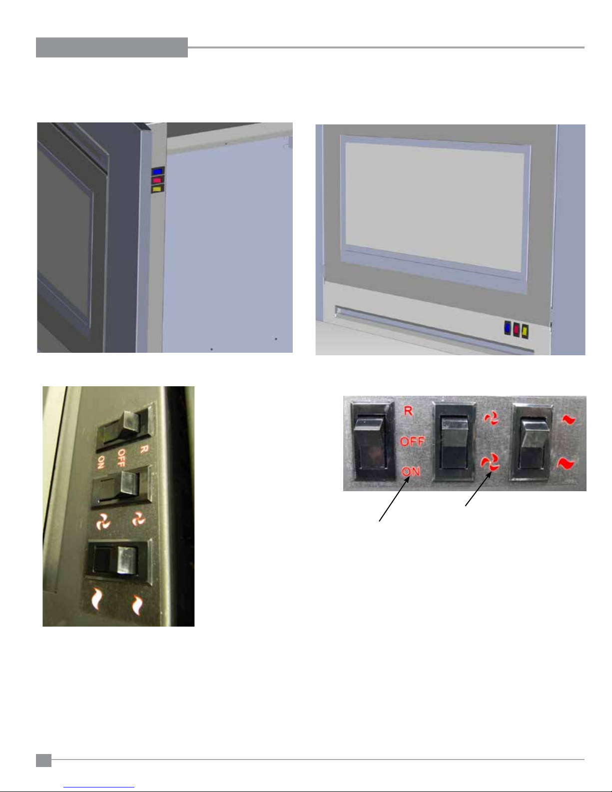
SWITCH OPERATION
Switch location - Contemporary Faceplate
Switch operation - Contemporary Faceplate
ON | OFF | REMOTE
HIGH | LOW (FAN)
HIGH | LOW (Mj)
Switch location - Slim line Faceplate
HIGH | LOW (Mj)
HIGH | LOW (FAN)
ON | OFF | REMOTE
Switch operation - Slim line Faceplate
22
Regency IP28 Gas Inbuilt Fireplace
Page 23
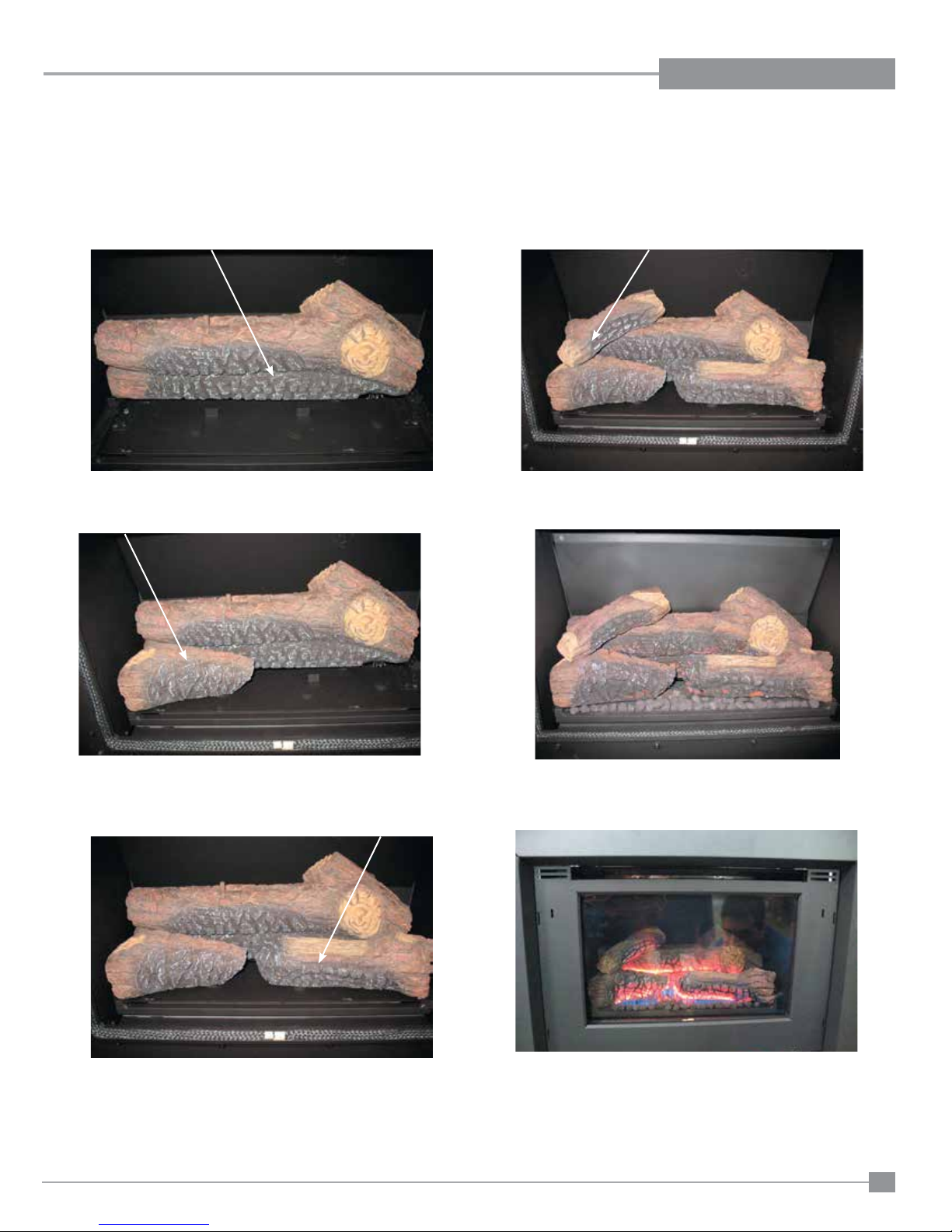
LOG SET INSTALLATION
IP28
LOG SET INSTALLATION
1) Install rear log (0113) Ensure proper pin location and positive position
on all logs.
INSTALLATION
4) Install top left cross log.
2) Install left front log (0115).
3) Install right front log (0115).
5) Place lava rocks on fi rebox base in front of logs - do not block
porting and spread out evenly.
6) Final install.
Regency IP28 Gas Inbuilt Fireplace
23
Page 24
INSTALLATION
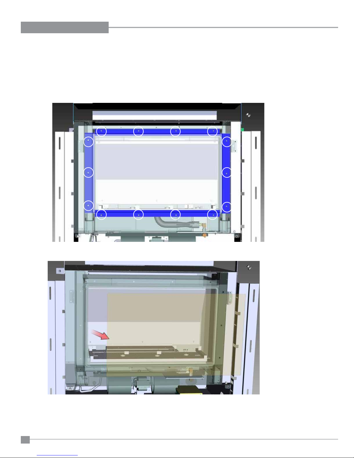
GLASS DOOR INSTALLATION
Before you start: Ensure power is off.
1) Remove the primary guard and faceplate. Unplug polarized plug for the switches.
2) Loosen 14 screws securing the glass retainers.
Remove as many retainers required to either lift or slide the existing glass out. Ensure glass does not dislodge
3) Carefully remove and replace the glass.
4) With new glass installed in correct position, reinstall all glass retainers and screws.
Ensure all screws are tightened to create a proper seal. Do not over tighten.
NOTE: Unit will not operate with glass removed
24
Regency IP28 Gas Inbuilt Fireplace
Page 25
INSTALLATION
IP28
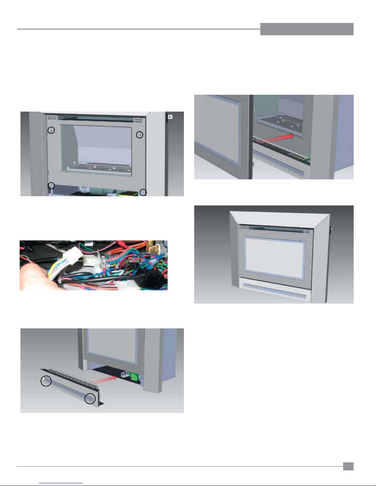
CONTEMPORARY FACEPLATE INSTALLATION
CONTEMPORARY FACEPLATE INSTALLATION
NOTE: If installing the Contemporary Faceplate with the mock fi replace adjust the framing tabs accordingly.
1) Line up faceplate with front of unit.
Install four (4) screws in locations shown below to secure faceplate
2) Hook up wire harness from faceplate to connection to under unit and
check gas connections.
4) Re install front frame.
5) Final install.
3) Reinstall bottom louver and install 2 screws in locations shown below.
Regency IP28 Gas Inbuilt Fireplace
25
Page 26
INSTALLATION
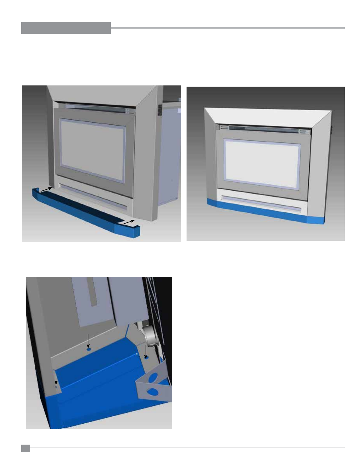
HEARTH TRIM INSTALLATION
1) Line up the hearth trim with the bottom of the fascia until it is flush with
the fascia.
3) From the backside of the fascia - secure the hearth trim with 3 screws
on each side in locations shown below.
26
Regency IP28 Gas Inbuilt Fireplace
Page 27
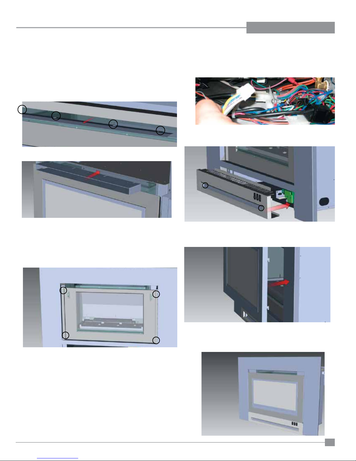
INSTALLATION
LOW PROFILE FACEPLATE INSTALLATION
IP28
SLIM LINE FACEPLATE INSTALLATION
NOTE: If installing the Low Profi le Faceplate with the mock fi replace - adjust the framing tabs accordingly
1) Remove the stabilizer bar by removing 4 screws - install the convention
air duct in the same location using the same 4 screws, see below.
3) Hook up wire harness from faceplate to connection to under unit and
check gas connections.
4) Reinstall bottom louver and install 2 screws in locations shown below
2) Install four (4) screws in locations shown below to secure faceplate
5) Re install front frame.
6) Final install.
Regency IP28 Gas Inbuilt Fireplace
27
Page 28
INSTALLATION
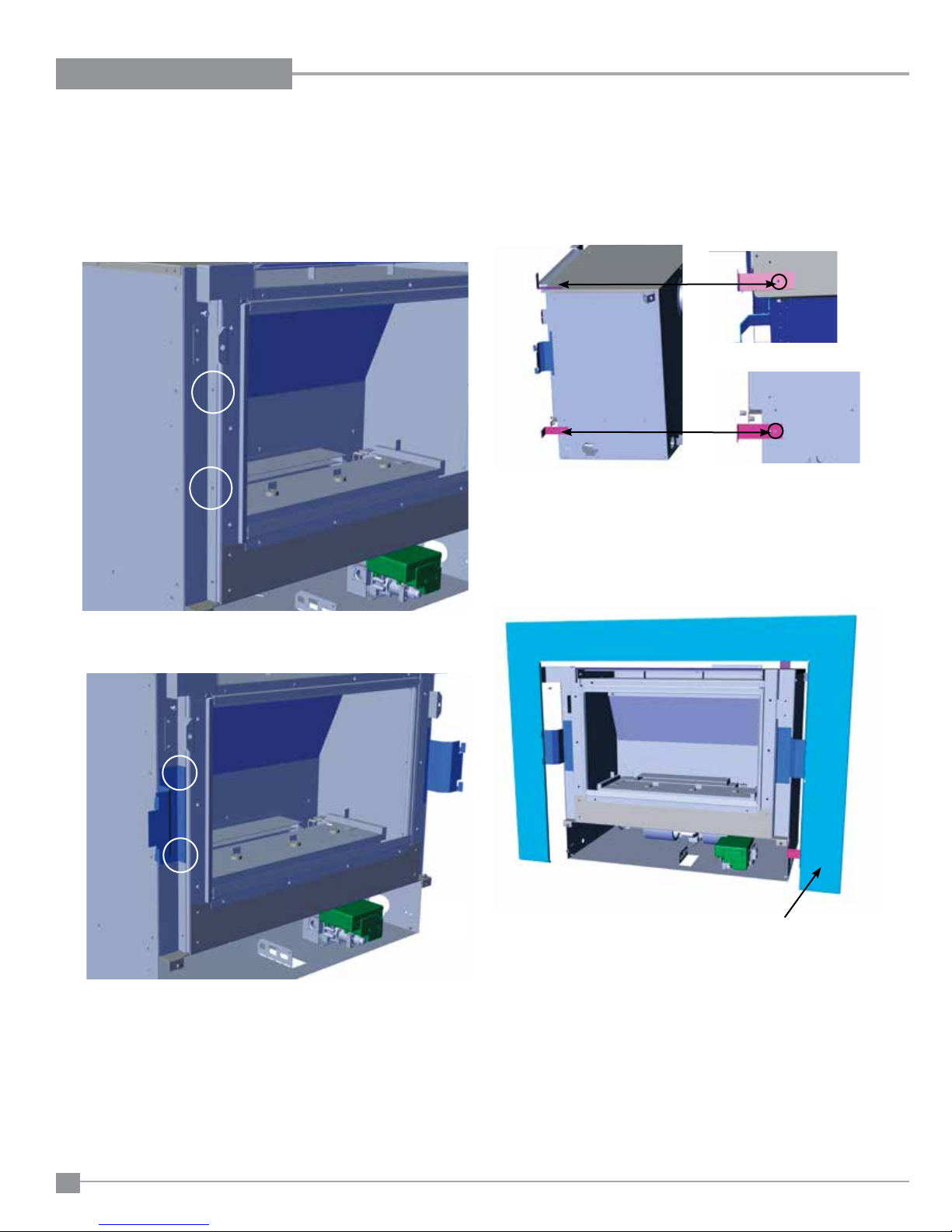
OPTIONAL INFILL PANEL INSTALLATION
IP28
OPTIONAL INFILL PANEL INSTALLATION
If required, an optional infi ll panel is available to cover larger openings.
1. Remove 2 screws on each side of the unit from locatiions shown below.
2. Install a mounting bracket on each side of the unit, in the same loca-
tion as where screws removed.
3. Install 4 support brackets, two on the side, and two on the top of the
unit as shown below.
Top Bracket: Use Front Screw Hole
Side Bracket: Use Back Screw Hole
NOTE: Support brackets are only required for masonary installations.
4. Hook the infi ll panel onto the brackets installed in Step 2.
28
Infi ll Panel
5. Please see Modular Faceplate instructions to complete installation.
NOTE: Infi ll panel is required for mock fi replace applications and optional
for masonry applications when installing Modular faceplate.
Regency IP28 Gas Inbuilt Fireplace
Page 29
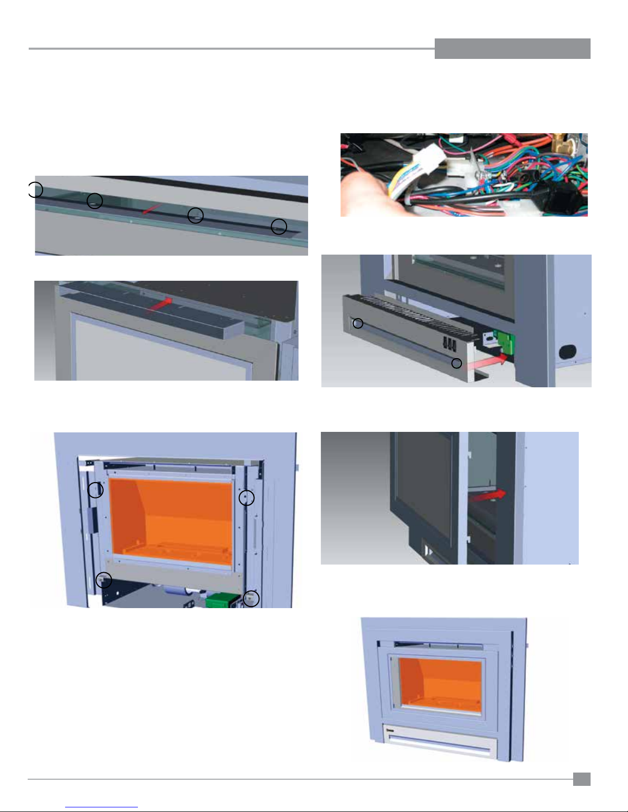
MODULAR FACEPLATE INSTALLATION
MODULAR FACEPLATE INSTALLATION
IP28
NOTE: If installing the Modular Faceplate with the mock fi replace application - adjust the framing tabs accordingly
1) Remove the stabilizer bar by removing 4 screws - install the convention
air duct in the same location using the same 4 screws, see below.
INSTALLATION
3) Hook up wire harness from faceplate to connection to under unit and
check gas connections.
4) Reinstall bottom louver and install 2 screws in locations shown below
2) Install four (4) screws in locations shown below to secure faceplate
5) Re install front frame.
6) Final install.
Regency IP28 Gas Inbuilt Fireplace
29
Page 30
INSTALLATION
FINAL CHECK
Before leaving this unit with the customer, the installer must ensure that the appliance is ring correctly. This includes:
1) Clocking the appliance to ensure the correct ring rate (rate noted on label) at 15 minutes.
2) If required, adjusting the primary air to ensure that the ame does not carbon. First allow the unit to burn for 15 min. to stabilize.
CAUTION
Any alteration to the product that causes sooting or carboning that results in damage to the exterior facia is not the responsibil-
ity of the manufacturer.
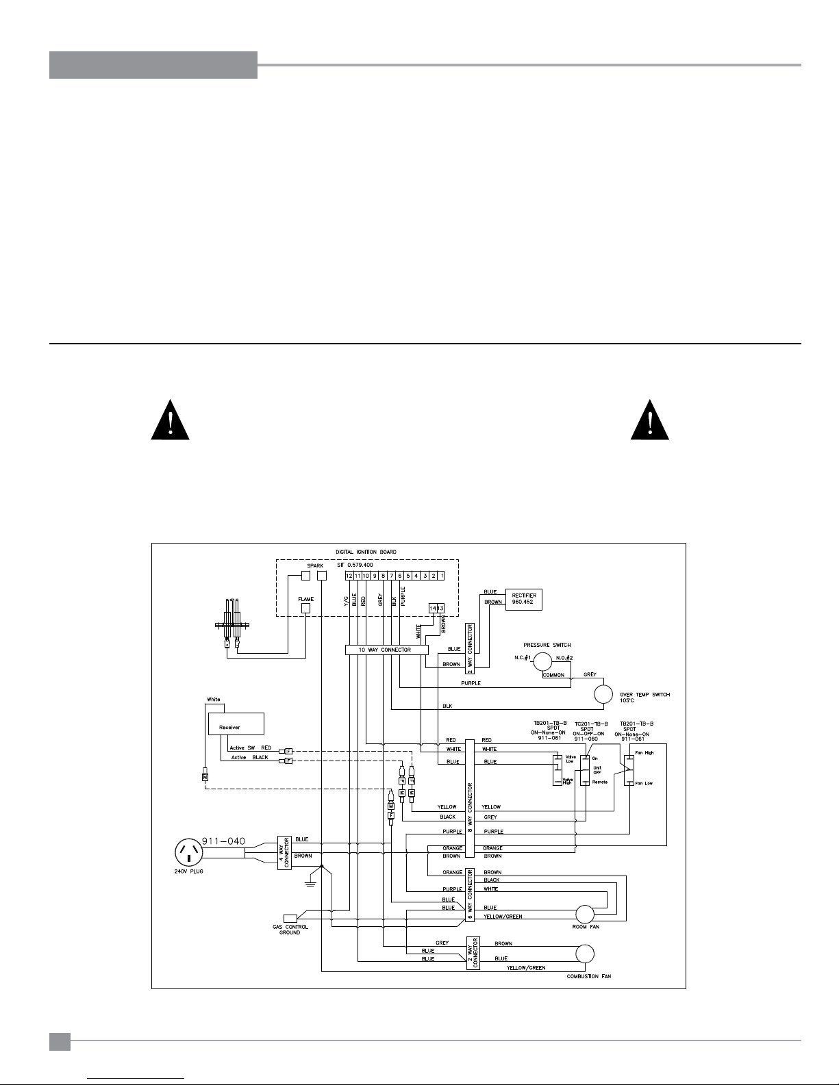
WARNING: 240V DISCONNECT POWER TO UNIT PRIOR TO WORKING ON ELECTRICAL COMPONENTS.
WIRING
Caution: Ensure that the wires do not
touch any hot surfaces and are away
from sharp edges.
This unit is polarity sensitive and will
not operate if polarity is incorrect.
STANDARD WIRING
CAUTION: Label all wires prior to disconnection
when servicing controls. Wiring errors can
cause improper and dangerous operation.
30
Regency IP28 Gas Inbuilt Fireplace
Page 31

OPERATING INSTRUCTIONS
INSTALLATION
OPERATING
INSTRUCTIONS
Before operating this appliance, proceed through
the following check list.
1) Read and understand these Instructions before
operating this appliance.
2) Check to see that all wiring is correct and
enclosed to prevent possible shock.
3) Check to ensure there are no gas leaks.
4) Make sure the glass door is in place. Never
operate the appliance with the door glass
removed.
5) Verify that all ueing and the cap is unob-
structed.
6) Verify log placement.
7) The unit should never be turned off and on
again without a minimum of a 2 minute wait.
8) When lighting the appliance, the inside of the
glass may fog up. This will burn off after a few
minutes of operation.
FIRST FIRE
The FIRST FIRE in your heater is part of the paint
curing process. To ensure that the paint is properly
cured, it is recommended that you burn your replace
for at least four (4) hours the rst time you use it
with the fan on.
When rst operated, the unit will release an odour
caused by the curing of the paint and the burning
off of any oils remaining from manufacturing. Smoke
detectors in the house may go off at this time. Open
a few windows to ventilate the room for a couple of
hours. The glass may require cleaning.
NOTE: When the glass is cold and the appliance
is lit, it may cause condensation and fog
the glass. This condensation is normal and
will disappear in a few minutes as the glass
heats up.
DO NOT ATTEMPT TO CLEAN THE GLASS
WHILE IT IS STILL HOT!
DO NOT BURN THE APPLIANCE WITHOUT
THE GLASS FRONT IN PLACE.
LIGHTING
INSTRUCTIONS
1) Locate the 3 way switch located on the face-
plate (refer to switch operation section in this
manual for location).
Manual Operation - Turn 3 way switch to ON
position, after approximately 60 seconds the
spark ignition system will spark for 5 seconds
to light the main burner. If the main burner
fails to light - repeat sequence.
Remote Operation - Turn 3 way switch to the
Remote position, locate Remote - press and
release ON/OFF button once. Wait approximately 60 seconds to light the main burner. If
the main burner fails to light repeat sequence.
SHUTDOWN
INSTRUCTIONS
Manual Operation - Turn 3 way switch to OFF
position.
REMOTE CONTROL
Use the Regency Remote Control Kit approved
for this unit. Use of other systems may void your
warranty.
Note: The remote must be coded into the unit before
it can be operated. See "Remote Control Installation
and Operating Instructions" manual supplied with
the remote control.
The remote control kit comes with a hand held
transmitter and a wall mounting plate.
1) Choose a convenient location, to the left side of
the valve, to mount the hand held transmitter,
protection from extreme heat is very important.
By using the wall mounting plate to house the
transmitter, the remote can also be used as a wall
thermostat.
Remote Operation - Press and release ON/
OFF button once or turn 3 way switch from
Remote position to OFF position.
Regency IP28 Gas Inbuilt Fireplace
3131
Page 32
OPERATING INSTRUCTIONS
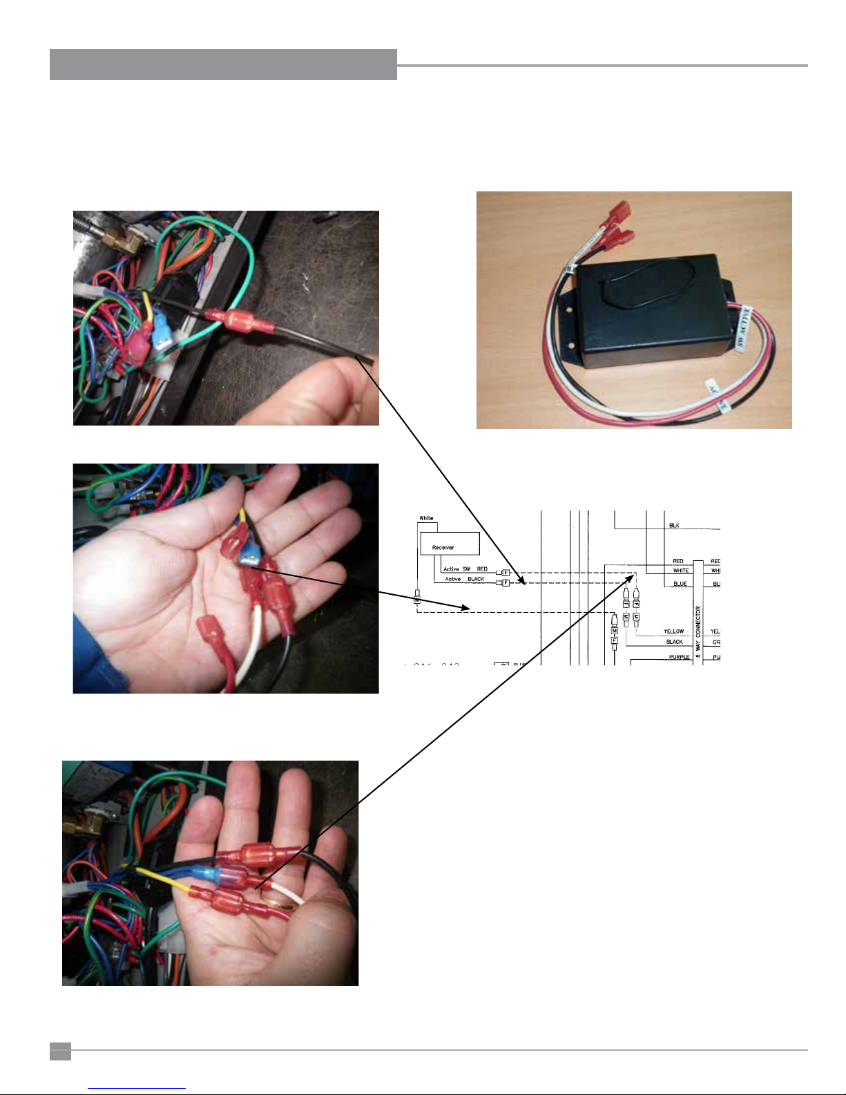
REMOTE RECEIVER INSTALLATION
Carefully remove blank spades from remote wires in heater.
1) Connect black to black.
2) Connect white to blue.
Once you connect the black wire, the other 2
wires are identied by the male-female connec-
tor.
Remote receiver
Place the receiver in the left hand side on the base of the heater.
Ensure the receiver aerial is not touching metal components.
32
32
Regency IP28 Gas Inbuilt Fireplace
Page 33
OPERATING INSTRUCTIONS
INSTALLATION
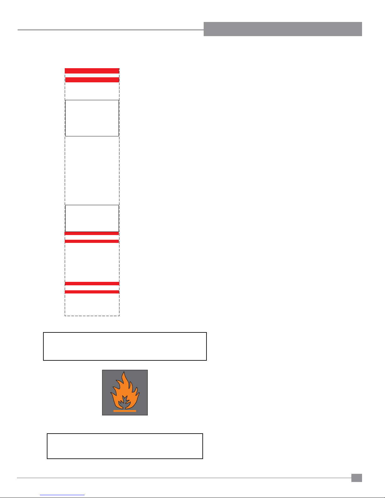
COPY OF LIGHTING INSTRUCTION PLATE
FOR YOUR SAFETY READ BEFORE LIGHTING
This appliance must be installed in accordance
with local codes, if any; if not,
follow the current CAN1-B149/ANSI Z 223.1
(Australia: AS5601-2004, New Zealand: NZS
WARNING: If you do not f ollow these
instructions exactly, a fi re or explosion
may result causing property damage,
personal injury or loss of life. Improper
installation, adjustment, alteration, service
or maintenance can cause injury or property
damage. Refer to the owner’s information
manual provided with this appliance. For
assistance or additional information consult
a qualifi ed installer, service agency or gas
supplier.
A) BEFORE LIGHTING smell all around the appliance
area for gas. Be sure to smell next to the fl oor because
some gas is heavier than air and will settle on the
fl oor.
WHAT TO DO IF YOU SMELL GAS
- Do not try to light any appliance
- Do not touch any electric switch, do not use
any phone in your building
- Immediately call your gas supplier from a
neighbors phone. Follow the gas supplier’s
instructions.
- If you cannot reach your gas supplier, call the fi re
B) Do not use this appliance if any part has been under
water. Immediately call a qualifi ed service technician
to inspect the appliance and to replace any part of
the control system and any gas control which has
been under water.
This appliance needs fresh air for safe operation and
must be installed so there are provisions for adequate
combustion and ventilation air.
CAUTION: Hot while in operation. Do not
touch. Severe Burns may result. Due to
high surface temperatures keep children,
clothing and furniture, gasoline and other
liquids having fl ammable vapors away. Keep
burner and control compartment clean.
See installation and operating instructions
accompanying appliance.
STOP! Read the safety information above on this
1) Ensure the power cord is plugged into the
2) Turn 3 way switch to ON position
3) After approximately 60 seconds the spark
ignition system will spark for 5 seconds to
4) If the main burner does not light, repeat step 2
1) Turn 3 way switch to OFF
2) Turn off all electric power to the unit if service
DO NOT SPRAY AEROSOLS IN THE VICINITY OF
THIS APPLIANCE WHILE IN OPERATION.
5261)
department.
LIGHTING INSTRUCTIONS
label.
power outlet and turned on.
light the main burner.
to restart.
TO TURN OFF GAS APPLIANCE
is to be performed.
DO NOT REMOVE THIS
INSTRUCTION PLATE
918-958
WARNING:
NORMAL OPERATING
SOUNDS OF
GAS APPLIANCES
It is possible that you will hear some sounds
from your gas appliance. This is perfectly normal
due to the fact that there are various gauges
and types of steel used within your appliance.
Listed below are some examples. All are normal
operating sounds and should not be considered
as defects in your appliance.
Fans:
.It is not unusual for the fan to make a "whirring"
sound when ON. This sound will increase or
decrease in volume depending on the speed
setting of your fan speed control.
This appliance is equipped with a combustion
and convection fan. These fans will operate as
soon a the appliance is turned on.
NOTE: This appliance will not operate without
the convection fan running at all times.
Burner Tray:
The burner tray is positioned directly under the
burner tube(s) and logs and is made of a different gauge material from the rest of the rebox
and body. Therefore, the varying thicknesses of
steel will expand and contract at slightly different
rates which can cause "ticking" and "cracking"
sounds. You should also be aware that as there
are temperature changes within the unit these
sounds will likely re-occur. Again, this is normal
for steel reboxes.
Gas Control Valve:
As the gas control valve turns ON and OFF, a
dull clicking sound may be audible, this is normal
operation of a gas regulator or valve.
Unit Body/Firebox:
Different types and thicknesses of steel will
expand and contract at different rates resulting
in some "cracking" and "ticking" sounds will be
heard throughout the cycling process.
RESETTING THE UNIT
"Appliances incorporating a live fuel effect (designed to oper-
ate with blue ames with slight yellow tips) may exhibit slight
carbon deposition."
Regency IP28 Gas Inbuilt Fireplace
If the appliance goes to 'lockout', the system
will have to be reset by unplugging or
pressing switch to OFF position.
*Important: Wait at least 5 min for any
unburned gas to clear before resetting the
appliance.
NOTE: Wait 2 minutes between reset
attempts.
3333
Page 34
OPERATING INSTRUCTIONS
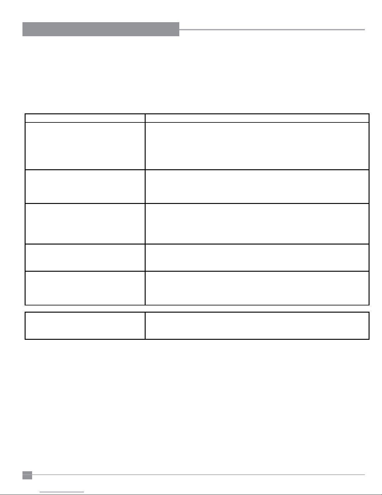
UNIT OPERATION ACTION REQUIRED
No gas to the burner The gas valve should open at the same time the ignition commences sparking. If
audible click when the pressure switch makes contact). Providing the spill switch
has continuity the electrode should spark and the gas valve open within 5 seconds
of the completion of the purge cycle.
All maintenance must be carried out by a licensed qualified service person
IT IS CRITICAL THAT THIS APPLIANCE IS EARTHED AND THAT THE ACTIVE AND NEUTRAL ARE NOT REVERSED
there is no gas to the burner, turn unit off. Connect manometer to inlet test point
on the gas valve and check static pressure. If O.K. turn unit on and check there is
no significant drop in the pressure. If O.K. connect manometer to outlet test point
of the gas valve, turn unit on and check outlet pressure is present whilst the spark is
being generated.
Unit sparks, main burner ignites after 5 seconds This can be caused by incorrect polarity.
spark continues even though main flame is present Check that the wall socket to the appliance has correct polarity. If an extension lead
is fitted check polarity of the lead. Check the polarity of the supply lead to the
appliance. NOTE: The above checks must be carried out by a qualified person
Combustion fan & Convection fan operate but no ignition module is in lockout. Switch off power to unit for 1 minute to reset module
ignition after approx 1 minute Then turn on again. Unit should ignite after purge time
NOTE: On initial light up this may occur a number of times until any residual air is
purged from the gas line through the burner system. It is essential the required
waiting time as stated in the manual is observed prior to attempting re ignition
After resetting ignition module, unit still not Turn burner switch to "ON", fans will operate within 5 secs, listen for audible "click" first from
operating after 1 minute ignition module, then from pressure switch.
If no "click' heard contact service agent
Confirm spark is produced when heater is turned on The ignition electrode should spark at the same time the gas control solenoid valve
opens(after approx 1minute purge time). At this point the spark electrode will
activate for up to 5 seconds. A blue spark can be seen when the heater ignition
process starts, Ensure the spark is present between the electrode and burner.
If no spark is produced Check the combustion fan & pressure switch are operating (there should be an
34
34
Regency IP28 Gas Inbuilt Fireplace
Page 35
MAINTENANCE
MAINTENANCE
INSTRUCTIONS
Any maintenance required accessing the glass
door of the unit must be performed by an authorized service person.
1) Always unplug the power cord before cleaning.
For relighting, refer to lighting instructions. Keep
the burner and control compartment clean by
brushing and vacuuming at least once a year.
When cleaning the logs, use a soft clean brush
as the logs are fragile and easily damaged.
2) Clean glass (never when unit is hot), appliance,
louvres, and door with a damp cloth. Never
use an abrasive cleaner. The gold louvres
(and optional gold door) may be scratched if
abrasives are used to clean them.
The heater is nished in a heat resistant paint
and should only be renished with heat resistant paint (not with wall paint). Regency uses
StoveBright Paint - Metallic Black #6309.
3) Make a periodic check of burner for proper
position and condition. Visually check the
ame of the burner periodically, making sure
the ames are steady; not lifting or oating. If
there is a problem, call an authorized service
person.
4) The appliance and ueing system must be
inspected before use, and at least annually, by
an authorized eld service person, to ensure
that the ow of combustion and ventilation air
is not obstructed.
During the annual service call, the burners
should be removed from the burner tray and
cleaned. Replace the embers - do not block
the burner ports.
INSTALLATION AND REPAIR SHOULD
BE DONE BY AN AUTHORIZED
SERVICE PERSON. THE APPLIANCE
SHOULD BE INSPECTED BEFORE
USE AND AT LEAST ANNUALLY BY A
PROFESSIONAL SERVICE PERSON.
MORE FREQUENT CLEANING MAY
BE REQUIRED DUE TO EXCESSIVE
LINT FROM CARPETING, BEDDING
MATERIAL, ETC. IT IS IMPERATIVE THAT
CONTROL COMPARTMENTS, BURNERS
AND CIRCULATING AIR PASSAGEWAYS
OF THE APPLIANCE BE KEPT CLEAN.
DUE TO HIGH TEMPERATURES, THE
APPLIANCE SHOULD BE LOCATED
OUT OF TRAFFIC AND AWAY FROM
FURNITURE AND DRAPERIES.
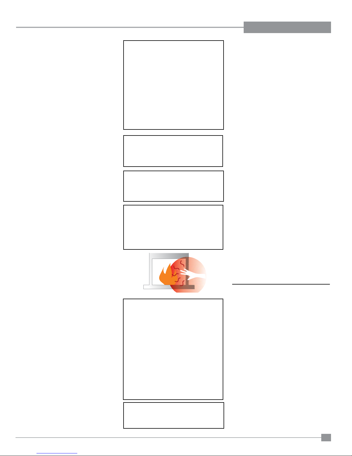
WARNING: FAILURE TO INSTALL THIS
APPLIANCE CORRECTLY WILL VOID
YOUR WARRANTY AND MAY CAUSE A
SERIOUS HOUSE FIRE.
CHILDREN AND ADULTS SHOULD BE
ALERTED TO THE HAZARDS OF HIGH
SURFACE TEMPERATURES, ESPECIALLY THE FIREPLACE GLASS, AND
SHOULD STAY AWAY TO AVOID BURNS
OR CLOTHING IGNITION.
The unit should never be used with broken logs.
Unplug the power cord and allow the unit to cool
before opening door to carefully remove the logs.
If for any reason a log should need replacement,
you must use the proper replacement log. The
position of these logs must be as shown in the
diagram under Log Installation.
Note: Improper positioning of logs may
create carbon build-up and will alter
the unit’s performance which is not
covered under warranty.
DOOR GLASS
REPLACEMENT
Your Regency stove is supplied with high temperature, 5 mm Neoceram ceramic glass that
will withstand the highest heat that your unit will
produce. In the event that you break your glass
by impact, purchase your replacement from an
authorised Regency dealer only, and follow our
step-by-step instructions for replacement.
WARNING: do not operate appliance
with the glass front removed, cracked
or broken. Replacement of the glass
should be done by a licensed or authorised service person.
Flush Glass Replacement
Slide old glass out of the side frames and replace
with new glass.
5) Keep the area near the appliance clear and
free from combustible materials, gasoline and
other ammable vapours and liquids.
6) Verify proper operation after servicing.
Regency IP28 Gas Inbuilt Fireplace
YOUNG CHILDREN SHOULD BE CAREFULLY SUPERVISED WHEN THEY ARE
IN THE SAME AREA AS THE APPLIANCE. TODDLERS, YOUNG CHILDREN
AND OTHERS MAY BE SUSCEPTIBLE
TO ACCIDENTAL CONTACT BURNS. A
PHYSICAL BARRIERS IS RECOMMENDED IF THERE ARE AT RISK INDIVIDUAL
IN THE HOUSE. TO RESTRICT ACCESS
TO A FIREPLACE OR STOVE, INSTALL
AN ADJUSTABLE SAFETY GATE TO
KEEP TODDLERS, YOUNG CHILDREN
AND OTHER AT RISK INDIVIDUALS OUT
OF THE ROOM AND AWAY FROM HOT
SURFACES.
CLOTHING OR OTHER FLAMMABLE
MATERIAL SHOULD NOT BE PLACED
ON OR NEAR THE APPLIANCE.
GLASS GASKET
If the glass gasket requires replacement use
glass gasket (Part # 936-233).
35
Page 36
MAINTENANCE
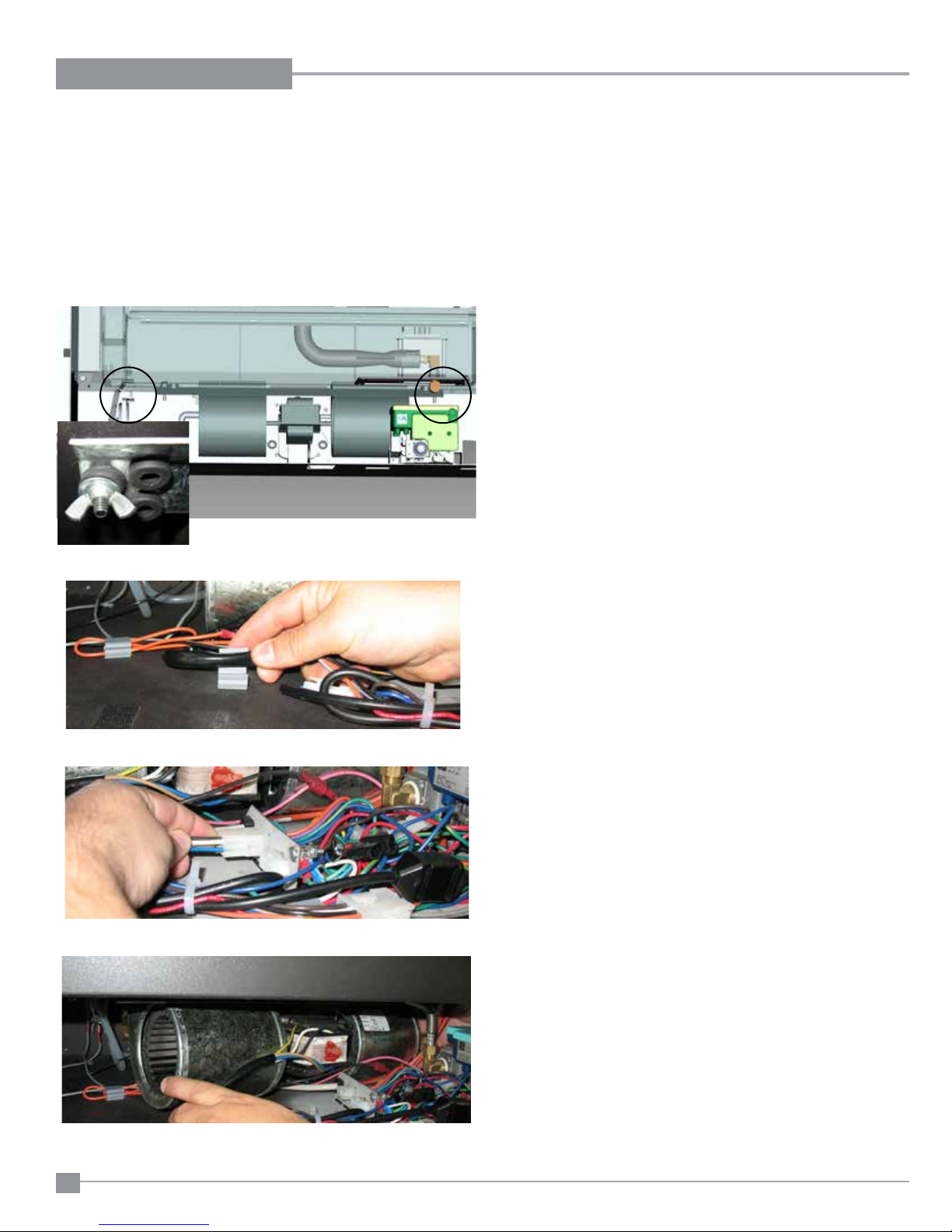
CONVECTION FAN REPLACEMENT
Before you start:
Ensure all power is turned off.
1) Turn the unit off and allow it to cool to room temperature,
2) Unplug or disconnect power source to stove.
3) Open the bottom louvre.
4) Remove 2 wing nuts + washers securing fan - locations shown below.
5) Unclip wires from base of unit and unplug fan.
8) Reverse steps to reinstall.
NOTE: It is essential that the two washers are re-tted to the fan mounting
bolts prior to tting the wing nuts.
6) Disconnect polarized plug.
7) Manoeuvre fan from base of unit and replace.
36
Regency IP28 Gas Inbuilt Fireplace
Page 37
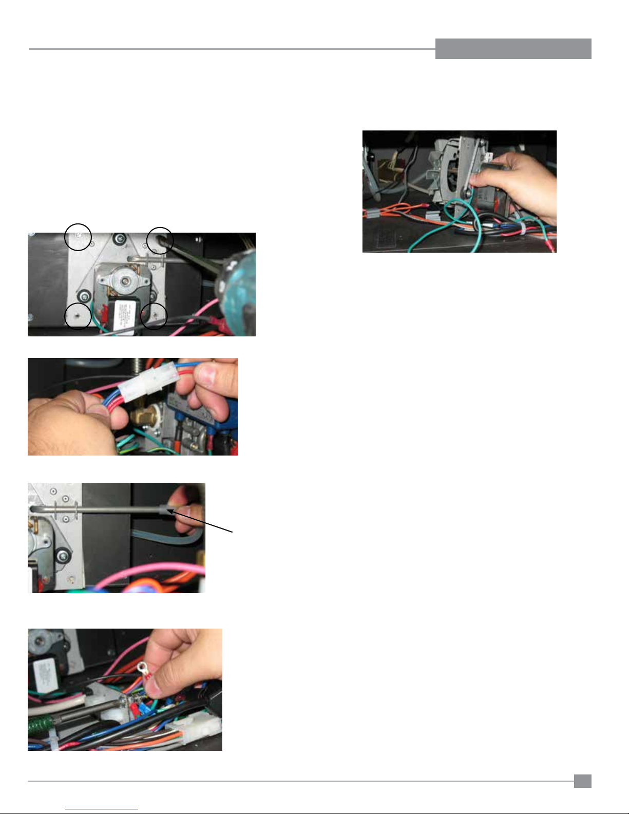
COMBUSTION FAN REPLACEMENT
MAINTENANCE
Before you start:
Ensure all power is turned off.
1) Turn the unit off and allow it to cool to room temperature,
2) Unplug or disconnect power source to stove.
3) Open the bottom louvre.
4) Remove convection fan - see previous page.
5) Remove 4 screws to release fan.
6) Disconnect polarized plug.
8) Manoeuvre fan from base of unit and replace.
9) Reverse steps to reinstall.
7) Disconnect tubing from right side of fan.
8) Disconnect ground wire.
Tubing
Regency IP28 Gas Inbuilt Fireplace
37
Page 38
PARTS LIST
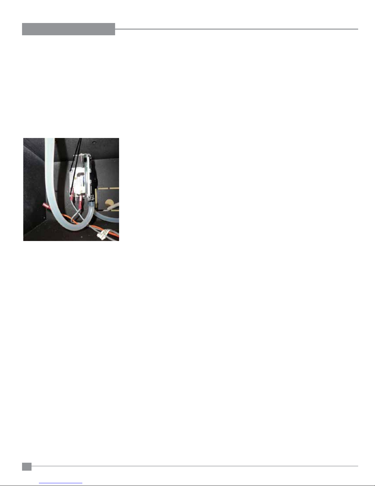
PRESSURE SWITCH REPLACEMENT
Before you start
Ensure all power is turned off.
1) Disconnect wire leads and tubing on the switch.
NOTE: It is important to label wires and hose connections to ensure the new switch is hooked up in
the same manner.
2) Remove the two screws on the mounting bracket.
Remove 2 screws
3) Slide switch out to the left side.
4) Remove switch and replace.
5) Reverse steps to complete installation.
38
Regency IP28 Gas Inbuilt Fireplace
Page 39
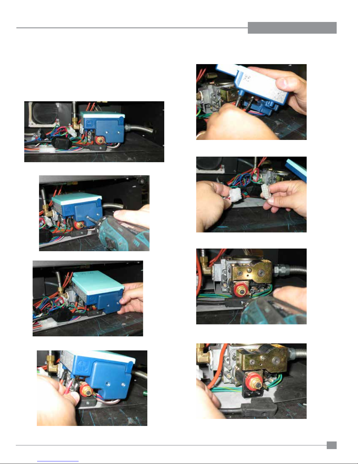
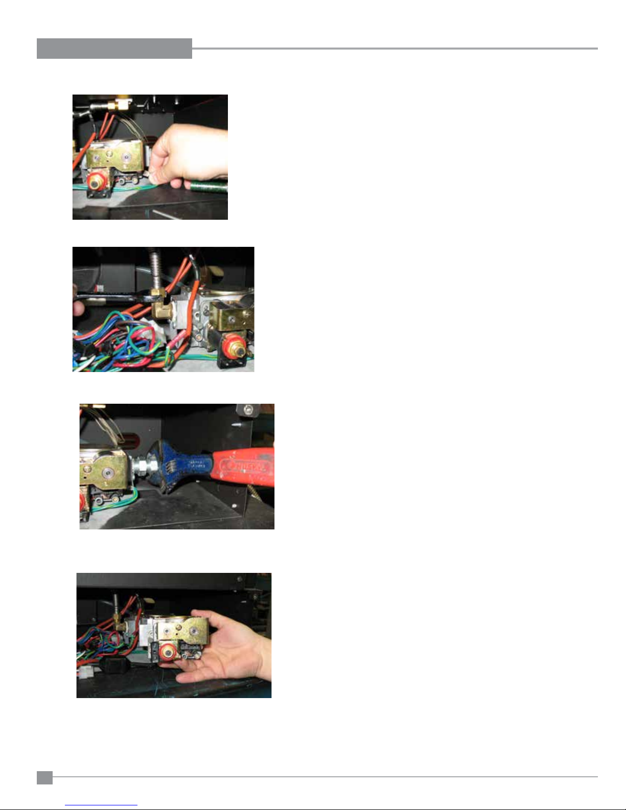
VALVE ASSEMBLY REPLACEMENT
Before you start:
Ensure all power is turned off.
1) Turn the unit off and allow it to cool to room temperature,
2) Unplug or disconnect power source to stove.
3) Open the bottom louvre to access valve.
4) Remove screw in location shown below to release valve cover.
MAINTENANCE
6) Disconnect wires.
6) Disconnect wire harness plug.
5) Partially lift out valve cover.
7) Remove screw from rectier,
8) Unplug rectier from valve.
Regency IP28 Gas Inbuilt Fireplace
39
Page 40
MAINTENANCE
9) Disconnect ground wire from valve.
.
10) Disconnect connection from valve to burner.
11) Disconnect connection from valve to gas outlet.
12) Remove valve and replace.
13) Reverse steps to reinstall.
40
Regency IP28 Gas Inbuilt Fireplace
Page 41
MAIN ASSEMBLY
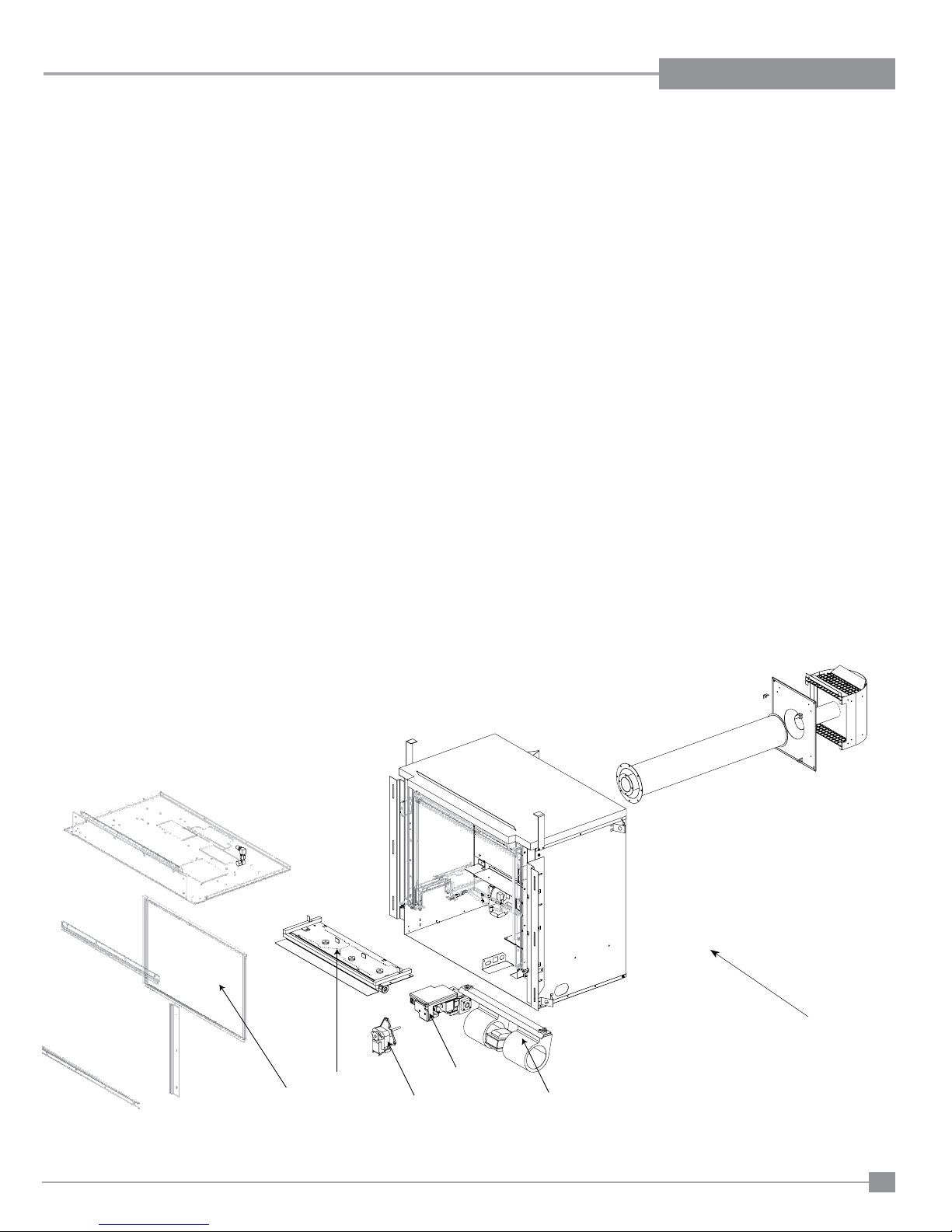
Part # Description Part # Description
1) 911-056/P Fan Combustion 240 Volt 50hz EU
2) 911-057/P Blower 240 Volt Convection
456-008 Tube Sensing Combustion Fan IP28
910-082 Ignition Direct Spark Assy Electronic
456-005 Gasket Combustion Fan IP28
456-004 Gasket Valve Tray IP28
PARTS LIST
W190615 Thermodisc** 105C
3) 456-968 LPG Conversion Kit**
4) 456-574/P Valve Assembly NG
456-578/P Valve Assembly LP
5) 911-064 Valve NG/LP 843 Sigma
6) 940-367/P Glass Neoceram Flush IP28
7) 456-525 Burner Assembly NG C/w Cap IP28
456-091 Baffle Plate IP28
911-040 Power Cord Assembly 240V IP28
456-001 Grate Assembly IP28
8) 456-044/F Bracket side flange right / IP28
456-049/F Bracket side flange left / IP28
911-047 Silicone Tubing
936-232 Gasket Rope
904-658 Inlet Flex Line Gas SS Steel 24 inch
910-088 Wire ECS Module Spark (Red)
910-089 Wire ECS Module Flame (Red)
911-041 Wire Harness Ignition Module IP28
911-042 Wire Harness Valve Rectifier IP28
911-044 Wire Harness Main Control IP28
911-059 Pressure Switch
911-062 Step Modular Plug Sit
911-063 Ignition Board 45 Sec. Sit
936-232 Door glass gasket (per 305mm)
456-930 Log Set IP28
918-938 Manual
*Not available as a replacement part.
** Part not shown.
6
Regency IP28 Gas Inbuilt Fireplace
8
7
4
1
2
41
Page 42
PARTS LIST
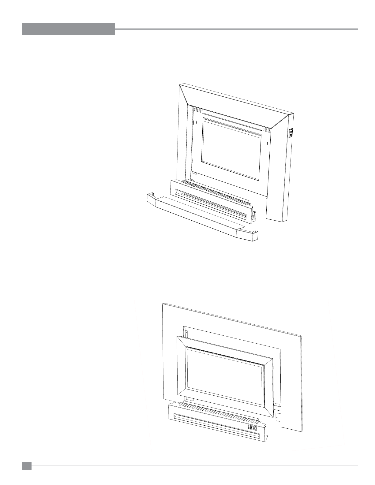
CONTEMPORARY FACEPLATE ASSEMBLY
Part # Description
14) 456-914 Faceplate & Trim Complete - Regular
* Faceplate Side Right IP28
* Faceplate Side Left IP28
* Faceplate - Top IP28
* Plate Backing Faceplate IP28
911-043 Wire Harness Control Switch IP28
911-060 Switch Rocker TC201-TB-B On/Off/On
911-061 Switch Rocker TB201-TB-B On/None/On
*Not available as a replacement part.
SLIM LINE FACEPLATE ASSEMBLY
Part # Description
- Door Bottom Access Slim F/P IP28
* Frame Front Slim Faceplate IP28
* Faceplate Front IP28
911-043 Wire Harness Control Switch IP28
911-060 Switch Rocker TC201-TB-B On/Off/On
911-061 Switch Rocker TB201-TB-B On/None/On
*Not available as a replacement part.
42
Regency IP28 Gas Inbuilt Fireplace
Page 43

WARRANTY
Regency® Fireplace Products are designed with reliability and simplicity in mind. In addition, our internal Quality Assurance Team carefully inspects each unit thoroughly
before it leaves our door. Regency® is pleased to extend this limited lifetime warranty to the original purchaser of a Regency® Product. Regency® will repair or replace
goods free of charge in the event of defects arising from faulty materials or workmanship in accordance with the warranty terms in relation to Denitions, Warranty
Conditions and Exclusions stated in this document.
The benets to the consumer given by this warranty are in addition to all other rights and remedies of the consumer under a law in relation to the goods or services to which the
warranty relates.
Our goods come with the guarantees that cannot be excluded under the Australian Consumer Law. You are entitled to a replacement or refund for a major failure and for compensation
for any other foreseeable loss or damage. You are also entitled to have the goods repaired or replaced if the goods fail to be of acceptable quality and the failure does not amount
to a major failure.
The Warranty: Lifetime
Covered under the agreement are the following components: The combustion chamber, heat exchanger, burner tubes/pans, logs, glass crystals, ceramic spa stones, pebbles,
brick panels and gold plating (against defective manufacture only) are covered under the Limited Lifetime Warranty for ve (5) years for parts and labour and parts only thereafter.
External casting, surrounds and grills are covered against cracks and warps resulting from manufacturer defects, parts and labour for one (1) year from the date of purchase and
parts only thereafter.
Regency Fireplace Products is not liable for freight or labour on any gas appliance replaced in the eld.
Special Finishes - One year on stainless steel panels, nickel overlays, nickel faceplates, brushed nickel and antique copper full screens and doors. You can expect some changes in
color as the product "ages" with constant heating and cooling. FPI warranties the product for any manufacturing defects on the original product. However, the manufacturers warranty
does not cover changing colors and marks, ie. nger prints, etc applied after the purchase of the product. Damage from the use of abrasive cleaners is not covered by warranty.
Electrical components such as fans, switches, ignition modules, wiring, thermodiscs, remote control, thermopiles, thermocouples and gas valves are covered for one year for parts
and labour from the date of purchase.
The warranty on brass parts is for one year, no labour. The brass is not warranted against tarnishing.
Repair/replacement parts purchased by the consumer from Regency® after the original coverage has expired on the unit will carry a 90 day warranty valid with a receipt only. Any
item shown to be defective will be repaired or replaced at our discretion. No labour coverage is included with these parts.
Conditions:
All installations must be performed by a qualied gas tter and installed according to all applicable local and national codes. Also, all service work must be carried out by a qualied
gas service person provided by the selling dealer. It is the responsibility of the installer to ensure that the appliance is ring as per rating plate. Any part or parts of this unit which in
our judgement show evidence of such defect will be repaired or replaced at Regency
to the distributor or agent Transportation Prepaid, if requested. In areas where there is not an approved service agent or the closest approved service agent is situated more than
thirty (30) kilometres from the installation, Regency is not obliged to arrange warranty repairs and travel and/or additional labour charges will apply.
Porcelain/Enamel - Absolute perfection is neither guaranteed nor commercially possible. Any chips must be reported and inspected by an authorised dealer within three days of
installation. Reported damage after this time will be subject to rejection.
It is the general practice of Regency
evaluated fro manufacturer defect.
At all time Regency reserves the right to inspect product in the eld which is claimed to be defective.
All claims must be submitted to Regency® by authorised selling dealers. It is essential that all submitted claims provide all of the necessary information including customer name,
purchase date, serial #, type of unit, problem, and part or parts requested, without this information the warranty will be invalid.
Exclusions:
This limited Lifetime Warranty does not extend to or include paint, door or glass gasket or trim. It does not cover installation and operational related problems such as over-ring,
down drafts or spillage caused by environmental conditions, nearby trees, buildings, hilltops, mountains, inadequate ueing or ventilation, excessive offsets, negative air pressures
caused by insufcient make up air, mechanical systems such as furnaces, fans, clothes dryers etc.
Embers, rockwool, gaskets, door handles and paint are not covered under the terms of this warranty policy.
Regency® will not be liable for acts of God, or acts of terrorism, which cause malfunction of the appliance.
Performance problems due to operator error will not be covered by this warranty policy.
The warranty does not extend to any part or parts which show evidence of misuse or abuse, neglect, accident, lack of maintenance, or improper installation.
Products made by other manufacturers and used in conjunction with the operation of this appliance without authorisation from Regency
Regency shall in no event be liable for any special, indirect consequential damages of any nature whatsoever which are in excess of the original purchase price of the product. Any
alteration to the unit which causes sooting or carboning that results in damage to the exterior facia is not the responsibility of Regency Fireplace Products.
SUBJECT TO CHANGE.
®
to charge for larger, higher priced replacement parts and issue credit once the replaced component has been returned to Regency and
DISTRIBUTORS: Western Australia Eastern Australia
®
's option, through an accredited distributor or agent provided that the defective part be returned
®
, may nullify your warranty on this product.
Air Group Australia
28-30 Division St.
Fireplace Products Australia PTY. Ltd.
1-3 Conquest Way
Welshpool, WA 6106 Hallam, VIC 3803
08 9350 2200 03 9799 7277
Regency IP28 Gas Inbuilt Fireplace
NOTE: PLEASE RETAIN YOUR INVOICE AS PROOF OF PURCHASE FOR WARRANTY VERIFICATION
INCORRECT INSTALLATION OR GAS PRESSURE SETTINGS ARE NOT COVERED BY WARRANTY
A SERVICE OR CALLOUT FEE WILL BE CHARGED IN THESE CIRCUMSTANCES.
43
Page 44
Register your Regency® warranty online
www.regency-re.com.au
Reasons to register your product online today!
• View and modify a list of all your registered products.
• Request automatic email notication of new product updates.
• Stay informed about the current promotions, events, and special
offers on related products.
• Help assure you get the most out of your warranty.
• Eliminate confusion and frustration if warranty** service is required in
the future.
** Proof of purchase required at time of warranty request.
Installer: Please complete the following information
Dealer Name & Address: ______________________________________________
___________________________________________________________________
Installer: ___________________________________________________________
Phone #: ___________________________________________________________
Date Installed: ______________________________________________________
Serial No.: __________________________________________________________
© Copyright 2015, FPI Fireplace Products International Ltd. All rights reserved.
Printed in Canada
 Loading...