

Page 1
Owners &
Installation
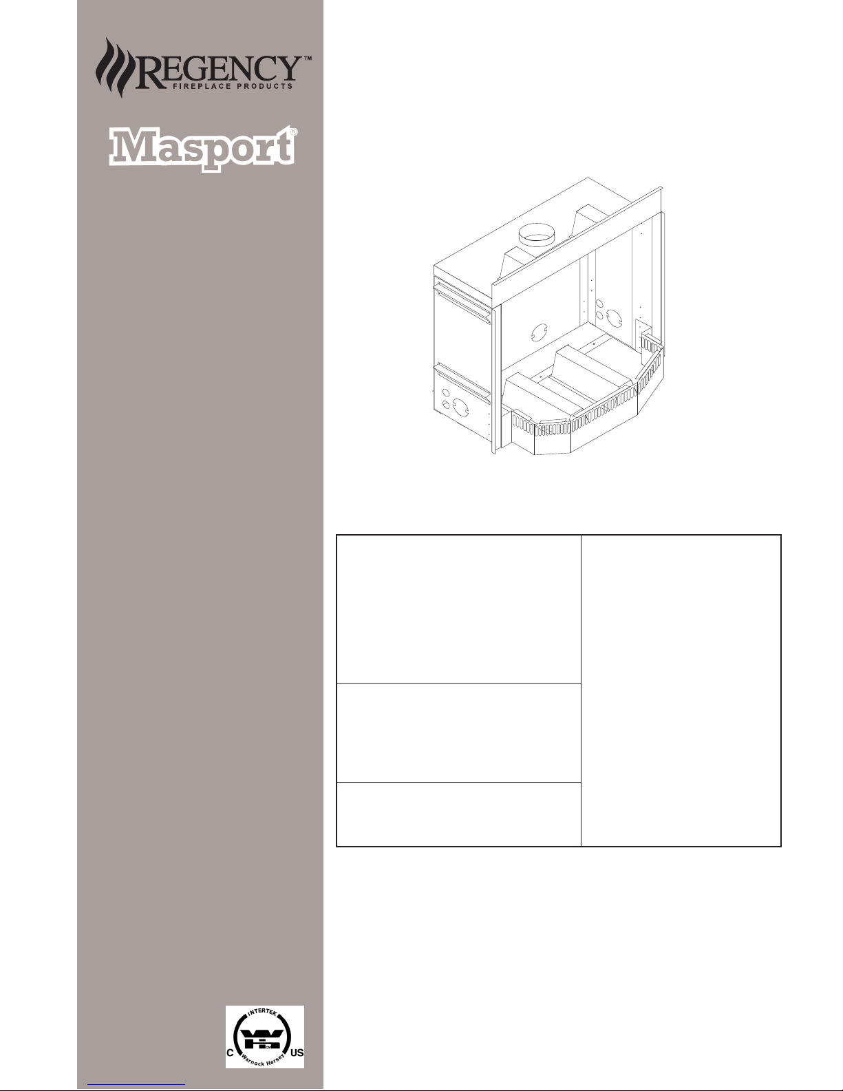
U41/I41 GAS INSERT
ZERO CLEARANCE KIT
KIT # 660-900
Manual
Tested by:
Warnock Hersey:
PLEASE KEEP THESE INSTRUCTIONS FOR
FUTURE REFERENCE
WARNING:
Improper installation, adjustment,
alteration, service or maintenance
can cause injury or property damage. Refer to this manual. For
assistance or additional information
consult an authorized installer, service agency or the gas supplier.
FOR YOUR SAFETY
Do not store or use gasoline or other
flammable vapours and liquids in
the vicinity of this or any other appliance.
Installation and service must be performed by an authorized installer,
service agency or the gas supplier.
FPI Fireplace Products International Ltd.
6988 Venture St., Delta, B.C.
Canada, V4G 1H4
Australian Heating Distributors
10/46 James St.,
Guildford, Western Australia 6055
908-427 01/16/04
FOR YOUR SAFETY
What to do if you smell gas:
- Do not try to light any
appliance
- Do not touch any electrical switch: do not use any
phone in your building.
- Immediately call your gas
supplier from a neighbour's phone. Follow the
gas supplier's instructions.
- If you cannot reach your
gas supplier, call the fire
department.
Masport Head Office - Australia
54 Boundary Rd. Braeside
P.O. Box 553
Mordialloc 3195
Ph. (03) 9586-7777
Fax. (03) 9586-2980
Masport Head Office - New Zealand
1-37 Mt Wellington Hwy.Panmure,
P.O. Box 14349
Auckland 6.
Ph. (9) 570-9009
Fax. (9) 527-1294
Page 2
LISTINGS AND CODE APPROVALS
This gas component has been tested in accordance with National Safety Standards, and has been certified by Warnock Hersey
for installation and operation in the United States, Canada, Australia, and New Zealand as described in these Installation and
Operating Instructions.
Check with your local building code agency before you begin your installation to ensure compliance with local codes, including
the need for "permits" and follow-up inspections. If any problems are encountered regarding code approvals, or if you wish
clarification on any of the instructions contained here, contact your local dealer.
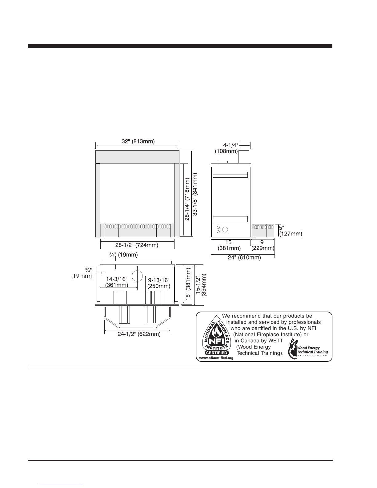
U41/I41 Zero Clearance Kit Specifications
Using Kit# 660-900 you can convert the Gas Insert models U41 and
I41 into highly efficient heat producing Zero Clearance Fireplaces.
REQUIRED PARTS
Included with Kit:
1 660-908 Main Body Assembly
1 660-906 Front Base Assembly
Sold Separately:
1 660-911 Zero Clearance Faceplate
44-3/8"(1127mm) W x 33-5/16"(846mm) H
2
GENERAL INFORMATION
This kit consists of factory built parts that require minimal assembly
to form the Zero Clearance enclosure for the U41/I41 Gas Insert.
The enclosure can then be fixed into a framed combustible construction, and a standard "B-vent" installed on the assembly for the
required venting. The insert can be installed later.
The faceplate will normally overlap on top of the finished wall. The
base of the Zero Clearance Kit can be installed directly on
carpeting, tile or any flooring material; however, the hearth if
installed in front of the unit requires special protection as described
in the "Hearth" section on page 4.
U41/I41 Gas Insert Zero Clearance Kit
Page 3
INSTALLATION
CLEARANCES TO COMBUSTIBLES
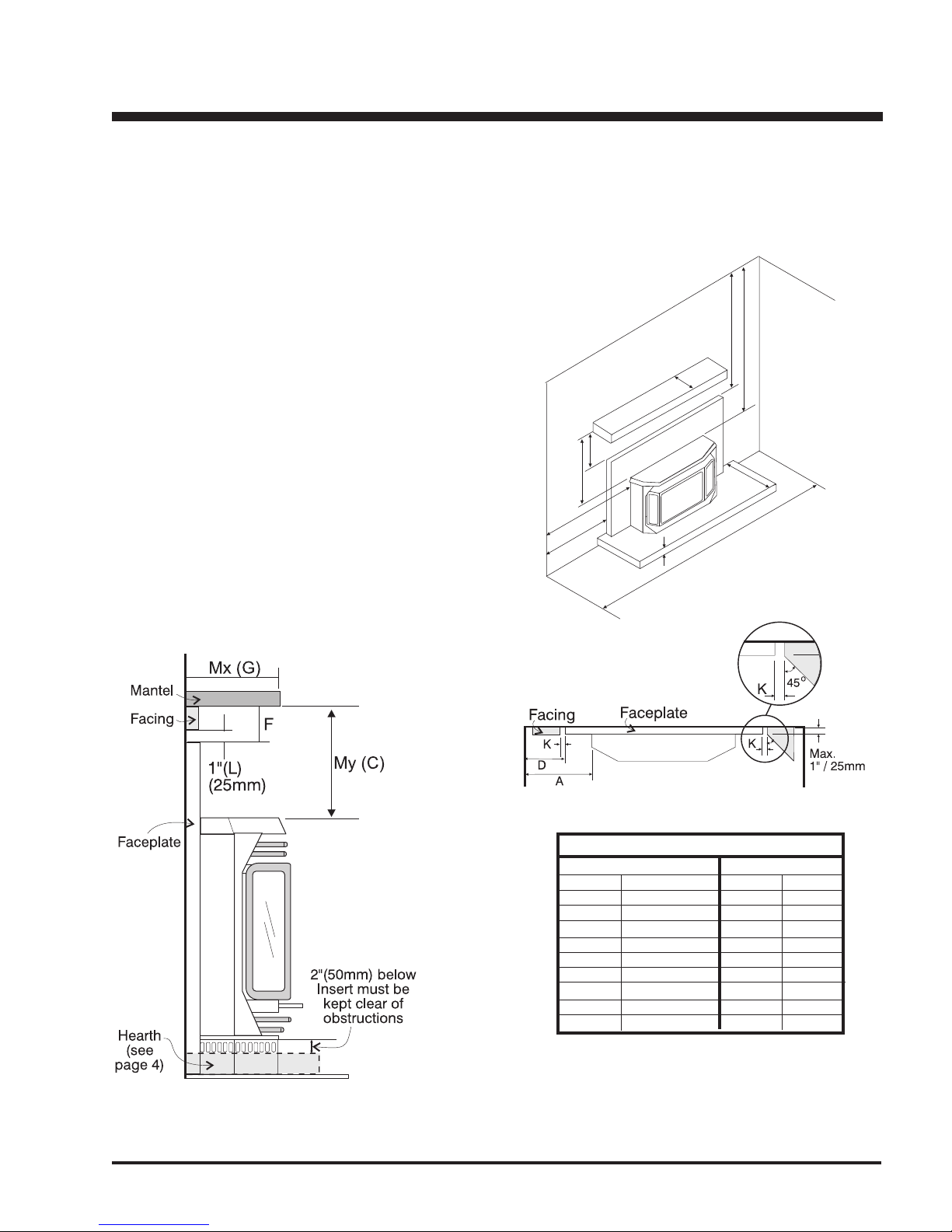
The clearances for the Zero Clearance Kit are 0" to combustibles (back, side and floor) but when planning your installation review the clearances
required for the Insert (see below) after it is installed in the Zero Clearance Kit.
The Zero Clearance Kit must be installed on a flat, solid, continuous surface (e.g. wood, metal, concrete). This may be the floor, or raised up
on a platform to enhance its visual impact.
Clearances to Combustibles
for U41/I41 Insert
From Unit
Sides A 9.5" / 241 mm
Drop Ceiling B 35" / 890 mm
Mantel C(My) 12.5 / 320 mm
From Surround
Sides D 2" / 50 mm
Drop Ceiling E 25.5" / 650 mm
Mantel F 3" / 75 mm
Mantel Depth G(Mx) 7.5" / 190 mm
Min. Alcove Width J 48" / 1120 mm
Facing (Mantel Leg)
Side* K 1" / 25 mm
Top L 1" / 25 mm
*Max. width of 1"(25mm) at 1"(25mm) from surround, calculate depth
at 45o as shown in the diagram.
G
F
C
A
D
H
B
E
I
J
U41/I41 Gas Insert Zero Clearance Kit
Top View
Combustible Mantel Clearances
Depth (MX) Clearance (MY)
(inches) (mm) (inches) (mm)
0" to 5.5" 0mm to 140mm 11" 280mm
6.0" 153mm 11-3/8" 289mm
6.5" 165mm 11-3/4" 299mm
7.0" 178mm 12-1/4" 312mm
7.5" 191mm 12-1/2" 318mm
8.0" 203mm 12-5/8" 321mm
8.5" 216mm 12-3/4" 324mm
9.0" 229mm 12-7/8" 327mm
9.5" 242mm 13" 330mm
Note: A non-combustible mantel may be installed at a lower
height if the framing is made of metal studs covered
with a non-combustible board.
3
Page 4
INSTALLATION
LOCATING YOUR U41/I41 FIREPLACE
Due to high temperatures the Insert should be located out of traffic and
away from furniture and draperies. Provide a minimum of 48" (1220
mm) front clearance to the unit.
This appliance is Listed for bedroom installations when used with a
Listed Millivolt Thermostat. Some areas may have further requirements, check local codes before installation.
This unit is not approved for installation into a mobile home.
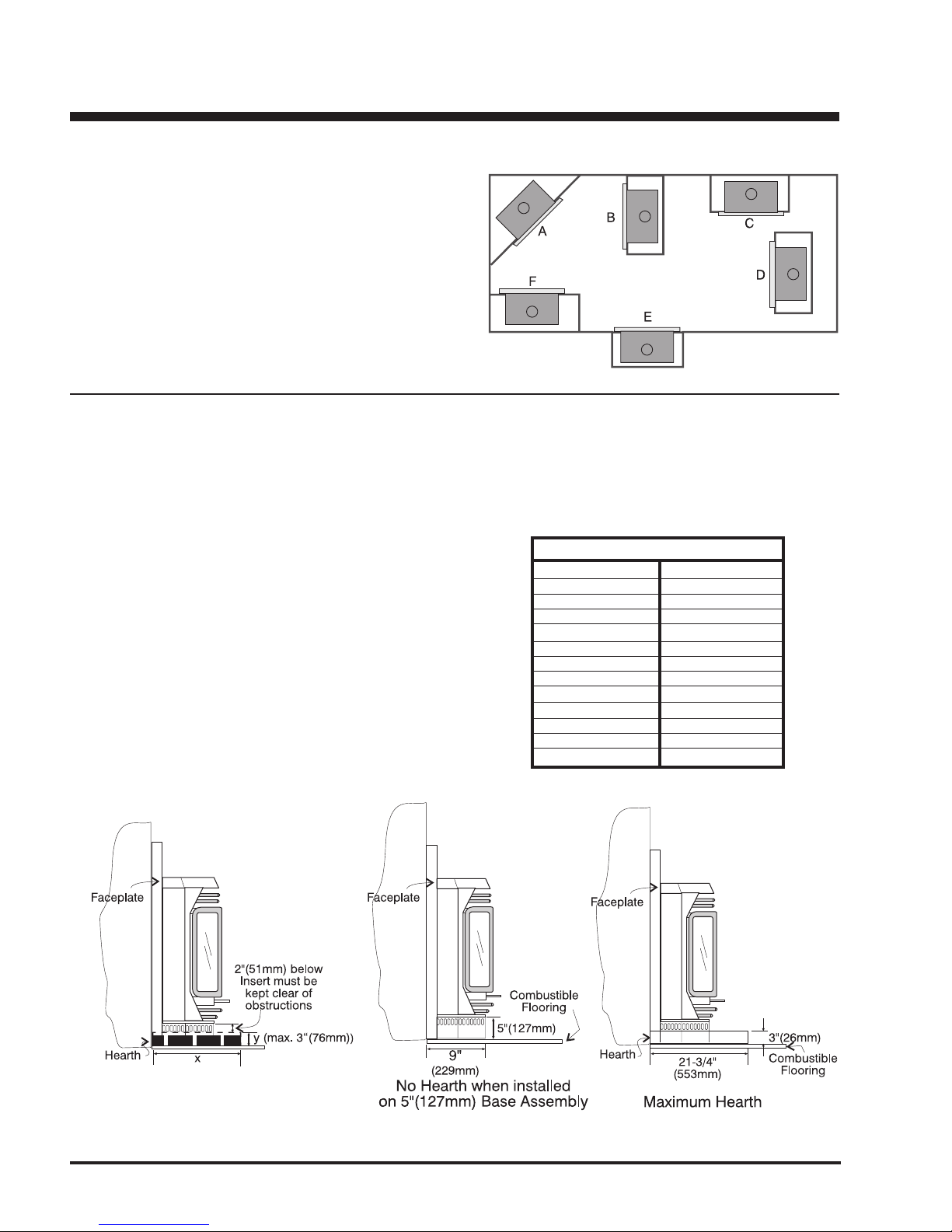
a) Cross Corner d) Island
b) Room Divider e) Flush with Wall
c) Flat on wall f) Flat on Wall Corner
HEARTH
A hearth is not mandatory, but is recommended for aesthetics and for added safety, and if a hearth is installed follow the requirements
listed below. We recommend a non-combustible hearth which comes out a minimum of 12" (305 mm) in front of this appliance. The Zero
Clearance Kit allows for a hearth up to 3" (75 mm) thick above the base to be installed in front of the unit, the ventilation holes must
not be blocked. Note: if the hearth is built up, the faceplates sides will need to be field trimmed to fit, the insulation behind the faceplate
must not be removed.
Non-Combustible Hearth Material
a) non-combustible floor board meeting ASTM E-136 or E-108 or CAN
4-S114 or the equivalent, and offering a thermal resistance (k
factor) of 0.45 or greater.
b) suitable materials include but are not limited to: Wonderboard,
Durock, Micor, Hardibacker, Capeboard, etc.
c) 1"(25mm) thickness of brick.
Non-combustible Hearth
Height (y) Depth (x)
(inches) (mm) (inches) (mm)
3" 76mm 21-3/4" 553mm
2-5/8" 67mm 21" 534mm
2-1/4" 57mm 20" 508mm
1-7/8" 48mm 19" 483mm
1-1/2" 38mm 18" 457mm
1-1/4" 32mm 17" 432mm
1" 26mm 16" 407mm
7/8" 22mm 15" 381mm
5/8" 16mm 13" 330mm
1/4" 7mm 11" 280mm
0" 0m m 9" 229mm
4
U41/I41 Gas Insert Zero Clearance Kit
Page 5
INSTALLATION
FRAMING
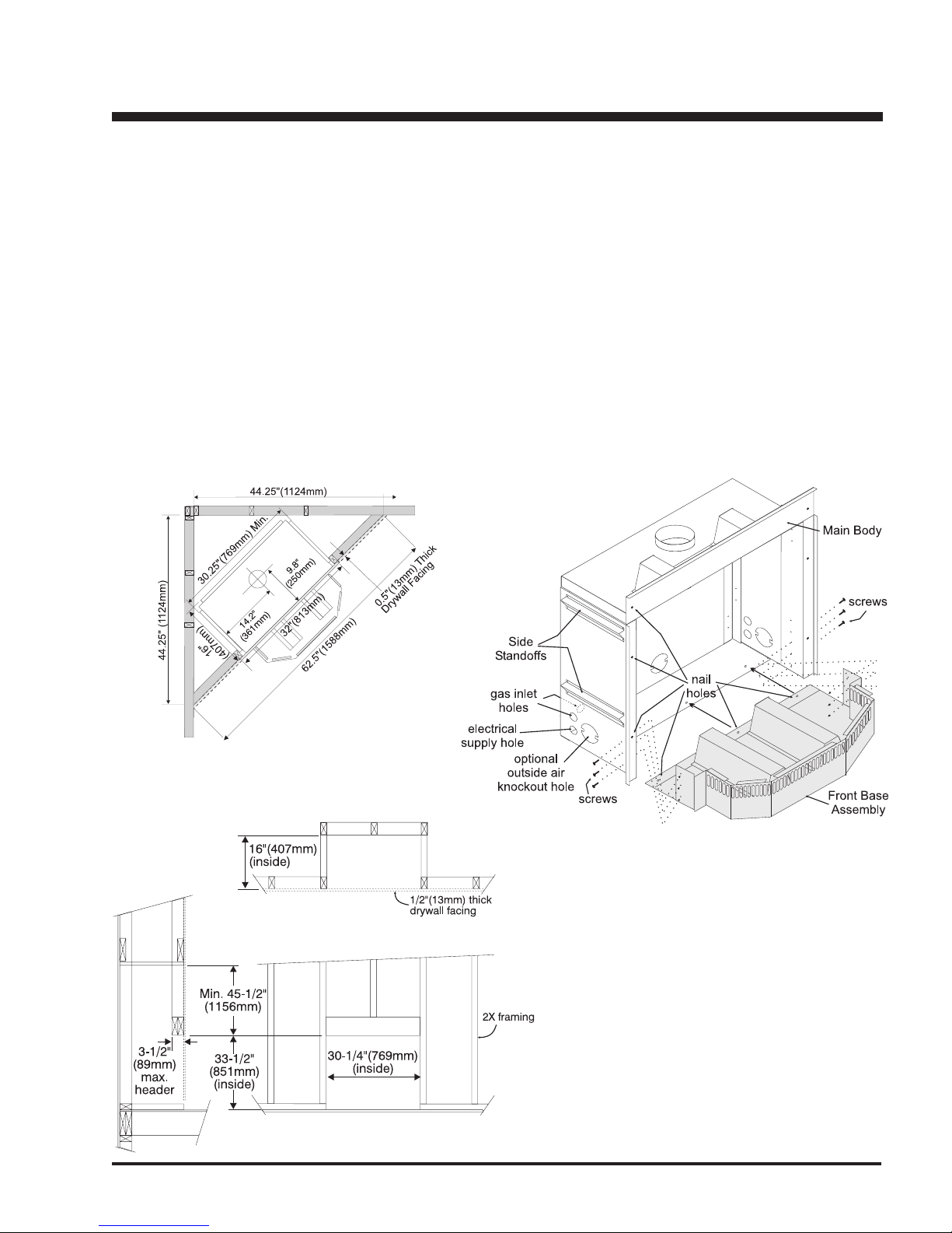
1) The trim kit allows for 1/2" (13 mm) of finish facing material. The
kit may be installed directly on and/or against standard combustible
building materials.
2) Frame in the enclosure for the Kit with framing material. The
framed opening for the assembled kit is 33-1/2" (850 mm) high
x 30-1/4" (769 mm) wide x 16" (407mm) deep. See diagram.
3) For exterior walls vapour barrier and insulate the enclosure to the
same degree as the rest of the house, or according to local
installation codes. In colder climates, if the heater is to be installed
against an exterior wall or chase, insulate the exterior walls
according to local installation codes.
4) Extend the vent chase to a minimum ceiling height of 79" (2007 mm)
at the same width and depth mentioned above. Keep this area
above the unit clear of combustible construction except for the
framing header.
ZERO CLEARANCE KIT ASSEMBLY
Warning: Combustible materials must not extend inside the
stand-offs on the
side, top and rear supports. For safety reasons do not modify
or alter any components of the 660-900 Kit.
1) Slide the Front Base assembly into position on the Main body
assembly as shown in the diagram. Align the screw holes with
the 3 holes on the front side supports. Align the nail holes on the
Front Base assembly base with the base of the Main body
assembly.
2) Use the 3 screws (on each side) to tighten the Main body and Front
Base assembly. Base must be at same elevation as the main body
assembly.
3) Nail the Zero Clearance Kit to the framing, there are 6 predrilled
holes in the front face of the kit (3 per side) and 3 predrilled holes
in the Front Base assembly. It is recommended that the Front Base
assembly and Main body base be nailed to the floor.
U41/I41 Gas Insert Zero Clearance Kit
5
Page 6
INSTALLATION
VENTING
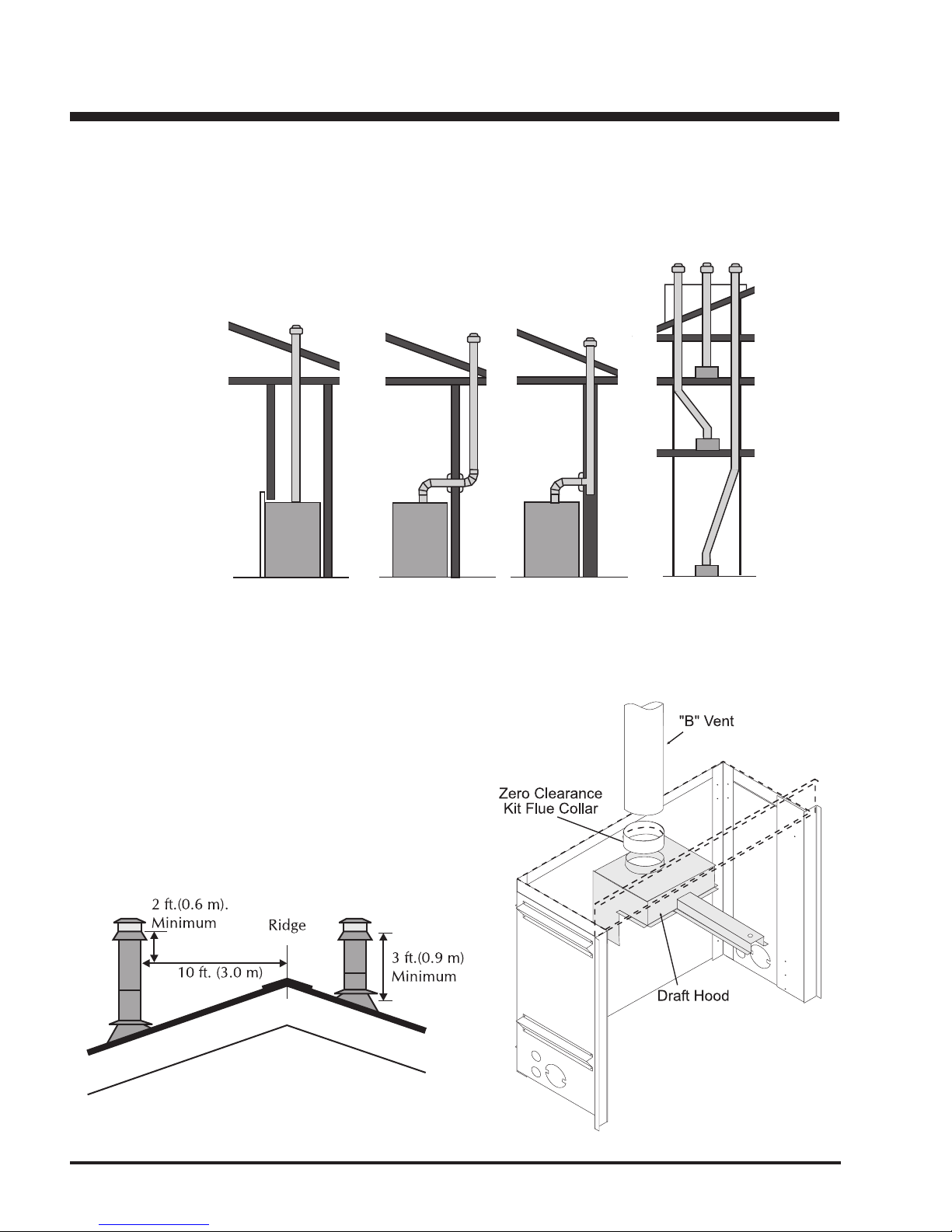
This fireplace must be vented with a 4"(102mm) diameter Class “B” vent (not supplied). The installation of the venting system must conform
and be in accordance with the natural gas installation code CAN/CGA - B149(Canada), ANSI Z223.1 (U.S.A.), AG 601 (Australia), NZS 5261
(New Zealand) and any applicable national or local codes. Minimum chimney height from base of fireplace must be at least 12 feet (3.6 M).
o
Use a maximum of two offsets; four 45
at least 1/4" (6.4 mm) rise per 12" (305mm) of run. Horizontal runs should not exceed the vertical rise.
Keep horizontal runs to a minimum.
elbows, or two 90o elbows for example. Slope horizontal pipe
standard through the wall in the wall multi-storey
Variable Chimney Routes
Flue Vent Termination:
There must be at least 3 ft.(0.9m) of chimney above the roof level. Stack
the pipe onto your finish support to a minimum height of 3 ft.(0.9m) above
the roof penetration, or 2 ft.(0.6 m) above any point within 10 ft. (3 m)
measured horizontally.
In North America, flue systems with vent caps approved by the
Underwriters Laboratories and marked "WIND" may terminate at levels
lower than the 10 ft. - 2 ft. rule. See chimney manufacturer's instructions
for further information.
installation
NOTE: Cold Climate Installation
Do not install against a non-insulated wall or in a chase.
6
U41/I41 Gas Insert Zero Clearance Kit
Page 7
INSTALLATION
OPTIONAL OUTSIDE COMBUSTION AIR SUPPLY INSTALLATION
A 4" (100 mm) dia. aluminum flex pipe or equivalent may be installed from the outside (with a proper exterior cover) to the Zero Clearance
cabinet. There are outside air knock-out holes provided on three sides of the kit. Use only the one that is most suitable for your installation.
This will provide adequate outside combustion air supply to the heater.
GAS SUPPLY LINE
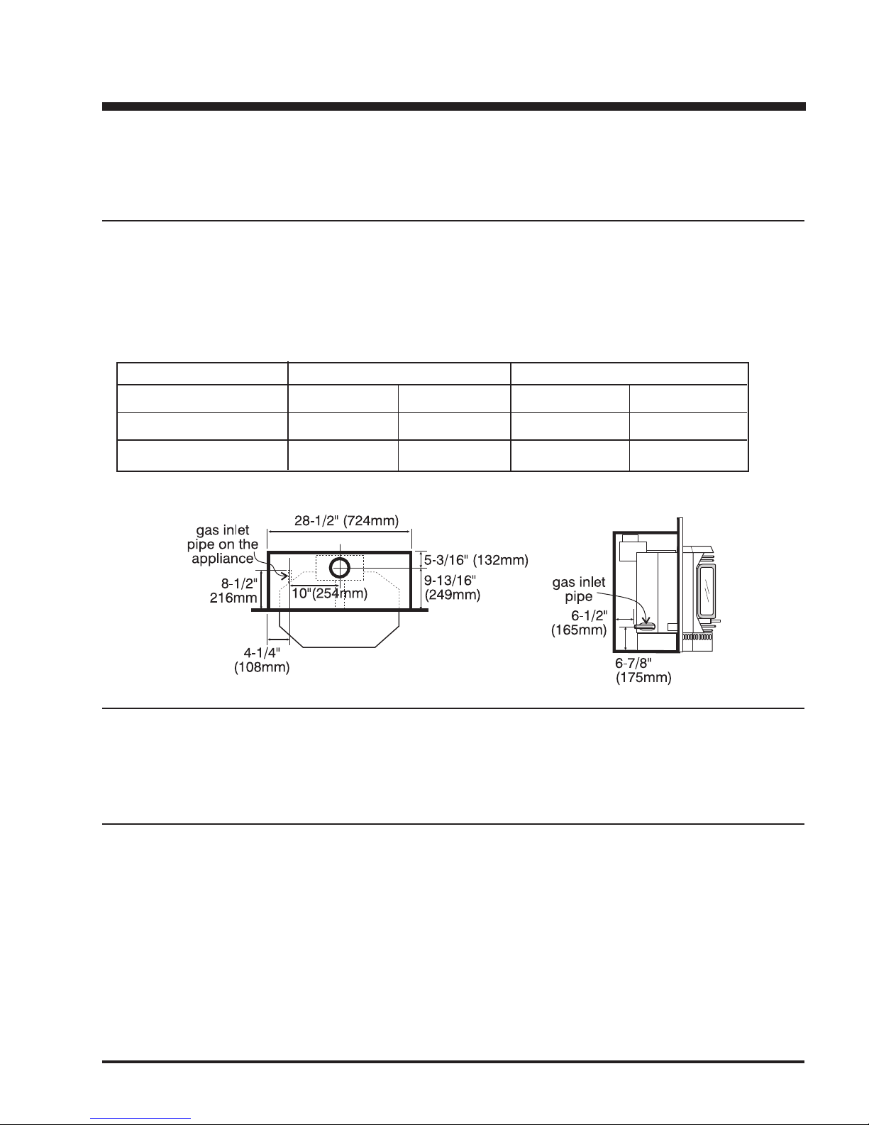
An authorised service person should install the gas line in accordance with all local building codes. If codes permit, flex gas line or coiled copper
tubing may be used as gas supply line. The suggested way to install the gas supply line is as follows: run 1/2" (9.5 mm) NPT gas line to the
left side of the framed opening.
Specifications U41 I41
Natural Gas Propane Natural Gas Propane
Min. Inlet Gas Pressure 5.0" w.c. 11.0" w.c. 1.25 kPa 2.75 kPa
BTU Input Rating 38,000 BTU/hr 38,000 BTU/hr 42,000 BTU/hr 38,000 BTU/hr
Install an electrical outlet box in the lower left rear corner, no higher than 4-1/2" (114 mm) above the bottom and connect 120 VAC (240V in
Australia & New Zealand) to the receptacle. The heater fan power cord will be plugged into this outlet box, or into any receptacle near the
appliance.
Install finished facing surface of 1/2"(13mm) thickness on framing. Drywall 1/2" (13 mm) thick can extend flush with the appliance on all three
sides of the front face. The height at which the mantel must be installed above the top louver depends on the depth of the mantel. If the mantel
is to be painted, use a heat resistant paint to prevent discolouration.
Faceplate and trim installation instructions are in the U41/I41 Insert manual. NOTE: the top faceplate assembly has insulation installed for safety
reasons and must not be removed.
U41/I41 Gas Insert Zero Clearance Kit
WIRING
FINISHED FACING NOTES
7
Page 8

© Copyright 2004, FPI Fireplace Products International Ltd. All rights reserved.
Printed in Canada
 Loading...