

Page 1
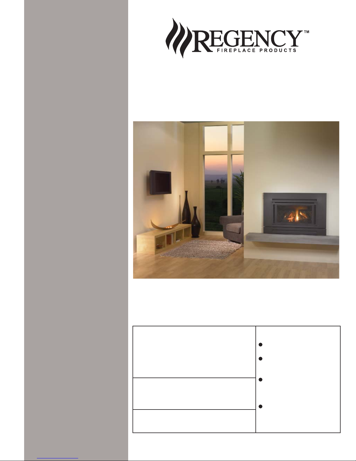
Owners &
Installation
I35 Gas Inbuilt
Models: I35-NG
I35-LPG
I35-ULPG
Manual
LISTINGS AND CODE APPROVALS
These gas appliances have been tested in
accordance with AS4553, NZS 5262 and
have been certifi ed by the Australian Gas
Association for installation and operation as
described in these Installation and Operating
Instructions.
Your unit should be serviced annually by
an authorised service person.
PLEASE KEEP THESE INSTRUCTIONS
FOR FUTURE REFERENCE
WARNING:
Improper installation, adjustment, alteration, service or maintenance can cause
injury or property damage. Refer to this
manual. For assistance or additional information consult an authorised installer,
service agency or the gas supplier.
FOR YOUR SAFETY
Do not store or use gasoline or other fl am-
mable vapours and liquids in the vicinity of
this or any other appliance.
Installation and service must be performed
by an authorised installer, service agency or
the gas supplier.
918-464d
FOR YOUR SAFETY
What to do if you smell gas:
Do not try to light any appli-
ance
Do not touch any electri-
cal switch: do not use any
phone in your building.
Immediately call your gas
supplier from a neighbour's
phone. Follow the gas supplier's instructions.
If you cannot reach your
gas supplier, call the fi re
department.
01/09/16
Page 2
REGENCY
GAS INBUILT FIREPLACE
TO THE NEW OWNER
Congratulations! Y ou are the owner of a state-of-the-art Gas Inbuilt Fireplace by FPI. The Regency
Gas Fireplace Series of appliances has been designed to provide you with all the warmth and
charm of a fi replace, at the fl ick of a switch. The model I35 of this series has been approved by
Australian Gas Association for both safety and effi ciency . As it also bears our own mark, it promises
to provide you with economy, comfort and security for many trouble free years to follow. Please
take a moment now to acquaint yourself with these instructions and the many features of your
Regency Fireplace.
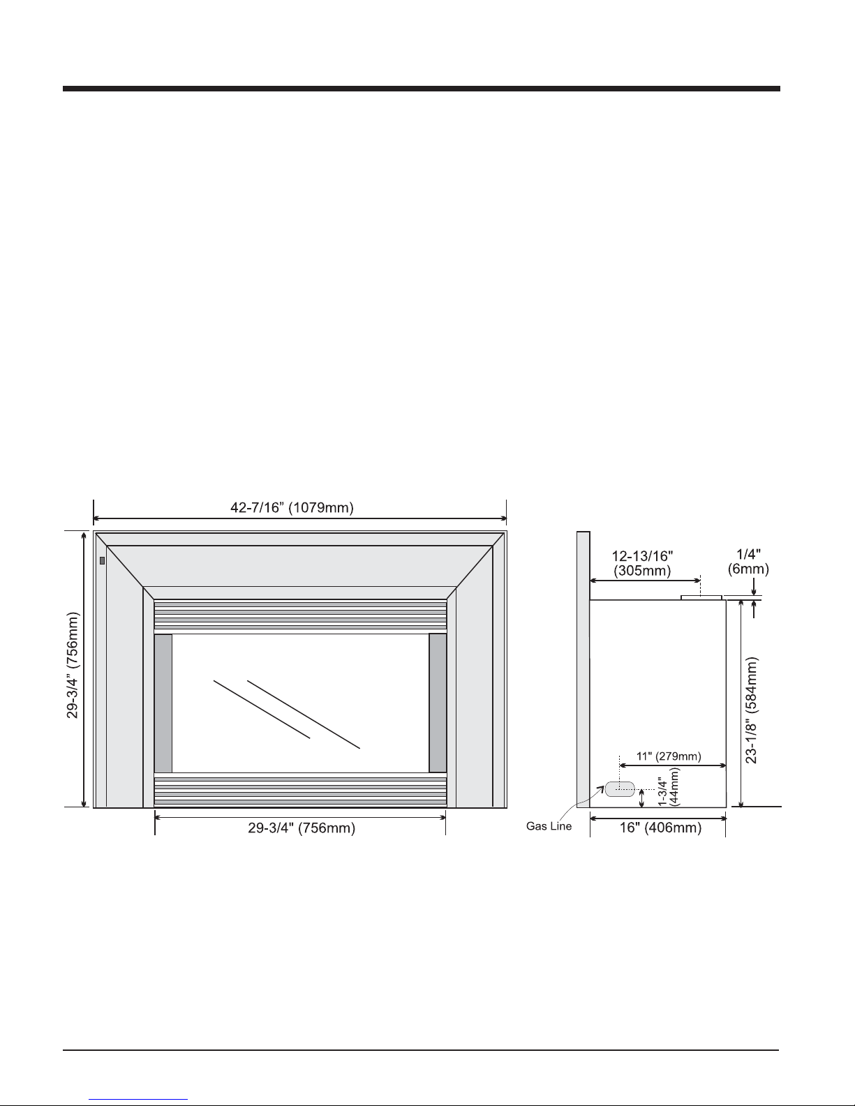
UNIT DIMENSIONS
2
Regency I35 Gas Inbuilt Fireplace
Page 3
TABLE OF CONTENTS
REGENCY GAS FIREPLACE INSERT
DATA BADGE
Data Badge....................................................................5
INSTALLATION
Important Message ........................................................5
For Your Safety ..............................................................5
Before You Start ............................................................5
Installation Checklist ......................................................5
Materials Required ........................................................5
Minimum Fireplace Dimensions ....................................6
Minimum Clearances To Combustibles .........................6
Gas Connection ............................................................6
Flueing ...........................................................................7
Gas Pipe Pressure Testing ............................................7
Test For Flue Spillage ....................................................8
Aeration Settings ...........................................................8
Optional Brick Panel ......................................................8
Conversion Kit #486-968 From NG To LPG ..................9
Conversion Kit #486-967 From NG To ULPG ..............10
Log Set Installation ......................................................11
Faceplate, Trim & Louver Installation ..........................13
Premium Flush Front Installation .................................14
Optional Wall Thermostat ...........................................19
Wiring ..........................................................................19
Final Check..................................................................19
Standard Wiring ...........................................................19
Wiring with Premium Flush Front Option .....................20
OPERATING INSTRUCTIONS
Operating Instructions ................................................21
Shutdown Instructions .................................................21
First Fire ......................................................................21
Automatic Convection Fan Operation..........................21
Lighting Procedure ......................................................21
Adjusting Flame Height ...............................................21
Copy of Lighting Instruction Plate ................................22
Normal Operating Sounds of Gas Appliances .............22
MAINTENANCE
Maintenance Instructions.............................................23
General Flue Maintenance ..........................................23
Log Replacement ........................................................23
Fan Maintenance .........................................................24
Removing Valve Tray ...................................................25
PARTS LIST
Main Assembly ............................................................26
Burner Assembly & Log Set.........................................26
Faceplate Assembly ....................................................27
Premium Flush Front Assembly...................................27
WARRANTY
Warranty ......................................................................31
Regency I35 Gas Inbuilt Fireplace
3
Page 4
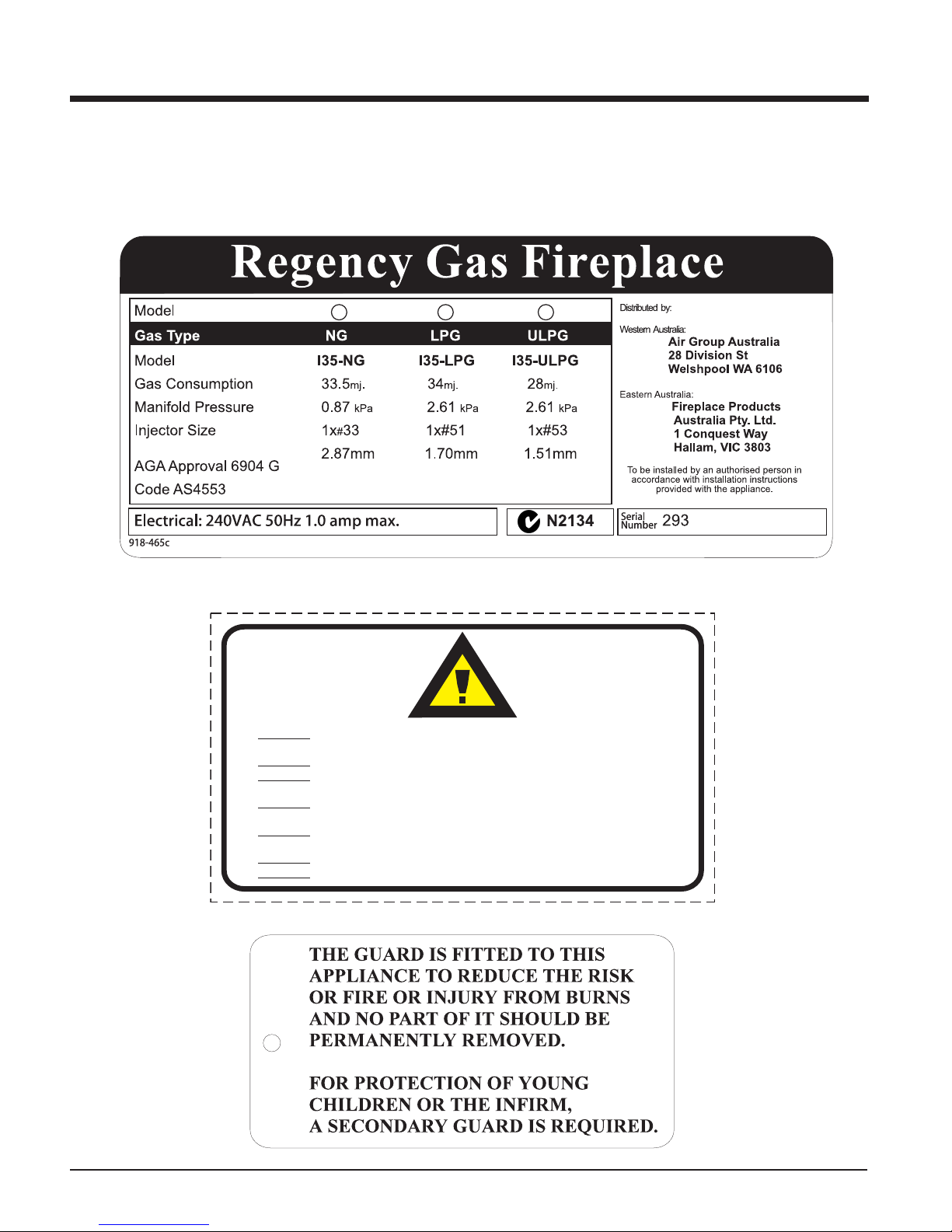
DATA BADGE
This is a copy of the label that accompanies
each Regency I35 Gas Inbuilt fi replace. We
have printed a copy of the contents here for
your review.
DAT A BADGE NOTE: Regency units are constantly being improved. Check the label on the
unit and if there is a difference, the label on the
unit is the correct one.
DO NO T
DO NO T
DO NO T
DO NO T
DO NO T
DO NO T
DO NO T
OPERATE THIS APPLIANCE BEFORE READING THE
INSTRUCTIONS BOOKLET.
PLACE ARTICLES ON OR AGAINST THIS APPLIANCE
STORE CHEMICALS OR FLAMMABLE MATERIALS
NEAR THIS APPLIANCE.
SPRAY AEROSOLS IN THE VICINITY OF THIS
APPLIANCE WHILE IN OPERATION.
OPERATE WITH PANELS, COVERS OR GUARDS
REMOVED FROM THIS APPLIANCE.
ENCLOSE THIS APPLIANCE.
MODIFY THIS APPLIANCE.
908-602a
(Australia Only)
4
Regency I35 Gas Inbuilt Fireplace
Page 5

INSTALLATION
IMPORTANT
MESSAGE
The Regency Gas Fireplace must be installed
in accordance with these instructions. Carefully
read all the instructions in this manual fi rst.
Note: Failure to follow these instructions
could cause a malfunction of the
heater which could result in death,
serious bodily injury, and/or property damage. Failure to follow these
instructions may also void your fi re
insurance and/or warranty.
FOR YOUR SAFETY
This appliance requires air for proper combustion. Always provide adequate combustion and
ventilation air. Follow instructions and information in the current AS5601-2004, NZS 5261
or local codes. Consult the "authority having
jurisdiction" to determine the need for a permit
prior to starting the installation.
MATERIALS REQUIRED
No electric power supply is required for the gas
control to operate. A 240 Volt AC power cord
is hooked up to the unit. Plug 3 wire cord into
a suitable receptacle. Do not cut the ground
terminal off under any circumstances.
When connected with 240 volts, the appliance
must be electrically grounded in accordance
with local codes.
BEFORE YOU ST ART
Installation is to be carried out ONLY by an
authorised person.
1) The appliance shall be installed in accord-
ance with the manufacturer's installation
instructions, local gas fi tting regulations,
municipal building codes, water supply
regulations, electrical wiring regulations,
with AS5601-2004. (AGA gas installation
code) NZS 5261(New Zealand)
2) Installation and repair should be done
ONLY by an authorised person.
3) The appliance should be inspected before
use and at least annually by an authorised
service person. More frequent cleaning may
be required due to excessive lint from carpeting, bedding material, etc. It is imperative
that control compartments, burners and
circulating air passageways of the appliance
be kept clean and free from excessive lint
from carpeting.
4) See general construction and assembly
instructions. This appliance may only be installed in a fl ued, non-combustible fi replace.
The appliance and fl ue should be enclosed
when installed or passing through a living
area, where children may come in contact
with it.
This appliance can also be installed into the
approved Zero Clearance Kit #486-900 in a
combustible situation.
5) Always connect this space heater to a chimney and fl ue to the outside of the building
envelope. Never fl ue to another room. Make
sure that the fl ue is properly sized and is
of adequate height to provide the proper
draft.
6) Inspect the fl ueing system annually for
blockage and any signs of deterioration.
7) Any safety glass removed for servicing
must be replaced prior to operating the appliance.
8) To prevent injury, do not allow anyone who
is unfamiliar with the operation to use the
fi replace.
9) Installer must mechanically attach the supplied label to the inside of the fi rebox of the
fi replace into which the gas fi replace insert
is installed.
INSTALLATION
CHECKLIST
The Regency Gas Insert is installed as listed
below.
1) Unit Location - refer to "Clearances to
Combustibles" section.
2) Make the gas connections. Refer to "Gas
Connections" section.
3) Install the fl ue or liner to the fl ue collar. Refer
to "Flueing" section.
4) Slide the unit into the fi replace.
5) T est gas pressure, refer to "Gas Pipe Pres-
sure T esting" section. Check aeration, refer
to "Aeration Settings" section.
6) Test for fl ue spillage, refer to "Test for Flue
Spillage" section.
7) Install the optional brick panels. Refer to
"Optional Brick Panels" section.
8) Install the log set. Refer to "Log Set installation" section.
9) Assemble and install the faceplate and trim
and louvres. Refer to "Faceplate, Trim &
Louvre" section.
10) Option Premium Flush Front installation.
Refer to "Premium Flush Front Installation"
section.
11) Final check: Before leaving this unit with the
customer, the installer must ensure that the
appliance is fi ring correctly. This includes:
a) Clocking the appliance to ensure the
correct fi ring rate.
b) Adjusting the primary air, if required,
to ensure that the fl ame does not car-
bon.
c) Ensuring that the appliance is fl ueing
correctly. Refer to "T est for Flue Spillage"
section.
Regency I35 Gas Inbuilt Fireplace
"WARNING: This fi replace has been converted
for use with a gas fi replace insert only and
cannot be used for burning wood or solid fuels
unless all original parts have been replaced,
and the fi replace re-approved by the authority
having jurisdiction."
5
Page 6
INSTALLATION
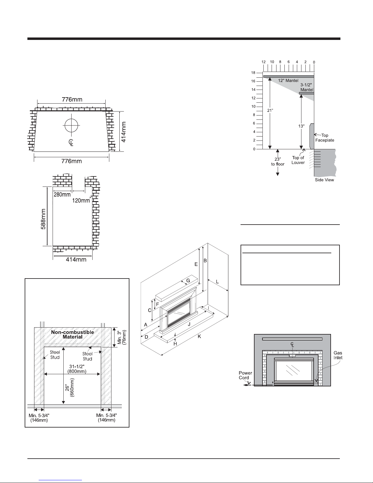
MINIMUM FIREPLACE
DIMENSIONS
The minimum fi replace dimensions for the
Regency gas space heater are shown in the
following diagrams:
MINIMUM
CLEARANCES TO
COMBUSTIBLES
The minimum fi replace clearances for the
Regency gas space heater are shown in the
following diagrams:
From Unit:
Sides A 250 mm
Ceiling B 1220 mm
Mantel C see Mantel
Clearances
From Surround (660 mm x 1016 mm):
Sides D 96 mm
Ceiling E 1066 mm
Max. Mantle Depth G 305 mm
Hearth Height H 0 mm
Hearth Depth I 300 mm*
Hearth Width J 1100 mm
Min. Alcove Width K 1262 mm
Max. Alcove Depth L 915 mm
* NOTE: No hearth required with screen. Floor
fi nishing material must not be any higher then
the base of the fi replace.
Mantel Clearances
Note: A non-combustible mantel may be
installed at a lower height if the framing is made of metal studs covered
with a non-combustible board.
GAS CONNECTION
Premium Flush Front Framing
When installing the Premium Flush Front, the
walls surrounding the zero clearance kit must
be made of non-combustible material. See
Diagram below.
GAS CONNECTION WARNING:
Only persons licensed to work
with gas piping may make the
necessary gas connections to this
appliance.
1) If the appliance is to be installed into an
existing chimney system or Zero Clearance
Box, thoroughly clean the masonry or factory
built fi replace.
2) The gas connection is 1/2" BSP.
3) Locate the center point where the fl ue will
pass through the chimney above the appliance. Move the appliance into the exact
location where it is to be installed. Ensure
that the Insert is level.
6
CAUTION: If the glass is removed for servicing, it must be replaced and closed prior to
operating the appliance.
Regency I35 Gas Inbuilt Fireplace
Page 7
INSTALLATION
FLUEING
THE APPLIANCE MUST NOT BE CONNECTED
TO A CHIMNEY FLUE SERVING A SEP ARA TE
SOLID FUEL BURNING APPLIANCE.
This appliance is designed to attach to a 100
mm diameter twin skin or listed gas fuel type
fl ue liner running the full length of the chimney. A
minimum fl ue height of 1.5 m. is recommended.
The Regency Inbuilt Fireplace incorporates
its own internal draft diverter, so no additional
external draft diverter is required.
Periodically check that the fl ue is unrestricted
and an adequate draft is present when the unit
is in operation.
Before installing fl ue system ensure that the
damper plate is open and secure to prevent the
damper plate from falling down and crushing
the liner.
Install to AS5601-2004,(Australia) NZS 5261
(New Zealand).
Combustion and Ventilation Air
WARNING: This appliance needs
fresh air for safe operation and must
be installed with provisions for adequate combustion and ventilation
air available to the room in which it
is to be operating.
Air for combustion is drawn in through the front
of the unit, therefore, the front of the unit must
be kept clear of any obstructions.
GAS PIPE PRESSURE
TESTING
The appliance must be isolated from the gas
supply piping system by closing its individual
manual shut-off valve during any pressure
testing of the gas supply piping system at
test pressures equal to or less than 1/2 psig.
(3.45 kPa). Disconnect piping from valve at
pressures over 3.45 kPa (14" w.c.).
The manifold pressure is controlled by a regulator built into the gas control, and should be
checked at the pressure test point.
Note: To properly check gas pressure,
both inlet and manifold pressures
should be checked using the valve
pressure ports on the valve.
1) Make sure the valve is in the "OFF" position.
2) Loosen the "IN" and/or "OUT" pressure
tap(s), turning counterclockwise with a
1/8" wide fl at screwdriver.
3) Attach manometer to "IN" and/or "OUT"
pressure tap(s) using a 5/16" ID hose.
4) Light the pilot and turn the valve to "ON"
position. Read manometer.
5) The pressure check should be carried out
with the unit burning and the setting should
be within the limits specifi ed on the safety
label.
6) When fi nished reading manometer, turn
off the gas valve, disconnect the hose and
tighten the screw (clockwise) with a 1/8"
fl at screwdriver. Note: Screw should be
snug, but do not over tighten.
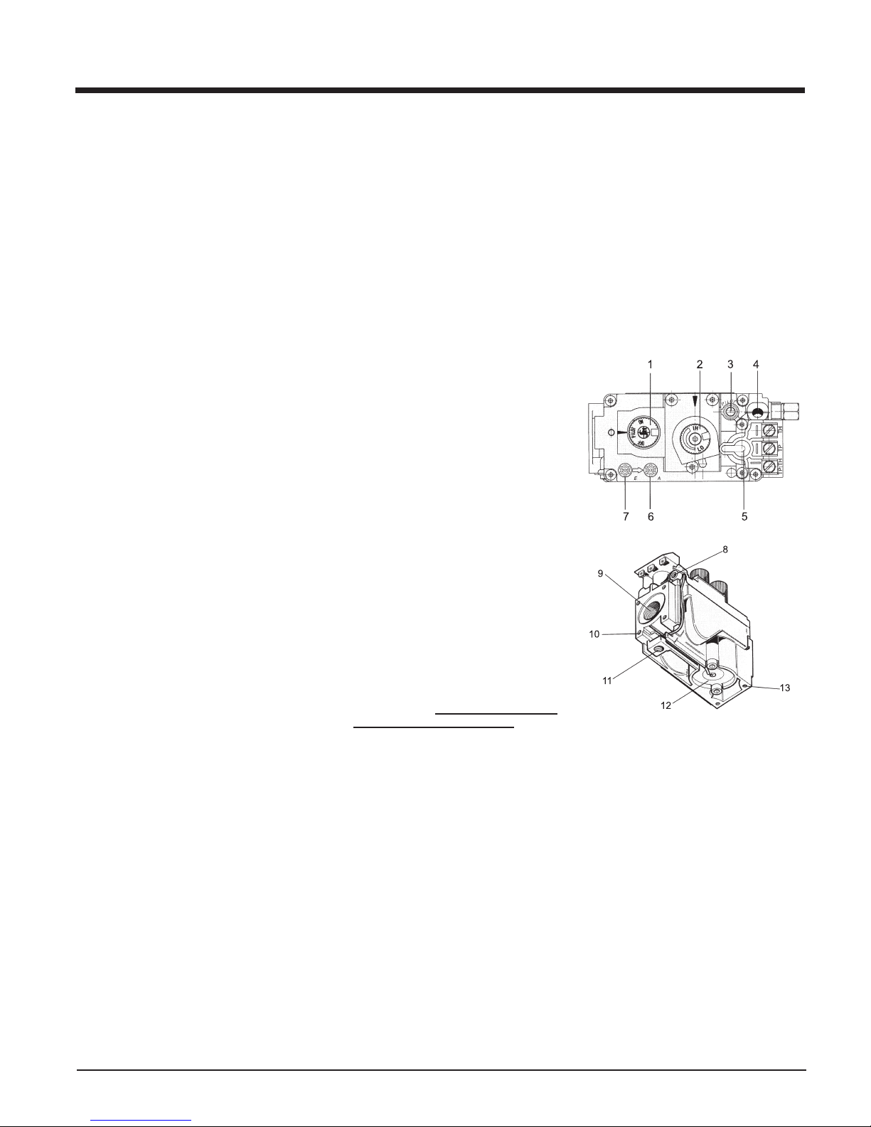
Valve Description
1) Gas on/off knob
2) Manual high/low adjustment
3) Pilot Adjustment
4) Thermocouple Connection
5) Main Operator
6) Outlet Pressure Tap (Manifold Pressure)
7) Inlet Pressure Tap (Supply Pressure)
8) Pilot Outlet
9) Main Gas Outlet
10) Flange Securing Screw Holes
11) Alternative TC Connection Point
12) Thermoelectric Unit
13) Additional Valve Mounting Hole
Regency I35 Gas Inbuilt Fireplace
7
Page 8
g
INSTALLATION
System Data
I35
I35-NG: For 0 to 610 meters altitude
I35-LPG: For 0 to 610 meters altitude
I35-ULPG: For 0 to 610 meters altitude
Burner Inlet Orifi ce Sizes:
NG LPG ULPG
Burner #33 #51 #53
Max. Input
NG 33.5 mj
LPG 34 mj
ULPG 28 mj
Min. Input
NG 19.6 mj
LPG 18.5 mj
ULPG 14 mj
Supply Pressure
NG 1.13 kPa
LPG 2.75 kPa
ULPG 2.75 kPa
Manifold Pressure
NG 0.87 kPa
LPG 2.61 kPa
ULPG 2.61 kPa
Electrical: 240 V. 50Hz.
Circulation: High/Off/LO speed fan,
150/89 CFM.
Log Set: Ceramic fi ber, 7 per set.
TEST FOR FLUE
SPILLAGE
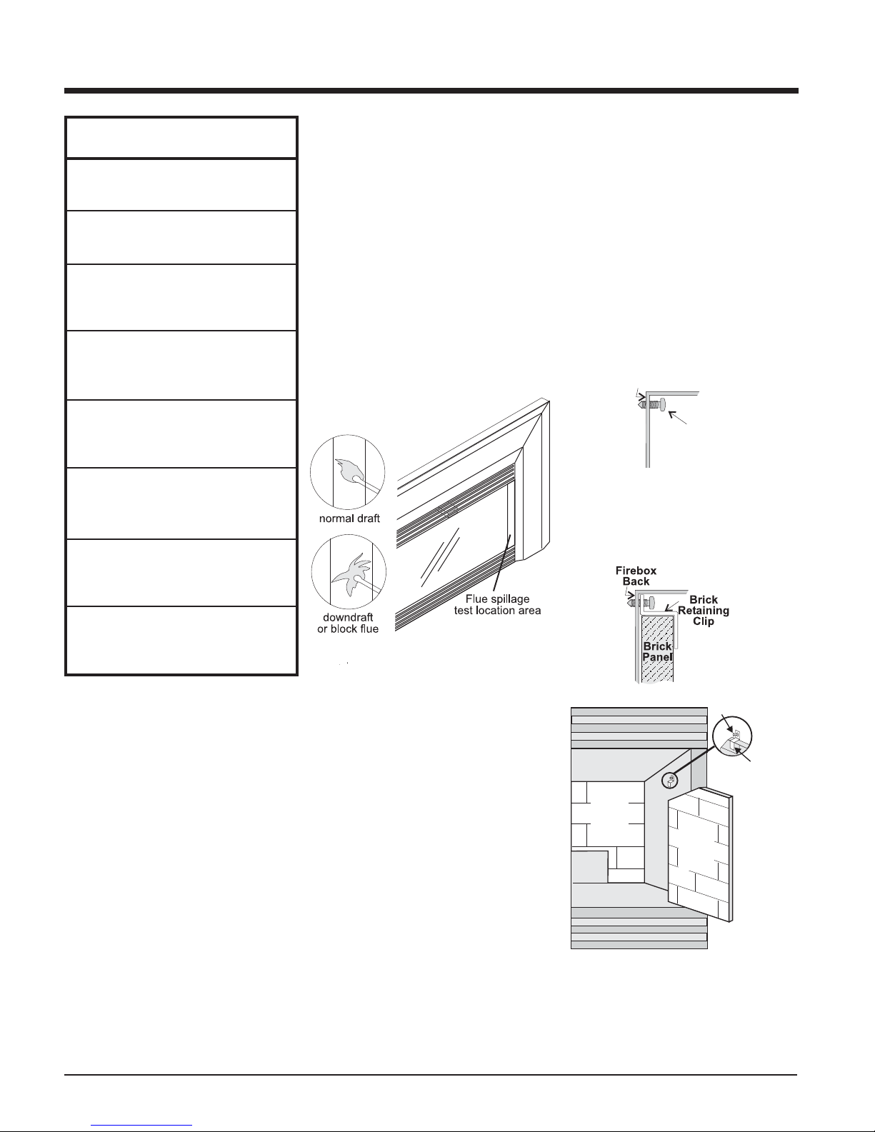
A " spillage" test must be made before the
installed unit is left with the customer. Follow
the procedure below:
1) Start all exhaust fans in the home and then
close all external doors and windows in the
house.
2) Light the unit and set controls to maximum.
Turn fan off.
3) After fi ve minutes, test that there is a “pull” on
the fl ue by placing a smoke match, cigarette
or similar device which gives off smoke, in
both sides of the unit. See diagram 1.
OPTIONAL
BRICK PANEL
1) Unwrap the brick panels from the protective
wrapping.
2) Remove the glass front and log set if already
installed.
3) Place the rear brick panel fl at against the
back of the unit, by carefully slipping it between the back wall of the fi rebox and the
rear log tray.
4) Remove the screw on the inside top left and
right side of the fi rebox.
Left Side
of Firebox
Rem ove
screw
5) Slide the left and right side brick panels in
place and secure using the brick retaining
clips provided and the screws removed in
step 4 as shown in the diagram below.
Aeration Setting
NG 15mm fully open
LPG 15mm fully open
ULPG 15mm fully open
AERATION SETTINGS
The burner aeration is factory set but may need
adjusting due to either the local gas supply, air
supply or altitude. This adjustment is performed
by the installer. (Close the aeration for a more
yellow fl ame, or open it to make the fl ame
bluer).
NG: 15mm fully open
LPG: 15mm fully open
ULPG: 15mm fully open
Note: Any damage due to carboning result-
ing from improperly setting the aeration controls is NOT covered under
warranty.
Diagram 1
The smoke should be drawn into the unit. If the
smoke is still not drawn into the spill tube, turn
the unit off and check for the cause of the lack
of draft. If necessary, rectify.
For wind turbulent sites, a wind cap may remedy the problem. These caps are not included
with the standard fl ue kit and will need to be
purchased separately.
Back
brick
panel
Screw
Brick
Retainin
Clip
Side
brick
panel
8
Regency I35 Gas Inbuilt Fireplace
Page 9
INSTALLATION
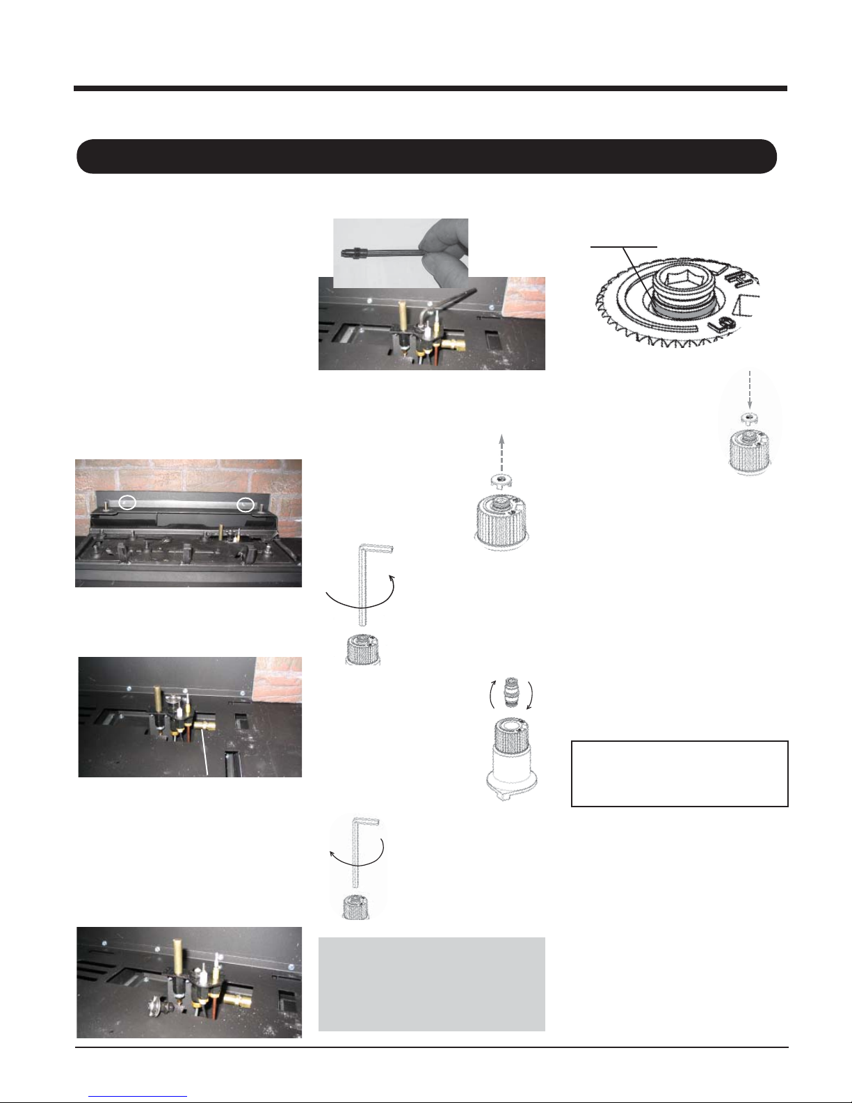
CONVERSION KIT #486-968 FROM NG TO LPG
THIS CONVERSION MUST BE DONE BY A QUALIFIED GAS FITTER IF IN DOUBT DO NOT DO THIS CONVERSION !!
Conversion Kit #486-968 Contains:
Qty. Part # Description
1 910-037 LPG Injector (Pilot Orifi ce)
1 904-645 Burner Orifi ce #51
1 908-528 Red "LPG" label
1 918-590 Label "Converted to LPG"
1 904-529 Allen Key 5/32
1 918-541 Instruction Sheet
1) Shut off the gas supply and unplug the
power cord.
2) Remove the front door.
3) Remove logs.
4) Remove the rear log tray by removing the 2
screws. (Log tray must be rotated to clear
the burner.)
10) Unscrew the pilot orifi ce with the allen key
and replace with the LPG pilot orifi ce in the
kit.
11) Replace pilot cap.
12) Turn control knob to the "OFF" position.
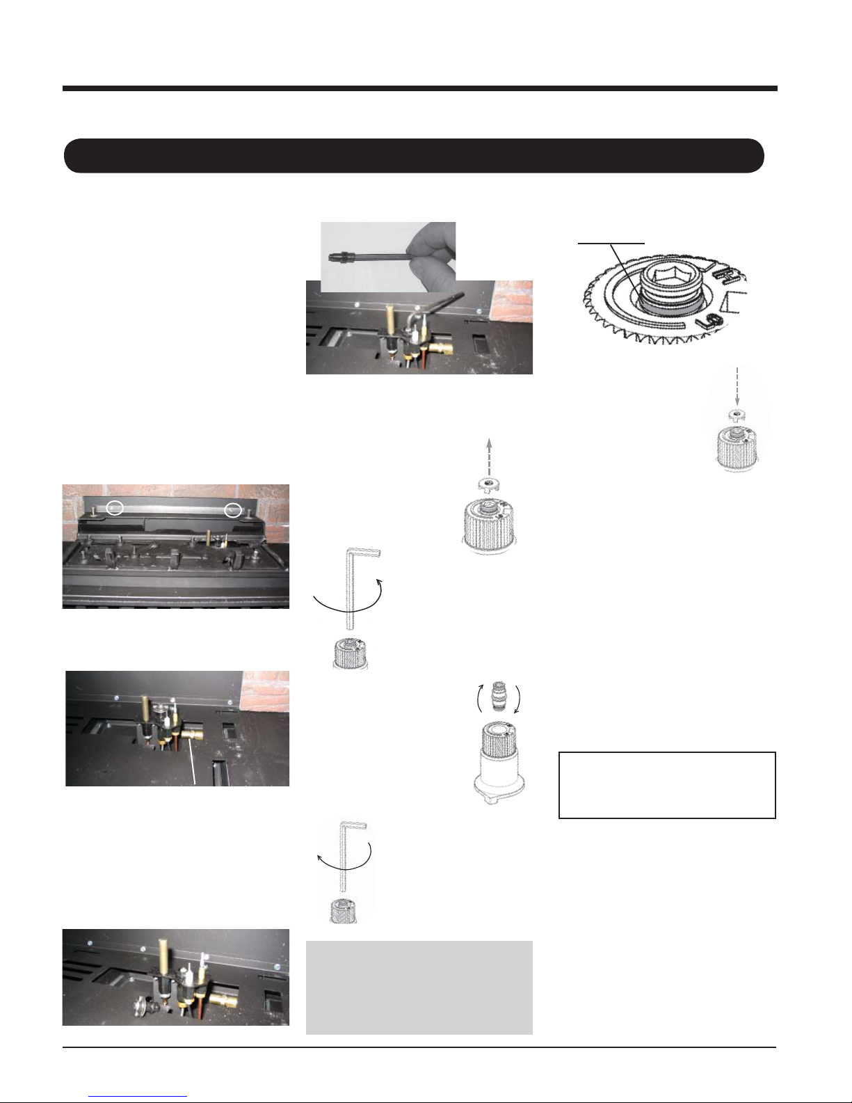
13) Remove the black
protection cap by hand
from the hi-low knob
(Fig. 1).
Fig. 1
18) Verify that if the conversion is from NG to
LPG, the screw must be re-assembled with
the red o-ring visible (Fig. 5).
Red o-ring visible
LPG Configuration
Fig.5
19) Re-assemble the black
protection cap (Fig. 6).
Fig. 6
20) Attach the Conversion label "This unit has
been converted to LPG" on top of the data
badge.
21) Replace yellow "NG" label with red "LPG"
label.
5) Remove the grate.
6) Remove the burner and adjust the aeration
setting to 15mm fully open.
Burner Orifi ce
7) Remove burner orifi ce with a 1/2" spanner
and discard. Use a spanner to hold on to
the elbow behind the orifi ce.
8) Reinstall new burner orifi ce LPG stamped
#51 and tighten.
9) Pull off the pilot cap to expose the pilot
orifi ce.
14) Insert a 5/32" or 4mm
Allen wrench into the
hexagonal key-way of
the screw (Fig. 2), rotate
it counterclockwise until it
is free and extract it.
Fig.2
15) Check that the screw is
clean and if necessary
remove dirt.
16) Flip the srew (Fig. 3).
Fig.3
17) Using the Allen wrench as
shown in Fig. 4, rotate the
screw clockwise until snug,
do not overtighten.
Fig.4
WARNING!
Do not over tighten the screw.
Recommended to grip the
wrench by the short side.
22) Reverse steps 6 to 1.
23) Check for gas leaks.
24) Check inlet and outlet pressures.
25) Check operation of fl ame control.
26) Check for proper fl ame appearance and
glow on logs.
Installer Notice:
These instructions must be left
with the appliance.
Regency I35 Gas Inbuilt Fireplace
9
Page 10
INSTALLATION
CONVERSION KIT #486-967 FROM NG TO ULPG
THIS CONVERSION MUST BE DONE BY A QUALIFIED GAS FITTER IF IN DOUBT DO NOT DO THIS CONVERSION !!
Conversion Kit #486-967 Contains:
Qty. Part # Description
1 910-037 LPG Injector (Pilot Orifi ce)
1 904-345 Burner Orifi ce #53
1 918-273 Red "ULPG" label
1 918-272 Label "Converted to ULPG"
1 904-529 Allen Key 5/32
1 918-542 Instruction Sheet
1) Shut off the gas supply and unplug the power
cord.
2) Remove the front door.
3) Remove logs.
4) Remove the rear log tray by removing the 2
screws. (Log tray must be rotated to clear
the burner.)
5) Remove the grate.
6) Remove the burner and adjust the aeration
setting to 15mm fully open.
Burner Orifi ce
7) Remove burner orifi ce with a 1/2" spanner
and discard. Use a spanner to hold on to
the elbow behind the orifi ce.
8) Reinstall new burner orifi ce ULPG stamped
#53 and tighten.
9) Pull off the pilot cap to expose the pilot
orifi ce.
10) Unscrew the pilot orifi ce with the allen key
and replace with the ULPG pilot orifi ce in
the kit.
11) Replace pilot cap.
12) Turn control knob to the "OFF" position.
13) Remove the black
protection cap by hand
from the hi-low knob
(Fig. 1).
Fig. 1
14) Insert a 5/32" or 4mm
Allen wrench into the
hexagonal key-way of
the screw (Fig. 2), rotate
it counterclockwise until it
is free and extract it.
Fig.2
15) Check that the screw is
clean and if necessary
remove dirt.
16) Flip the srew (Fig. 3).
Fig.3
17) Using the Allen wrench as
shown in Fig. 4, rotate the
screw clockwise until snug,
do not overtighten.
Fig.4
18) Verify that if the conversion is from NG to
ULPG, the screw must be re-assembled
with the red o-ring visible (Fig. 5).
LPG Configuration
Red o-ring visible
U
Fig.5
19) Re-assemble the black
protection cap (Fig. 6).
Fig. 6
20) Attach the Conversion label "This unit has
been converted to ULPG" on top of the
data badge.
21) Replace yellow "NG" label with red "ULPG"
label.
22) Reverse steps 6 to 1.
23) Check for gas leaks.
24) Check inlet and outlet pressures.
25) Check operation of fl ame control.
26) Check for proper fl ame appearance and
glow on logs.
Installer Notice:
These instructions must be left
with the appliance.
10
WARNING!
Do not over tighten the screw.
Recommended to grip the
wrench by the short side.
Regency I35 Gas Inbuilt Fireplace
Page 11
INSTALLATION
LOG SET
INSTALLATION
Read the instructions below carefully and
refer to the diagrams. If logs are broken
do not use the unit until they are replaced.
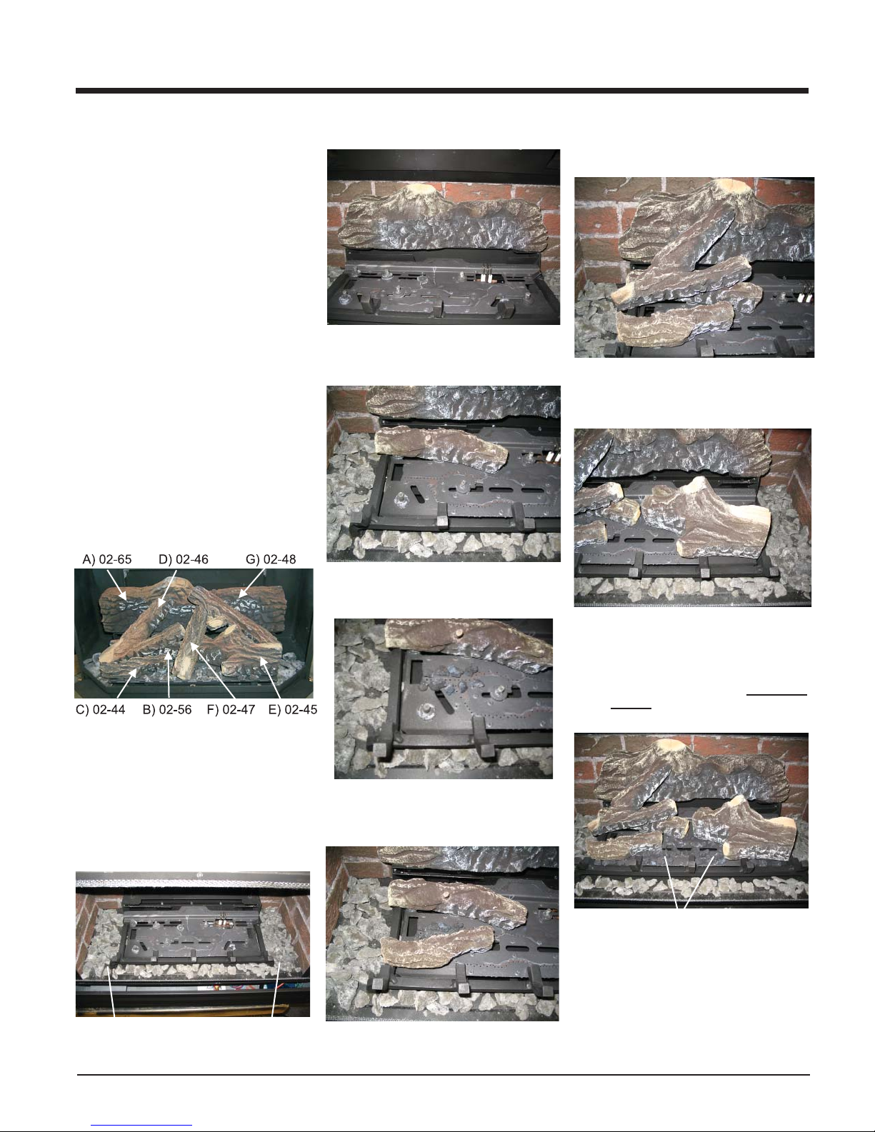
Log kit #730-935 contains the following:
a) 02-65 Rear Log
b) 02-56 Middle Left Log
c) 02-44 Front Left Log
d) 02-46 Left Top Log
e) 02-45 Front Right Log
f) 02-47 Center Log
g) 02-48 Middle Right Log
h) Embers 902-151
i) Lava 902-154
Log kit #486-930 contains the following:
a) 02-50 Side Log
b) 02-52 Side Log
c) Embers 902-151
d) Lava 902-154
The "02" refer numbers (i.e. 02-65) are
molded into the rear of each log.
3) Place Rear Log A)02-65 on the two pins on
the rear log support.
A)02-65
4) Place the Middle Left Log B)02-56 on the
two pins from the rear left side.
B)02-56
7) Place the Left Top Log D)02-46 on the pin
on Log B)02-56 and on top of the cutout
on Log A)02-65.
A)02-65
D)02-46
C)02-44
8) Place Front Right Log E)02-45 on the two
pins as shown.
B)02-56
E)02-45
Installation of Kit 730-935:
1) Carefully remove the logs from the box and
unwrap them. The logs are fragile, handle
with care - do not force into position.
2) Sprinkle the embers on the front, left and
right sides of the fi rebox base.
5) Place lava rock in front of middle left log as
shown in the picture.
9) Place the lava rock in the area between
the left and right logs, leaving a space in
the middle for log (F) 02-47.
Ensure that the lava rocks are not placed
directly over the burner ports.
6) Place Front Left Log C)02-44 onto the 2
front pins as shown.
Lava Rock
C)02-44
Embers
Regency I35 Gas Inbuilt Fireplace
Embers
11
Page 12
INSTALLATION
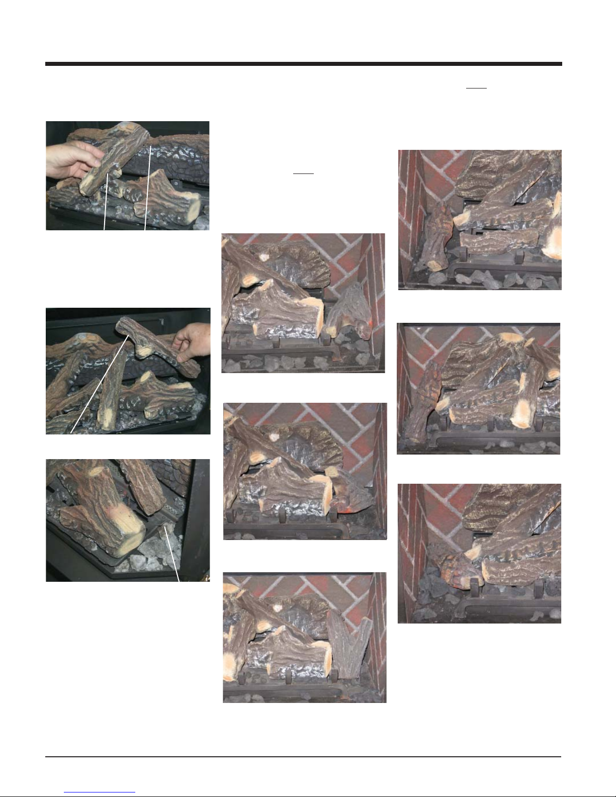
10) Place the notch in Center Log F)02-47 over
Log E)02-45 and across the cutout on Log
A)02-65.
F)02-47
CutoutNotch
11) Position notch in Front Right Log G)02-48
on Log F)02-47 and push the bottom right
edge against the bracket on the burner
tray.
A)02-65
G)02-48
A)02-65
E)02-45
Installation of Kit 486-930:
1) Carefully remove the logs from the box and
unwrap them. The logs are fragile, handle
with care - do not force into position.
2) Sprinkle the embers on the front, left and
right sides of the fi rebox base.
3) Place Side Log 02-50 on the right side of
the grate on the fi rebox base.
Position log as desired ensuring the log
DOES NOT interfere with the fl ame. Possible
positioning shown in diagrams below.
02-50
4) Place Side Log 02-52 on the left side of the
grate on the fi rebox base.
Position log as desired ensuring the log
DOES NOT interfere with fl ame. Possible
positioning shown in diagrams below.
02-52
Example 1
E)02-45
F)02-47
Notch
G)02-48
E)02-45
Side View
Bracket
The bottom right edge of Log G)02-48 must
sit snugly against the bracket
12) T est fi re to ensure proper light off. Ensure
fl ame fl ows smoothly from one end of the
burner to the other. If there is any fl ame
hesitation, check the area for any blockage
of the burner port.
Example 1
Example 2
Example 3
02-52
Example 2
02-50
02-52
Example 3
02-50
5) Test fi re to ensure proper light off. Ensure
fl ame fl ows smoothly from one end of the
burner to the other. If there is any fl ame
hesitation, check the area for any blockage
of the burner port.
12
Regency I35 Gas Inbuilt Fireplace
Page 13
INSTALLATION
FACEPLATE,
TRIM & LOUVER
INSTALLATION
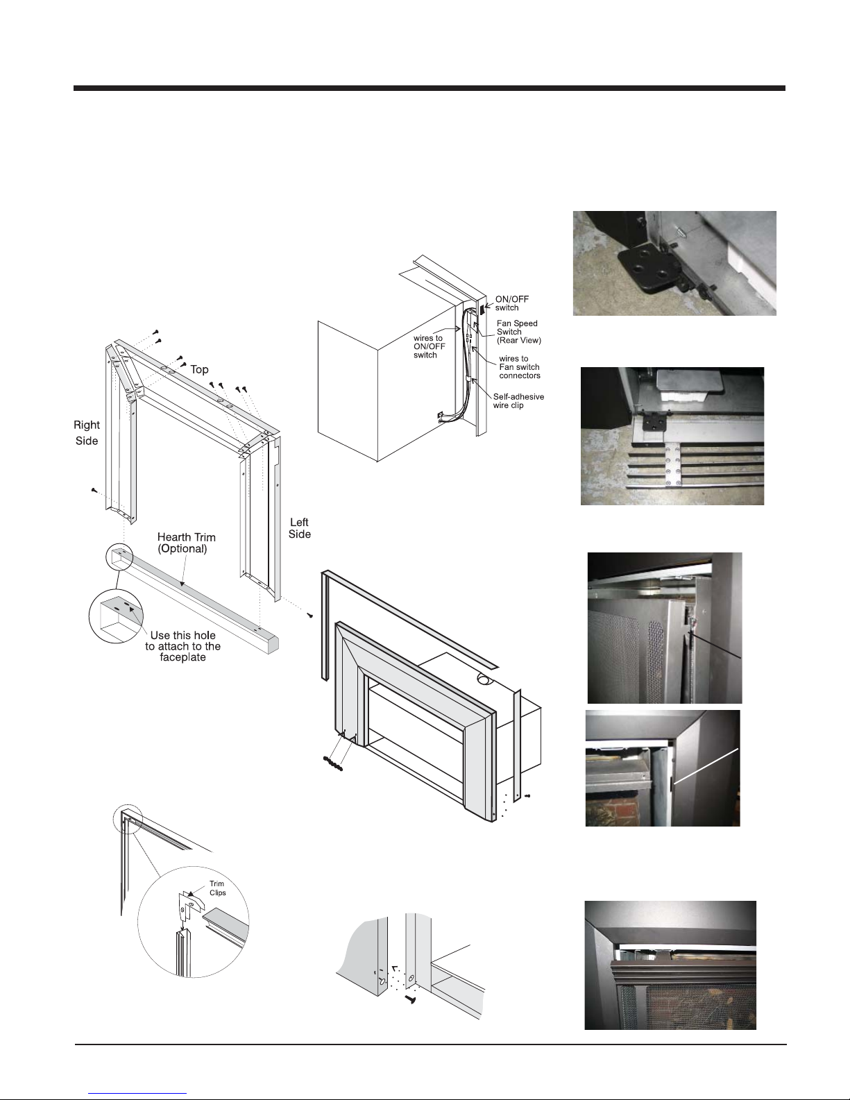
1) Lay the faceplate panels fl at, face down on
something soft so they don't scratch.
2) Take the top faceplate and align the holes
in it with the holes in the side panels. Using the screws provided, attach from the
top of the panel (the holes in the top panel
are slightly larger than the holes in the side
panel to facilitate easier installation).
4) Connect the fan harness to the fan switch.
5) Connect the valve harness to the valve on/off
switch.
6) Tuck the wires into the faceplate to keep
them away from the inbuilt fi replace using
the clip provided. Attach the clip to the rear
of the faceplate to ensure that the wires do
not touch the side of the unit.
7) The power cord should be run behind the
faceplate panel.
10) Push the Regency logo plate into the two
holes in the bottom left corner of the faceplate.
11) Place the 2 hinges for the bottom louver
in position and secure using 4 screws per
hinge.
12) Place the bottom louver in position and
secure it with 6 screws.
Diagram 1
Hint: Don't tighten the trim to the bottom
of the faceplate side panels with the screws
provided. See diagram 1.
3) Using the connectors provided, join the left
side trim to the top trim. Connect the right
side trim to the top trim.
8) Place the trim on the assembled faceplate
panels and secure it with the side screws.
9) Attach the faceplate panels* to the inbuilt
fi replace body using 4 black screws.
13) Install the safety screen by inserting the 4
screen brackets into the 4 slots.
Screen
Bracket
Slots
14) Install the top louver by sliding the 2 bracket
clips into the brackets located on top of the
unit.
Diagram 2
Rear View: Trim Assembly
Regency I35 Gas Inbuilt Fireplace
Side
Screws
13
Page 14
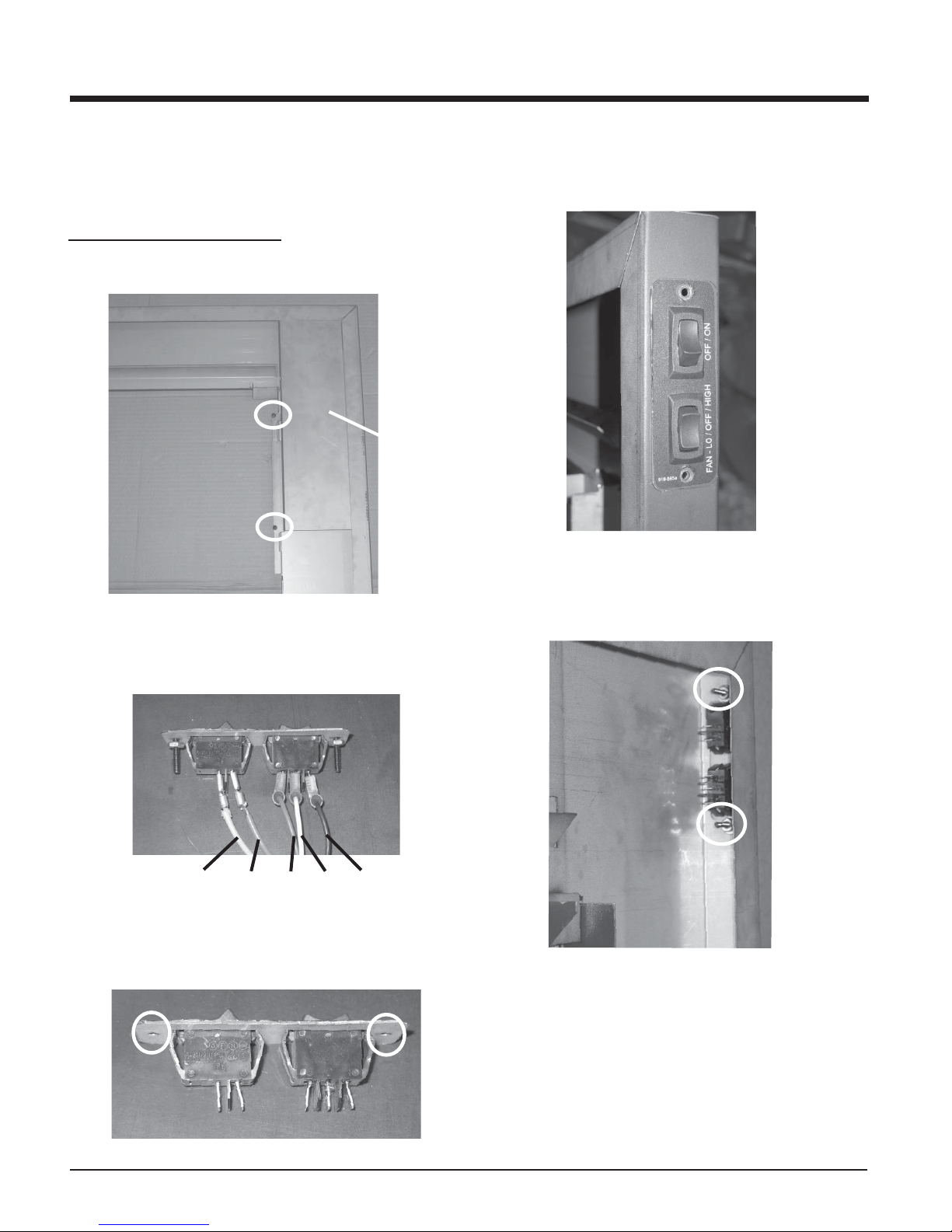
INSTALLATION
PREMIUM FLUSH FRONT INSTALLATION
1) Unplug the power source.
2) Remove the glass door.
ON/OFF & Fan Switch Installation:
3) Remove the heat shield from the left side of the faceplate by undoing
the 2 screws. See diagram 1.
Left Side
Heat Shield
Diagram 1
6) Place the manual control switch into the opening on the left side of
the faceplate as shown in diagram 4.
Diagram 4
7) Secure the manual control switch in place using the 2 bolts and nuts
removed in step 5. See diagram 5.
4) Disconnect the wires connected to the On/Off and Fan switch. See
diagram 2.
ON/OFF FAN
Yellow
5) Remove the 2 bolts and nuts from the On/Off & Fan switch. See
diagram 3.
Orange
Red White Black
Diagram 2
Diagram 5
Diagram 3
14
Regency I35 Gas Inbuilt Fireplace
Page 15
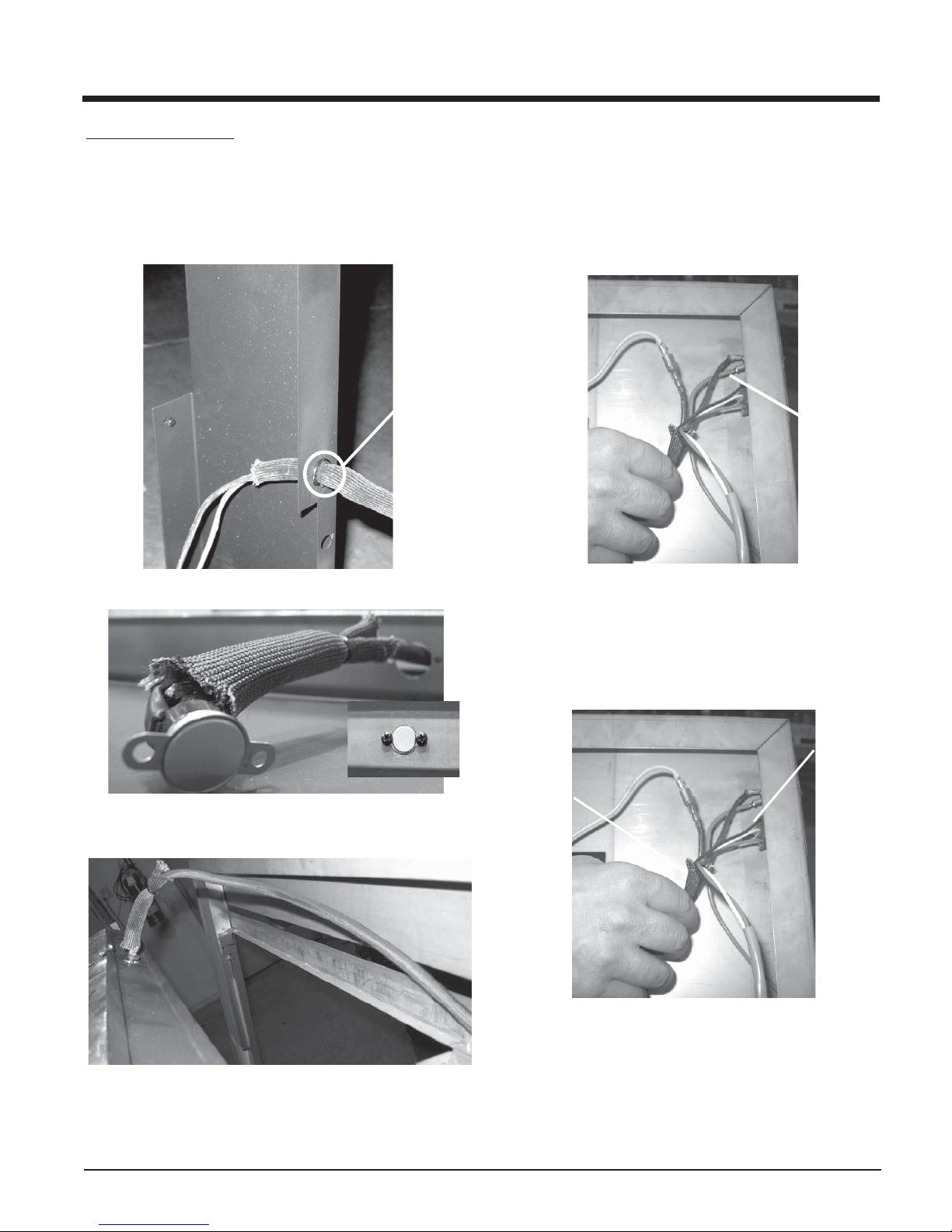
INSTALLATION
Thermodisc Installation:
8) Run the thermodisc wires thru the hole in the heat shield.
Then place the grommet over the sleeve and tuck into the hole in
the heat shield as shown in diagram 6.
Grommet
Diagram 6
11) Reconnect the red, white and black fan wires to the fan switch on
the faceplate. Refer to diagram 2 for sequence of attachment.
12) Reconnect the orange wire to the bottom terminal on the On/Off
switch. See diagram 9.
Orange
Wire
Diagram 9
Diagram 7
9) Secure with 2 Phillips Head Screws as shown.
See Diagram 7 inset
Diagram 8
10) Bring faceplate close to unit.
13) Connect the female wire connector from the thermodisc wires (included
with kit) to the top terminal of the On/Off switch. See diagram 10.
Female
Connector
Thermodisc
Wires
Faceplate
Diagram 10
11) Run thermodisc wires from top of heat defl ector through
left side of faceplate. See Diagram 8
Regency I35 Gas Inbuilt Fireplace
15
Page 16
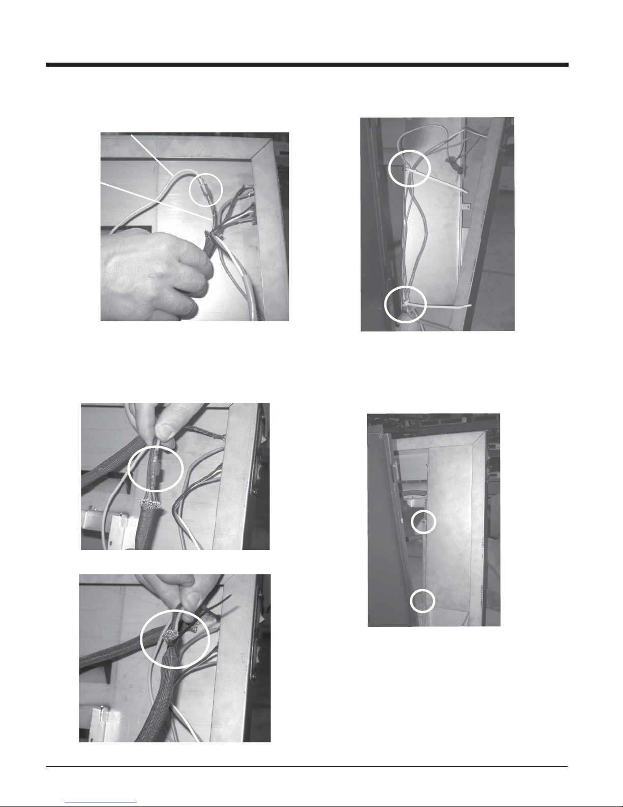
INSTALLATION
14) Connect the yellow wire originally connected to the On/Off switch to
the male wire on the thermodisc wires (included with kit). See diagram
11.
Yellow Wire
Male
Thermodisc
Wire
Diagram 11
15) Tuck the yellow wire into the thermodisc sleeve, see diagram 12. Cable
tie the top of the sleeve to ensure connector is secure in sleeve. See
Diagram 13.
16) Place the cable ties thru the cable tie holders in the heat shield to
secure loose wires. See diagram 14.
Diagram 14
17) Secure the heat shield to the faceplate using 2 screws. See diagram
15.
Diagram 12
Diagram 13
16
Diagram 15
Regency I35 Gas Inbuilt Fireplace
Page 17
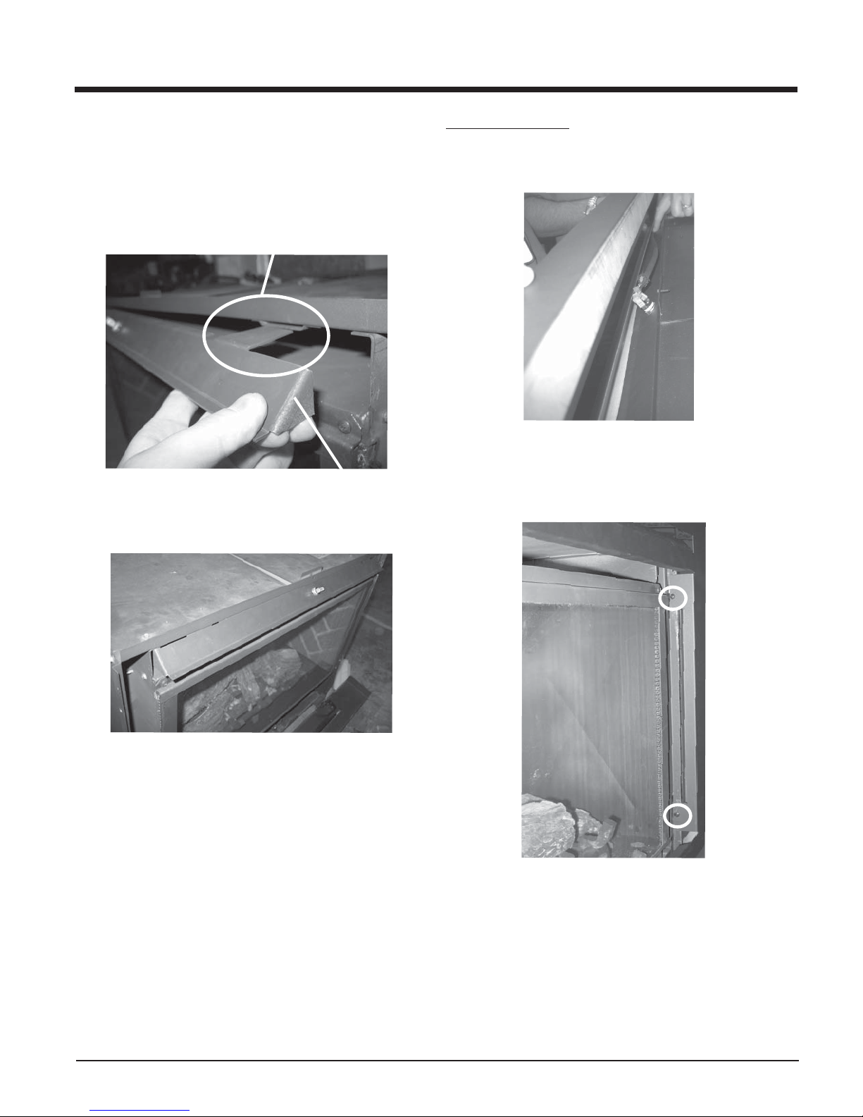
18) Install the heat defl ector to the unit by fi tting the tabs into the tab
brackets located on the underside of the fi rebox. See diagram
16. Diagram 17 shows defl ector completely installed.
Tab into Tab Bracket
INSTALLATION
Faceplate Installation:
19) Completely mount the faceplate to the unit. See diagram 18.
Diagram 18
Diagram 16
Diagram 17
Heat Defl ector
20) Secure the faceplate in place using 2 screws on the left and right
side. Diagram 19 shows mounting on right side.
Diagram 19
Regency I35 Gas Inbuilt Fireplace
17
Page 18
INSTALLATION
Louver Installation:
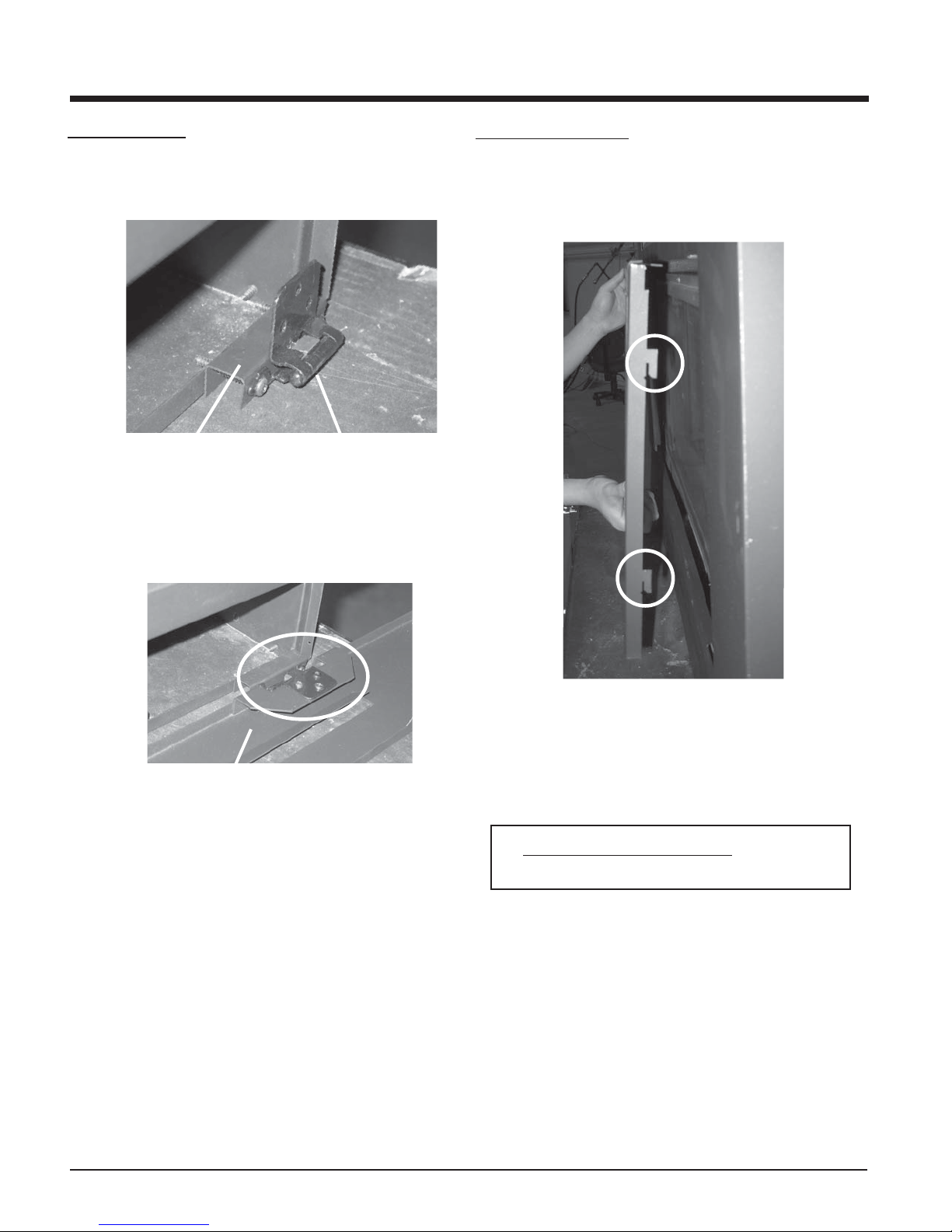
21) Secure the hinge bracket and hinge to the outside of the fi rebox fl ange
on the left and right side as shown using 2 screws on each side. See
diagram 20.
Hinge Bracket
Diagram 20
22) Align the bottom louver hinge tab screw holes with hinge screw holes
and secure using 3 screws on each side. See diagram 21.
Hinge
Screen Door Installation:
23) Re-install the glass door.
24) Install the screen by placing the hooks (2 on each side) into the slots
on the inside of the faceplate. Once in place, push down on the screen
to secure. See diagram 22.
Bottom Louver
Diagram 21
Diagram 22
25) Close the bottom louver.
26) Plug in the power source.
NOTE:
The fan should run at least on low speed to prevent the unit
from overheating which will cause automatic shutdown via the
thermodisc safety switch.
18
Regency I35 Gas Inbuilt Fireplace
Page 19
INSTALLATION
OPTIONAL WALL
THERMOSTAT
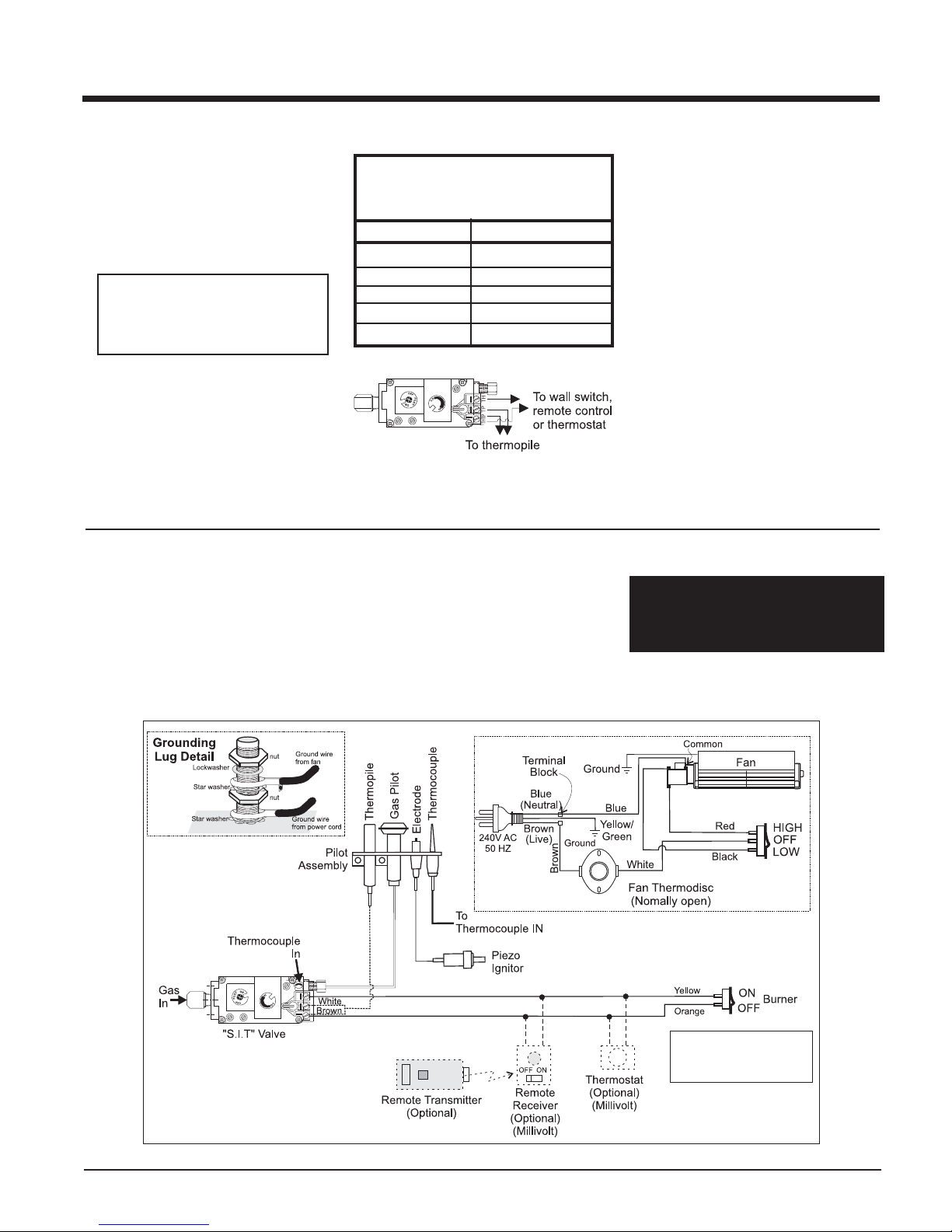
A wall thermostat may be installed if desired.
Connect the wires as per the wiring diagrams.
Note that the wires are connected to the "TH"
on the gas valve. Use table below to determine
the maximum wire length:
CAUTION
Do not connect the millivolt
wall thermostat wires
to the 240V wires.
This heater does not require a 240V A.C. supply
for the gas control to operate. A 240V A.C. power
supply is needed for the fan/blower operation.
Thermostat Wire Table
Recommended Maximum Lead Length
(Two-Wire) When Using Wall
Thermostat (CP-2 System)
Wire Size Max. Length
14 GA.
16 GA.
18 GA.
20 GA.
22 GA.
15.24 m
9.75 m
6.10 m
3.66 m
2.71 m
WIRING
Caution: Ensure that the wires do not
touch any hot surfaces and are away
from sharp edges.
FINAL CHECK
Before leaving this unit with the customer, the
installer must ensure that the appliance is fi ring
correctly. This includes:
1) Clocking the appliance to ensure the correct fi ring rate (rate noted on label) at 15
minutes.
2) If required, adjusting the primary air to
ensure that the fl ame does not carbon.
First allow the unit to burn for 15 min. to
stabilize.
3) Check for proper draft.
CAUTION
Any alteration to the product that
causes sooting or carboning that
results in damage to the exterior
facia is not the responsibility of the
manufacturer.
CAUTION: Label all wires prior to disconnection when servicing controls.
Wiring errors can cause improper and
dangerous operation.
STANDARD WIRING
NOTE: Switch must be
in "OFF" position to
operate remote.
Regency I35 Gas Inbuilt Fireplace
19
Page 20
INSTALLATION
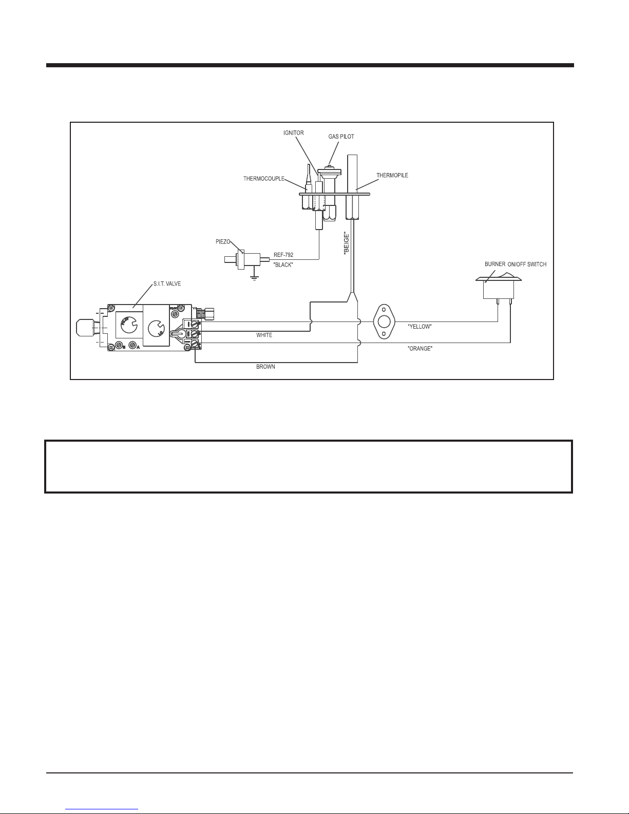
WIRING WITH PREMIUM FLUSH FRONT OPTION
WARNING: Electrical Grounding Instructions
This appliance is equipped with a three pronged (grounding) plug for your protection against shock hazard and should
be plugged directly into a properly grounded three-prong receptacle. Do not cut or remove the grounding prong from
this plug.
20
Regency I35 Gas Inbuilt Fireplace
Page 21

OPERATING INSTRUCTIONS
OPERATING
INSTRUCTIONS
Before operating this appliance, proceed through
the following check list.
1) Read and understand these Instructions
before operating this appliance.
2) Check to see that all wiring is correct and
enclosed to prevent possible shock.
3) Check to ensure there are no gas leaks.
4) Make sure the three pieces of door glass
are properly positioned. Never operate the
appliance with any of the glass removed or
with the door open.
5) Verify that all fl uing and the cap is unob-
structed.
6) Verify log placement. If the pilot cannot be
seen when lighting the unit - the logs or the
embers have been incorrectly positioned.
7) The unit should never to turned off and on
without a minimum of a 60 second wait.
LIGHTING
PROCEDURE
IMPORTANT: Gas on/off knob cannot be
turned from "PILOT" to "OFF" unless it is
partially depressed.
SHUTDOWN
INSTRUCTIONS
1) Turn OFF the fl ame switch.
2) Push in gas control knob slightly and turn to
"OFF" position.
FIRST FIRE
The FIRST FIRE is part of the paint curing proc-
ess. To ensure that the paint is properly cured,
it is recommended that you burn your fi replace
for at least four (4) hours the fi rst time you use it
with the fan on. When fi rst operated, the unit will
release an odour caused by the curing of the paint
and the burning off of any oils remaining from
manufacturing. Smoke detectors in the house
may go off at this time. Open a few windows
to ventilate the room for a couple of hours. The
glass may require cleaning.
DO NOT ATTEMPT TO CLEAN THE
GLASS WHILE IT IS STILL HOT!
Note: When the glass is cold and the appli-
ance is lit, it may cause condensation
and fog the glass. This condensation
is normal and will disappear in a few
minutes as the glass heats up.
DO NOT BURN THE APPLIANCE
WITHOUT THE GLASS FRONT IN
PLACE.
AUTOMATIC
CONVECTION FAN
OPERATION
Set the fan speed on control panel at the top
left side of the unit to adjust to the desired
speed. The fan will turn on as the stove comes
up to operating temperature. After the unit has
been turned off and the unit cooled to below a
useful heat output range the fan will shut off
automatically.
ADJUSTING FLAME
HEIGHT
Your heater has an adjustable fl ame to tailor
the look and heat output to your specifi c needs.
It is adjusted by turning the fl ame adjustment
dial on the gas control valve.
Turn clockwise to adjust the fl ame higher ,
counterclockwise for a lower fl ame.
1) Turn burner OFF using "ON/OFF" switch.
2) Turn gas control knob so indicator points
to "OFF" position and allow 5 minutes for
any gas in the combustion chamber to
escape.
3) Turn gas control knob counterclockwise
so indicator points to the "PILOT" position.
Depress the gas control knob fully. Depress
the igniter button several times until the
pilot lights. After approximately one minute,
release the gas control knob. The pilot fl ame
should continue to burn. If the pilot does not
remain lit, repeat operation allowing a longer
period before releasing gas control knob.
4) When the pilot stays lit, turn the gas knob
further counterclockwise to the "ON" position.
5) Use the ON/OFF switch, wall switch, thermostat or remote control to turn on the unit.
6) Rotate the fl ame height regulator (Hi/Lo) to
adjust the fl ame height higher or lower.
During the fi rst few fi res, a white fi lm
may develop on the glass front as part
of the curing process. The glass should
be cleaned or the fi lm will bake on and
become very diffi cult to remove. Use a
non-abrasive cleaner and NEVER clean
the glass while it is hot.
Regency I35 Gas Inbuilt Fireplace
21
Page 22
OPERATING INSTRUCTIONS
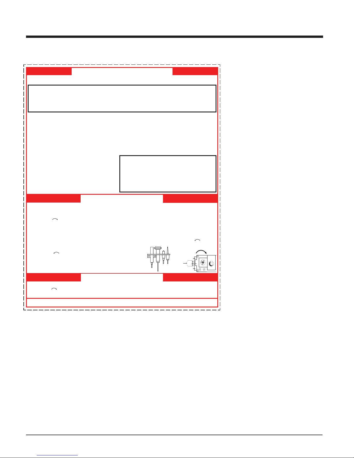
1) Push in the gas control knob slightly and turn
clockwise to OFF. Do not force.
FOR YOUR SAFETY READ BEFORE LIGHTING
A) This appliance has a pilot which must be lighted
by hand, following the instructions below
exactly.
B) BEFORE LIGHTING smell all around the appliance
area for gas. Be sure to smell next to the floor
because some gas is heavier than air and will
settle on the floor.
WHAT TO DO IF YOU SMELL GAS
- Do not try to light any appliance
- Do not touch any electric switch, do not use any
phone in your building
- Immediately call your gas supplier from a
neighbors phone. Follow the gas suppliers instructions.
- If you cannot reach your gas supplier, call the
fire department.
C) Use only your hand to push in or turn the gas
control knob. Never use tools. If the knob will not
push in or turn by hand, dont try to repair it, call
STOP! Read the safety information above on this
label.
1)
Push in gas control knob slightly and turn
clockwise
to OFF. Knob cannot be turned
from PILOT to OFF unless knob is pushed in
slightly. Do not force.
2) Wait five (5) minutes to clear out any gas. If you
then smell gas STOP! follow B in the safety
information above on this label. If you dont smell
gas, go to the next step.
3) Turn knob on gas control counterclockwise
to PILOT.
4) Push in control knob all the way and hold in.
Immediately push black button on spark igniter
until pilot lights. Continue to hold the control
knob in for about 1/2 minute after the pilot is lit.
Release knob and it will pop back up. Pilot should
remain lit. If it goes out, repeat steps 3) and 4).
If knob does not pop up when released, stop and
immediately call your service technician or gas
supplier.
If the pilot will not stay lit after several tries, turn the
gas control knob to OFF and call your service
technician or gas supplier.
5) Turn gas control knob counterclockwise to ON.
6) Use rocker switch to operate main burner.
908-649c
OFF
WARNING:
If you do not follow these instructions exactly, a fire or explosion may result causing
property damage, personal injury or loss of life. Improper installation, adjustment, alteration, service
or maintenance can cause injury or property damage. Refer to the owners information manual
provided with this appliance. For assistance or additional information consult a qualified installer,
service agency or gas supplier.
a qualified service technician. Force or attempted
repair may result in a fire or explosion.
D) Do not use this appliance if any part has been under
water. Immediately call a qualified service technician to inspect the appliance and to replace any part
of the control system and any gas control which has
been under water.
This appliance needs fresh air for safe operation and
must be installed so there are provisions for adequate
combustion and ventilation air.
LIGHTING INSTRUCTIONS
TO TURN OFF GAS APPLIANCE
THERMOPILE
ELEMENT
THERMO-
ELECTRIQUE
PILOT BURNER
VEILLEUSE
This appliance must be installed in accordance with local codes, if any; if none, follow the National Fuel Gas Code, ANSI
Z223.1/NFPA 54, or Natural Gas and Propane Installation Codes, CSA B149.1. (Australia: AS5601-2004, New Zealand: NZS 5261)
DO NOT REMOVE THIS INSTRUCTION PLATE
CAUTION: Hot while in operation. Do not touch.
Severe Burns may result. Due to high surface
temperatures keep children, clothing and
furniture, gasoline and other liquids having
fammable vapors away. Keep burner and control
compartment clean. See installation and
operating instructions accompanying appliance.
2) Turn off all electric power to the appliance if
service is to be performed.
You may shut off the pilot during prolonged non use periods to conserve fuel.
COPY OF LIGHTING INSTRUCTION PLATE
22
Gas Inlet
NORMAL
OPERATING SOUNDS
OF GAS APPLIANCES
It is possible that you will hear some sounds
from your gas appliance. This is perfectly normal
due to the fact that there are various gauges
and types of steel used within your appliance.
Listed below are some examples. All are normal
operating sounds and should not be considered
as defects in your appliance.
Blower:
Regency gas appliances use high tech blowers
to push heated air farther into the room. It is not
unusual for the fan to make a "whirring" sound
when ON. This sound will increase or decrease
in volume depending on the speed setting of
your fan speed control.
Burner Tray:
The burner tray is positioned directly under the
burner tube(s) and logs and is made of a different gauge material from the rest of the fi rebox
and body. Therefore, the varying thicknesses of
steel will expand and contract at slightly different
rates which can cause "ticking" and "cracking"
sounds. Y ou should also be aware that as there
are temperature changes within the unit these
sounds will likely re-occur. Again, this is normal
for steel fi reboxes.
Blower Thermodisc:
When this thermally activated switch turns ON
it will create a small "clicking" sound. This is the
switch contacts closing and is normal.
Pilot Flame:
While the pilot fl ame is on it can make a very
slight "whisper" sound.
Gas Control Valve:
As the gas control valve turns ON and OFF, a
dull clicking sound may be audible, this is normal
operation of a gas regulator or valve.
Unit Body/Firebox:
Different types and thicknesses of steel will
expand and contract at different rates resulting
in some "cracking" and "ticking" sounds will be
heard throughout the cycling process.
Regency I35 Gas Inbuilt Fireplace
Page 23
MAINTENANCE
MAINTENANCE
INSTRUCTIONS
1) Always turn off the valve before cleaning.
For relighting, refer to lighting instructions.
Keep the burner and control compartment
clean by brushing and vacuuming at least
once a year. When cleaning the logs, use a
soft clean paint brush as the logs are fragile
and easily damaged.
2) Clean glass (never when unit is hot), appliance, louvres, and door with a damp cloth.
Never use an abrasive cleaner. The gold
louvres (and optional gold door) may be
scratched if abrasives are used to clean
them.
The heater is fi nished in a heat resistant
paint and should only be refi nished with
heat resistant paint (not with wall paint).
This stove uses StoveBright Paint - Metallic
Black #6309.
3) Make a periodic check of burner for proper
position and condition. Visually check the
fl ame of the burner periodically, making sure
the fl ames are steady; not lifting or fl oating. If
there is a problem, call an authorized service
person.
4) Caution: Label all wires prior to disconnection
when servicing controls. Wiring errors can
cause improper and dangerous operation.
5) The appliance and fl uing system must be
inspected before use, and at least annually, by an authorized fi eld service person,
to ensure that the fl ow of combustion and
ventilation air is not obstructed.
During the annual service call, the burners
should be removed from the burner tray
and cleaned. Replace the embers but do
not block the pilot.
6) Keep the area near the appliance clear and
free from combustible materials, gasoline,
and other fl ammable vapours and liquids.
WARNING: CHILDREN AND
ADULTS SHOULD BE ALERTED
TO THE HAZARDS OF HIGH
SURFACE TEMPERATURE AND
SHOULD STAY AWAY TO AVOID
BURNS OR CLOTHING IGNITION.
YOUNG CHILDREN SHOULD BE
CAREFULL Y SUPERVISED WHEN
THEY ARE IN THE SAME ROOM
AS THE APPLIANCE.
DO NOT USE THIS APPLIANCE
IF ANY P ART HAS BEEN UNDER
WA TER. IMMEDIA TEL Y CALL AN
AUTHORIZED SERVICE TECHNICIAN TO INSPECT THE APPLIANCE AND TO REPLACE ANY
PART OF CONTROL SYSTEM
AND ANY GAS CONTROL WHICH
HAS BEEN UNDER WATER.
CAUTION: ANY SAFETY SCREEN
OR GUARD REMOVED FOR
SERVICING AN APPLIANCE
MUST BE REPLACED PRIOR TO
OPERATING THE APPLIANCE.
CLOTHING OR OTHER FLAMMABLE MATERIAL SHOULD NOT
BE PLACED ON OR NEAR THE
APPLIANCE.
7) Each time the appliance is lit, it may cause
condensation and fog the glass. This
condensation and fog is normal and will
disappear in a few minutes as the glass
heats up.
Never operate the appliance without the
glass properly secured in place or with
the door open.
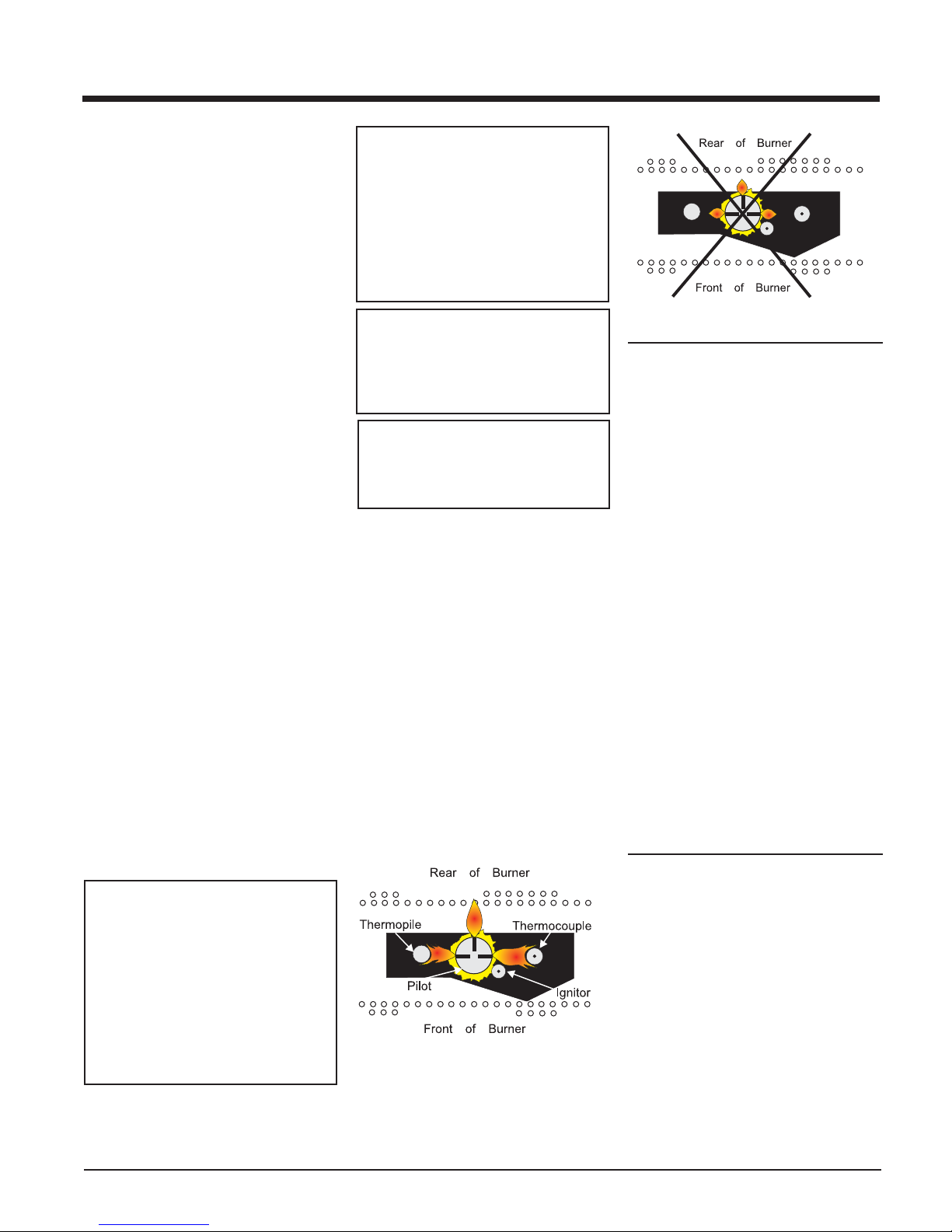
8) Periodically check the pilot fl ames. Correct
fl ame pattern has three strong blue fl ames: 1
fl owing around the thermopile and 1 around
the thermocouple, and 1 fl owing across the
rear of the burner (it does not have to be
touching the burner).
Note: If you have an incorrect fl ame pat-
tern, contact your Masport dealer for
further instructions.
Top View of pilot fl ame
Incorrect fl ame pattern will have small, probably
yellow fl ames, not coming into proper contact
with the rear of the burner or thermopile.
Top View of pilot fl ame
GENERAL FLUE
MAINTENANCE
Conduct an inspection of the fl uing system
semi-annually. Recommended areas to inspect
as follows:
1) Check the Fluing System for corrosion in areas that are exposed to the elements. These
will appear as rust spots or streaks, and in
extreme cases, holes. These components
should be replaced immediately.
2) Remove the Cap, and shine a fl ashlight down
the Flue. Remove any bird nests, or other
foreign material.
3) Check for evidences of excessive condensation, such as water droplets forming in the
inner liner, and subsequently dripping out the
joints, Continuous condensation can cause
corrosion of caps, pipe, and fi ttings. It may
be caused by having excessive lateral runs,
too many elbows, and exterior portions of the
system being exposed to cold weather.
4) Inspect joints, to verify that no pipe sections
or fi ttings have been disturbed, and conse-
quently loosened. Also check mechanical
supports such as Wall Straps, or plumbers'
tape for rigidity.
LOG REPLACEMENT
The unit should never be used with broken logs.
Turn off the gas valve and allow the unit to cool
before opening door to carefully remove the logs.
The pilot light generates enough heat to burn
someone. If for any reason a log should need
replacement, you must use the proper replacement log. The position of these logs must be as
shown in the diagram under Log Installation.
Note: Improper positioning of logs may
create carbon build-up and will alter
the unit’s performance which is not
covered under warranty.
Regency I35 Gas Inbuilt Fireplace
23
Page 24
MAINTENANCE
FAN MAINTENANCE
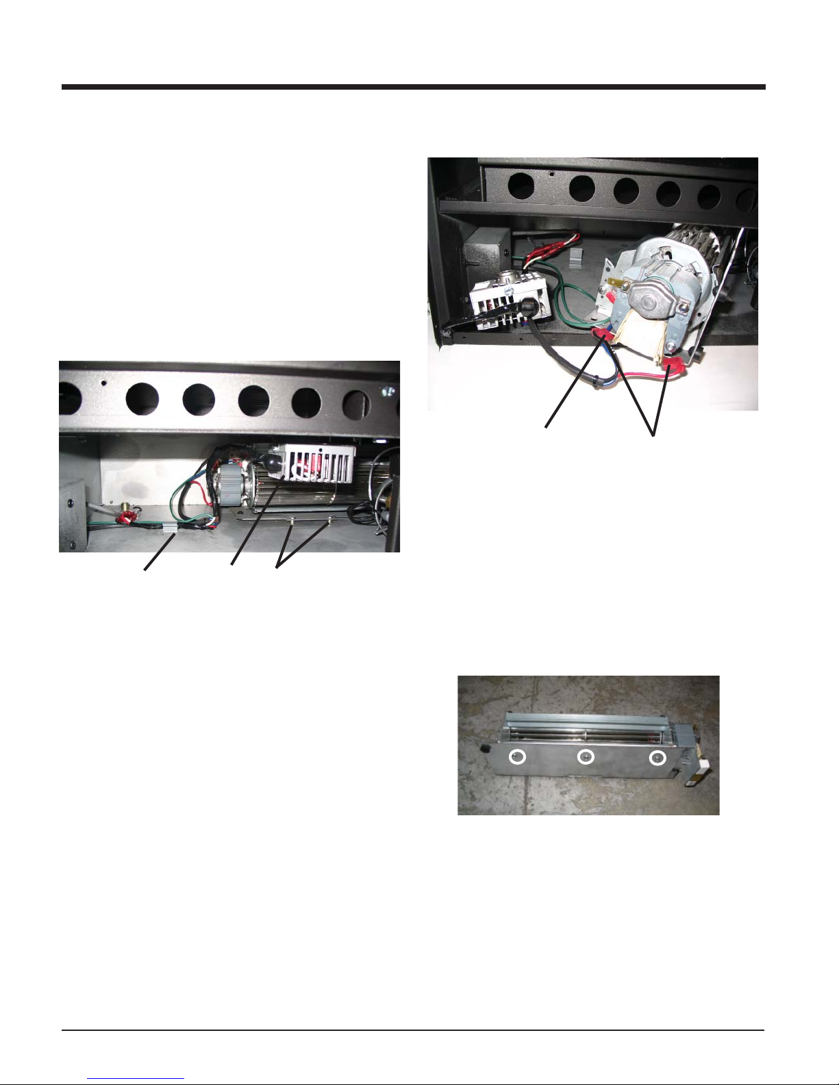
To Remove Fan:
1) Turn the unit off and allow it to cool to room temperature,
2) Unplug or disconnect power source to stove.
3) Open the bottom louver.
4) Remove the fan harness from the back clip.
5) Remove the 2 screws that secure the fan in place.
6) Pull out the fan thermodisc block.
7) Carefully slide the fan to the front, rotate it 45 degrees and slide it out
simultaneously with the fan thermodisc block.
Fan Ground
Cable
8) Disconnect all the connectors from the fan and resistor.
Fan
Connectors
Back Clip
Fan
Thermodisc
Block
Fan
Screws
9) Remove the fan ground cable.
10) Pull out the fan tray.
11) Remove the 3 screws from the back of the fan tray to remove the
fan.
12) Reverse the above steps to install the new fan.
24
Regency I35 Gas Inbuilt Fireplace
Page 25
MAINTENANCE
REMOVING
VALVE TRAY
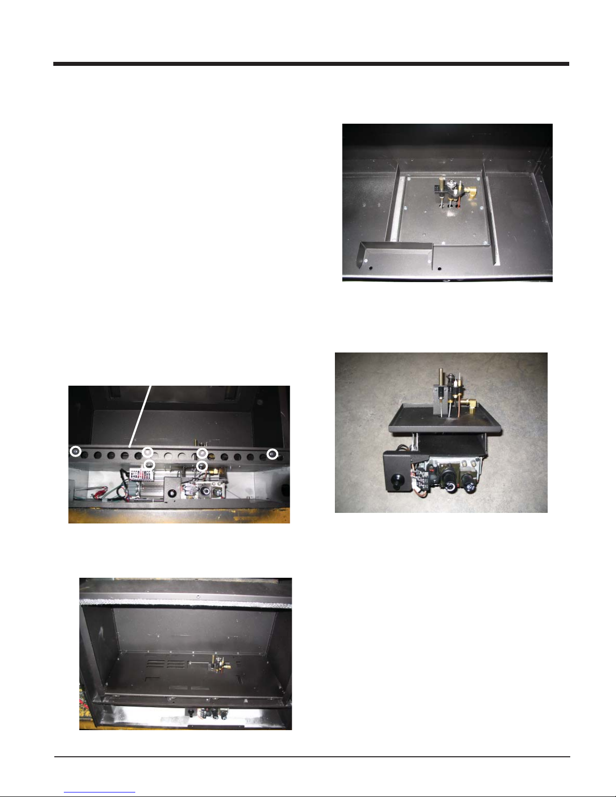
1) Unplug or disconnect the power source to the stove.
2) Shut off the gas supply and remove the gas connection from the
valve.
3) Remove the top louver.
4) Remove the safety screen.
5) Remove the screen door.
6) Remove the logs.
7) Remove the brick panels.
8) Remove the rear log tray.
9) Remove the grate.
10) Remove the burner.
11) Remove the glass door holder by removing 4 screws on the front
and 2 on the bottom.
Glass Door
Holder
13) Remove the thermostat wires from the valve.
14) Remove the 8 screws which secure the valve tray.
15) Remove the valve tray assembly.
12) Remove the fi rebox base plate by removing 11 screws which hold
it in place.
Regency I35 Gas Inbuilt Fireplace
16) To replace the valve tray assembly, simply reverse the above
steps.
25
Page 26

PARTS LIST
MAIN ASSEMBLY
Part # Description Part # Description
1) 910-169/P Fan Motor (240 V)
2) 910-714 Power Cord 240 Volts
3) 820-389 Thermodisc Bracket
4) 910-142 Thermodisc-Fan Auto ON/OFF
5) 910-006 Terminal Block
6) * Levelling Bolts 5/16 x 3 Hex Head
948-216 Logo Plate
918-464 Manual
7) 486-910 Flush Louvre set - Black (Top & Bottom)
486-904 Brick Panel (Set)
8) * Brick Panel - Back
9) * Brick Panel - Left Side
10) * Brick Panel - Right Side
11) 511-031 Brick Clips
12) 936-233 3/4" Rope Gasket
13) 486-968 LPG Conversion Kit
486-967 ULPG Conversion Kit
*Not available as a replacement part.
BURNER ASSEMBLY & LOG SET
Part # Description Part # Description
486-574/P Valve Assembly - NG
486-576/P Valve Assembly - LPG
52) 910-478 SIT Valve NG/LP
53) 910-190 Piezo Ignitor and nut
54) * Valve Heat Shield
56) * Pilot Bracket
57) 904-689 Burner Orifi ce NG #33
904-645 Burner Orifi ce LPG # 51
60) 486-048 Grate Assembly
62) 486-535 Burner Assembly - NG/LPG
63) 910-034 Pilot Assy (NG) - 3 fl ame convertible top
910-035 Pilot Assy (LPG) - 3 fl ame convertible top
69) 730-935 Log Set
486-930 Log/Ember Package
86) 910-386 Thermocouple
87) 910-341 Thermopile
92) * Rear Log
93) * Left Top Log
94) * Center Log
95) * Middle Right Log
96) * Middle Left Log
97) * Front Right Log
98) * Front Left Log
*Not available as a replacement part.
26
Regency I35 Gas Inbuilt Fireplace
Page 27

PARTS LIST
F ACEPLATE ASSEMBLY
Part # Description Part # Description
87) 910-140 Fan HI/OFF/LOW Switch
88) 910-246 Burner ON/OFF Switch
486-918 Faceplate & Trim Complete - Regular
91) * Faceplate Side Right - Regular
92) * Faceplate Top - Regular
93) * Faceplate Side Left - Regular
Trims Packaged - Regular
94) * Faceplate Trim Right - Regular
95) * Faceplate Trim Top - Regular
96) * Faceplate Trim Left Assy - Regular
176) 486-926 Hearth Trim 2" - Regular
180) 486-928 Hearth Trim 4" - Regular
181) 486-929 Flush Screen Door
*Not available as a replacement part.
PREMIUM FLUSH FRONT ASSEMBLY
Part # Description
486-916 Premium Flush Front - Black
486-948 Wiring
486-932 Flue Free Kit
910-987 Thermodisc
200) * Screen
201) * Heat Defl ector
202) * Heat Shield
*Not available as a replacement part.
Regency I35 Gas Inbuilt Fireplace
27
Page 28

NOTES
___________________________________________________
___________________________________________________
___________________________________________________
___________________________________________________
___________________________________________________
___________________________________________________
___________________________________________________
___________________________________________________
___________________________________________________
___________________________________________________
___________________________________________________
___________________________________________________
___________________________________________________
___________________________________________________
___________________________________________________
___________________________________________________
___________________________________________________
___________________________________________________
___________________________________________________
___________________________________________________
___________________________________________________
___________________________________________________
___________________________________________________
___________________________________________________
28
Regency I35 Gas Inbuilt Fireplace
Page 29

NOTES
___________________________________________________
___________________________________________________
___________________________________________________
___________________________________________________
___________________________________________________
___________________________________________________
___________________________________________________
___________________________________________________
___________________________________________________
___________________________________________________
___________________________________________________
___________________________________________________
___________________________________________________
___________________________________________________
___________________________________________________
___________________________________________________
___________________________________________________
___________________________________________________
___________________________________________________
___________________________________________________
___________________________________________________
___________________________________________________
___________________________________________________
___________________________________________________
Regency I35 Gas Inbuilt Fireplace
29
Page 30

NOTES
___________________________________________________
___________________________________________________
___________________________________________________
___________________________________________________
___________________________________________________
___________________________________________________
___________________________________________________
___________________________________________________
___________________________________________________
___________________________________________________
___________________________________________________
___________________________________________________
___________________________________________________
___________________________________________________
___________________________________________________
___________________________________________________
___________________________________________________
___________________________________________________
___________________________________________________
___________________________________________________
___________________________________________________
___________________________________________________
___________________________________________________
___________________________________________________
30
Regency I35 Gas Inbuilt Fireplace
Page 31

WARRANTY
Regency Fireplace Products are designed with reliability and simplicity in mind. In addition, our internal
Quality Assurance Team carefully inspects each unit
thoroughly before it leaves our door. Regency Industries Ltd. is pleased to extend this limited lifetime warranty to the original purchaser of a Regency Product.
The Warranty: Lifetime
Covered under the agreement are the following components:
Combustion chamber, heat exchanger , burner tubes, logs,
embers, glass (thermal breakage) and all gold plating
(against defective manufacture).
The above will be covered for parts and labour for the fi rst
fi ve years and parts only thereafter.
Electrical components such as fans, switches, wiring,
thermodiscs, remote control, thermopiles, thermocouples
and gas valves are covered for one year from the date of
purchase.
Conditions:
All installations must be performed by an authorised gas fi tter
and installed according to all applicable local and national
codes. Also, all service work must be carried out by an
authorised gas service person. It is the responsibility of the
installer to ensure that the appliance is fi ring as per rating
plate. Any part or parts of this unit which in our judgement
show evidence of such defect will be repaired or replaced
at Regency's option, through an accredited distributor or
agent provided that the defective part be returned to the
distributor or agent Transportation Prepaid, if requested.
In areas where there is not an approved service agent or
the closest approved service agent is situated more than
thirty (30) kilometres from the installation,Regency is not
obliged to arrange warranty repairs and travel and/or additional labour charges will apply.
Exclusions:
This limited Lifetime Warranty does not extend to or
include paint, door or glass gasketing or trim. It does
not cover installation and operational related problems
such as over-fi ring, downdrafts or spillage caused by en-
vironmental conditions, nearby trees, buildings, hilltops,
mountains, inadequate fl ueing or ventilation, excessive
offsets, negative air pressures caused by insuffi cient
make up air, mechanical systems such as furnaces, fans,
clothes dryers etc.
The warranty does not extend to any part or parts which
show evidence of misuse or abuse, neglect, accident or
lack of maintenance.
Products made by other manufacturers and used in
conjunction with the operation of this appliance without
authorization from Regency, may nullify your warranty
on this product.
Regency Fireplace Products, shall in no event be liable
for any special, indirect consequential damages of any
nature whatsoever which are in excess of the original
purchase price of the product. Any alteration to the unit
which causes sooting or carboning that results in damage
to the exterior facia is not the responsibility of Regency
Fireplace Products.
General:
It is essential that all submitted claims provide all of the
necessary information including purchase date, serial #,
type of unit and part or parts requested.
DISTRIBUTORS: Western Australia Eastern Australia
NOTE: PLEASE RETAIN YOUR INVOICE AS PROOF OF PURCHASE FOR WARRANTY
INCORRECT INSTALLATION OR GAS PRESSURE SETTINGS ARE NOT COVERED BY
A SERVICE OR CALLOUT FEE WILL BE CHARGED IN THESE CIRCUMSTANCES.
Regency I35 Gas Inbuilt Fireplace
Air Group Australia
28-30 Division St.
Welshpool, WA 6106 Hallam, VIC 3803
08 9350 2200 03 9799 7277
VERIFICATION
WARRANTY
Fireplace Products Australia PTY. Ltd.
1-3 Conquest Way
31
Page 32
Register your Regency® warranty online
www.regency-fi re.com.au
Reasons to register your product online today!
• View and modify a list of all your registered products.
• Request automatic email notifi cation of new product updates.
• Stay informed about the current promotions, events, and special
offers on related products.
• Help assure you get the most out of your warranty.
• Eliminate confusion and frustration if warranty** service is required in
the future.
** Proof of purchase required at time of warranty request.
Installer: Please complete the following information
Dealer Name & Address: ______________________________________________
___________________________________________________________________
Installer: ___________________________________________________________
Phone #: ___________________________________________________________
Date Installed: ______________________________________________________
Serial No.: __________________________________________________________
© Copyright 2014, FPI Fireplace Products International Ltd. All rights reserved.
Printed in Canada
 Loading...