

Page 1
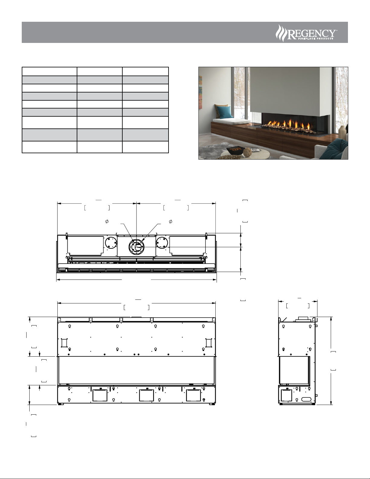
City Series CB72EPV Gas Fireplace
11
1
260mm
1169mm
7
7
Model CB72EPV-NG CB72EPV-LP
Fuel Type Natural Gas Propane
Minimum Supply Pressure 5” W.C. (1.25 kPa) 11” W.C. (2.73 kPa)
Manifold Pressure - High 3.5” W.C. (0.87 kPa) 10” W.C. (2.49 kPa)
Manifold Pressure - Low 1.6” W.C. (0.40 kPa) 6.4” W.C. (1.59kPa)
Orice Size -Altitude 0-4500 ft. #30 DMS #47 DMS
Minimum Input
Altitude 0-4500 ft. (0-1372m)
Maximum Input
Altitude 0-4500 ft. (0-1372m)
Vent Sizing
32,000 BTU/h
(9.37 kW)
46,500 BTU/h
(13.63 kW)
5” Inner / 8” Outer 5” Inner / 8” Outer
36,000 BTU/h
(10.55 kW)
45,500 BTU/h
(13.33 kW)
"
3
8
187mm
7
41
1052mm
"
41
16
5"
[ 127mm ]
83-7/8"
16
1052mm
8"
[ 203mm ]
"
[ 2130mm ]
13"
82
11
"
16
329mm
2104mm
"
16
525.79mm
20
"
1
16
382mm
15
20
517mm
3
"
8
46"
"
4
10
Page 2
CB72EPV Gas Fireplace
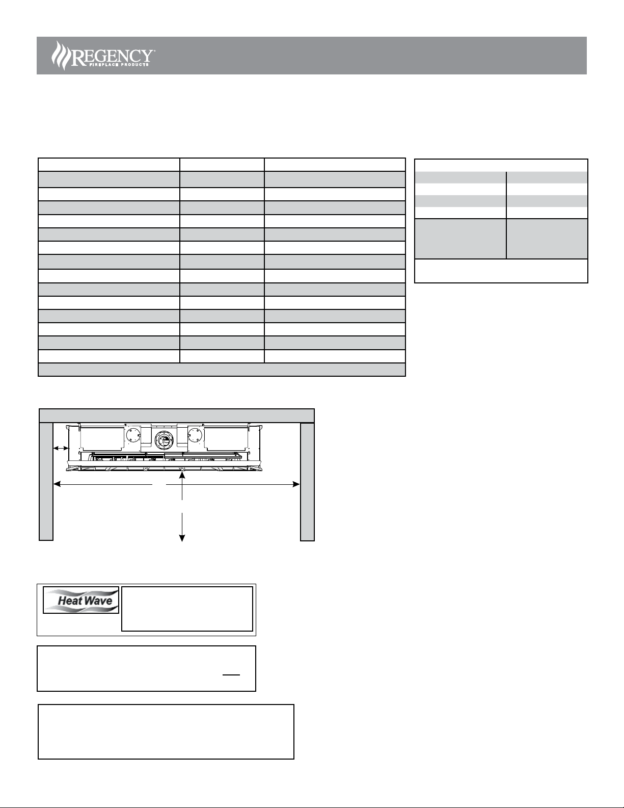
CLEARANCES CB72EPV
The clearances listed below are Minimum distances unless otherwise stated:
A major cause of chimney related res is failure to maintain required clearances (air space) to combustible materials. It is of the greatest importance that
this replace and vent system be installed only in accordance with these instructions.
Clearance: single sided Dimension Measured From:
A1: Mantel Height (min.) ** Top of Fireplace Opening
A: From Floor min. 0" Bottom of Fireplace Opening
B: Sidewall (on one side) Min. 8" (203mm) Side of Fireplace Opening
C: Enclosure Width (min.) 82-11/16" (2100mm) Minimum inside dimensions
D: Mantel Depth (max.) **
E: Alcove Width 120" (3048mm) Sidewall to Sidewall (Minimum)
F: Alcove Depth 36" (914mm) Front to Unit (Maximum)
G: Convection Air Outlet Opening Oset *0-2" (0-51mm) Max. oset from top of chase enclosure
H: Convection Air Outlet *288 square inches
I Enclosure Depth (min.) 20-3/8" (517mm) Minimum inside dimensions
J: Opening Height 15-1/16" (383mm) Bottom/Top of Fireplace Opening
K: To Ceiling (Min.) all 3 sides 2-1/2" (64mm) To Top of Ceiling
L: Chase Enclosure (Min.) 87" (2210mm) From base of unit/oor to top of enclosure
Hearth 0" No hearth required
** See mantel clearances chart in unit manual.
B
Flue Clearances to Combustibles
Horizontal - Top 3"
Horizontal - Side 2"
Horizontal - Bottom 2"
Vertical 2"
Passing through wall/
floor/ceiling - when
restop is used.
Note: This appliance uses 4" x 6-5/8" venting
1-1/2"
E
F
Alcove
The HeatWave Duct Kit has
different clearance and framing
requirements, check the HeatWave
manual for details.
The top, back and sides of the replace are dened by
standos. The metal ends of the stando may NOT be
if these clearances (air space) to combustible materials are not
adhered to. It is of greatest importance that this replace and vent
system be installed only in accordance with these instructions.
Caution Requirements
recessed into combustible construction.
WARNING
Fire hazard is an extreme risk
Page 3
CB72EPV Gas Fireplace
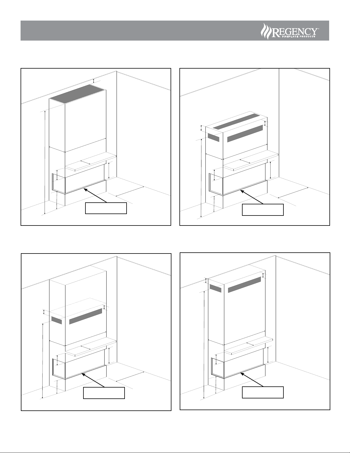
CLEARANCES CB72EPV
K
H
I
L
A1
A
Floor to ceiling with top opening
C
D
J
Bottom of replace
opening
G
H
I
L
B
A1
A
H
H
C
D
Bottom of replace
G
J
B
opening
Low framing with vents in front/sides or top
G
H
H
G
G
H
I
A1
L
A
H
C
D
Bottom of replace
opening
Full framing with low vents in front or sides
G
L
I
J
B
1
A
A
C
D
J
Bottom of replace
opening
Full framing with vents in front or sides
Page 4
CB72EPV Gas Fireplace
212 6 4810
0
14
9
”
15-1/16"
10
20
26
Top of
Fireplace
Opening
12" (305mm)
1/2" Drywall, wood, wood panel, etc.
5-1/8"
To Bottom of
Fireplace
Opening
MANTEL LEG
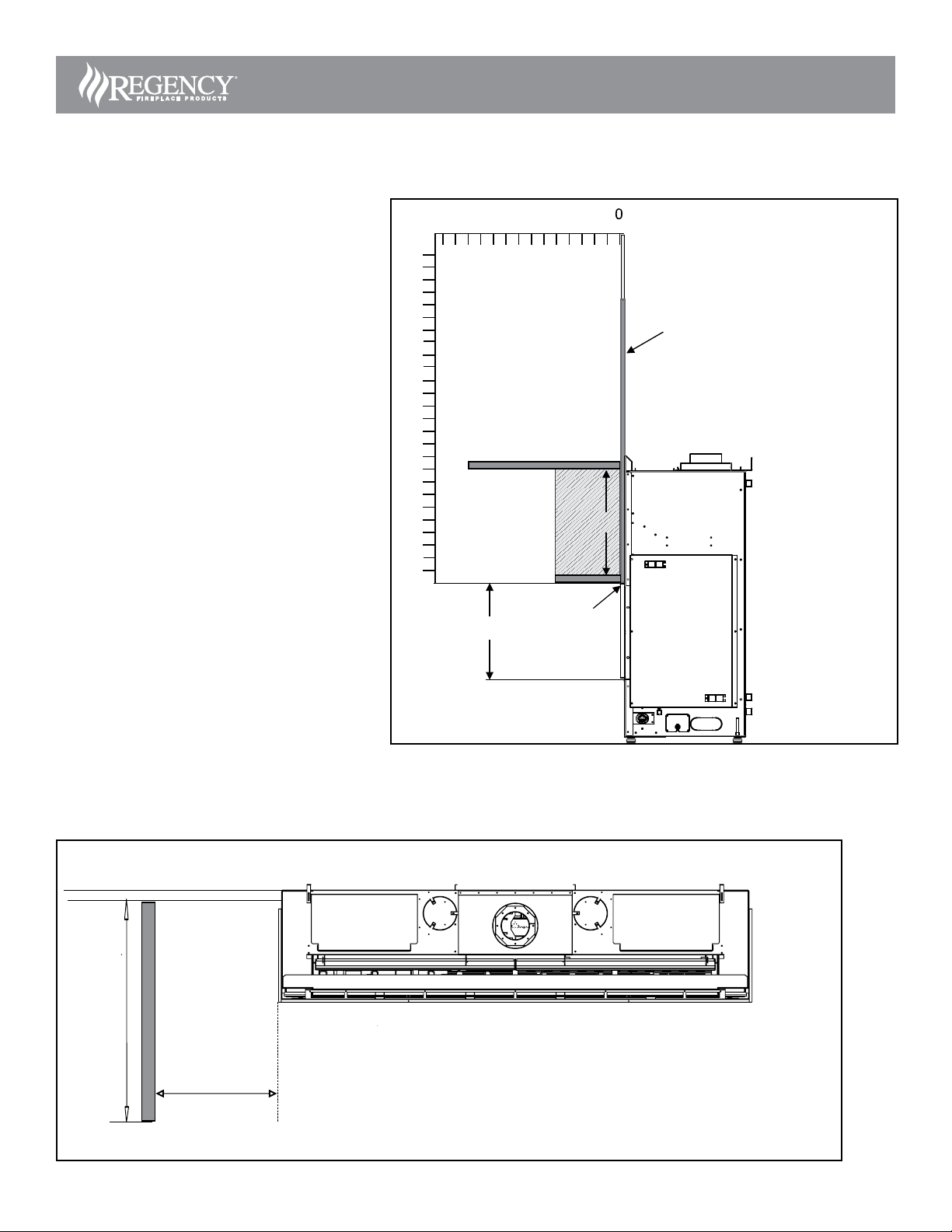
Combustible mantel clearances from top of front facing
are shown in the diagram on the right.
MANTEL CLEARANCES CB72EPV
Combustible mantel leg clearances as per diagram:
12"
8"
MANTEL LEG CLEARANCES
Page 5
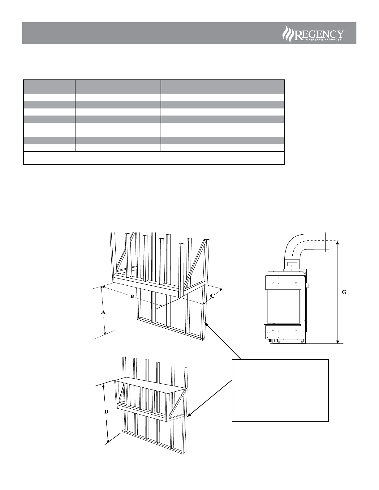
FRAMING DIMENSIONS CB72EPV
NOTE: Framing may be constructed of combustible material (ie. 2 x 4)and does not require steel studs.
CB72EPV Gas Fireplace
Framing
Dimensions
A Framing Height 51" (1295mm)
B Framing Width 82-11/16" (2100mm)
C* Framing Depth 20-5/8" (524mm)
D Minimum Height to Combustibles 87"(2210mm)
G Vent Centerline Height 55-1/4" (1403mm)
** Gas Connection Opening Height See next page
** Gas Connection Height See next page
** Gas Connection Inset-Centre Opening See next page
C* - see not in diagram below
** See next page for alternate Gas/ Electrical connection options
Ensure that the wood base that the appliance will sit on is strong enough to support the full weight of this appliance.
Note: A combined minimum
of 288 square inches of
open area is required for the
convection air outlet to cool the
enclosure. Ensure clearances
for Convection Air Outlets
are met.
See clearances CB72EPV
in this manual as there are
dierent methods as to how
this can be achieved.
Description CB72EPV
Note: This appliance must be
installed on a solid surface
such as a plywood floor
which must be the full width
and depth of the appliance.
Note: Unit must be installed onto a solid
backwall - do not install directly onto studs.
*C
Note : The framing depth does not take into
account drywall/wood or similar materials
against the back wall. The framing depth will
need to change based on the thickness of
the material (example: 20 5/8 framing depth
+ 1/2 drywall = 21 1/8")
Page 6
CB72EPV Gas Fireplace
0
2
4
6
40
8
10
12
14
16
18
20
22
24
26
28
30
32
34
36
38
8
Horizontal (Feet)
4
0
6 10
12
16 181420
22 24
32 342826 30 36 38
Restrictor – Fully Open
2
72' overall length Max.
(shown with 5 - 90º elbows)
72' run (no rise)
72' overall length Max.
(shown with 5 - 90º elbows)
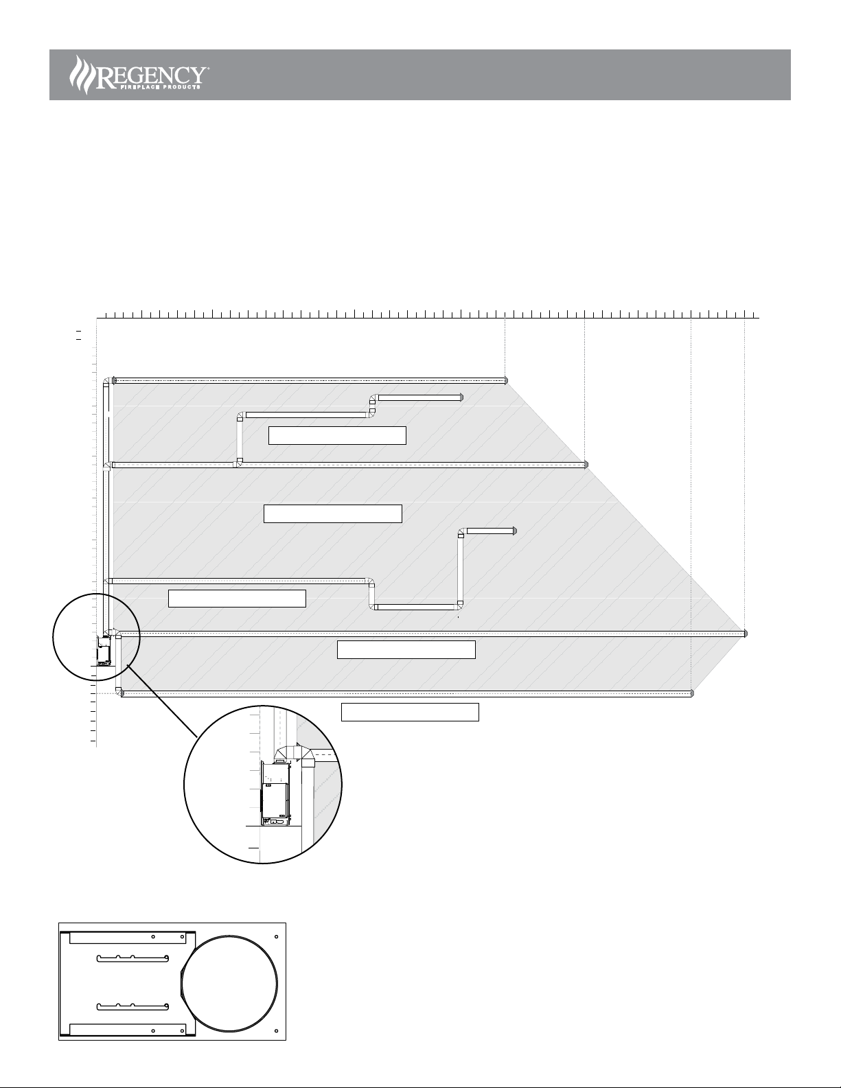
VENTING ARRANGEMENTS FOR HORIZONTAL TERMINATIONS
RIGID PIPE: MUST USE RIGID PIPE ADAPTOR 770-994 AND 946-606 PIPE REDUCER TO 4" X 6 5/8"
Note: Rigid pipe is approved for up to 72 feet.
FLEX VENT: MUST USE REDUCER 946-758 TO 4" X 6 5/8"
Note: Flex pipe is approved for up to 40 feet using 2 X 946-756-- 20 foot ex kits.
The gas power vent system is designed to allow the installation of a gas appliance when typical vent configurations (shown in this manual) are not
possible.
Note: The CB72EPV comes with a 5"inner and 8"outer collar which must be reduced to 4" x 6 5/8" in all applications. Must be terminated horizontally.
Vertical terminations are not permitted.
40
38
36
34
32
30
28
26
24
22
20
18
16
Vertical (Feet)
14
12
10
-3 Ft. max.
6 10
4
2
0
8
6
4
2
0
-2
-4
-6
-8
12
72' overall length Max.
(shown with 5 - 90º elbows)
8
16 181420
22 24
72' overall length Max.
(shown with 5 - 90º elbows)
Restrictor – Fully Open
Shown with 2 elbows (negative run 72')
Horizontal (Feet)
32 342826 30 36 38
40 46 48 50 54 5652 58 60
42 44
62 64 66 68 70
72' run (no rise)
Important: Minimum overall vent run must be 4 feet.
Maximum total vent length = 72' maximum of six - 90° elbows permitted.
One 90° elbow = two 45° elbows.
Maximum total negative vent length = 7'.
Note: Maximum length of 72 feet is based on overall length of combined chimney
components.
72
No Vent Restrictor Required for the CB72EPV
VENT RESTRICTOR POSITION
Set 0
Fully open
Factory Set
Page 7
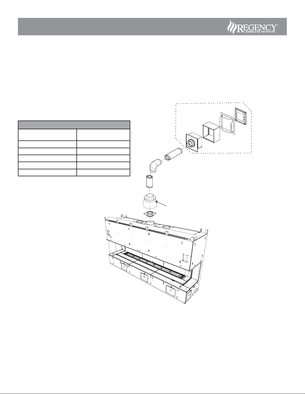
HORIZONTAL TERMINATIONS
RIGID PIPE 4" X 6-5/8"
The minimum components required for a basic horizontal termination
are:
1 Power Vent Kit
1 Rigid Pipe Adaptor
1 Vent Reducer
1 Length of pipe to suit wall thickness and total vent run
(see Table 1)
Wall thickness is measured from the back standos to the inside mounting
surface of termination cap. Create a level surface to mount the vent
terminal. The Terminal must not be recessed into siding. Measure the
wall thickness.
CB72EPV Gas Fireplace
Flat Wall Installation
Wall Thickness
(inches)
4" - 5-1/2" 6"
7" - 8-1/2" 9"
10" - 11-1/2" 12"
9" - 14-1/2' 11" - 14-5/8" Adj. Pipe
15" - 23-1/2" 17" - 24" Adj. Pipe
Table 1
Vent Length Required
(inches)
Adj.Pipe Length
o
90 Elbow
Pipe Length
Vent reducer
(Part #946-606)
Rigid Pipe Adapter
Powervent Kit
(Part #946-535)
Page 8
CB72EPV Gas Fireplace
CV72EPV / CB72EPV
Gas Power Vent Installation CV72EPV / CB72EPV - Rigid Vent
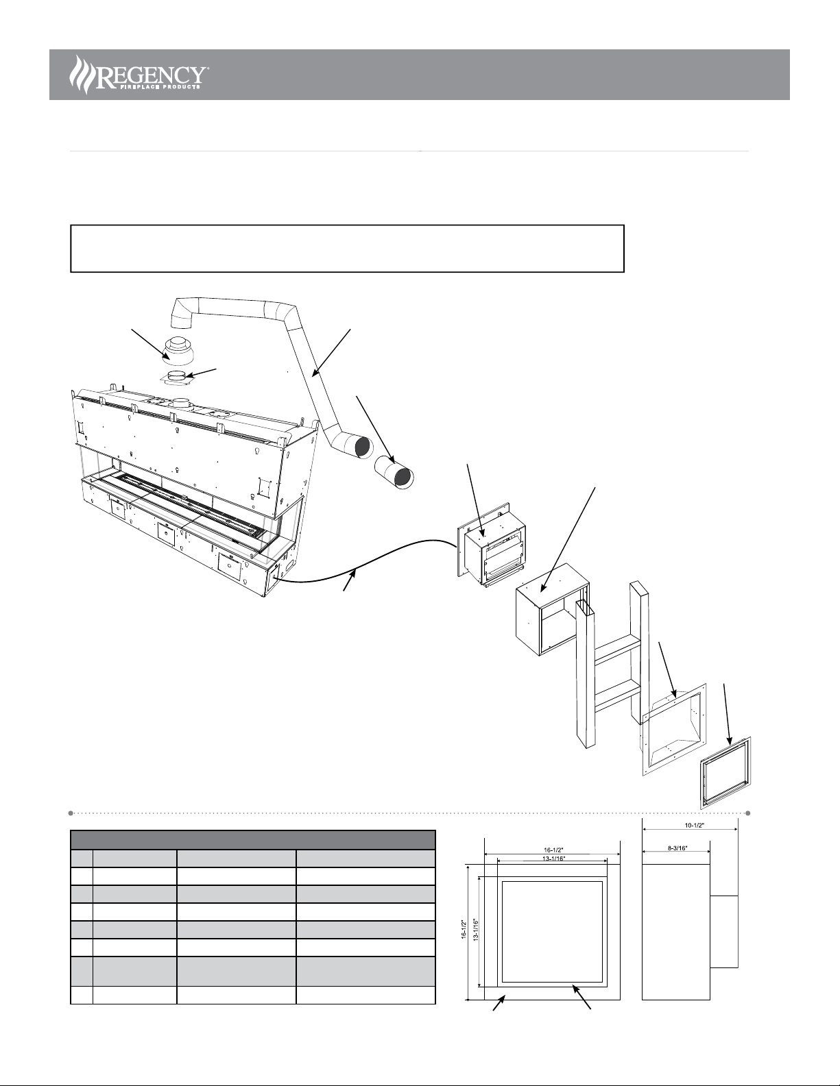
GAS POWER VENT INSTALLATION CB72EPV - RIGID PIPE
The Power Vent System is a Direct Vent Te rminal designed to allow installation of gas appliances where typical vent confi gurations cannot be achieved.
These installation instructions must be used in conjunction with the appliance and appropriate Power Vent components installation instructions.
120 Volt power supply is required to operate this system.
Models Equipped with Surefi re Ignition
The Power Vent system can only be used with units that have been tested with the Regency Power Vent system.
Downward vertical vent runs are permitted with the Surefi re Ignition system. See vent confi guration in unit manual.
Reducer 5" x 8" to
4 " x 6-5/8"
(Required)
(sold separately)
CB72EPV Shown
Rigid Pipe Adaptor
4" x 6-5/8" Rigid pipe lengths
(sold separately)
Slip Section
(sold separately)
Power Vent Terminal
(946-535)
BX Cable
(sold separately)
Frame Assembly
(included w/Power Vent kit)
Power Vent frame
(adjustable depth)
(incl. with Power Vent
kit)
Power Vent trim
(incl. with Power Vent
kit)
946-535 Power Vent Kit with Vent Terminal
1 770-994 Rigid Pipe adaptor sold separately
1 946-606 Reducer (required) sold separately
1Power Vent Fa n included w/Power Vent kit
1Power Vent Frame included w/Power Vent kit
1 911-250/P 45' 5-wire BX cable or sold separately
1 911-251/P 90' 5-wire BX cable sold separately
amount required
for install
1 946-535 Power Vent Kit sold separately
4" x 6-5/8" Rigid Pipe sold separately
Power vent frame
Power vent trim
Page 9
CB72EPV Gas Fireplace
HORIZONTAL TERMINATIONS
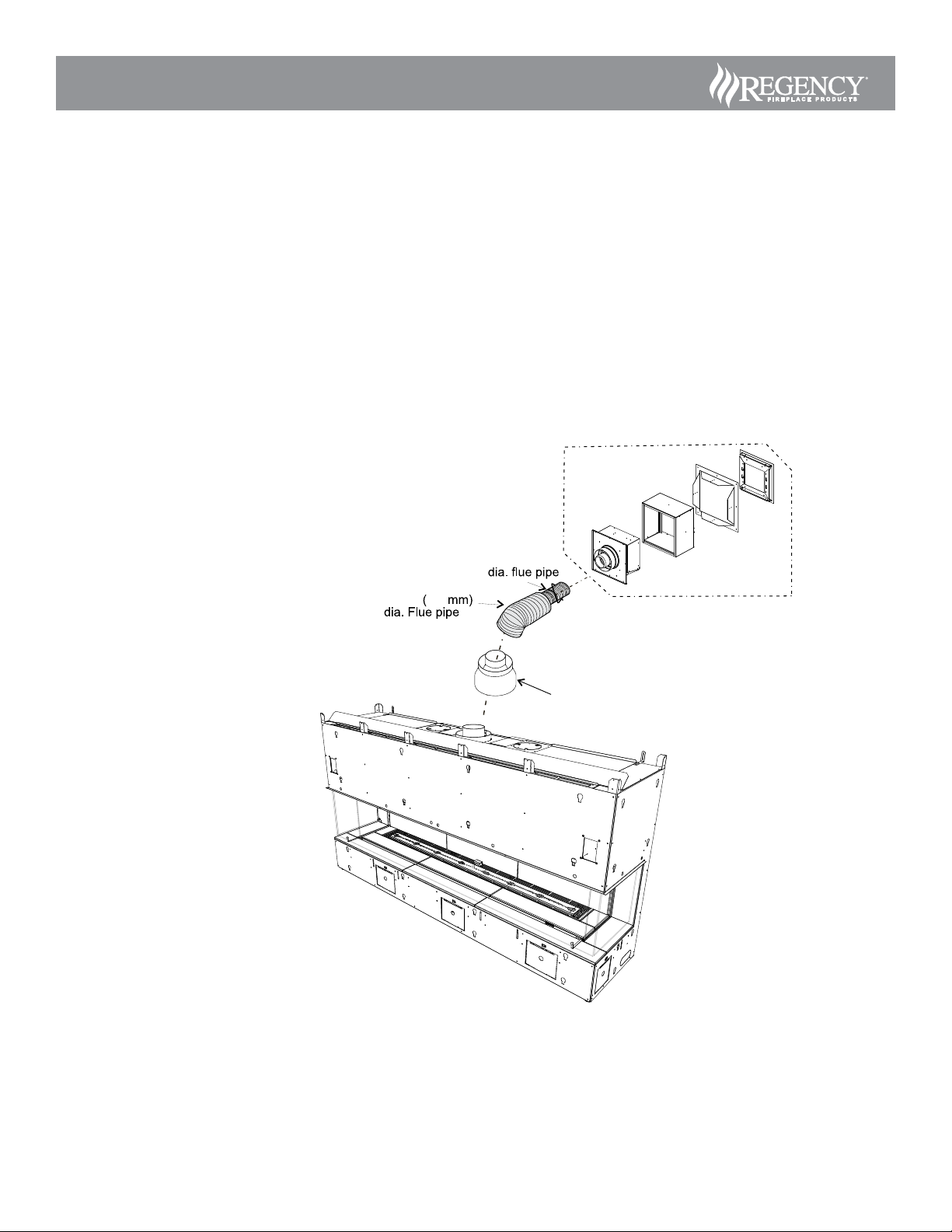
FLEX VENT 4" X 6-5/8"
These venting systems, in combination with the CB72EPV Direct Vent Gas Fireplace, has been tested and listed as a direct vent heater system by Intertek.
The location of the termination cap must conform to the requirements in the Vent Terminal Locations diagram in "Exterior Vent Termination Locations" section.
Regency
Notes:
1. Only Flex pipe purchased from Regency
2. Horizontal vent must be supported every 3 feet.
3. Regency
4. Flex system can only be used up to a maximum vent
5. Reducer (946-758) must be used in all applications when
®
Direct Vent (Flex) System Termination Kits include all the parts needed to install the CB72EPV using a exible vent.
®
may be used
for Flex installations
®
Direct Vent System (Flex) is only approved
for horizontal terminations.
length of up to 40 feet using up to 2 x 20 ft ex kits (Part
# 946-756). If longer runs are required, rigid pipe must
be used.
using ex venting.
4"
Powervent Kit
(Part #946-535)
6-5/8"
152
Vent reducer
(Part #946-758)
 Loading...