

Page 1
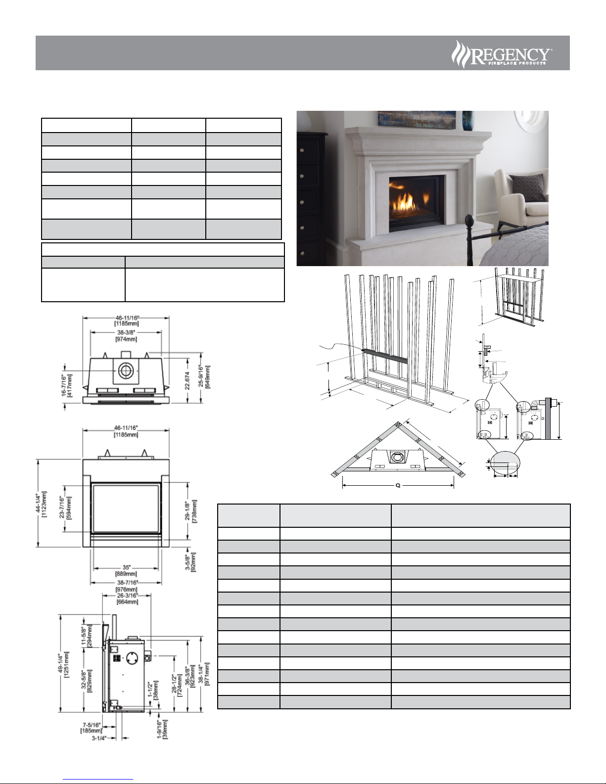
B41XTCE Gas Fireplace
Q
P
U
V
T
Openingfor gas
connection
11"(279mm)
dia. Hole through
wall Vent.
Non-Combustible
Header
(steel stud) on edge
Drywall
(orother
facing)
W
Non-CombustibleFacing
S
S
R
Non-combustible
Header
(steel stud
on edge)
M
N
L
O
Model B41XTCE-NG10 B41XTCE-LP10
Fuel Type Natural Gas Propane
Minimum Supply Pressure 5” W.C./C.E. (1.25 kPa) 11” W.C./C.E. (2.74 kPa)
Manifold Pressure - High 3.5” W.C./C.E. (0.87 kPa) 10” W.C./C.E. (2.49 kPa)
Manifold Pressure - Low 1.6” W.C./C.E. (0.40 kPa) 6.4” W.C./C.E. (1.60 kPa)
Orice Size -Altitude 0-4500 ft. #30 DMS #49 DMS
Minimum Input
Altitude 0-4500 ft. (0-1372m)
Maximum Input
Altitude 0-4500 ft. (0-1372m)
Approved Venting Systems
Flex Vent Systems: FPI AstroCap™ Flex Vent
Rigid Pipe Vent Systems: Simpson Direct Vent Pro®
30,000 BTU/h
(8.79 kW)
42,500 BTU/h
(12.45 kW)
Selkirk Direct-Temp™
Metal-Fab® Sure Seal
ICC Excel Direct Vent
29,500 BTU/h
(8.65 kW)
37,500 BTU/h
(10.99 kW)
Framing
Description B41XTCE
Dimensions
M Framing Width 47-1/4"(1200mm)
N Framing Height 49-1/2" (1257mm)
O (Rear Vent) Framing Depth - Rear Vent 26-1/2" (673mm)
O (Top Vent) Framing Depth - Top Vent 25-7/8" (657mm)
P Corner Facing Wall Width 65-1/4" (1657mm)
Q Corner Facing Wall Width 91-11/16" (2329mm)
R (Rear Vent) Framed Chase Ceiling - Rear 49-1/2" (1257mm)
R (Top Vent) Framed Chase Ceiling - Top 54-1/2" (1384mm)
S (Rear Vent) Vent Centerline Height - Rear 28-1/2" (724mm)
S (Top Vent) Vent Centerline Height - Top 47-1/2" (1207mm) Rigid / Flex
T Gas Connection Height 1-1/2" (38mm)
U Gas Connection Inset 5" (127mm)
V Gas Connection Width 3-1/4" (82mm)
W Non-Combustible Top Height 13-1/2" (343mm)
** Important: Framing height requires consideration of the hearth depth.
Dimension N = N + the thickness of the installed hearth.
Page 2
B41XTCE Gas Fireplace
C
Close to Ceiling
F
E
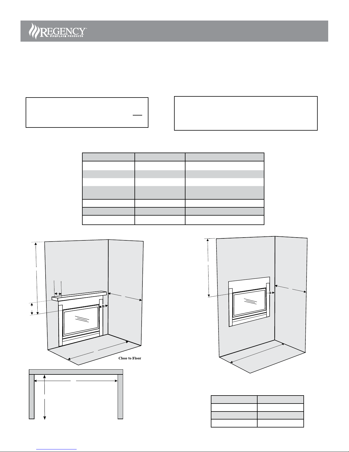
CLEARANCES
The clearances listed below are Minimum distances unless otherwise stated:
A major cause of chimney related res is failure to maintain required clearances (air space) to combustible materials. It is of the greatest
importance that this replace and vent system be installed only in accordance with these instructions.
The top, back and sides of the fireplace are defined by
Caution Requirements
standoffs. The metal ends of the standoff may NOT
be recessed into combustible construction.
B41 XTCE Clearance Requirements
Clearance: Dimension Measured From:
A: Mantel Height (min.) 17-9/16" (446mm) Top of Fireplace Opening
B: Sidewall 9" (229mm) Side of Fireplace Opening
C: Ceiling 36-5/8" (930mm) Top of Fireplace Opening
D: Mantel Depth (max.) 12" (304mm) 25-13/16" (651mm)
E: Alcove Width 60" (1524mm) Wall to Wall (Minimum)
F: Alcove Depth 36" (914mm) Front to Back Wall (Maximum)
Notes: 0" No Hearth Required
Fire hazard is an extreme risk
WARNING
if these clearances (air space) to combustible materials are not
adhered to. It is of greatest importance that this replace and vent
system be installed only in accordance with these instructions.
from Top of Fireplace Opening
C
D
A
E
E
F
Alcove
F
Minimum Vent Clearances
to Combustibles
Horizontal Top 3" (76mm)
Horizontal Side 2 " (51mm)
Horizontal Bottom 2" (51mm)
Vertical Vent 2" (51mm)
Page 3
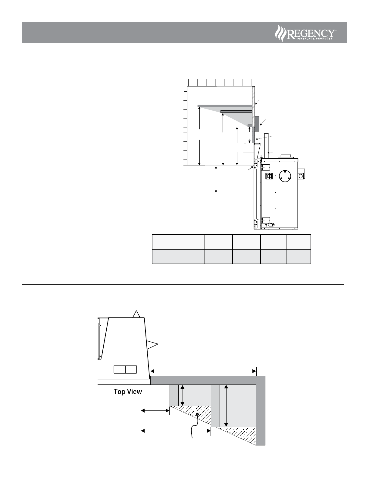
MANTEL CLEARANCES
Mantel Clearances
projection.
B41XTCE Gas Fireplace
Due to the extreme heat this replace emits, the
mantel clearances are critical. Combustible mantel
clearances from top of front facing are shown in the
diagram on the right.
Note: A non-combustible mantel may be
installed at a lower height if the framing
is made of metal studs covered with a
non-combustible board.
Note: Ensure the paint that is used on the mantel
and the facing is "heat resistant" or the
paint may discolour.
12
14
24
12
Inches
B
0
To Floor
Mantel Clearances
B41XTCE
From Top of
Fireplace Opening
2
0
Combustible
1"
6
64810
12
7
C
D
Top of
A
32-11/16"
(830mm)
Fireplace
Opening
A B C D
25-13/16"
(656mm)
Non-combustible
Header
(steel stud)
on edge
Non-combustible
Standoff
22-1/16"
(560mm)
17-9/16"
(446mm)
MANTEL LEG CLEARANCES
9 Side Wall
(Measured from side of
Fireplace Opening)
Mantel leg
1-1/2"
4
7
Allowable mantel leg
Mantel leg
3"
Page 4
B41XTCE Gas Fireplace
Combustible
Material
Non-combustible
Finishing Materia
l(ie. tile)
Non-combustible Material (6" x 46-11/16")
Finishing Material
(ie. tile)
Nailing Strip
-1/2" back from unit face
Combustible
Material
Non-combustible
Supplied with Unit
1-1/2
(38mm)
Ensure finished
material is
brought to lip
Combustible
Material
Non-combustible
Finishing Material
Non-combustible Material (6" x 46-11/16")
Finishing Material
Nailing Strip
-flush with unit face
Combustible
Material
Non-combustible
Supplied with Unit
1-1/2
(38mm)
Ensure finished
material is
brought to lip
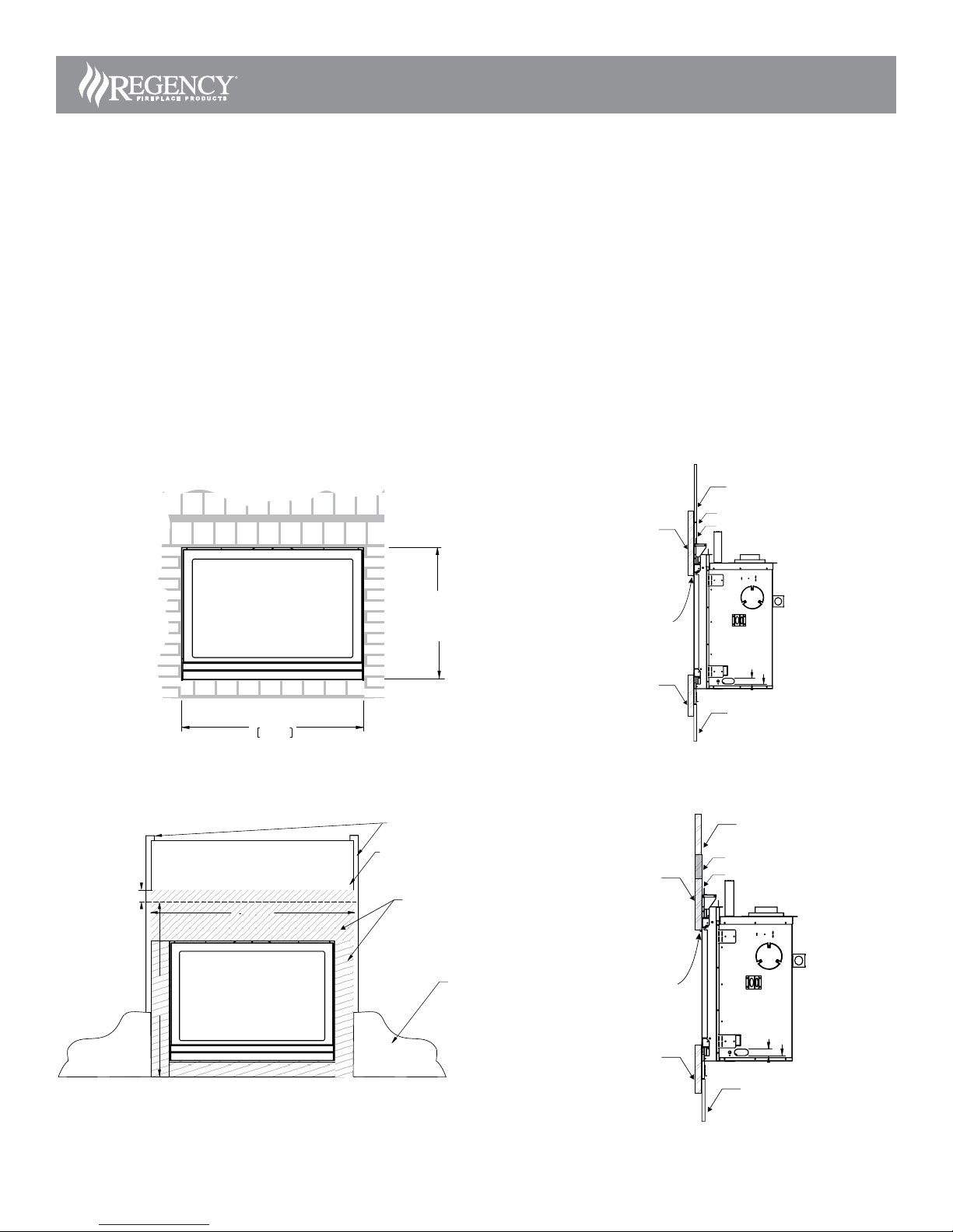
FRAMING & FINISHING
1. Frame in the enclosure for the unit with framing material.
Note: When constructing the framed opening, please ensure there is access to install the gas lines when the unit is installed.
2. For exterior walls, insulate the enclosure to the same degree as the rest of the house; apply vapour barrier and drywall, as per local installation codes.
(Do not insulate the replace itself.)
WARNING: Failure to insulate and add vapor barriers to the inside of the exterior wall will result in operational and performance problems
including, but not limited to: excessive condensation on glass doors, poor ame package, carbon, blue ames etc. These are not product
related issues.
3. The unit does not have to be completely enclosed in a chase. You must maintain clearances from the vent to combustible materials: See "Clearances"
section. Combustible materials can be laid against the side and back standoffs and the stove base.
4. Tile Finish Option 1: Drywall may be installed onto the unit as shown below to create a surface to apply finishing materials such as tile, slate, etc.
Drywall cannot extend beyond the metal surface of the unit.
5. Tile Finish Option 2: If applying a non-combustible finishing material (tile,slate,etc) the material can be installed directly onto the metal surface (clean
front) of the unit in the area shown below.
TILE FINISH
6. If applying a non-combustible facing it may be installed over the metal surface (clean front) of the unit in the area shown below.
CLEAN FINISH
6"
[152mm]
NON COMBUSTIBLE BOARD SUPPLIED W/UNIT
44-1/4"
[1124mm]
38-7/16"
976mm
46-11/16"
[1186mm]
[737mm]
29"
WOOD STUD
1/2" DRYWALL
DO NOT EXTEND
DRYWALL ONTO METAL
SURFACE OF UNIT.
NON-COMBUSTIBLE FACING
FOR CLEAN LOOK (ie. painted finish)
(SUPPLIED BY OTHERS)
1/2" DRYWALL
NOTE: The 6" x 46-11/16" non combustible material supplied with this unit can be replaced if trying to achieve a clean finish. A large piece of non
Combustible and Non-combustible Facing and
Finishing Materials around unit.
combustible material (ie. 4' x 8' x 1/2" can be used to eliminate taped seams on or near unit.
Page 5
B41XTCE Gas Fireplace
32-7/8"
835mm
25-5/8"
[651mm]
NO FACING OR
FINISHING MATERIAL
IN THIS AREA
No Combustible
Materials in this Area
41-5/8"
[1057mm]
40-5/8"
[1031mm]
4-1/8"
[105mm]
8-3/8"
[213mm]
3-7/8"
[98mm]
3-1/2"
[89mm]
Non combustible - supplied w/unit
J Style trim or metal
corner bead may be
used to finish edges
No Combustible
Materials in this Area
29"
[737mm]
38-7/16"
976mm
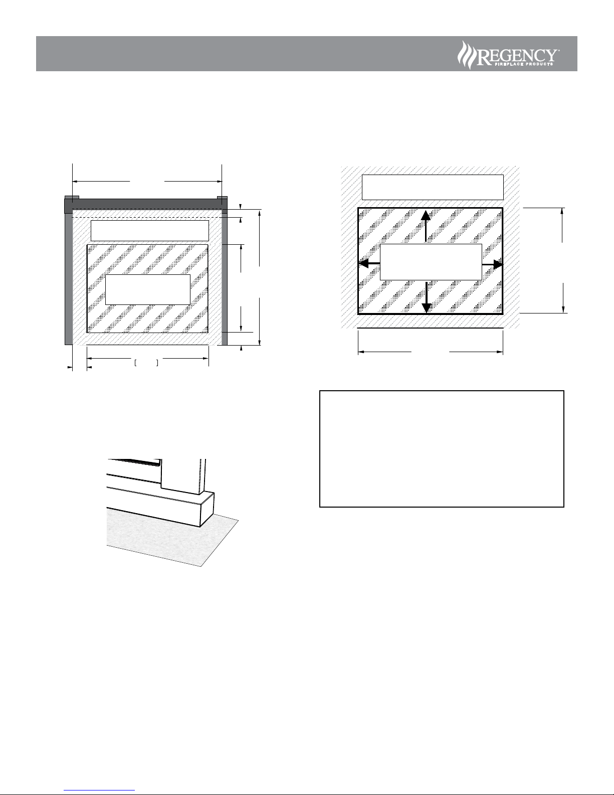
7. Non-combustible material (ie. tile, slate, etc) may be brought up to the edge of the glass door of the unit. Minimum clearances must be adhered to, this
will assure ease of glass door removal and access to the lower panel.
NOTE: Non-combustible finishing materials may be of any thickness desired.
Minimum Clearances for Finishing Materials
IMPORTANT FINISHING DETAIL NOTE:
Before placing unit into nal position - it is important to know the total
thickness / height of nished hearth (tile, carpet, etc.) The base of the
replace, 4 sided faceplate or mantel should be level or higher than the
nished hearth height.
Trim materials
Note: All non-combustible facing material should butt up cleanly
to the flanges around the firebox opening.
Rough edges may be visible from an angle.
To maintain a clean finished edge - facing material edges
may be finished with a J-style trim or metal cornerbead (both
materials available at your local building or hardware store).
IMPORTANT: Materials used must be NON-COMBUSTIBLE.
Page 6
B41XTCE Gas Fireplace
Vertical Height (Feet)
47-1/2"
Horizontal (Feet)
Vertical Height (Feet)
1/2"(0.7m)
Horizontal (Feet)
Rear Venting
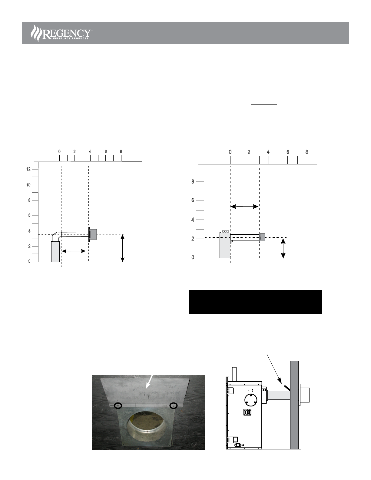
VENTING ARRANGEMENTS FOR HORIZONTAL TERMINATIONS
The diagrams show all allowable combinations of vent runs with 5" x 8" venting using the Regency direct vent system or rigid vent system.
A vent guard should be used whenever the termination is lower than the specied minimum or as per local codes.
For horizontal terminations the Regency Direct Vent Flex System may be used for installations upto a maximum continuous vent length of 10ft (3.0m).
Note: Must use optional rigid pipe adaptor (Part # 770-994) when using Rigid Pipe vent systems.
• Maintain clearance to combustibles.
• Horizontal vent must be supported every 3 feet.
• Firestops are required at each oor level and whenever passing through a wall.
12
10
0
2
8
6
4
8
0
2
4
6
8
8
6
Max. 36"(0.9m)
FLEX VENT OR RIGID PIPE 5" X 8"
6
4
(1.2m)
2
0
Max. 36(0.9m)
Rigid or Flex
4
2
0
28 -
Vent Restrictor - Set 1
REAR VENTING DEFLECTOR INSTALLATION
FOR REAR VENTED HORIZONTAL TERMINATIONS
The Rear Vent Deector comes with the unit. When the unit is shipped
the deector is slightly tucked underneath the top nailing strips located
at the top of the rebox.
NOTE: The Rear Venting Deector must be installed before the unit is
put in place.
1) Secure the rear venting
deector to the wall thimble
using 2 screws as shown.
Ensure to use the same screw
holes as the wall thimble.
Rear Venting Deector
Factory Setting - No Restrictor Required
IMPORTANT
Must use Rear Venting Deector packaged with unit in
rear vent horizontal termination applications.
Deflector
Page 7
Vertical Height (Feet)
VENTING ARRANGEMENTS
Minimum
8 (2.4m)
Min. 47-1/2
(1.2m)
0
2
4
6
40
8
10
12
14
16
18
20
22
24
26
28
30
Vertical Height (Feet)
32
34
36
38
6
8
Horizontal (Feet)
2
0
4 10
12
Restrictor 1-1/2 Open
Maximum 10 Centerline to Centerline
Restrictor 2-1/2 Open
Maximum 8 Centerline to Centerline
Restrictor 3-1/2 Open
Set 2
Set 3
Set 1
FOR HORIZONTAL TERMINATIONS
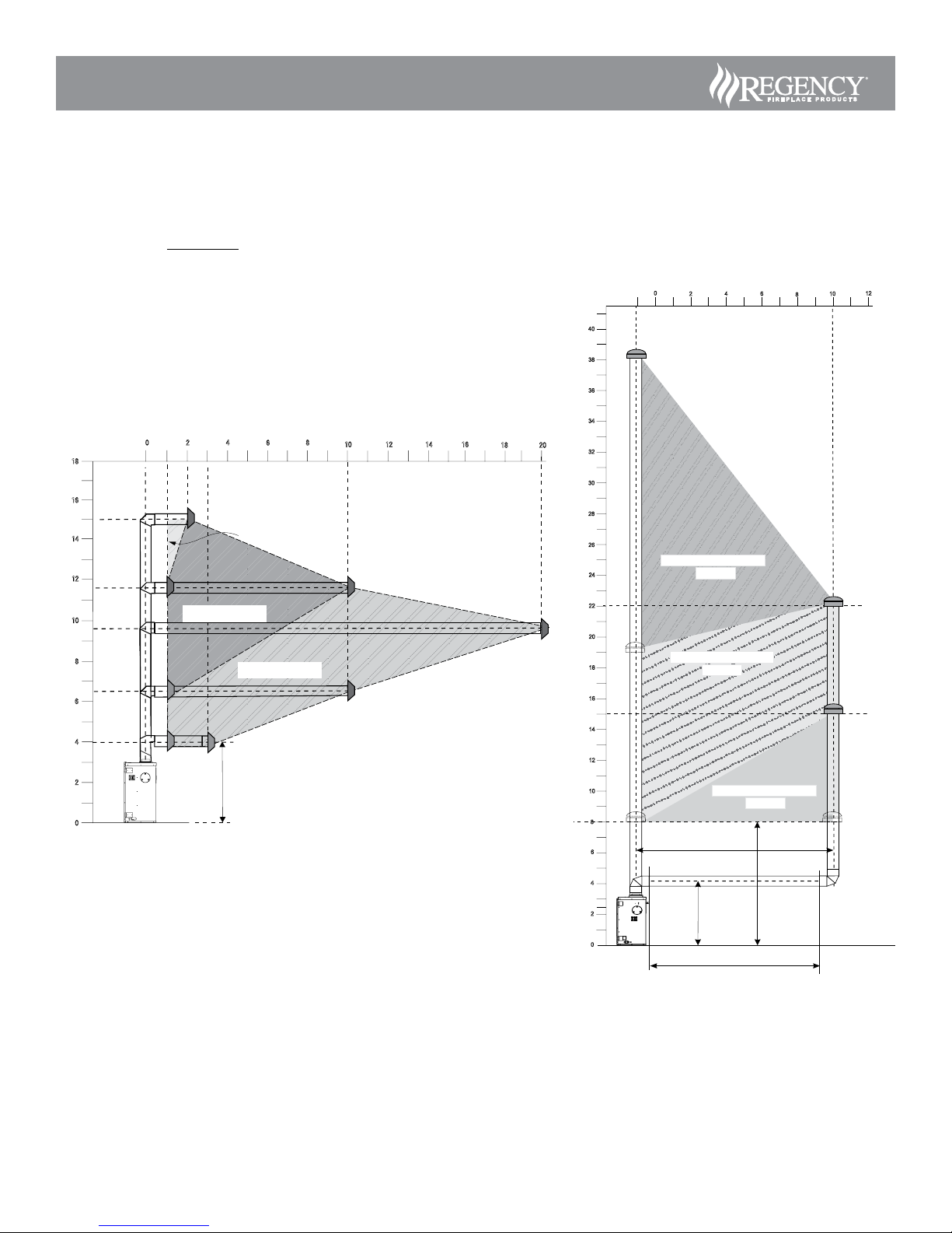
The diagram shows all allowable combinations of vertical runs with horizontal
terminations, using one 90o (two 45o elbows equal one 90o elbow).
• Maintain clearances to combustibles as listed in "Clearances" section
• Horizontal vent must be supported every 3 feet.
• Firestops are required at each oor level and whenever passing through
a wall.
• A wall thimble is mandatory for all horizontal terminations due to high
temperatures.
B41XTCE Gas Fireplace
VENTING ARRANGEMENTS
FOR VERTICAL TERMINATIONS
The shaded area in the diagram shows all allowable combinations of straight
vertical and oset to vertical terminations, using two 90o elbows, with Rigid
Pipe Venting Systems for Propane and Natural Gas. Two 45
equal to one 90o elbow. Maximum of four 45o elbows allowed.
o
elbows
0
18
16
Restrictor 1-1/2 Open
14
12
10
8
6
4
2
0
Restrictor 2-1/2 Open
Set 2
Restrictor 3-1/2 Open
47-1/2"
(1207mm)
Minimum
Height
Requirement
Set 3
6
Set 1
8
12
10 14 16
18 20
4
Horizontal (Feet)
2
• Vent must be supported at osets.
• Firestops are required at each oor level and whenever
passing through a wall.
• Maintain clearances to combustibles as listed in the
"Clearances" section.
• Refer to the "Vent Restrictor Position" section for
details on how to change the vent restrictor from the
factory setting to 2-1/4" opening ,1-5/8"opening and
to 1-1/16" opening.
Note: Must use optional ue adapter when using Rigid
Pipe (Part # 770-994..
 Loading...