

Page 1
R E G E N C Y
Model 4720 Control/Communicator
Installation Manual
Part Number 150476, Rev. A
Initial Release Date: March 1995
Revised October 1998
Page 2

Interactive Technologies, Inc.
226 6 Second Street N orth
North Saint Paul, M N 55109-2900
T: 651/777-2690
F: 651/779-4890
OETHCN SGOLIE
Security
Automation
Fire Protection
Access Control
Visit our website at www.ititechnologies.com
ITI and Regency are registered trademarks of Interactive Technologies, Inc.
ITI © 1998. All rights reserved.
For reprints, order manual: 150476, Revision A
Page 3

Regency® Model 4720 Control/Communicator Installation Manual (P/N 150476, Rev. A) Revised 10/98
Notices
FCC Part 15 Information to the User
Changes or modifications not expressly approved by Interact ive Technologies, Inc. can void the user’s authority to operate the equipment.
FCC Part 15 Class B
This equipment has been tested and found to comply with the limits for a Class B digital device, pursuant to
part 15 of the FCC Rules. These limits are designed to provide reasonable protection against interference in a
residential installation.
This equipment generates, uses, and can radiate radio frequency energy and, if not installed and use d in
accordance with the instructions, may cause harmful interfer ence to radio comm unica tions . How ever, there is
no guarantee that interference will not occur in a particular installation.
If this equipment does cause harmful interference to radio or television reception, which can be determined by
turning the equipment off and on, the user is encouraged to try the correct the interference by one or more of
the following measures:
■ Reorient or relocate the panel’s receiving antenna.
■ Increase the separation between the equipment and receiver.
■ Connect the affected equipment and the panel receiver to separate outlets, on different branch cir-
cuits.
■ Consult the dealer or an experienced radio/TV technician for help.
FCC Part 68
This equipment complies with part 68 of the FCC Rules. Located on this equipment is a label that contains,
among other information, the FCC registration number and the ringer equivalence numbe r (RE N) for this
equipment. If requested, this information must be provided to the telephone comp any.
The REN is used to determine the maximum number of devices that may be connected to your telephone l ine.
In most areas, the sum of all device RENs should not exceed five (5.0).
If this equipment causes harm to the telephone network, the telephone company may temporarily disconnect
your service. If possible, you will be notified in advance. When advance notice is not pra ct ical, yo u will be notified as soon as possible. You will also be advised of your right to file a complaint with the FCC.
Your telephone company may make changes in its facilities, equipment, operations, or procedures that could
affect the proper operation of your equipment. You will be given advance notice in order to maintain uninterrupted service.
If you experience trouble with this equipment, please contact the company that installed the equipment for service and repair information. The telephone company may ask you to disconnect this equipment from the network until the problem has been corrected or you are sure that the equipment is not malfunctioning.
This equipment may not be used on coin service provided by the telephone company . Connection to party lines
is subject to state tariffs.
i
Page 4

Regency® Model 4720 Control/Communicator Installation Manual (P/N 150476, Rev. A) Revised 10/98
Table of Contents
1 Introduction . . . . . . . . . . . . . . . . . . . . . . . . . . . . . . . . . . . . . . . . . . . . . . . . . . . . . . . . . . . . 1
1.1 Features . . . . . . . . . . . . . . . . . . . . . . . . . . . . . . . . . . . . . . . . . . . . . . . . . . . . . . . . . . . . . . . . . . 1
1.2 Accessories . . . . . . . . . . . . . . . . . . . . . . . . . . . . . . . . . . . . . . . . . . . . . . . . . . . . . . . . . . . . . . . 1
2 Preconnection Requirements . . . . . . . . . . . . . . . . . . . . . . . . . . . . . . . . . . . . . . . . . . . . . 2
2.1 Telephone Requirements . . . . . . . . . . . . . . . . . . . . . . . . . . . . . . . . . . . . . . . . . . . . . . . . . . . . . 2
2.2 FCC Requirements . . . . . . . . . . . . . . . . . . . . . . . . . . . . . . . . . . . . . . . . . . . . . . . . . . . . . . . . . 3
2.3 UL Installation Requirements . . . . . . . . . . . . . . . . . . . . . . . . . . . . . . . . . . . . . . . . . . . . . . . . . 3
2.3.1 Hardware. . . . . . . . . . . . . . . . . . . . . . . . . . . . . . . . . . . . . . . . . . . . . . . . . . . . . . . . . . . . 3
2.3.1.1 Hardware Requirements . . . . . . . . . . . . . . . . . . . . . . . . . . . . . . . . . . . . . . . . . . 3
2.3.1.1 Hardware Restrictions. . . . . . . . . . . . . . . . . . . . . . . . . . . . . . . . . . . . . . . . . . . . 3
2.3.1 Programming Options. . . . . . . . . . . . . . . . . . . . . . . . . . . . . . . . . . . . . . . . . . . . . . . . . . 3
2.3.1.1 Programming Requirements . . . . . . . . . . . . . . . . . . . . . . . . . . . . . . . . . . . . . . . 3
2.3.1.1 Programming Restriction s. . . . . . . . . . . . . . . . . . . . . . . . . . . . . . . . . . . . . . . . . 4
2.3.1 NFPA 72 Temporal Pattern Siren Local Protective Signaling Systems (UL 864) and
Household Fire Warning Systems (UL 985) 4
2.3.1 NFPA 72 Central Station Signaling and Local Protective Signaling Systems (UL 864) 5
2.3.1.1 NFPA 72 Central Station Signaling Systems (Formerly NFPA 71). . . . . . . . . 5
2.3.1.1 NFPA 72 Local Protective Signaling Systems . . . . . . . . . . . . . . . . . . . . . . . . . 5
2.3.1 Grade A Mercantile Requirements (UL 365). . . . . . . . . . . . . . . . . . . . . . . . . . . . . . . . 5
2.3.1 Fire System Test Procedure for UL 985 Systems. . . . . . . . . . . . . . . . . . . . . . . . . . . . . 7
3 Control Panel Description . . . . . . . . . . . . . . . . . . . . . . . . . . . . . . . . . . . . . . . . . . . . . . . . 7
3.1 Battery Cables . . . . . . . . . . . . . . . . . . . . . . . . . . . . . . . . . . . . . . . . . . . . . . . . . . . . . . . . . . . . 10
3.2 DC Power Switch . . . . . . . . . . . . . . . . . . . . . . . . . . . . . . . . . . . . . . . . . . . . . . . . . . . . . . . . . 10
3.3 Overcurrent Protection . . . . . . . . . . . . . . . . . . . . . . . . . . . . . . . . . . . . . . . . . . . . . . . . . . . . . 10
3.3.1 PolySwitch® Circuit Protectors . . . . . . . . . . . . . . . . . . . . . . . . . . . . . . . . . . . . . . . . . 10
3.3.1 Fuses. . . . . . . . . . . . . . . . . . . . . . . . . . . . . . . . . . . . . . . . . . . . . . . . . . . . . . . . . . . . . . 11
3.4 LEDs . . . . . . . . . . . . . . . . . . . . . . . . . . . . . . . . . . . . . . . . . . . . . . . . . . . . . . . . . . . . . . . . . . . 11
3.5 Earth Grounding Wire . . . . . . . . . . . . . . . . . . . . . . . . . . . . . . . . . . . . . . . . . . . . . . . . . . . . . . 11
3.6 AC Power Light . . . . . . . . . . . . . . . . . . . . . . . . . . . . . . . . . . . . . . . . . . . . . . . . . . . . . . . . . . 12
3.7 Touchpad Volume Control . . . . . . . . . . . . . . . . . . . . . . . . . . . . . . . . . . . . . . . . . . . . . . . . . . . 12
3.8 Charging Voltage Adjustment (Factory Set) . . . . . . . . . . . . . . . . . . . . . . . . . . . . . . . . . . . . . 12
3.9 Clock Speed Adjustment (Factory Set) . . . . . . . . . . . . . . . . . . . . . . . . . . . . . . . . . . . . . . . . . 12
3.10 Cable Connectors . . . . . . . . . . . . . . . . . . . . . . . . . . . . . . . . . . . . . . . . . . . . . . . . . . . . . . . . . 12
3.10.1 Model 4660C Series Touchpad Connector—Troubleshooting (P1) . . . . . . . . . . . . . 12
3.10.1 Status Connector (P2). . . . . . . . . . . . . . . . . . . . . . . . . . . . . . . . . . . . . . . . . . . . . . . . . 12
3.10.1 Phone Line Monitor Connector (P5) . . . . . . . . . . . . . . . . . . . . . . . . . . . . . . . . . . . . . 12
3.10.1 Intercom Module Connector (P6). . . . . . . . . . . . . . . . . . . . . . . . . . . . . . . . . . . . . . . . 12
3.11 Expansion Connectors (P3 and P4) . . . . . . . . . . . . . . . . . . . . . . . . . . . . . . . . . . . . . . . . . . . . 12
ii
Page 5

Regency® Model 4720 Control/Communicator Installation Manual (P/N 150476, Rev. A) Revised 10/98
3.12 Jumper Blocks and Jumper Wires . . . . . . . . . . . . . . . . . . . . . . . . . . . . . . . . . . . . . . . . . . . . .14
3.12.1 Jumper Block J1 . . . . . . . . . . . . . . . . . . . . . . . . . . . . . . . . . . . . . . . . . . . . . . . . . . . . 14
3.12.1 Jumper Block J2 . . . . . . . . . . . . . . . . . . . . . . . . . . . . . . . . . . . . . . . . . . . . . . . . . . . . 14
3.12.1 Jumpers J3 and J4 . . . . . . . . . . . . . . . . . . . . . . . . . . . . . . . . . . . . . . . . . . . . . . . . . . . 14
3.12.1 Jumper Blocks J5 and J6 (Starting with Revision L PC Board) . . . . . . . . . . . . . . . . 14
3.13 Plug-On Terminal Strips . . . . . . . . . . . . . . . . . . . . . . . . . . . . . . . . . . . . . . . . . . . . . . . . . . . .15
3.13.1 Terminal Strip Removal. . . . . . . . . . . . . . . . . . . . . . . . . . . . . . . . . . . . . . . . . . . . . . . 15
3.13.1 Terminal Strip Replacement . . . . . . . . . . . . . . . . . . . . . . . . . . . . . . . . . . . . . . . . . . . 15
3.14 Model 4720 Terminal Strip Description . . . . . . . . . . . . . . . . . . . . . . . . . . . . . . . . . . . . . . . . 16
3.15 Non-UL Wiring Diagram . . . . . . . . . . . . . . . . . . . . . . . . . . . . . . . . . . . . . . . . . . . . . . . . . . . .17
4 4720 Control Panel Overview . . . . . . . . . . . . . . . . . . . . . . . . . . . . . . . . . . . . . . . . . . . . .18
4.1 Current Draw Calculations . . . . . . . . . . . . . . . . . . . . . . . . . . . . . . . . . . . . . . . . . . . . . . . . . . .18
4.1.1 Total Standby and Alarm Current Draw . . . . . . . . . . . . . . . . . . . . . . . . . . . . . . . . . . 18
4.1.1 Current Draw on Protective Devices Indicated by LEDs 2 and 3 (F2 and F3). . . . . 21
4.2 System Planning Block Diagram . . . . . . . . . . . . . . . . . . . . . . . . . . . . . . . . . . . . . . . . . . . . . . 23
5 Wiring Precautions . . . . . . . . . . . . . . . . . . . . . . . . . . . . . . . . . . . . . . . . . . . . . . . . . . . . .24
6 Model 4720 Control Panel Installation . . . . . . . . . . . . . . . . . . . . . . . . . . . . . . . . . . . . . .24
6.1 Selecting a Location . . . . . . . . . . . . . . . . . . . . . . . . . . . . . . . . . . . . . . . . . . . . . . . . . . . . . . . . 24
6.2 Mounting the Model 4720 . . . . . . . . . . . . . . . . . . . . . . . . . . . . . . . . . . . . . . . . . . . . . . . . . . .25
6.3 Installing the Model 9220 Power Transformer . . . . . . . . . . . . . . . . . . . . . . . . . . . . . . . . . . .25
6.3.1 Model 4165 Transformer Housing . . . . . . . . . . . . . . . . . . . . . . . . . . . . . . . . . . . . . . 25
6.3.1 Installing the Transformer. . . . . . . . . . . . . . . . . . . . . . . . . . . . . . . . . . . . . . . . . . . . . 26
6.4 Model 4195 Auxiliary Power Supply . . . . . . . . . . . . . . . . . . . . . . . . . . . . . . . . . . . . . . . . . .27
7 Touchpad Installation . . . . . . . . . . . . . . . . . . . . . . . . . . . . . . . . . . . . . . . . . . . . . . . . . . .28
7.1 Mounting the Touchpads . . . . . . . . . . . . . . . . . . . . . . . . . . . . . . . . . . . . . . . . . . . . . . . . . . . . 28
7.2 Wiring the Touchpads . . . . . . . . . . . . . . . . . . . . . . . . . . . . . . . . . . . . . . . . . . . . . . . . . . . . . .29
7.3 Daisy-Chaining Touchpads . . . . . . . . . . . . . . . . . . . . . . . . . . . . . . . . . . . . . . . . . . . . . . . . . .29
7.4 Setting ID Codes . . . . . . . . . . . . . . . . . . . . . . . . . . . . . . . . . . . . . . . . . . . . . . . . . . . . . . . . . .30
7.5 Model 4203 Weather-Resistant, SlimLine Touchpad . . . . . . . . . . . . . . . . . . . . . . . . . . . . . . . 30
7.5.1 Mounting the Model 4203. . . . . . . . . . . . . . . . . . . . . . . . . . . . . . . . . . . . . . . . . . . . . 30
7.5.1 Wiring the Model 4203 . . . . . . . . . . . . . . . . . . . . . . . . . . . . . . . . . . . . . . . . . . . . . . . 30
7.6 Mechanical Keyswitch . . . . . . . . . . . . . . . . . . . . . . . . . . . . . . . . . . . . . . . . . . . . . . . . . . . . . .31
8 Powering Up the System . . . . . . . . . . . . . . . . . . . . . . . . . . . . . . . . . . . . . . . . . . . . . . . . .31
9 Internal Zones . . . . . . . . . . . . . . . . . . . . . . . . . . . . . . . . . . . . . . . . . . . . . . . . . . . . . . . . . .31
9.1 Normally Open and Normally Closed Contact Wiring . . . . . . . . . . . . . . . . . . . . . . . . . . . . .32
9.2 Smoke Detector Wiring . . . . . . . . . . . . . . . . . . . . . . . . . . . . . . . . . . . . . . . . . . . . . . . . . . . . .32
9.3 Model 7181 Fire Zone Converter . . . . . . . . . . . . . . . . . . . . . . . . . . . . . . . . . . . . . . . . . . . . . .33
10 Local Annunciation . . . . . . . . . . . . . . . . . . . . . . . . . . . . . . . . . . . . . . . . . . . . . . . . . . . . .33
10.1 Fire Bell Wiring with the Model 4160 Supervised Bell Module . . . . . . . . . . . . . . . . . . . . . .33
10.1.1 Auxiliary Power for Supervised Bells. . . . . . . . . . . . . . . . . . . . . . . . . . . . . . . . . . . . 34
10.2 Commercial Burglary Bell Wiring . . . . . . . . . . . . . . . . . . . . . . . . . . . . . . . . . . . . . . . . . . . . .35
10.3 External Speaker Wiring . . . . . . . . . . . . . . . . . . . . . . . . . . . . . . . . . . . . . . . . . . . . . . . . . . . .36
iii
Page 6

Regency® Model 4720 Control/Communicator Installation Manual (P/N 150476, Rev. A) Revised 10/98
10.4 Internal Speaker Wiring . . . . . . . . . . . . . . . . . . . . . . . . . . . . . . . . . . . . . . . . . . . . . . . . . . . . 37
10.5 Model 4180 Status Relays . . . . . . . . . . . . . . . . . . . . . . . . . . . . . . . . . . . . . . . . . . . . . . . . . . . 37
11 Telephone Line Connection . . . . . . . . . . . . . . . . . . . . . . . . . . . . . . . . . . . . . . . . . . . . . . 38
11.1 Line 1 Wiring . . . . . . . . . . . . . . . . . . . . . . . . . . . . . . . . . . . . . . . . . . . . . . . . . . . . . . . . . . . . 38
11.2 Ground Start Relay Wiring . . . . . . . . . . . . . . . . . . . . . . . . . . . . . . . . . . . . . . . . . . . . . . . . . . 38
11.3 External Dialer Failed Indicator . . . . . . . . . . . . . . . . . . . . . . . . . . . . . . . . . . . . . . . . . . . . . . 39
11.4 Model 4175 Dual Phone Line Monitor with Ring Detector . . . . . . . . . . . . . . . . . . . . . . . . . 39
11.4.1 Model 4175 Wiring . . . . . . . . . . . . . . . . . . . . . . . . . . . . . . . . . . . . . . . . . . . . . . . . . . . 39
11.4.1 Model 4175 Operation . . . . . . . . . . . . . . . . . . . . . . . . . . . . . . . . . . . . . . . . . . . . . . . . 40
12 Expansion Zones . . . . . . . . . . . . . . . . . . . . . . . . . . . . . . . . . . . . . . . . . . . . . . . . . . . . . . 40
12.1 Model 4110 Zone Expander . . . . . . . . . . . . . . . . . . . . . . . . . . . . . . . . . . . . . . . . . . . . . . . . . 40
12.1.1 Connecting the SmartSensors. . . . . . . . . . . . . . . . . . . . . . . . . . . . . . . . . . . . . . . . . . . 40
12.1.1 Determining ID Numbers and Zone Numbers . . . . . . . . . . . . . . . . . . . . . . . . . . . . . . 43
12.1.1.1 Calculating 4110 ID Numbers from Zone Numbers. . . . . . . . . . . . . . . . . . . . 43
12.1.1.1 Calculating Zone Numbers from ID Numbers . . . . . . . . . . . . . . . . . . . . . . . . 43
12.1.1 Using Two Zone Expanders . . . . . . . . . . . . . . . . . . . . . . . . . . . . . . . . . . . . . . . . . . . . 43
12.2 Model 4115 Serial Zone Expander . . . . . . . . . . . . . . . . . . . . . . . . . . . . . . . . . . . . . . . . . . . . 44
12.3 Model 4125 Zone Expander . . . . . . . . . . . . . . . . . . . . . . . . . . . . . . . . . . . . . . . . . . . . . . . . . 44
12.3.1 Model 4125 Zone Wiring . . . . . . . . . . . . . . . . . . . . . . . . . . . . . . . . . . . . . . . . . . . . . . 44
12.3.1 Determining 4125 Zone Expander's Input and Zone Numbers . . . . . . . . . . . . . . . . . 46
12.3.1.1 Calculating 4125 Input and Zone Numbers . . . . . . . . . . . . . . . . . . . . . . . . . . 46
12.3.1.1 Calculating 4125 Zone and Input Numbers . . . . . . . . . . . . . . . . . . . . . . . . . . 46
12.3.1 Using Two Zone Expanders . . . . . . . . . . . . . . . . . . . . . . . . . . . . . . . . . . . . . . . . . . . . 46
12.4 Model 4130 Zone Expander . . . . . . . . . . . . . . . . . . . . . . . . . . . . . . . . . . . . . . . . . . . . . . . . . 46
12.4.1 Installing the Model 4130. . . . . . . . . . . . . . . . . . . . . . . . . . . . . . . . . . . . . . . . . . . . . . 46
12.4.1 Programming the Transmitters . . . . . . . . . . . . . . . . . . . . . . . . . . . . . . . . . . . . . . . . . . 47
13 Model 4184 Watchdog Module . . . . . . . . . . . . . . . . . . . . . . . . . . . . . . . . . . . . . . . . . . . 47
13.1 Model 4184 Watchdog Module Wiring . . . . . . . . . . . . . . . . . . . . . . . . . . . . . . . . . . . . . . . . . 47
13.2 Operating Procedure, 4184 Watchdog Module . . . . . . . . . . . . . . . . . . . . . . . . . . . . . . . . . . . 48
14 Other Expansion Devices . . . . . . . . . . . . . . . . . . . . . . . . . . . . . . . . . . . . . . . . . . . . . . . 48
14.1 Model 4140 Intercom/Telephone Controller . . . . . . . . . . . . . . . . . . . . . . . . . . . . . . . . . . . . . 48
14.1.1 Mounting the Model 4640 . . . . . . . . . . . . . . . . . . . . . . . . . . . . . . . . . . . . . . . . . . . . . 49
14.1.1 Mounting the Model 4640 as a Stand-Alone Intercom . . . . . . . . . . . . . . . . . . . . . . . 50
14.1.1 Connecting the Model 4140 to the Model 4640 Intercom Station . . . . . . . . . . . . . . . 50
14.1.1 7381 Connecting the Model 4140 to the Model 7381 Front Door Intercom Station . 52
14.2 Model 4150 Environment Control . . . . . . . . . . . . . . . . . . . . . . . . . . . . . . . . . . . . . . . . . . . . 53
14.3 Printing Devices . . . . . . . . . . . . . . . . . . . . . . . . . . . . . . . . . . . . . . . . . . . . . . . . . . . . . . . . . . 53
14.3.1 Model 5255 On-Site Printer (Discontinued). . . . . . . . . . . . . . . . . . . . . . . . . . . . . . . . 53
14.3.1 Model 5260 Printer Interface . . . . . . . . . . . . . . . . . . . . . . . . . . . . . . . . . . . . . . . . . . . 53
14.4 Model 7367 Two-Way Audio Listen-in Module . . . . . . . . . . . . . . . . . . . . . . . . . . . . . . . . . . 53
14.5 Model 7369 Two-Way Audio Listen-in Module . . . . . . . . . . . . . . . . . . . . . . . . . . . . . . . . . . 54
15 Touchpad Operation . . . . . . . . . . . . . . . . . . . . . . . . . . . . . . . . . . . . . . . . . . . . . . . . . . . . 55
15.1 LED Indications . . . . . . . . . . . . . . . . . . . . . . . . . . . . . . . . . . . . . . . . . . . . . . . . . . . . . . . . . . 56
15.1.1 LEDs on Left Side (Behind Door) . . . . . . . . . . . . . . . . . . . . . . . . . . . . . . . . . . . . . . . 56
iv
Page 7

Regency® Model 4720 Control/Communicator Installation Manual (P/N 150476, Rev. A) Revised 10/98
15.2 Audible Alarms . . . . . . . . . . . . . . . . . . . . . . . . . . . . . . . . . . . . . . . . . . . . . . . . . . . . . . . . . . . 56
15.2.1 Touchpad Alert Tones . . . . . . . . . . . . . . . . . . . . . . . . . . . . . . . . . . . . . . . . . . . . . . . . 56
15.2.1 Bell Sounds . . . . . . . . . . . . . . . . . . . . . . . . . . . . . . . . . . . . . . . . . . . . . . . . . . . . . . . . 57
15.3 Keys . . . . . . . . . . . . . . . . . . . . . . . . . . . . . . . . . . . . . . . . . . . . . . . . . . . . . . . . . . . . . . . . . . . .57
16 Touchpad Functions . . . . . . . . . . . . . . . . . . . . . . . . . . . . . . . . . . . . . . . . . . . . . . . . . . . .59
16.1 Viewing Status . . . . . . . . . . . . . . . . . . . . . . . . . . . . . . . . . . . . . . . . . . . . . . . . . . . . . . . . . . . .59
16.2 Silencing Troubles . . . . . . . . . . . . . . . . . . . . . . . . . . . . . . . . . . . . . . . . . . . . . . . . . . . . . . . . .59
16.3 Bypassing Zones . . . . . . . . . . . . . . . . . . . . . . . . . . . . . . . . . . . . . . . . . . . . . . . . . . . . . . . . . . 59
16.3.1 How to Bypass a Zone (System Disarmed). . . . . . . . . . . . . . . . . . . . . . . . . . . . . . . . 59
16.3.1 Unbypassing a Zone (System Disarmed) . . . . . . . . . . . . . . . . . . . . . . . . . . . . . . . . . 59
16.3.1 Bypassing/Unbypassing (System Armed). . . . . . . . . . . . . . . . . . . . . . . . . . . . . . . . . 59
16.4 Alarm Memory . . . . . . . . . . . . . . . . . . . . . . . . . . . . . . . . . . . . . . . . . . . . . . . . . . . . . . . . . . . . 59
16.4.1 To Display Alarm Memory . . . . . . . . . . . . . . . . . . . . . . . . . . . . . . . . . . . . . . . . . . . . 59
16.4.1 To Clear Memory. . . . . . . . . . . . . . . . . . . . . . . . . . . . . . . . . . . . . . . . . . . . . . . . . . . . 60
16.5 Chime Function . . . . . . . . . . . . . . . . . . . . . . . . . . . . . . . . . . . . . . . . . . . . . . . . . . . . . . . . . . .60
16.6 Interior Function . . . . . . . . . . . . . . . . . . . . . . . . . . . . . . . . . . . . . . . . . . . . . . . . . . . . . . . . . .60
16.7 Panic Keys . . . . . . . . . . . . . . . . . . . . . . . . . . . . . . . . . . . . . . . . . . . . . . . . . . . . . . . . . . . . . . .60
16.8 Resetting an Alarm . . . . . . . . . . . . . . . . . . . . . . . . . . . . . . . . . . . . . . . . . . . . . . . . . . . . . . . . . 60
16.9 Signaling Duress . . . . . . . . . . . . . . . . . . . . . . . . . . . . . . . . . . . . . . . . . . . . . . . . . . . . . . . . . .60
16.10 Door Access . . . . . . . . . . . . . . . . . . . . . . . . . . . . . . . . . . . . . . . . . . . . . . . . . . . . . . . . . . . . . .60
16.10.1 DOOR key (Commercial Touchpads Only) . . . . . . . . . . . . . . . . . . . . . . . . . . . . . . . 60
16.10.1 CODE 2 key (Code 2 Residential Touchpads Only). . . . . . . . . . . . . . . . . . . . . . . . . 61
16.10.1.1 To Enable Code 2. . . . . . . . . . . . . . . . . . . . . . . . . . . . . . . . . . . . . . . . . . . . . . .61
16.10.1.1 To Disable Code 2 . . . . . . . . . . . . . . . . . . . . . . . . . . . . . . . . . . . . . . . . . . . . . .61
16.11 4150 Relay Access . . . . . . . . . . . . . . . . . . . . . . . . . . . . . . . . . . . . . . . . . . . . . . . . . . . . . . . . .61
16.12 Test Modes . . . . . . . . . . . . . . . . . . . . . . . . . . . . . . . . . . . . . . . . . . . . . . . . . . . . . . . . . . . . . . . 61
16.12.1 Dialer Test Mode. . . . . . . . . . . . . . . . . . . . . . . . . . . . . . . . . . . . . . . . . . . . . . . . . . . . 61
16.12.1 Walk Test Mode. . . . . . . . . . . . . . . . . . . . . . . . . . . . . . . . . . . . . . . . . . . . . . . . . . . . . 61
16.12.1 Reset . . . . . . . . . . . . . . . . . . . . . . . . . . . . . . . . . . . . . . . . . . . . . . . . . . . . . . . . . . . . . 61
16.12.1 Request Download. . . . . . . . . . . . . . . . . . . . . . . . . . . . . . . . . . . . . . . . . . . . . . . . . . . 62
16.12.1 Program Slot #5. . . . . . . . . . . . . . . . . . . . . . . . . . . . . . . . . . . . . . . . . . . . . . . . . . . . . 62
16.12.1 Hex Programming . . . . . . . . . . . . . . . . . . . . . . . . . . . . . . . . . . . . . . . . . . . . . . . . . . . 62
16.12.1 Program Access Codes . . . . . . . . . . . . . . . . . . . . . . . . . . . . . . . . . . . . . . . . . . . . . . . 62
16.12.1 Set Date Mode. . . . . . . . . . . . . . . . . . . . . . . . . . . . . . . . . . . . . . . . . . . . . . . . . . . . . . 62
16.12.1 Set Time Mode . . . . . . . . . . . . . . . . . . . . . . . . . . . . . . . . . . . . . . . . . . . . . . . . . . . . . 63
16.13 Intercom Operation . . . . . . . . . . . . . . . . . . . . . . . . . . . . . . . . . . . . . . . . . . . . . . . . . . . . . . . .63
16.13.1 Two-Way Communication. . . . . . . . . . . . . . . . . . . . . . . . . . . . . . . . . . . . . . . . . . . . . 63
16.13.1 Intercom Paging. . . . . . . . . . . . . . . . . . . . . . . . . . . . . . . . . . . . . . . . . . . . . . . . . . . . . 63
16.13.1 Listen Only . . . . . . . . . . . . . . . . . . . . . . . . . . . . . . . . . . . . . . . . . . . . . . . . . . . . . . . . 63
16.13.1 Listen-Only Paging . . . . . . . . . . . . . . . . . . . . . . . . . . . . . . . . . . . . . . . . . . . . . . . . . . 63
16.13.1 Do Not Disturb . . . . . . . . . . . . . . . . . . . . . . . . . . . . . . . . . . . . . . . . . . . . . . . . . . . . . 64
16.14 Telephone . . . . . . . . . . . . . . . . . . . . . . . . . . . . . . . . . . . . . . . . . . . . . . . . . . . . . . . . . . . . . . . .64
16.14.1 Basic Operation . . . . . . . . . . . . . . . . . . . . . . . . . . . . . . . . . . . . . . . . . . . . . . . . . . . . . 64
16.14.1 Memory Dialing . . . . . . . . . . . . . . . . . . . . . . . . . . . . . . . . . . . . . . . . . . . . . . . . . . . . 64
16.14.1.1 Entering Phone Numbers Into Memory. . . . . . . . . . . . . . . . . . . . . . . . . . . . . .64
16.14.1.1 Dialing Phone Numbers in Memory . . . . . . . . . . . . . . . . . . . . . . . . . . . . . . . .64
v
Page 8

Regency® Model 4720 Control/Communicator Installation Manual (P/N 150476, Rev. A) Revised 10/98
17 Preprogrammed EEPROM . . . . . . . . . . . . . . . . . . . . . . . . . . . . . . . . . . . . . . . . . . . . . . . 65
17.1 Factory-Programmed Options . . . . . . . . . . . . . . . . . . . . . . . . . . . . . . . . . . . . . . . . . . . . . . . . 65
17.1.1 System Options: . . . . . . . . . . . . . . . . . . . . . . . . . . . . . . . . . . . . . . . . . . . . . . . . . . . . . 65
17.1.1 Internal Zones: . . . . . . . . . . . . . . . . . . . . . . . . . . . . . . . . . . . . . . . . . . . . . . . . . . . . . . 65
17.1.1 Expansion Zones: . . . . . . . . . . . . . . . . . . . . . . . . . . . . . . . . . . . . . . . . . . . . . . . . . . . . 65
17.1.1 Dialer:. . . . . . . . . . . . . . . . . . . . . . . . . . . . . . . . . . . . . . . . . . . . . . . . . . . . . . . . . . . . . 65
17.1.1 Timers: . . . . . . . . . . . . . . . . . . . . . . . . . . . . . . . . . . . . . . . . . . . . . . . . . . . . . . . . . . . . 66
17.1.1 Access Options: . . . . . . . . . . . . . . . . . . . . . . . . . . . . . . . . . . . . . . . . . . . . . . . . . . . . . 66
17.1.1 Secret Codes: . . . . . . . . . . . . . . . . . . . . . . . . . . . . . . . . . . . . . . . . . . . . . . . . . . . . . . . 66
17.1.1 Window Times:. . . . . . . . . . . . . . . . . . . . . . . . . . . . . . . . . . . . . . . . . . . . . . . . . . . . . . 66
17.1.1 System Messages:. . . . . . . . . . . . . . . . . . . . . . . . . . . . . . . . . . . . . . . . . . . . . . . . . . . . 66
17.1.1 Zone Types:. . . . . . . . . . . . . . . . . . . . . . . . . . . . . . . . . . . . . . . . . . . . . . . . . . . . . . . . . 66
17.2 Reprogramming the EEPROM . . . . . . . . . . . . . . . . . . . . . . . . . . . . . . . . . . . . . . . . . . . . . . . 66
18 Programming . . . . . . . . . . . . . . . . . . . . . . . . . . . . . . . . . . . . . . . . . . . . . . . . . . . . . . . . . 67
18.1 Model 4720 Downloading (with 5540 PC Downloading Software) . . . . . . . . . . . . . . . . . . . 67
18.1.1 The Initial Download . . . . . . . . . . . . . . . . . . . . . . . . . . . . . . . . . . . . . . . . . . . . . . . . . 67
18.1.1 Subsequent Downloads. . . . . . . . . . . . . . . . . . . . . . . . . . . . . . . . . . . . . . . . . . . . . . . . 67
18.1.1 Ring Detector . . . . . . . . . . . . . . . . . . . . . . . . . . . . . . . . . . . . . . . . . . . . . . . . . . . . . . . 67
18.1.1 Compatibility Notes . . . . . . . . . . . . . . . . . . . . . . . . . . . . . . . . . . . . . . . . . . . . . . . . . . 67
18.2 Model 5520 Field Programmer . . . . . . . . . . . . . . . . . . . . . . . . . . . . . . . . . . . . . . . . . . . . . . . 68
19 Touchpad Programming . . . . . . . . . . . . . . . . . . . . . . . . . . . . . . . . . . . . . . . . . . . . . . . . 69
20 Area Control Operation . . . . . . . . . . . . . . . . . . . . . . . . . . . . . . . . . . . . . . . . . . . . . . . . . 70
21 Model 4720 reporting Formats . . . . . . . . . . . . . . . . . . . . . . . . . . . . . . . . . . . . . . . . . . . 70
22 SIA Reporting Format . . . . . . . . . . . . . . . . . . . . . . . . . . . . . . . . . . . . . . . . . . . . . . . . . . . 72
23 Trouble/Error Messages . . . . . . . . . . . . . . . . . . . . . . . . . . . . . . . . . . . . . . . . . . . . . . . . . 74
23.1 Troubles . . . . . . . . . . . . . . . . . . . . . . . . . . . . . . . . . . . . . . . . . . . . . . . . . . . . . . . . . . . . . . . . . 74
23.2 Errors . . . . . . . . . . . . . . . . . . . . . . . . . . . . . . . . . . . . . . . . . . . . . . . . . . . . . . . . . . . . . . . . . . . 75
24 Troubleshooting . . . . . . . . . . . . . . . . . . . . . . . . . . . . . . . . . . . . . . . . . . . . . . . . . . . . . . . 75
25 New features available with Revision N of the Model 4720 . . . . . . . . . . . . . . . . . . . . 76
25.1 Sprinkler Supervisory Zone Type . . . . . . . . . . . . . . . . . . . . . . . . . . . . . . . . . . . . . . . . . . . . . 76
25.2 LCD Operational Changes . . . . . . . . . . . . . . . . . . . . . . . . . . . . . . . . . . . . . . . . . . . . . . . . . . 77
25.3 Memory Reporting During Auto Test . . . . . . . . . . . . . . . . . . . . . . . . . . . . . . . . . . . . . . . . . . 77
26 REGENCY
®
ONE YEAR LIMITED WARRANTY . . . . . . . . . . . . . . . . . . . . . . . . . . . . . . . 78
vi
Page 9

Regency® Model 4720 Control/Communicator Installation Manual (P/N 150476, Rev. A) Revised 10/98
List of Tables
Red LED Indications . . . . . . . . . . . . . . . . . . . . . . . . . . . . . . . . . . . . . 11
Current Draw on Protective Devices LEDs 2 and 3 (F2 and F3) . . . . . . . . . . 22
Wiring the Touchpads to the Model 4720 . . . . . . . . . . . . . . . . . . . . . . . . 29
Switches to Open to Select Sensor ID Numbers . . . . . . . . . . . . . . . . . . . . 42
Connecting the Model 4640 . . . . . . . . . . . . . . . . . . . . . . . . . . . . . . . . 51
Wiring Table . . . . . . . . . . . . . . . . . . . . . . . . . . . . . . . . . . . . . . . . . 52
Test Modes . . . . . . . . . . . . . . . . . . . . . . . . . . . . . . . . . . . . . . . . . . 61
vii
Page 10

Regency® Model 4720 Control/Communicator Installation Manual (P/N 150476, Rev. A) Revised 10/98
List of Figures
Connecting the Supervised Siren Module to the Model 4724 . . . . . . . . . . . . . . . . . . . . . . . 4
Knockout Plug Installation Diagram . . . . . . . . . . . . . . . . . . . . . . . . . . . . . . . . . . . . . . 6
4720 Printed Circuit Board, Revision L . . . . . . . . . . . . . . . . . . . . . . . . . . . . . . . . . . . . 8
4720 Printed Circuit Board, Prior to Revision L . . . . . . . . . . . . . . . . . . . . . . . . . . . . . . . 9
Battery Connection—PC Boards Prior to Revision L . . . . . . . . . . . . . . . . . . . . . . . . . . . . 10
Model 4720 Non-UL Wiring Diagram . . . . . . . . . . . . . . . . . . . . . . . . . . . . . . . . . . . . . 17
Model 4720 System Planning Diagram . . . . . . . . . . . . . . . . . . . . . . . . . . . . . . . . . . . . 23
Suggested Mounting for the Control Panel . . . . . . . . . . . . . . . . . . . . . . . . . . . . . . . . . . 25
Model 9220 Transformer Connection . . . . . . . . . . . . . . . . . . . . . . . . . . . . . . . . . . . . . . 27
Wiring the Model 4195 Auxiliary Power Supply . . . . . . . . . . . . . . . . . . . . . . . . . . . . . . 28
Wiring the Model 4203 . . . . . . . . . . . . . . . . . . . . . . . . . . . . . . . . . . . . . . . . . . . . . . 30
Mechanical Keyswitch Wiring . . . . . . . . . . . . . . . . . . . . . . . . . . . . . . . . . . . . . . . . . . 31
Internal Zone Wiring . . . . . . . . . . . . . . . . . . . . . . . . . . . . . . . . . . . . . . . . . . . . . . . 32
ESL 445AT Smoke Detector Wiring . . . . . . . . . . . . . . . . . . . . . . . . . . . . . . . . . . . . . . 33
Model 4160 Supervised Bell Module Wiring . . . . . . . . . . . . . . . . . . . . . . . . . . . . . . . . . 34
Auxiliary Power for Supervised Bells . . . . . . . . . . . . . . . . . . . . . . . . . . . . . . . . . . . . . 35
Commercial Bell Wiring . . . . . . . . . . . . . . . . . . . . . . . . . . . . . . . . . . . . . . . . . . . . . 36
External Speaker Wiring . . . . . . . . . . . . . . . . . . . . . . . . . . . . . . . . . . . . . . . . . . . . . 36
Internal Speaker Wiring . . . . . . . . . . . . . . . . . . . . . . . . . . . . . . . . . . . . . . . . . . . . . . 37
Telephone Line Wiring . . . . . . . . . . . . . . . . . . . . . . . . . . . . . . . . . . . . . . . . . . . . . . 38
Ground Start Relay Wiring . . . . . . . . . . . . . . . . . . . . . . . . . . . . . . . . . . . . . . . . . . . . 38
Wiring for External Dialer Failed Indicator . . . . . . . . . . . . . . . . . . . . . . . . . . . . . . . . . . 39
Wiring for Model 4175 Dual Phone Line Monitor . . . . . . . . . . . . . . . . . . . . . . . . . . . . . 39
Wiring the Model 4110 Serial Zone Expander . . . . . . . . . . . . . . . . . . . . . . . . . . . . . . . . 41
Wiring the Models 4100 and 4101 SmartSensors . . . . . . . . . . . . . . . . . . . . . . . . . . . . . . 41
Model 4125 Basic Zone Configurations . . . . . . . . . . . . . . . . . . . . . . . . . . . . . . . . . . . . 44
Wiring the Model 4125 Zone Expander to a 4000 Series Control Panel . . . . . . . . . . . . . . . .45
Wiring the Model 4130 RF Zone Expander and Model 4135 Remote Receiver . . . . . . . . . . . . 47
Model 4184 Watchdog Module Wiring . . . . . . . . . . . . . . . . . . . . . . . . . . . . . . . . . . . . 47
Connecting the Model 4140 to the Model 4720 . . . . . . . . . . . . . . . . . . . . . . . . . . . . . . . 49
Model 4640 Audio Module . . . . . . . . . . . . . . . . . . . . . . . . . . . . . . . . . . . . . . . . . . . 50
Sample Model 4640 Connection . . . . . . . . . . . . . . . . . . . . . . . . . . . . . . . . . . . . . . . . . 51
Connecting the Model 7381 to the Model 4140 . . . . . . . . . . . . . . . . . . . . . . . . . . . . . . . 52
Model 7367 with Speaker and Supplied Microphone . . . . . . . . . . . . . . . . . . . . . . . . . . . .53
Model 7367 with Model 4640 Speaker and Microphone . . . . . . . . . . . . . . . . . . . . . . . . . . 54
Model 4660B/C Commercial Touchpad . . . . . . . . . . . . . . . . . . . . . . . . . . . . . . . . . . . . 55
Model 4660R Residential Touchpad . . . . . . . . . . . . . . . . . . . . . . . . . . . . . . . . . . . . . . 55
Model 5520 Programmer Menus . . . . . . . . . . . . . . . . . . . . . . . . . . . . . . . . . . . . . . . . 68
Wiring Sprinkler Supervisory Zones . . . . . . . . . . . . . . . . . . . . . . . . . . . . . . . . . . . . . .76
viii
Page 11

Regency® Model 4720 Control/Communicator Installation Manual (P/N 150476, Rev. A) Revised 10/98
1 Introduction
The ITI® Model 4720 is a combination Contr ol/Communicator which features 16 in te rn al zo nes. Thr o ug h t he us e
of zone expanders, the Model 4720 can have up to 80 zones. The zones can be programmed for a wide variety of
functions. The Model 4720 can be used in both residential and commercial applications depending on the
peripherals and programming options selected. All programming options are stored in an electrically erasable
programmable read-only memory (EEPROM), which prevents the loss of information when all power is removed,
and can be reprogrammed up to 1000 times. Programming is accomplished through full-function touchpads, the
Model 5520 Programmer, or by downloading from a computer.
Notice: To comply with industry standards, the Model 4720 is equipped with line seizure. This means t hat any time th e
system's dialer needs to communicate with the central station, it will NOT be possible to use any telephones that
are on the same line(s) as the security system. Normally, this condition will last less than one minute, but under
poor telephone circuit conditions, it could last for as long as 15 minutes.
This manual discusses the capabilities of, the installation of, and programming procedures for the Model 4720.
This first section describes the features and accessories. Sections 2 through 14 explain how to install the Model
4720 and its accessories. System operation is discussed in sections 15 and 16. Sections 17 through 19 explain the
programming procedures. Section 20 tells you where to find information on the Model 4721 Area Control
Software. Sections 21 and 22 discuss the reporting formats that are used with the Model 4720. Section 23 describes
the various trouble and error messages that may appear on the touchpad's LCD (liquid crystal display). Other
troubleshooting concerns are addressed in Sectio n 24.
Note: In this manual, the following conventions will be observed:
MESSAGE This type of print indicates a message that you see on a display.
KEY This type of print indicates a key that you press.
1.1 Features
Downloading Capability * 100 Access Codes * 15 Door Access Control * 16 Zones Expandable to 80
Zones * Full Zone Annunciation with Zone Number and English Language for Each Zone * 11 Zone
Reporting Types * Three (3) Panic Key Zones * Follower Zone Option * Supervised Zones * Automatic
Battery Charging Circuit And Battery Test * Five (5) Dialer Formats Including New SIA Format (see
NOTE below) * Four (4) Phone Numbers * Touch-Tone
®
and Rotary Dialing * Built In Siren Driver *
Maid's Code Option * Lighted Touchpads * Audible Touchpad Annunciation * Chime and Interior
Functions * Delay Functions * Alarm Memory * Exit/Entry Delay * Dialer Test * System Test *
Programmable Delay Times * Alarm Shu tdown/Reset * See the Model 4720 Programming Manual for a
Variety of Programming Options.
Note: The Security Equipment Industry Association (SEIA) has changed its name to the Security Industry
Association (SIA).
1.2 Accessories
• Model 4110 Serial 2-Wire Zone Expander (60 zones).
For use with Models 4100 and 4101 SmartSensors.
• Model 4115 Serial 2-Wire Zone Expander (64 zones).
For use with Models 4111, 4112, 4113, and 4114 SmartSensors.
• Model 4125 Zone Expander (64 zones).
• Model 4130 RF Zone Expander (64 zones).
Must be used with the Model 4135 Remote Receiver (Model 4130 is connected to the Model 4135 via
4-conductor cable).
• Model 4135 Remote RF Receiver.
Used with the Model 4130 RF Zone Expander.
• Model 4140 Intercom/Telephone Controller.
This model must be used if the intercom and/or telephone feature will be used.
• Model 4640 Intercom Station.
This model can be used in such places as entrances to talk to visitors (requires Model 4140).
1
Page 12

Regency® Model 4720 Control/Communicator Installation Manual (P/N 150476, Rev. A) Revised 10/98
• Model 4150 External Control Module.
This module may be used for remote control of doors, timed control of lights and remote sensing of
temperature, humidity, fluid level, and air flow.
• Model 4160 Supervised Bell Module.
This module must be used when installing the Model 4720 for NFPA 72A.
• Model 4165 Transformer Housing for NFPA installations.
• Model 4175 Dual Phone Line Monitor With Ring Detector.
Used in applications where two (2) phone lines are required.
• Model 4180 Status Display Module.
(Serves as an interface to Long Range RF or Derived Channel.)
• Mode l 4184 Audible Watchdog Trouble Module.
Provides backup supervision of control and touchpads. Required for NFPA 72A.
• Model 4195 Auxiliary Power Supply and Battery Charger.
Provides an additional 2.5 A of power in addition to the built-in supply. Required for NFPA 72A.
• Model 4203 SlimLine Touchpad.
This touchpad is weather resistant for outside use. Used for arming, disarming, and Model 4150 Relay
Access.
• Model 4205 Weather resistant, SlimLine Door Access Touchpad.
• Model 4300 Card Reader.
• Model 4360 Desktop Adapter.
This angled back-b ase adapts the Model 4553 residential wall-mount touchpad to desktop use but does
not use the PLC interface.
• Model 4420 Door Access Module.
• Model 4660B/C (Commercial) and Model 4660R (Residential) Touchpads.
These 4-wire digital touchpads include a liquid crystal display (LCD) that shows the system status and
provides helpful messages for troubleshooting and programming.
• Model 5255 On-Site Printer. (Discontinued)
• Model 5260 Printer Interface. (Not investigated by UL.)
• Model 5520 EEPROM Programmer.
• Model 5530 Modem (allows downloading from the Model 5520 Desktop Programmer or from a
computer).
• Model 5540 Downloading Software.
Requires Model 5530 Modem and a n IBM PC or compatible.
• Model 6712 6.5-A Rechargeable Battery.
• Model 7369 Two-Way Audio Listen-in Module.
2 Preconnection Requirements
2.1 Telephone Requirements
1. If requested by the telephone company, the following information must be provided before connecting
this device to the phone lines :
A. Manufacturer - ITI
B. Model Number - 4720
C. FCC Registration number - AC698R-69183-AL-R
D. Type of jack (to be installed by the telephone company) - RJ31X
Note: The telephone company must also be notified if this device is permanently disconnected.
2. This device may not be directly connected to coin telephone or party line services.
3. The te lephone compa ny under certai n circumst ances may temporari ly discontinu e services and /or make
changes in its facilities and services which may affect the operation of this device; however, the
telephone company is required to give adequate notice in writing of such changes or interruptions.
2
Page 13

Regency® Model 4720 Control/Communicator Installation Manual (P/N 150476, Rev. A) Revised 10/98
4. This device cannot be adjusted or repaired in the field. In case of trouble with the device notify the
installing company or return to:
Interactive Technologies, Inc.
2266 North Second Street
North St. Paul, MN 55109
651/777-2690
800/777-5484
5. If installed in accordance with UL 864, this device must be used with loop start systems only.
2.2 FCC Requirements
WARNING:
This equipment generates and uses radio frequency energy, and if not
installed and used in strict accordance with this manual, may cause
harmful interference to radio communications. It has been tested and
found to comply with the limits for a Class A computing device
pursuant to Subpart J of Part 15 of FCC Rules, which are designed to
provide reasonable protection against such interference when
operated in a commercial environment. Operation of this equipment in
a residential area is likely to cause interference, in which case the user
will be required, at his or her own expense, to take whatever measures
may be required to correct the interference.
2.3 UL Installation Requirements
The following is a list of requirements and restrictions which must be followed when installing the Model
4720 Control/Communicator in a UL installation.
2.3.1 Hardware
2.3.1.1 Hardware Requirements
1. The Model 4460C (commercial) or 4460R (residential) touchpad must be used.
2. All doorstrike wiring must be restricted to the same room (30 feet maximum) as the
touchpad.
2.3.1.2 Hardware Restrictions
The following models are NOT acceptable in UL applications:
• Model 4130 Zone Expander (RF)
• Model 7369 Two-Way Listen In Module
• Model 4135 Remote Receiver (RF)
• Model 4203 (4200) SlimLine Touchpad
2.3.2 Programming Options
2.3.2.1 Programming Requirements
1. The Total Attempts option must be set between five (5) and 10 attempts.
2. The Auto Test and Daily Test options must be enabled in commercial fire and burglary
applications.
3. The Audible Shutdown option must be programmed to the following minimum values:
Household Fire: 4 minutes
Commercial Burglary: 15 minutes
Household Burg lary: 4 minutes
Commercial Fire: 5 minutes
3
Page 14
Regency® Model 4720 Control/Communicator Installation Manual (P/N 150476, Rev. A) Revised 10/98
4. The Bell Test at Arming option or the Ringback at Closing option must be selected.
5. Both panic hardwire loops and touchpad zones must be programmed as silent.
6. The ICOM timeout must not exceed 90 seconds.
2.3.2.2 Programming Restrictions
1. The following options MAY NOT be selected for any UL installations:
Force Arm option
Auto Close option
Auto Open option
Listen Time option
Silent Night Trouble option
2. The factory default code (1-2-3-4-5-6) must NOT be used as an access code.
2.3.3 NFPA 72 Temporal Pattern Siren
Local Protective Signaling Systems (UL 864) and
Household Fire Warning Systems (UL 985)
1. The Regency
®
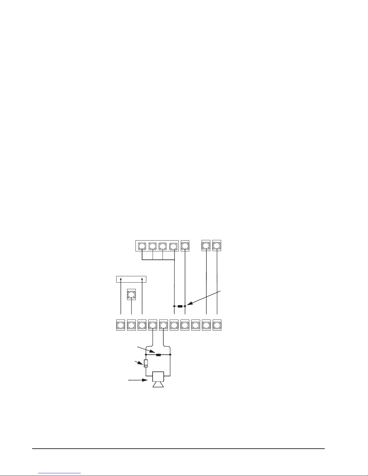
Supervised Siren Module must be wired to the Model 4720. To warn of a
fire, the module provides a UL temporal-three siren that uses three distinctive, repeating
short beeps. The module converts the communicator’s non-supervised, pulsed fire
cadence to a supervised, temporal-three fire cadence. This module also provides a
distinctive supervised burglary (police) siren. See Figure 2a for details on wiring the
module to the Model 4720. For addi tio nal i nfo rma tion, s ee the Reg ency Su per vise d Siren
Module Installation Instructions (P/N 466-1584).
GND
COM
1
4.7k Ohm
12V
INTRU-
ALARM
P3
13
BURG
2
FIRE
ALARM
FIRE
EOL RESISTOR 49-365
(LOCATE AT SIREN)
1A, 50V DIODE**
IN 4001 07-001
(LOCATE AT SIREN)
SIREN/SOUNDER**
ZONE LOOP POWER
1211
13
SION
REGENCY
MODEL 4180
STATUS
DISPLAY
MODULE
CONNECTOR
AND
TERMINAL
SIREN+SIREN
--
4
3
5
+–
ZONE
16*
INPUT
38
14
NO
C
7
6
* OR ANY ZONE INPUT PROGRAMED AS A
NORMALLY-OPEN SUPERVISORY INPUT.
** NOTE POLARITY.
GND
+12V
REGENCY MODEL 4720(A)
56
4.7K OHM EOL RESISTOR
600-7630 (LOCATE AT
SUPERVISED SIREN MODULE)
COM
NC
8
+12V
9
10
SUPERVISED SIREN
MODULE TERMINALS
PANEL TERMINALS
8457G30B.DSF
Figure 2a: Connecting the Supervised Siren Module to the Model 4724
4
Page 15

Regency® Model 4720 Control/Communicator Installation Manual (P/N 150476, Rev. A) Revised 10/98
2.3.4 NFPA 72 Central Station Signaling and
Local Protective Signaling Systems (UL 864)
All commercial fire installations must comply with the following, plus the separate requirements for
NFPA 71 and/or NFPA 72A, whichever apply.
1. The models listed below are required:
Model 4433 (4430) Remote Touchpad (1 or more)
* Model 4165 UL Transformer Enclosure (2)
* Model 4195 Auxiliary Power Supply (Includes 1 Model 9227)
Model 6712 Rechargeable Battery (2)
* Model 4184 Watchdog Trouble Module
* These items are available as a kit by ordering one Model 4722.
2. All wiring to and from the Model 4720 cabinet must be enclosed in conduit.
3. The AC Loss Hours option must be set between six (6) and 12 hours.
4. The Model 4195 and two (2) batteries must be used.
5. Total standby current must not exceed 350 mA.
6. Each Model 9220 must be installed inside of a Model 4165 transformer housing.
7. The thr ee pan ic keys ( FIRE , POL , and AUX) must be disab led for comme r cial f ir e appl ic ati ons.
8. Because Code 0 and Code 1 can activate the Walk Test mode, which prevents alarms from
responding, these codes must NOT be given to the user in UL fire applications.
2.3.4.1 NFPA 72 Central Station Signaling Systems
(Formerly NFPA 71)
The following additional requirements must be met for UL fire communicator installations:
1. The Model 4175 Dual Line/Monitor is required.
2. The 2 Phone Lines option MUST be selected.
3. The Ground Start option MUST NOT be selected.
4. The Line Monitor option MUST be selected and the Model 4175 Dual Phone Line
Monitor must be installed.
2.3.4.2 NFPA 72 Local Protective Signaling Systems
1. The Model 4160 Supervised Bell Module is required.
2. The Model 4160 must be used to supervise the bell(s).
3. The Model 4184 Watchdog Module must be used to monitor for the interruption of
program cycle and wire-to-wire faults in the touchpad wiring.
2.3.5 Grade A Mercantile Requirements (UL 365)
The following requirements must be met for UL Grade A Mercantile installations:
1. A listed tamper switch must protect the inside front door of the enclosure; this switch must be
connected to an intrusion input zone of the control unit which is programmed as a perimeter
zone.
2. A separately listed Ademco AB-12 Bell In Box must be used with the control unit.
3. The tamper switches of the alarm bell must be connected to a 24-hour zone. No other initiating
devices may be connected to this loop. The outer housing of the bell box must be grounded. The
bell circuit should be installed in accordance with UL 86 1.
4. All bell wiring must be run in its own conduit and it must be connected to the control unit using
its own knockout hole.
5. The 4720 may be used with any UL Listed receiver that can accept one of the six Model 4720
formats.
6. The Model 5255 On-Site Printer must be used when the Exception OP/CL option is selected.
5
Page 16
Regency® Model 4720 Control/Communicator Installation Manual (P/N 150476, Rev. A) Revised 10/98
7. All unused knockout holes must be plugged using bolts and washers (available from ITI, Model
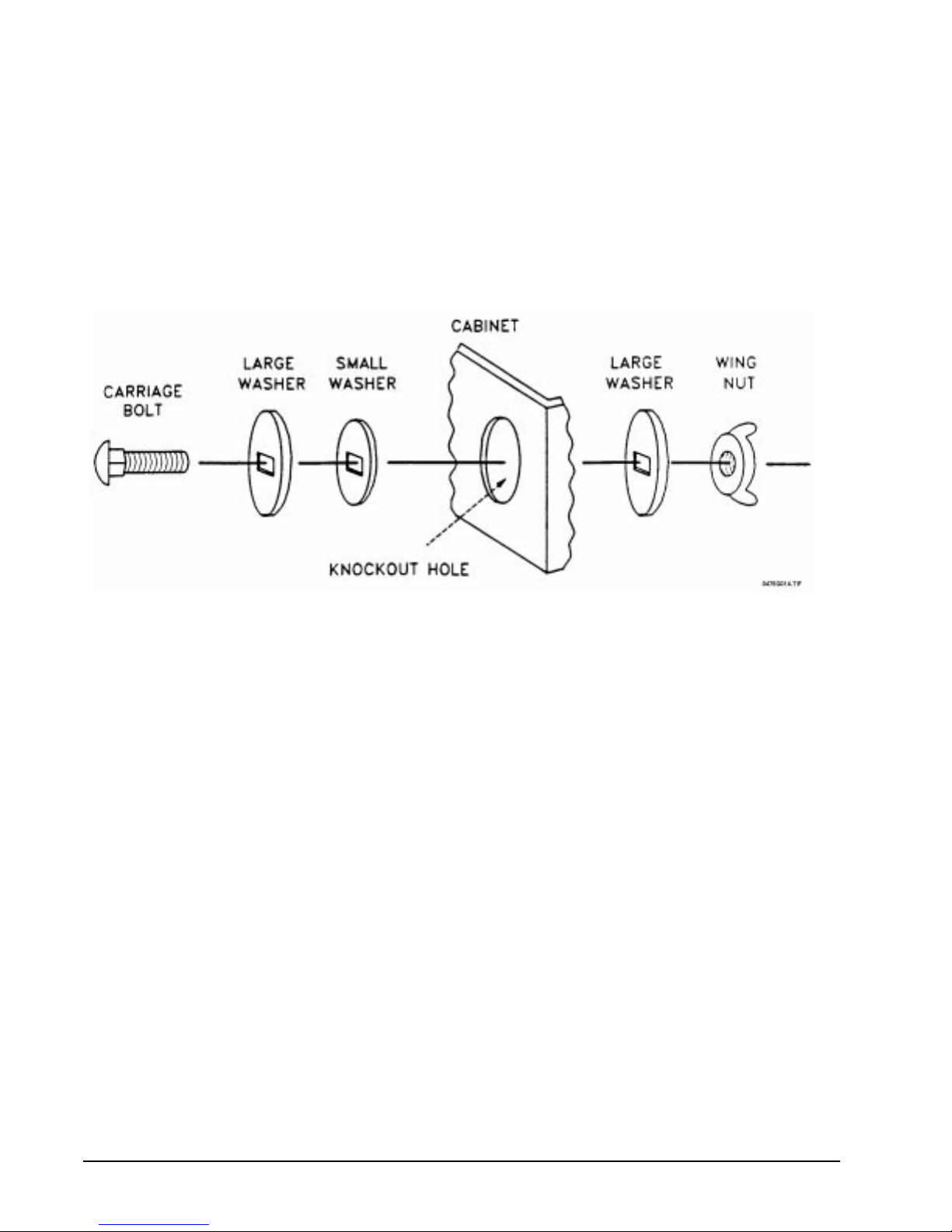
7600, six sets per package). To do this, follow the directions below (see Figure 2.3.5a):
1. Remove all unused knockouts.
2. Install the carriage bolt and three washers as shown in the diagram below.
3. Firmly tighten the wing nut.
Note: The smallest washer should be placed on the inside of the hole in the cabinet.
8. Four pan head screws #8 × 3'', type AB (thread-forming tapping screws) must be placed in the
Model 4720 cabinet cover to increase the panel’s resistance to attack.
Figure 2.3.5a: Knockout Plug Installation Diagram
WARNING: Because of the tamper switch on the Model 4720 cabinet, an alarm will occur when installing the
battery, since the door must be open when power is applied. There are two (2) ways of dealing with
this:
1. Let the alarm occur, then close and lock the cover. Go to a touchpad and press MUTE, MUTE,
then enter your code to reset the alarm. T o reset the dialer , press 3, TEST code. Finally, to set the
time, press 9, TEST code.
2. Before connecting the battery, close the cover, then connect the 9220 transformer. Go to a
touchpad and set the time (or press MUTE, MUTE), then press 2, TEST code. The LCD will
display WALK TEST. In this mode, reporting is disabled, and you may open the Model 4720
cabinet and connect the b attery. After closing the cover , pr ess MUTE , MUTE, MUTE to resume
normal operation.
Note: During a Walk Test, the system will not respond to real fire alarms.
6
Page 17

Regency® Model 4720 Control/Communicator Installation Manual (P/N 150476, Rev. A) Revised 10/98
2.3.6 Fire System Test Procedure for UL 985 Systems
In a residential fire system, it is required to periodically test the bell (or bells) on standby power
only. This test must be performed weekly according to the following procedure:
1. Call the central station and report that you are going to conduct a test.
2. Make sure that the system is not armed.
3. Remove the two (2) screws which secure the power transformer enclosure cover (Model 4165
Transformer Housing).
4. Unplug the transformer from the 120-V
receptacle.
AC
5. Press TEST, followed by the access code, at the touchpad. The bell (or bells) should sound for a
few seconds. The test will be recorded at the central station.
6. Plug the transformer back into the receptacle.
7. Replace the enclosure cover and secure with the two (2) screws. This completes the test
procedure.
Note: While the transformer is unplugged, the system may sound AC trouble. If this situation should
occur, press MUTE, MUTE to silence the trouble. The trouble will automatically clear within one
minute after the transformer has been reinstalled.
3 Control Panel Description
CAUTION:
To avoid the risk of electrical shock,
DO NOT
apply power to
the Model 4720 until told to do so in this manual (Section 8).
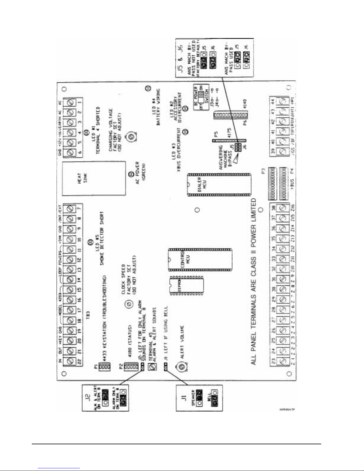
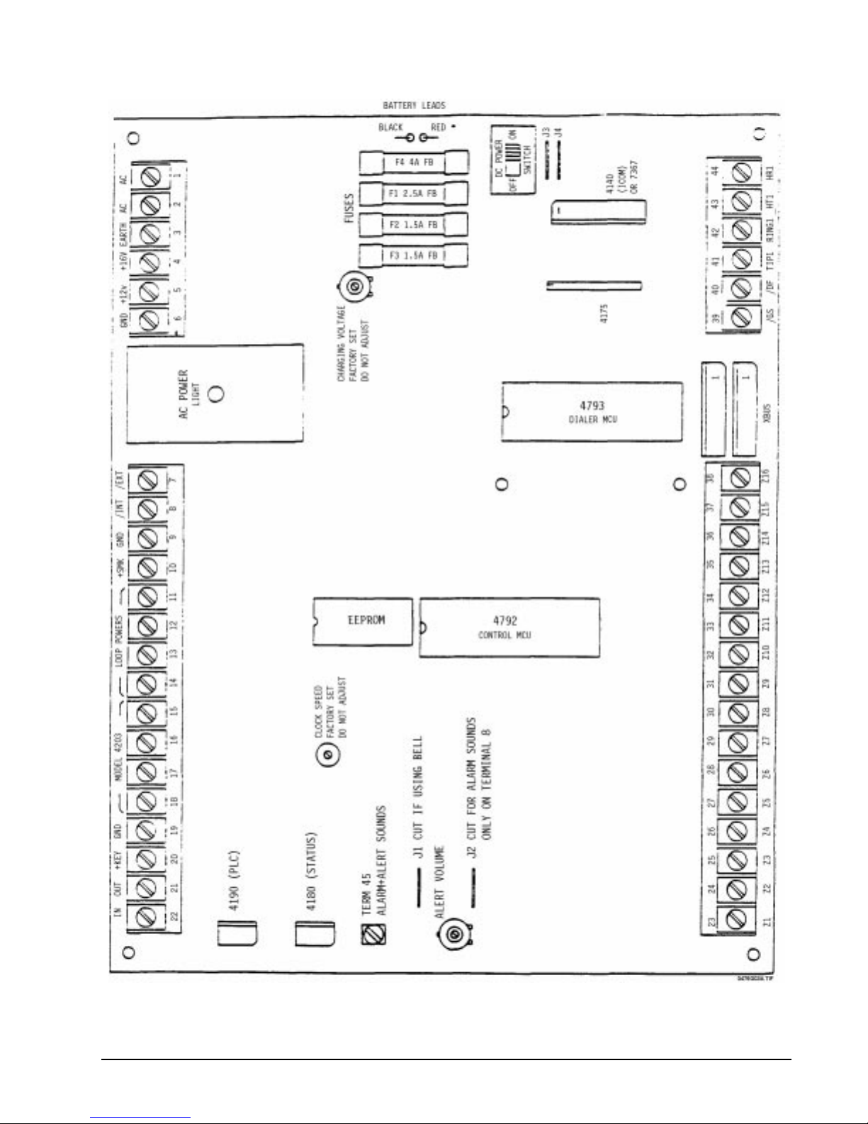
Figure 3a represents the Model 4720 Revision L printed circuit board. Figure 3b shows the printed circuit board for
earlier revisions. The PC board contains the switches, fuses, electronic components and connectors needed to
install, monitor, and protect the system. The following paragraphs describe components that the installer will have
to connect, program, adjust, or periodically replace.
7
Page 18
Regency® Model 4720 Control/Communicator Installation Manual (P/N 150476, Rev. A) Revised 10/98
Figure 3a: 4720 Printed Circuit Board,
Revision L
8
Page 19
Regency® Model 4720 Control/Communicator Installation Manual (P/N 150476, Rev. A) Revised 10/98
Figure 3b: 4720 Printed Circuit Board,
Prior to Revis io n L
9
Page 20
Regency® Model 4720 Control/Communicator Installation Manual (P/N 150476, Rev. A) Revised 10/98
3.1 Battery Cables
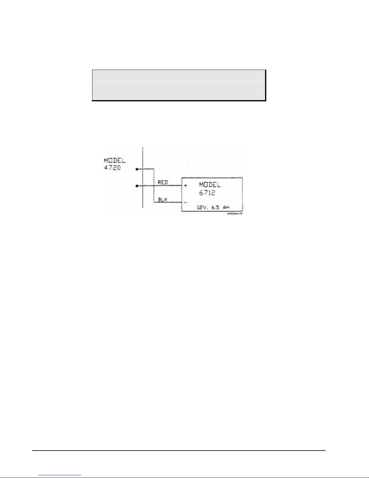
The red (+) and black (–) battery cables are used to connect a 12-V
rechargeable battery (Model 6712—
DC
not provided) to the system. The battery provides backup power to the Model 4720 in the event of AC
power interruptions (failures).
CAUTION:
Observe proper polarity when connecting the battery cables of
the Model 4720.
Note: The Model 6712 12V, 6.5-AH battery will provide at least four (4) hours of standby operation to the basic
4720 system. Two (2) 6.5-AH batteries are required for household and commercial fire installations. The
use of accessories may reduce standby operation time so that additional battery capacity may be needed.
Note: If the AC transformer is unplugged for more than 24 hours, the battery must be disconnected to prevent it
from being discharged.
Figure 3.1a: Battery Connection—PC Boards Prior to Revision L
3.2 DC Power Switch
The DC power switch is used to remove DC power from the ci rcu itry of the Mod el 4720. When th is swi tch
is in the OFF position with AC connected, the only thing that remains functional is the battery charging
circuit. If AC is not connected, the standby battery should not be connected, because leakage current
through the charging circuit could discharge the battery over a period of time. See Section 3.12.3 for
information on enabling and disabling the DC power switch.
3.3 Overcurrent Protection
3.3.1 PolySwitch
®
Circuit Protectors
Starting with the Revision L printed circuit board, all fuses have been replaced with PolySwitch
(copyright Raychem) circuit protectors. The PolySwitch's normally very small resistance (less than
1 ohm) undergoes a lar ge, abrup t increase when it g ets heated by an ov ercurrent cond ition. Wh en the
current returns to an allowable value, the PolySwitch resets automatically, allowing normal circuit
operations to resume. The protector requires no manual resetting or replacement. If a red LED is on,
determine where the problem is (refer to Table 3.4a) and correct it. The LED will turn off.
10
Page 21

Regency® Model 4720 Control/Communicator Installation Manual (P/N 150476, Rev. A) Revised 10/98
3.3.2 Fuses
PC board revisions prior to Revision L still use Revisions A-K for overcurrent protection.
• F1 is a 2.5-A Fast Blow Fuse that provides overcurrent protection for an AC Siren Speaker
connected to Terminal 4 of the Model 4720.
• F2 is a 1.5-A Fast Blow Fuse that provides overcurrent protection for touchpads and any
accessories connected to Terminal 5 of the Model 4720.
• F3 is a 1.5-A Fast Blow Fuse that provides overcurrent protection for expansion modules and
smoke detectors connected to Terminal 10 of the Model 4720.
• F4 is a 4-A Fast Blow Fuse that provides overcurrent protection to the battery.
CAUTION:
To avoid fire hazards, the Model 4720 is designed with backup
nonreplaceable fuses in series with the replaceable fuses
(power-limited design). It is
replace fuses with
AMP
rating as the old fuse. If you replace a fuse with a higher-
FAST-BLOW
VERY IMPORTANT
type fuses with the
that you
SAME
rated or slow-blow type fuse, the nonreplaceable fuse will
blow, and the panel will have to be returned to the factory for
repair.
NEVER
put a jumper across any fuse. A jumper across a
replaceable fuse will cause one of the nonreplaceable fuses to
blow. A jumper across a nonreplaceable fuse could cause a
fire.
When a replaceable fuse blows, find the cause of the excess
current by (1) using an ohmmeter and (2) replacing the fuse,
then connecting up one device at a time to see which device
causes the fuse to blow. Repair the short, then replace the
fuse with the same type and rating. Keep spare fuses in your
tool kit.
3.4 LEDs
The red LEDs are normally OFF, and come ON under the following conditions:
Table 3.4a: Red LED Indications
LED # Location on PC Board Condition(s) Causing Red LED to Light
1
Top right corner Terminal 4 (AC siren speaker) overcurrent.
2
Lower right side Terminal 5 (touchpads and accessories) ove r-
current (higher than 1.1 A)
3
Lower right side XBUS overcurrent (higher than 1.1 A).
4
Middle, right side Battery wired backwards.
5
Top, center Terminal 10 (smoke detector) overcur rent .
3.5 Earth Grounding Wire
The magnetic field of a nearby lightning strike can induce damaging currents in the wiring of an alarm
system. Even distant strikes can affect the panel through the AC or telephone wiring. The 4720 has built-in
transient protection devices, but in order to work, they must be able to shunt the transient currents to earth
ground. The green Earth Grounding Wire (included) must have one end installed under one of the four (4)
mounting screws of the Model 4720 print ed circu it boar d. Th e oth er end must be connec ted to a go od eart h
ground. If this is not available via the ground wire of the building's 3-conductor AC wiring, then a separate
heavy gauge wire should be run to a metal cold water pipe or grounding stake. This wire should be run as
short as possible, and sharp bends should be avoided.
11
Page 22

Regency® Model 4720 Control/Communicator Installation Manual (P/N 150476, Rev. A) Revised 10/98
3.6 AC Power Light
The green AC power light is on wh enev er AC p owe r is pre s ent, the DC p owe r sw itc h is in t he ON pos iti on
and all fuses are intact.
3.7 Touchpad Volume Control
The touchpad volume control is a potentiometer which controls the volume of the trouble alert and
annunciator tones at the internal speakers. Rotate the control clockwise to increase the volume.
3.8 Charging Voltage Adjustment (Factory Set)
This is used to adjust the voltage lev el that ch ar ges the back up batt ery. This potentiometer is adjus ted at the
factory. Do NOT attempt to adju st the potentiometer in the field as it may result in damage t o the battery.
3.9 Clock Speed Adjustment (Factory Set)
Used to adjust the accuracy of the real-time clock. This adjustment is made at the factory.
3.10 Cable Connectors
3.10.1 Model 4660C Series Touchpad Connector—Troubleshooting (P1)
The PLC connector is a 4-pin conne ctor that is used to co nnect t he Mod el 4660 series tou chpads f or
troubleshooting.
The following table lists the four (4) pins and shows which terminal each connects to on the Model
4660C/4660R touchpad
.
PLC Connector (4-pin) 4600B/C/R Touchpad
1
2
3
4
3.10.2 Status Connector (P2)
1
2
3
4
The Status connector is a 5-pin connector used to connect the Model 4180 Status Display Module to
the Model 4720.
3.10.3 Phone Line Monitor Connector (P5)
This 12-pin connector is used to mount the Model 4175 Dual Phone Line Monitor Module onto the
Model 4720 printed circuit board.
3.10.4 Intercom Module Connector (P6)
This 12-pin connector is used to connect the Model 4140 Intercom Module ICOM connector to the
Model 4720 printed circuit board. The 7369 Listen-in Module can also be connected here, if the
Model 4140 is not used.
3.11 Expansion Connectors (P3 and P4)
The Expansion Bus connectors are used to connect any two (2) of the models listed below. The Models
4110 - 4150 also have two (2) connectors, allowing them to be daisy-chained toge ther. Expansion bus
wiring should not exceed four (4) feet in length and must be run in conduit.
12
Page 23

Regency® Model 4720 Control/Communicator Installation Manual (P/N 150476, Rev. A) Revised 10/98
Be sure to maintain a physical separation of at least one-half inch between the field wires and any
expansion device connection points. This will prevent transient damage to the connection points.
* Model 4110 Zone Expander (SmartSensor)
* Model 4115 Zone Expander (SmartSensor)
* Model 4125 Zone Expander (Hardwired)
* Model 4130 Zone Expander (RF)
Model 4140 Intercom
Model 4150 Relay Module
Model 5520 Programmer
Model 5260 Printer Interface or Model 5255 On-Site Printer (discontinued)
* Note: If a combination of these models are used, they must be given unique addresses. This will be explained in
the installation section of this manual (Section 12).
Connector Pin Descriptions
P1: 4660B/C/R Touchpad Quick-Connect
(Troubleshooting)
1
2
3
4
GND (circuit ground)
+12 V (LED 2 or Fuse F2)
/SERIAL OUT
/SERIAL IN
P2: 4180 Status Relay Module
1
2
3
GND
+12 V (LED 3 or Fuse F2)
LATCH ENABLE PULSE
OUT
4
5
P3 and P4: XBUS (Expansion Devices)
1
2
3
GND
+12 V
/DEVICE RESET
SERIAL CLOCK OUT
SERIAL DATA OUT
7
8
9
/HS OUT
XD0
XD1
OUT
4
5
6
XA0 OUT
XA1 OUT
XA2 OUT
P5: 4175 Dual Line Monitor Module
1
2
3
GND
+12 V (current limited)
/MONITOR SAMPLE PULSE
10
12
XD2
11
XD3
/HS IN
OUT
4
5
6
7
8
9
10
11
12
/LINE2 OUT
/RINGING IN
/MONITOR2 IN
/MONITOR1 IN
EARTH GND
TIP1
RING1
SWITCHED TIP1
SWITCHED RING1
13
Page 24

Regency® Model 4720 Control/Communicator Installation Manual (P/N 150476, Rev. A) Revised 10/98
P6: 4140 Intercom/T elephone/Lis te n-in
or 7369 Listen-in
1
2
3
4
5
GND
+12 V (LED 2 or Fuse F2)
LISTEN ENABLE OUT
/DIAL
CONTROL AUDIO ENABLE
OUT
6
7
8
9
10
11
3.12 Jumper Blocks and Jumper Wires
CONTROL AUDIO OUT
TELEPHONE AUDIO
EARTH GND
SWITCHED RING1
HOUSE RING1
HOUSE RING2
Note: Starting with PC board Revision J, J1 and J2 are jumper blocks instead of jumper wires. Instead of cutting
the jumper wire, move the jumper block to the left (“out”) position. J3 and J4 are still jumper wires on the
Revision L PC board.
Jumper blocks J5 and J6 are new with the Revision L PC board. See Section 3.12.4.
3.12.1 Jumper Block J1
If a siren (speaker) is used, leave this jumper block in the right position (jumper not cut, in earlier
revisions). Move it to the left position (jumper cut) if a DC bell or DC siren is used.
3.12.2 Jumper Block J2
If you want both alarm tones and alert ton es to be present o n Terminals 8 and 45, leave jumper block
J2 in the right position (jumper not cut). When you move Jumper Block J2 to the left position
(jumper cut), only the alarm tones will be present at Terminal 8 but both tones will be present at
Terminal 45.
3.12.3 Jumpers J3 and J4
With Jumpers J3 and J4 left in place, the DC Power switch does not function. This is necessary for
NFPA and California Fire Marshall applications. For burglary applications, these jumpers may be
cut to enable the DC Power switch.
3.12.4 Jumper Blocks J5 and J6 (Starting with Revision L PC Board)
Jumper blocks J5 and J6 (new with the Revision L printed circuit board) control the Answering
Machine Bypass feature. These two (2) jumper blocks are located just to the left of the Model 4175
Phone Header. When NO 4175 is used, J5 and J6 should be to the right, next to the Model 4175
header. This allows downloading to take place even when the user has an answering machine.
When a 4175 is to be used (NO answering machine bypass), the jumper blocks must be in the left
position. If they are not in the left position, it is impossible to plug the Model 4175 into its header.
Make sure you put each jumper block on its own header (horizontal position)—Do NOT place one
jumper block across both the J5 and J6 headers.
14
Page 25

Regency® Model 4720 Control/Communicator Installation Manual (P/N 150476, Rev. A) Revised 10/98
3.13 Plug-On Terminal Strips
The Model 4720 uses plug-on terminal strips, which allow you to change the panel without unscrewing
each terminated wire.
3.13.1 Terminal Strip Removal
1. Tag each of the four (4) terminal block wire bundles, so the blocks can be reinstalled in the
correct positions.
2. Disconnect the 9220 AC Transformer and the battery cables.
3. Each terminal block is held by two (2) catches on the outside. To remove the block, pull up and
out on the inside of the block.
3.13.2 Terminal Strip Replacement
Check that each pin on the terminal block is straight, as crooked pins can damage the base portion
upon insertion.
Position the terminal block directly over its base and press straight in. The block will snap into
place.
15
Page 26

Regency® Model 4720 Control/Communicator Installation Manual (P/N 150476, Rev. A) Revised 10/98
3.14 Model 4720 Terminal Strip Description
Terminal # Terminal Description Electrical Ratings
1 AC input 16.5 VAC, 60 Hz, 40 VA
2 AC input 16.5 VAC, 60 Hz, 40 VA
3 Earth Ground
4 Siren Power
5 Auxiliary (Bell) Power
6 Circuit Ground
7 External Speaker/Bell Output (Active Low) 500 mA max.
8 Internal (Touchpad) Speaker Output (Active Low)
9 Circuit Ground
10 Smoke Detector Power 11.2 VDC - 14 VDC, 150 mA max. *2 *3
11 Loop Power +12 VDC, 50 mA max. (current limited)
12 Loop Power +12 VDC, 50 mA max. (current limited)
13 Loop Power +12 VDC, 50 mA max. (current limited)
14 Loop Power +12 VDC, 50 mA max. (current limited)
15 Optional output for use with Mode l 472 4 Contr ol
Expander
16 Model 4203 Touchpad Pin 1
17 Model 4203 Touchpad Pin 2
18 Model 4203 Touchpad Pin 3
19 Touchpad Ground
20 Touchpad Power
21 Data Output to Touchpad
22 Data Input From Touchpad
23 Zone 1 Input
24 Zone 2 Input
25 Zone 3 Input
26 Zone 4 Input
27 Zone 5 Input
28 Zone 6 Input
29 Zone 7 Input
30 Zone 8 Input
31 Zone 9 Input
32 Zone 10 Input
33 Zone 11 Input
34 Zone 12 Input
35 Zone 13 Input
36 Zone 14 Input
37 Zone 15 Input
38 Zone 16 Input/Mechanical Key Input
39 Ground Start Output 100 mA Max. Active Low
40 Dialer Failed Output 100 mA Max. Active Low
41 Telco Tip
42 Telco Ring
43 House Tip
44 House Ring
45 Audio Output (Alarm and Alert Tones)(Active Low)
16 VDC unregulated (1-A load) max.
10.2 VDC - 13.7 VDC, 1 A max.
(PolySwitch-p rotected to 1.1 A min. Revision L and later PCB revs .)*4 (fused
1.5 A - earlier revisions)
*2 *3
*1
* Note 1: Terminal 4 (16 V) will be at 20 V under normal standby conditions (non-alarm).
* Note 2: Each de vice connected to Terminal 5 or 10 must be rated for the voltage ranges specified. The minimum
voltage occurs when AC power is off and the battery is discharging under load. The maximum voltage
occurs when AC power is on and the output is not loaded.
* Note 3: The total current drain of Terminal 5, Terminal 10, all touchpads, and all XBUS expansion devices, must
not exceed 1.35 A (see Table 4.1.1.0a).
* Note 4: See Section 3.3.1 for an explanation of PolySwitch protection.
UL note: Refer to wiring diagram on the unit for ratings/connections.
16
Page 27
Regency® Model 4720 Control/Communicator Installation Manual (P/N 150476, Rev. A) Revised 10/98
3.15 Non-UL Wiring Diagram
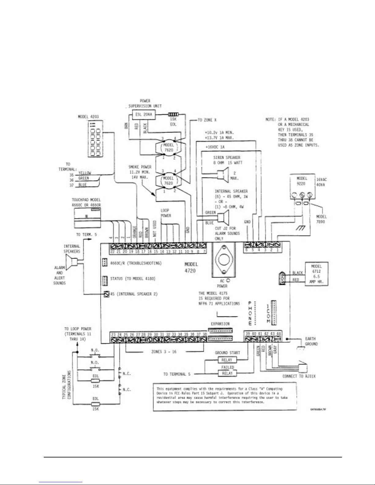
For UL installations, refer to the wiring diagram mounted in the front cover of the Model 4720 only. This
diagram contains items which are not currently acceptable for UL installations. These items are the Model
4203 Touchpad, PLC Connector, 7140 relays, and external siren driver. The UL wiring diagram also
contains various electrical ratings and restrictions.
Figure 3.15a: Model 4720 Non-UL Wiring Diagram
17
Page 28
Regency® Model 4720 Control/Communicator Installation Manual (P/N 150476, Rev. A) Revised 10/98
4 4720 Control Panel Overview
4.1 Current Draw Calculations
4.1.1 Total Standby and Alarm Current Draw
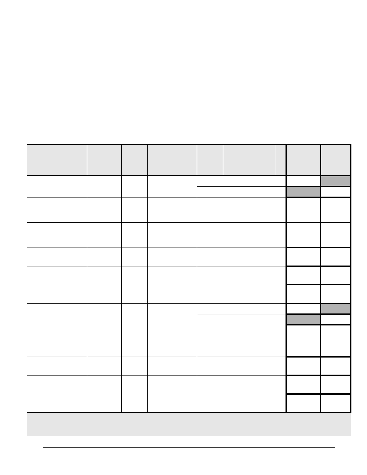
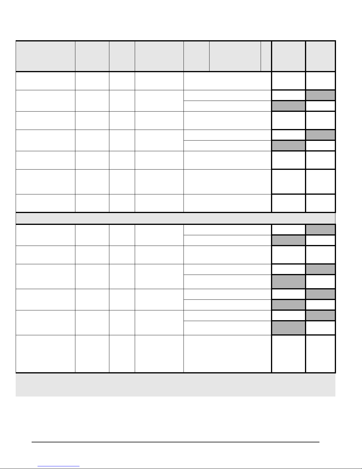
Table 4.1.1.0a is a worksheet to help you calculate the amount of current the system draws on
standby and in an alarm condition, to make sure the installation does not exceed power supply and
calculating current draw for battery capacity. The second column shows the LED that indicates
excessive current draw for each accessory, for PC board Revision L and later revisions. The third
column shows the fuse through which each accessory draws power, for earlier PC board revisions.
The remaining columns are explained in the instructions below.
To use the worksheet in Table 4.1.1.0a:
1. Look down through the Device column to identify which devices ar e and are n ot inc lude d in th is
installation.
a. Cross out any device that is not used, extending the line all the way across the page.
b. In the spaces provided, write in any other devices not printed on the sheet.
c. For each device, list the number of devices being used in the # of devices column. The
maximum number of devices is shown in parentheses ( ).
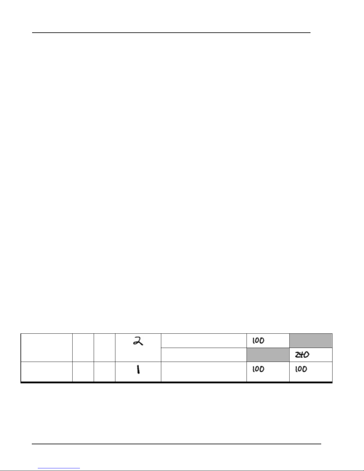
Example: Suppose your installation included two (2) LCD Touchpads, a 4115 Zone Expander, and no 4110
4660B/C/R LCD
Touchpad
4115 Zone
Expander
2. Go through the Curr ent per devi ce column and fill in any missing current ratings for the devices
used. Note that some devices hav e dif fe ren t ratings f or stan dby and al arm cond itio n. For de vices
not mentioned in the manual, refer to the device manual for the current ratings.
3. For each device, multiply the # of devices times the Current per device, and enter the total in
either the Total standby current or Total alarm current column, whichever is appropriate. For
devices with different standby and alarm currents, be sure to do the calculation for each rating.
Do NOT write in the shaded areas.
Zone Expander. After you had worked this far in the procedure, part of your worksheet would
appear as shown below:
(This is NOT the worksheet. It is an
EXAMPLE, to show you how to
complete the worksheet. The
worksheet begins on the next page.)
. . .
2F2
(15 max. - not UL)
3F3
×
×
×
(2 max.)
Standby: 50 mA =
mA
Alarm: 120 mA =
mA
100 mA =
mA mA
. . .
18
Page 29
Regency® Model 4720 Control/Communicator Installation Manual (P/N 150476, Rev. A) Revised 10/98
4. Add up each of th e two Total columns and write the totals in the spac es on the last line (4th page)
of the worksheet. When you add the columns, remember to:
• Include the values from ALL three (3) pages of the worksheet (Table 4.1.1.0a).
• Include both printed and handwritten values.
5. For UL installations—To obtain 24-hour standby battery power , the Total standby current draw
must not exceed 200 mA when using the Model 4720 only, and must not exceed 350 mA when
one 4195 is used.
6. Calculate the Alarm current draw on the protective devices indicated by LEDs 2 and 3 (F2 and
F3 in PC board revisions prior to Revision L), following the directions in Section 4.1.2. The total
combined Alarm current draw on these protective devices must not exceed 1300 mA. To obtain
more active current, touchp ads can be power ed by the Model 419 5, which provi des an addition al
2500 mA.
Table 4.1.1.0a: Current Load Worksheet
Device LED
(Revision
L
Fuse #
(Prev.
Revs.)
# of Devices
(Max. Allowed)
Times Current Per
*2
Device
= Total
& Later)
11× Standby: 95 mA = 95 mA
4720*
× Alarm: 130 mA = 130 mA
4203 SlimLine
Weather Resistant Touchpad*
4205 SlimLine
Access Control
(4 max.—not UL)*
1
2F2
15 max.—not UL)
× 10 mA = mA mA
2
× 10 mA = mA mA
Touchpad
4300 Swipe Card
Reader
4310, 4312 Proxim-
ity Card Readers
4420 Card Reader
Interface
4660B/C/R LCD
Touchpads
2F2
(15 max.—not UL)
2F2
(15 max.—not UL)
2F2
(15 max.—not UL)
2 F2 15 (or 5 for 24-hour
standby)
× 25 mA = mA mA
× 130 mA = mA mA
× 20 mA = mA mA
× Standby: 52 mA = mA
× Alarm: 112 mA = mA
Standby
Current
Total
Alarm
Current
4110 Zone
3F3
Expander
(replaced by
4115)
4115 Zone
3F3
Expander
4125 Zone
3F3
Expander
4130 Zone
3F3
Expander
* Note 1: If no LED or fuse is shown, the accessory is resistively current limited.
* Note 2: Not UL = Not investigated by UL.
* Note 4: Not Ul = The maximum number shown for smoke detectors is for the entire installation (NOT per zone).
(2 max.)
× 105 mA = mA mA
× 100 mA = mA mA
(2 max.)
× 30 mA = mA mA
(2 max.)
× 100 mA = mA mA
92 max.—not UL)
19
Page 30
Regency® Model 4720 Control/Communicator Installation Manual (P/N 150476, Rev. A) Revised 10/98
Table 4.1.1.0a: Current Load Workshe et
Device LED
4140 Intercom/Tele-
phone Controller
4150 Auxiliary Con-
trol Module
4640 Intercom Sta-
tion
4724 Control
Expander
5260 Printer Inter-
face
7369 Two-Way
Audio Listen-in
Module
5520 Desktop Pro-
grammer
Fuse #
(Revision
L
(Prev.
Revs.)
& Later)
2F2
3F3
3F3
——
3F3
2F2
# of Devices
(Max. Allowed)
Times Current Per
*2
Device
= Total
Standby
Current
(1 max.)
(1 max.)
(8 max.)
(1 max.)
(1 max.)
(1 max.—not UL)
1 × 30 mA = 30 mA 30 mA
× 100 mA = mA mA
× Standby: 100 mA = mA
× Alarm: 70 mA = mA
× 8 mA = mA mA
× Standby: 40 mA = mA
× Alarm: 40 mA = mA
× 25 mA = mA mA
× 100 mA = mA mA
Total
Alarm
Current
Smoke detectors
ESL 445AT
ESL 445C, 445CT,
445CR, 445CRT
Detection Systems
DS200-4W,
DS200HD-4W
Hochiki America,
Corp. SLK-12
Gentex 8120,
8120T, 8120P,
8120PT, 8120PH
ESL 204A Power
5F3
(7 max.) × 4
5F3
(12 max.)
5F3
(12 max.)
5F3
(10 max.)
5F3
(7 max.)
5F3 — × 40 mA = 40 mA 40 mA
× Standby: 1.5 mA = mA
× Alarm: 70 mA = mA
× Alarm: 40 mA = — mA
× Standby: .08 mA = mA
× Alarm: 25 mA = mA
× Standby: .055 mA = mA
× Alarm: 10 mA = mA
× Standby: 5 mA = mA
× Alarm: 60 mA = mA
Supervision Unit
(One required for
each smoke
detector loop)
* Note 1: If no LED or fuse is shown, the accessory is resistively current limited.
* Note 2: Not UL = Not investigated by UL.
* Note 4: Not Ul = The maximum number shown for smoke detectors is for the entire installation (NOT per zone).
20
Page 31
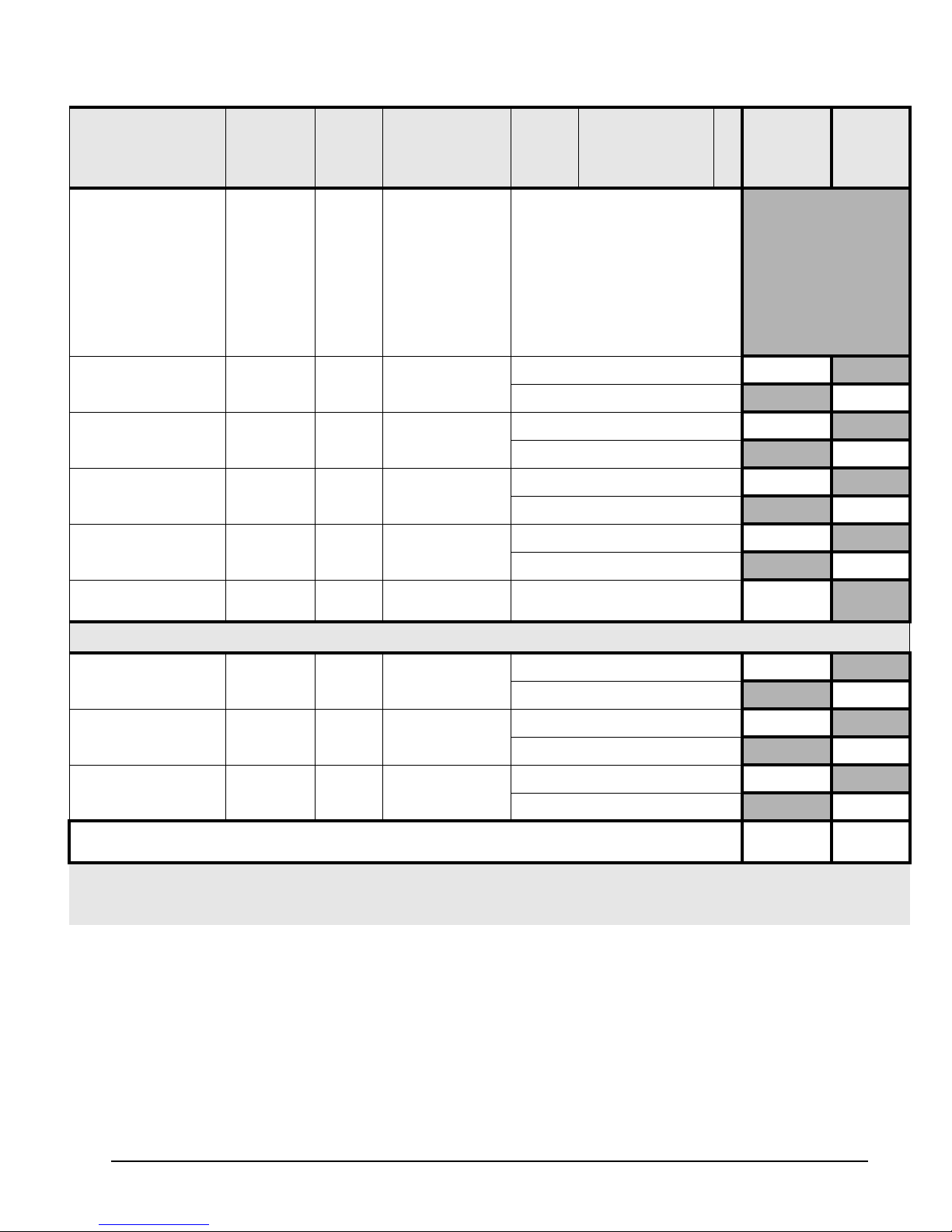
Regency® Model 4720 Control/Communicator Installation Manual (P/N 150476, Rev. A) Revised 10/98
Table 4.1.1.0a: Current Load Worksheet
Device LED
Model 7181 Univer-
sal Zone Converter
Wheelock Bell
8-ohm Speaker
45-ohm Speaker
Siren (15-watt
speaker)
(Revision
L
Fuse #
(Prev.
Revs.)
# of Devices
(Max. Allowed)
& Later)
5 F3 (1 per zone max.)
2F2
2F2
2F2
1F1
3 max.)
(1 max.)
(6 max.)
(1 max.
Times Current Per
*2
Device
(See the Model 7
tion Manual
181 Installa-
—P/N 150632,
= Total
Standby
Current
Current
in the electrical specifications section—for current
draw information. Be sure to
take the appropriate information for the configuration
in which you’ve wired the
Model 7181.)
× Standby: 0 mA = 0 mA
× Alarm: 125 mA = mA
× Standby: 0 mA = mA
× Alarm: 750 mA = mA
× Standby: 0 mA = mA
× Alarm: 133 mA = mA
× Standby: 0 mA = mA
× Alarm: 133 mA = mA
Total
Alarm
Zone Input
—
(16 max.)
× Standby: 0.6 mA = mA
Additional devices not listed above
× Standby: ____ mA = mA
× Alarm: ____ mA = mA
× Standby: ____ mA = mA
× Alarm: ____ mA = mA
× Standby: ____ mA = mA
× Alarm: ____ mA = mA
Total current ratings of all devices in system
* Note 1: If no LED or fuse is shown, the accessory is resistively current limited.
* Note 2: Not UL = Not investigated by UL.
* Note 4: Not Ul = The maximum number shown for smoke detectors is for the entire installation (NOT per zone).
4.1.2 Current Draw on Protective Devices Indicated by LEDs 2 and 3 (F2 and F3)
Calculate the alarm current drain on the p rotective devi ces indicated b y LED 2 (F2) and LED 3 (F3).
First complete the calculations in Table 4.1.1.0a on the previous pages. Then use Table 4.1.2a to
perform the following calculations:
1. Write the Total alarm current (from Table 4.1.1.0a) in Column 3.
2. If there are any additional devices that are not associated with LED 2 or LED 3 (F2 or F3), write
them in the space provided, and write their current draws in Column 2.
3. Add Column 2. Write the total in Column 3 on the line labeled Alarm current NOT associated
with LED 2 or 3 (F2 or F3).
mA
Standby
mA
Alarm
21
Page 32
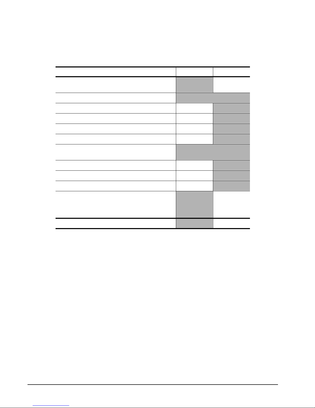
Regency® Model 4720 Control/Communicator Installation Manual (P/N 150476, Rev. A) Revised 10/98
4. Subtract the second value in Column 3 from the first value in Column 3.
(Total alarm current – Alarm current NOT associated with LED 2 or 3)
The total combined Alarm current draw on these protective devices must not exceed 1300 mA. To obtain
more active current, touchpads can be powered by the Model 4195, which provides an additional 2500 mA.
Table 4.1.2a: Current Draw on Protective Devices LEDs 2 and 3 (F2 and F3)
Column 1 Column 2 Column 3
Total alarm current
(from Table 4.1.1.0a)
Devices
NOT
on LED 2 or 3
4720 Control/Communicator 130 mA
4203 Touchpad 10 mA
4175 Phone Line Monitor 1 mA
4184 Watchdog Trouble Module 70 mA
Additional devices
NOT
associated with
LED 2 or 3:
Alarm current
NOT
associated with LED 2 or LED
3 (F2 or F3)
(Add the second column and put the total in the
third column).
ALARM CURRENT – LED 2 AND 3 (F2 AND F3)
22
Page 33
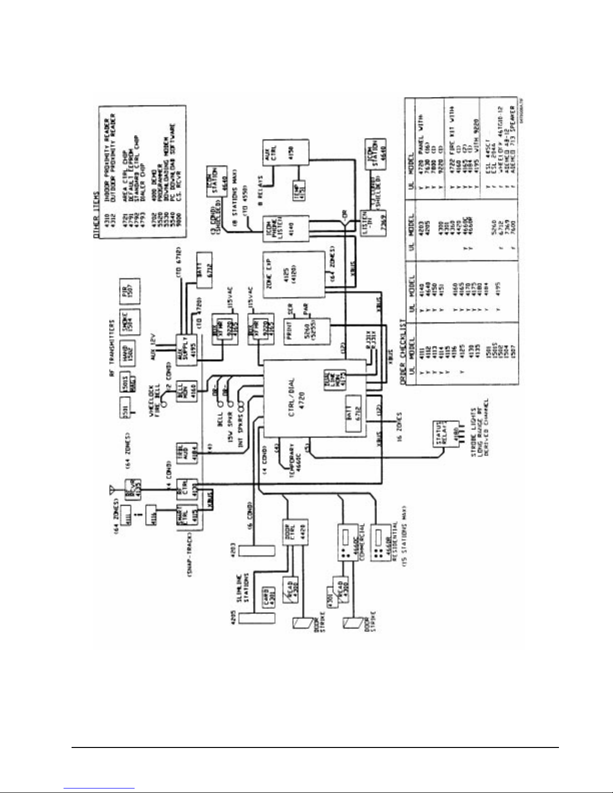
Regency® Model 4720 Control/Communicator Installation Manual (P/N 150476, Rev. A) Revised 10/98
4.2 System Planning Block Diagram
Figure 4.2a : Model 4720 System Planning Diagram
23
Page 34

Regency® Model 4720 Control/Communicator Installation Manual (P/N 150476, Rev. A) Revised 10/98
5 Wiring Precautions
To avoid induced noise (transfer of electrical energy from one wire to another), keep input wiring isolated from
high current output and power wiring. Induced noise can interfere with telephone communication, or even cause
false alarms. Avoid pulling one multiconductor cable for the entire panel. Instead, separate the wiring as follows:
• High current input/output: AC power and speaker and bell wiring
• Low current input/output: Touchpad and zone loop wiring
• Audio input/output: Telephone wiring
Wires from different groups should not be pulled through the same conduit. If you must run them together, do so
for as short a distance as possible, or use shielded cable. Connect the shield to circuit ground at the panel.
For the same reasons, wiring within the cabinet should be routed around the perimeter of the cabinet. It should not
cross the printed circuit board, where it could induce noise into the sensitive microelectronics, or pick up unwanted
RF noise from the high speed circuits.
High frequency noise, such as t hat produ ced by the induc tive reac tance of a speak er or be ll, c an also be re duced by
running the wire through ferrite shield beads, or by wrapping it around a ferrite toroid.
6 Model 4720 Control Panel Installation
6.1 Selecting a Location
When selecting a location to mount the Model 4720 control panel consider the following factors. The unit
should be mounted where it will not be exposed to extremes in temperat ure and it will be free from
moisture. The panel should be accessible to “main drop” wiring runs. The 4720 should be located well
within the secured area but should be accessible for testing and service.
24
Page 35
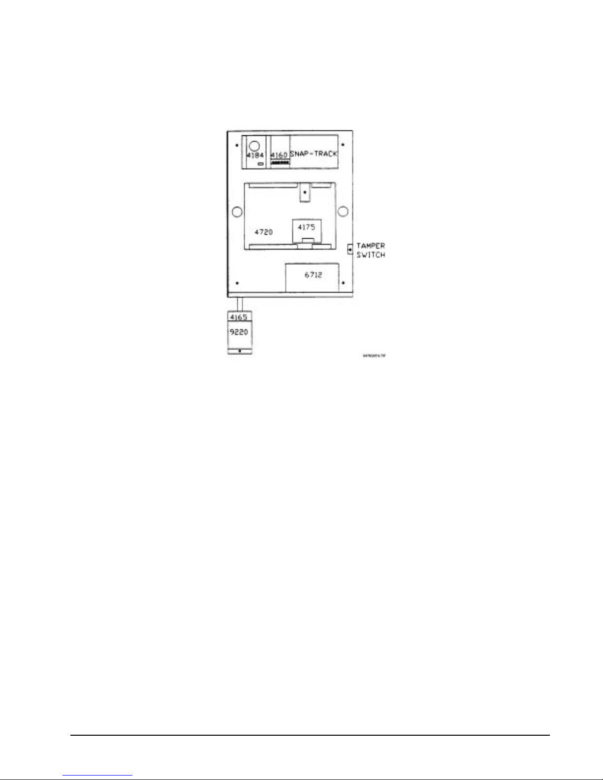
Regency® Model 4720 Control/Communicator Installation Manual (P/N 150476, Rev. A) Revised 10/98
6.2 Mounting the Model 4720
Mount the Model 4720 so it is firmly secured to the wall surface. When mounting on concrete, especially
when moisture is expected, at tach a piece of
3
/4-inch plywood to the concrete surface and then attach the
Model 4720 to the plywood. Mount all other desired components to the plywood interface.
Figure 6.2a: Suggested Mounting for the Control Panel
6.3 Installing the Model 9220 Power Transformer
An external transformer (Model 9220 included) is used to supply 16.5 V AC (40 VA) to power the system
under normal conditions and to supply charging current to the backup battery. The primary of this
transformer plugs directly into a conventional 115-V
unswitched outlet. The secondary is wired into
AC
Terminals 1 and 2 of the Model 4720 with a 2-conductor cable (preferably shielded). Use 18-gauge wire or
larger (i.e., AWG 16, 14, 12, etc.).
6.3.1 Model 4165 Transformer Housing
You must install the power transformer inside of the Model 4165 when installing the Model 4720 in
accordance with NFPA Standards.
1. Remove all power from the electrical outlet before attaching the Model 4165.
2. Remove the two (2) screws that hold the outlet to the single gang box.
3. using the two (2) screws that were removed, attach the Model 4165 box to the outlet and the
single gang box.
4. Plug the transformer into the outlet.
5. The secondary of the transformer must be run in conduit which may be attached to any of the
knockout holes.
6. Attach the housing cover to the housing plate using the two (2) screws provided.
Note: Electric door strikes and magnetic door holders are a potential source for damaging electrical
impulses. The auxiliary powe r from the Model 4720 should not be used for these devices. A
separate power source (such as Model 4195) should be used, and a reverse polarity diode should be
connected across the devices to suppress the impulses.
25
Page 36

Regency® Model 4720 Control/Communicator Installation Manual (P/N 150476, Rev. A) Revised 10/98
6.3.2 Installing th e Transformer
The main wiring diagram and Figure 6.3.2a show the connection of shielded 2-conductor cable and
the Model 7890 Transient-Surge Protector to the Model 9220 UL Listed Class II Power Transformer
(16.5 V
plugged into a 120-V
, 40 VA). Both models are included with the Model 4720. The transformer should be
AC
, 60-Hz continuous duty (unswitched) grounded outlet.
AC
WARNING:
The Model 9220 contains an internally fused secondary
winding.
DO NOT SHORT
the secondary terminals together
when power is applied or the internal fuse will blow. Be sure
the shield conductor cannot come in contact with the AC
output screws.
The Model 7890 Transient-Surge Protector will protectively clamp the AC output of the transformer,
reducing transient voltages caused by lightning and other sources. The AC power lines are the most
common source of transient/lightning damage in alarm systems. The Model 7890 consists of two (2)
bipolar transient suppressors with lugs at its connecting points.
CAUTION:
Make sure that the AC outlet you intend to use for the Model
9220 has a “good” connection to earth ground. This can be
done at the outlet, by using a digital voltmeter to measure the
AC voltage between the “hot” side of the outlet and neutral,
then comparing that voltage to the voltage reading made
between the “hot” side and the ground connection. The
difference between these two voltage readings should not
exceed 1 V
. If these voltages are not within 1 VAC, the outlet
AC
does not have an earth ground and must be grounded by
running a 14-gauge wire from the outlet to a good source of
earth ground such as a water pipe.
Note: A licensed electrician may be required to perform this
procedure.
CAUTION:
To reduce the risk of electrical shock or fire, connect directly to
a grounded (3-prong) receptacle.
26
Page 37
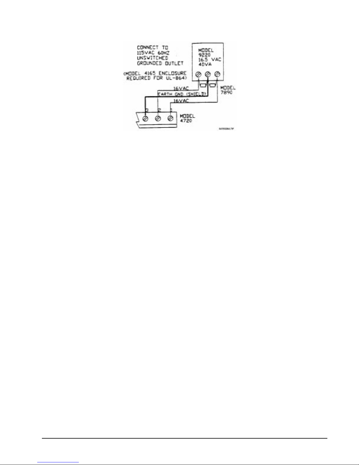
Regency® Model 4720 Control/Communicator Installation Manual (P/N 150476, Rev. A) Revised 10/98
Figure 6.3.2a: Model 9220 Transformer Connection
6.4 Model 4195 Auxiliary Power Supply
The Model 4195 provides an additional 2.5 A of current for accessory items, 1.25 each at Terminals 3 and
4. The 4195 contains an AC power light that monitors the transformer. It also allows you to use two (2)
standby batteries to double the time that the system can function on battery standby. The 4195 also has
reverse battery indicators, and output overload indicators.
The 4195 should be mounted in the plastic board mount above the Model 4720. Figure 6.4a shows how to
wire the Model 4195. Connect the red battery lead from the Model 4720 to the spade lug labeled + on the
diagram below. Connect the black battery lead from the Mo de l 4720 t o th e spa de lug l ab ele d “– ” on Fig u re
6.4a below.
To enable the Model 4195 outputs to turn off for smoke detector reset, connect Terminal 6 of the Model
4195 to Terminal 10 of the Model 4720 instead of to Terminal 5 of the Model 4720.
27
Page 38
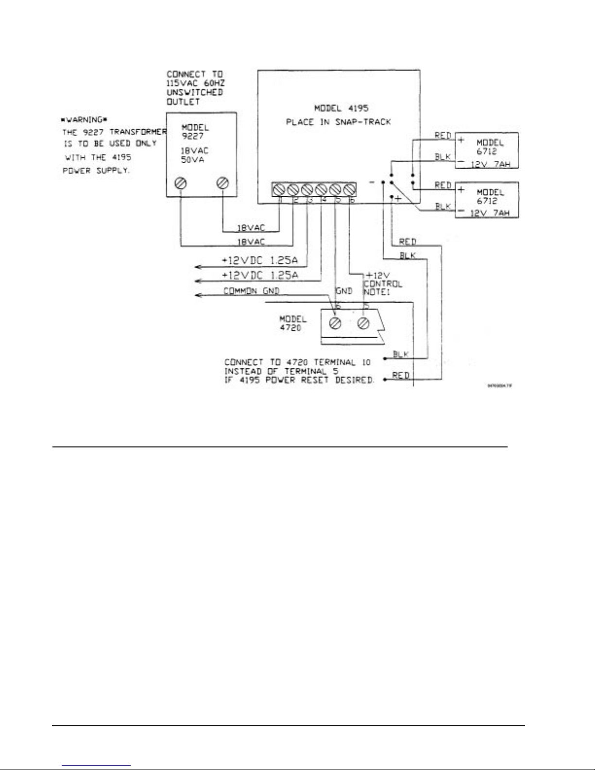
Regency® Model 4720 Control/Communicator Installation Manual (P/N 150476, Rev. A) Revised 10/98
Figure 6.4a: Wiring the Model 4195 Auxiliary Power Supply
7 Touchpad Installation
Note 1: In a UL installation, the touchpads must be mounted on a dual gang electrical box.
Note 2: If a touchpad is removed from a Model 2605/2607 and then connected to a Model 4720, the CHM and CODE2
keys won't function. The touchpad is programmed by the 2605/2607 and must be reprogrammed at the factory
before it can be used with a 4720.
7.1 Mounting the Touchpads
To mount a touchpad, follow this procedure:
1. Separate the top section from the rear mounting plate. First, insert a small flat-blade screwdriver into the
slot(s) located on the bottom edge of the frame. Push in, then lift up the top section.
2. Secure the mounting plate to the wall using the proper screw (either a #6 or a #8) with a thread
appropriate for the type of material it is going into.
The mounting plate should be oriented so that the protruding tab and the three (3) posts are towards the
bottom. Pull the wires through the hole in the rear mounting plate.
3. Wire the touchpad as explained in Section 7.2.
After all the wires are connected to the Model 4720 terminal strip, set the top of the touchpad frame
over the tabs at the top of the mounting plate, then press on the bottom until you hear it snap in to
position.
28
Page 39
Regency® Model 4720 Control/Communicator Installation Manual (P/N 150476, Rev. A) Revised 10/98
7.2 Wiring the Touchpads
All touchpads require four (4) wires to operate. The 4-conductor cable can be up to 1,000 feet long. The
minimum wire gauge is 22 AWG for runs under 500 feet and 18 AWG for runs between 500 and 1,000 feet.
Wire the touchpads as shown in Table 7.2a.
Table 7.2a: Wiring the Touchpads to the Model 4720
Touchpad
Terminal #
1
2
3
4
7.3 Daisy-Chaining Touchpads
Description 4720 Terminal
Touchpad Ground 19 (GND)
Touchpad Power 20 (PWR)
Data In (from 4720) 21 (OUT) Panel Data Output to Touchpad
Data out (to 4720) 22 (IN) Panel Data Input to Touchpad
Homerun wiring from each touchpad back to the panel is recommended. However, daisy-chaining the
touchpad wiring is permitted within the following limitations.
When touchpads are daisy-chained, the wiring leg between the panel and the first station must conduct
extra current to supply multip le to uc hp ads. Si nce t he w ir e has some r es ist an ce, th er e will b e a vo lt ag e d rop
at the end of the wire run and this dro p must be within t he toler ance of the touc hpad re quireme nt. To reduce
the drop, you should use lower resistance wire; 18 AWG is recommended. For example, suppose you want
to run a common leg for 300 feet, and then branch to two (2) touchpads, the farthest of which will be an
additional 200 feet. You plan to use 18 AWG for the common leg and 22 AWG for the two (2) branches.
Here is how you would decide if this is acceptable:
AWG Ohms/foot Ohms/1,000 feet
22 .0161 16.1
18 .0064 6.4
Model 4660B/C/R: Active current draw: 120 mA
Maximum allowed voltage drop: 2 V
For the common leg:
Maximum current = 120 mA × 2 = 240 mA (× 2 touchpads)
Resistance = .0064 ohms/foot × 600 feet = 3.84 ohms (18 AWG, 300 feet × 2)
(Note that the wire length is doubled since the current must flow out and back.)
For the longest sub-branch:
Maximum current = 120 mA
Resistance = .0161 ohms/foot × 400 feet = 6.44 ohms (22 AWG, 200 feet × 2)
Voltage drop = 120 mA × 6.44 ohms = 0.77 V
Total voltage drop at farthest touchpad: 0.92 V + 0.77 V = 1.69 V
Since this is less than the 2 V maximum allowed drop, the wiring is acceptable.
29
Page 40
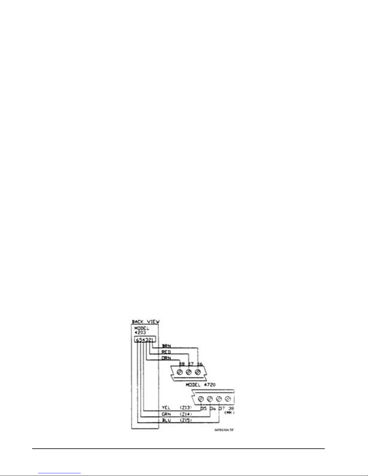
Regency® Model 4720 Control/Communicator Installation Manual (P/N 150476, Rev. A) Revised 10/98
7.4 Setting ID Codes
When installing the system, set the ID number for each t ouchpad according to the following procedure:
1. Apply power.
2. Press 0, 0, TEST (before pressing any other key sequence).
3. The display will read KEY ID=NN, BEEP=1 (NN represents the current ID number. BEEP=1
indicates that the miniature speakers in the touchpads have been enabled.)
The beep enable can be toggled by pressing MUTE. When Beep = 0, entry, exit, and trouble beeps will
not be heard at that touchpad.
Note: Key beeps will be heard at the touchpad, regardless of the Beep = 0 option.
4. Enter the new ID number, 01…15, then press TEST.
5. If there is more than one touchpad, repeat from Step 1 or 2 for each touchpad in the system, using a
different sequential ID number for each touchpad.
6. Remove power from the system by unplugging the transformer and disconnecting at least one battery
cable. You must do this before you test the touchpad.
7.5 Model 4203 Weather-Resistant, SlimLine Touchpad
7.5.1 Mounting the Model 4203
The SlimLine design of the Model 4203 allows it to be mounted on the door jamb between the
screen door and the entry door. After connecting the wires, place the insulating material behind the
touchpad. Using the screws provided, screw the touchpad to the door jamb. If the touchpad is to be
mounted on a metal surface, it will be necessary to drill two (2) pilot holes before fastening the
station to the jamb.
7.5.2 Wiring the Model 4203
Note: The last four (4) zones on the Model 4720 are used as inputs from the Model 4203. You will lose the
use of these zones for alarms.
Note: The Model 4203 Touchpad requires control chip Revision B or later.
The Model 4203 is provided with a 6-wire pigtail for connection to the Model 4720. Figure 7.5.2a
shows how to wire the Model 4203 t ouchpad to the Model 4720.
The Model 4203 is also provided with a sep ar at e f our (4) c o n du ctor pigtail cable. This cable is only
needed when connecting the Model 4203 to the M odel 2820 (see Model 2820 Installation Manual,
P/N 150492).
Figure 7.5.2a: Wiring the Model 4203
30
Page 41
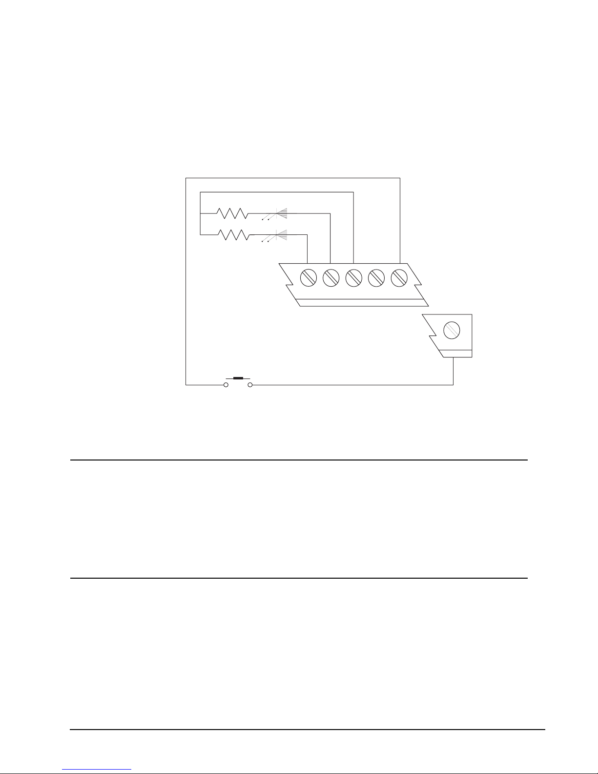
Regency® Model 4720 Control/Communicator Installation Manual (P/N 150476, Rev. A) Revised 10/98
7.6 Mechanical Keyswitch
A normally open mechanical keyswitch may be wired between Terminals 14 (loop power) and 38 (Zone
16). Figure 7.6a shows a mechanica l keyswit ch conne cted to the Model 4 720 alon g with Rea dy and Armed
Lights.
Note 1: When a mechanical keyswitch is used, you lose the use of Zones 13 through 16.
Note 2: If a mechanical key is used, you must select the Muxed (4203) Touchpads option during system
programming.
Note 3: The keyswitch option is not to be used in UL applications since supervision annunciation is not provided.
560 G REE N LE D
560 R E D LE D
N/A
18 17 16 15 14
M O DEL 4720
MOM ENTARY CLOSURE
KEYSW ITCH
N.O .
38
(Z 16)
0476G11A.DSF
Figure 7.6a: Mechanical Keyswitch Wiring
8 Powering Up the System
Note: In UL Fire applications, the system will power up as soon as you plug in the transformer. It is not necessary to flip
the switch.
Wire each accessory and auxiliary device with the power down. After you install each one, test it by applying
power again.
9 Internal Zones
This section applies to the 16 internal zones of the Model 4720 only. For information on wiring of the expansion
zones, refer to Section 12. Zones 1 through 16 (Terminals 23 through 38) may be used with normally open
contacts, normally closed contacts, or a combination of both. The illustrations below show the different types of
zone configurations. Loop power is available from Terminals 11-14.
31
Page 42
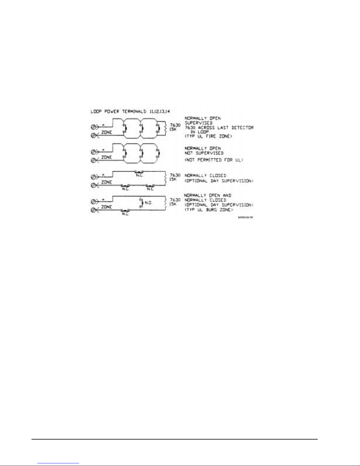
Regency® Model 4720 Control/Communicator Installation Manual (P/N 150476, Rev. A) Revised 10/98
9.1 Normally Open and Normally Closed Contact Wiring
* Supervision of either N.O. or N.C. contacts is optional (see the Model 4720 Programming Options
Description Manual, P/N 150299).
Note 1: When supervising normally open contacts, a 15-kΩ end-of-line resistor must be used.
Note 2: When using normally closed contacts, a 15-kΩ resistor must be installed in series with the loop.
Note 3: When using a combinati on of conta cts, a 15-kΩ resistor must be installed in series with the normally closed
contacts and in parallel with the normally open contacts.
Note 4: For UL installations, minimum wire gauge is 18 or larger (i.e., #16, #14, etc.). Maximum loop wiring
resistance is 250 Ω.
Figure 9.1a: Internal Zone Wiring
9.2 Smoke Detector Wiring
The ESL 445AT 12-V
, 4-wire Smoke Detector must be used when wiring fire zones on the Model 4720
DC
in a UL installation. Refer to NFPA 72E for proper smoke detector placement. Figure 9.2 shows how to
wire the 445AT Smoke Detectors ESL 445AT. The ESL 445AT Smoke Detector is rated at 1.5 mA in the
normal supervisory condition and 60 mA in the alarm condition. Refer to Table 4.1.1.0a for the maximum
number of detectors that may be used. The ESL 204A Power Supervision Unit and Model 7630 EOL
Resistor must be mounted across the last detector in the loop.
Note 1: If you want to use more than seven (7) smoke detectors, connect Terminal 1 of the smoke detector to
Terminal 3 or 4 of the Model 4195 Auxiliary Power Supply (instead of Terminal 10 of the Model 4720),
and connect Terminal 6 of the Model 4195 to Termin al 10 (ins tead of Terminal 5) of the Model 4720. When
the Model 4720 powers up, Terminal 10 of the Model 4720 will drop to 0 V
momentarily, which will
DC
reset all the smoke detectors. In this configuration, a maximum of 20 smoke detectors may be used.
Note 2: Two-wire smoke detectors can NOT be used with the Model 4720, unless the Model 7181 Fire Zone
Converter is installed (see Section 9.3).
32
Page 43
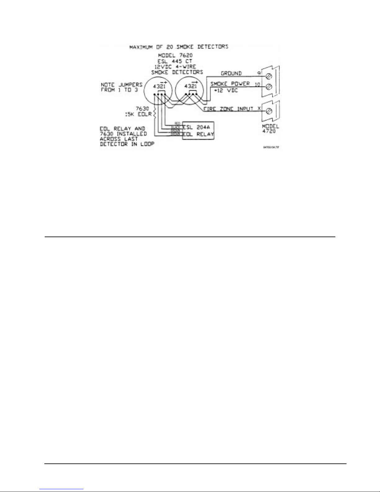
Regency® Model 4720 Control/Communicator Installation Manual (P/N 150476, Rev. A) Revised 10/98
Figure 9.2a: ESL 445AT Smoke Detector Wiring
9.3 Model 7181 Fire Zone Converter
The Model 7181 Fire Zone Converter allows you to connect style A (formerly class B) sensors to the Model
4720's style D (formerly class A) zones, to connect style D sensors to the Model 4720's style A zones, and
to connect 2-wire smoke detectors to the Model 4720's 4-wire zones. For installation information, see the
Model 7181 Installation Manual (P/N 150632).
10 Local Annunciation
10.1 Fire Bell Wiring with the Model 4160 Supervised Bel l Module
The Model 4160 Supervised Bell Module is required for Local Fire Alarm (NFPA 72 Local Protective
Signaling Systems, UL 864) installations. You MUST use a Wheelock 46T.G10 Polarized Bell with this
module. Follow the directions below to install the Model 4160.
Note: The Wheelock Model 46T.G10 will provide 85 dB at 10 feet.
1. Attach a 15-kΩ end-of-line (EOL) resistor (Model 7630) across the coil of the last bell in the loop.
2. Wire the negative (–) side of the bell(s) to Terminal 4 of the Model 4160.
3. Wire the positive (+) side of the bell(s) to Terminal 3 of the Model 4160.
4. If the bo ard has a shu nt bl ock, move it to the left (“out”) po s iti on . I f there is no shunt block, cut jumpe r
J1 on the Model 4720 control panel.
5. Connect Terminal 7 of the Model 4720 to Terminal 2 of the Model 4160.
6. Connect Terminal 5 of the Model 4720 to Terminal 5 of the Model 4160.
7. Connect Terminal 6 of the Model 4720 to Terminal 6 of the Model 4160.
8. Connect Terminal 1 of the Model 4160 to any unused zone of the Model 4720.
Note: The zone must be programmed as normally open, 24-hr. Supervised. This zone MAY NOT be used as an
alarm input.
33
Page 44
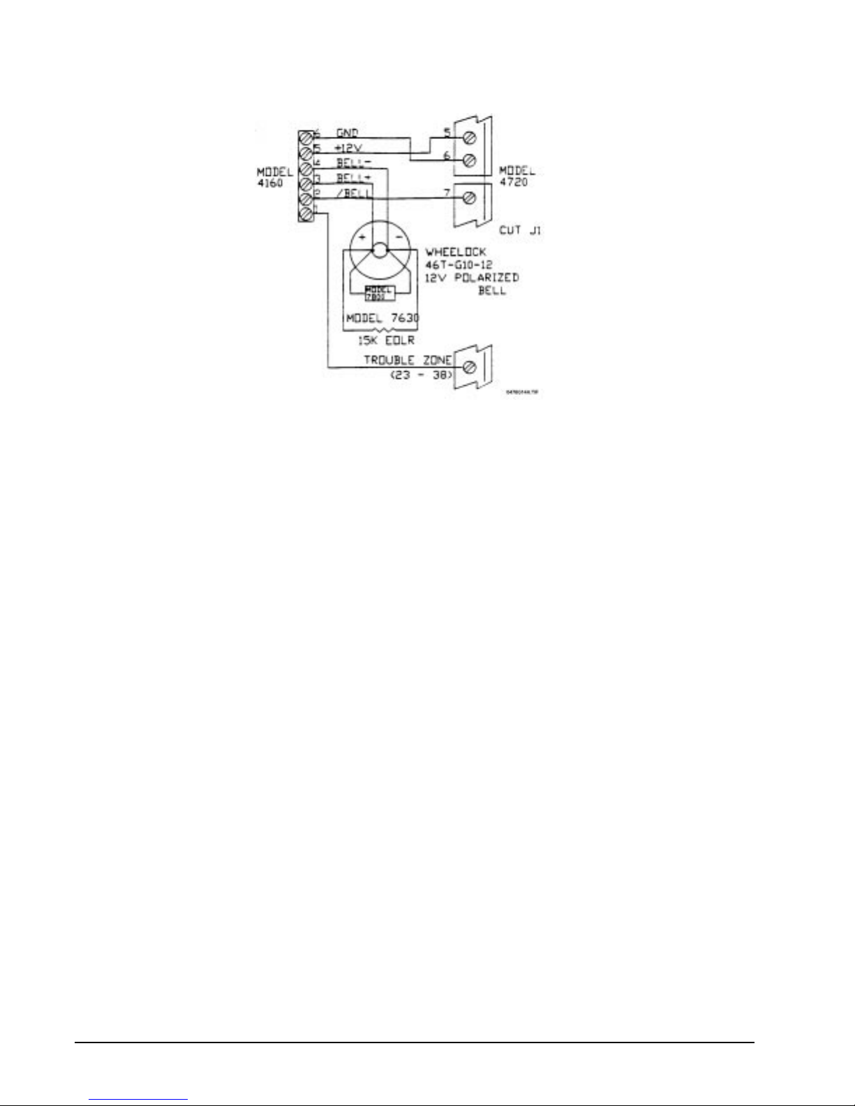
Regency® Model 4720 Control/Communicator Installation Manual (P/N 150476, Rev. A) Revised 10/98
See Table 4.1.1.0a (Section 4.1: Current Draw Calculations) for current rating.
Figure 10.1a: Model 4160 Supervised Bell Module Wiring
10.1.1 Auxiliary Power for Supervised Bells
The maximum bell current draw from Terminal 5 of the Model 4720 is 375 mA for NFPA 72 Local
Protective Signaling Systems, UL 864 installations. This equates to three (3) bells maximum (125
mA each). Additional bells can be used if the system includes the Model 4195 Auxiliary Power
Supply. The Model 4160 must be Revision D.2 or later (fused at 1.5 A FB). Connect Terminal 5 of
the Model 4160 to Terminal 3 or 4 of the Model 4195, instead of Terminal 5 of the Model 4720. The
maximum bell current is now 1 A (8 bells at 125 mA each). (Expected availability date of Revision
D.2 of the Model 4160 is 7/92.)
34
Page 45
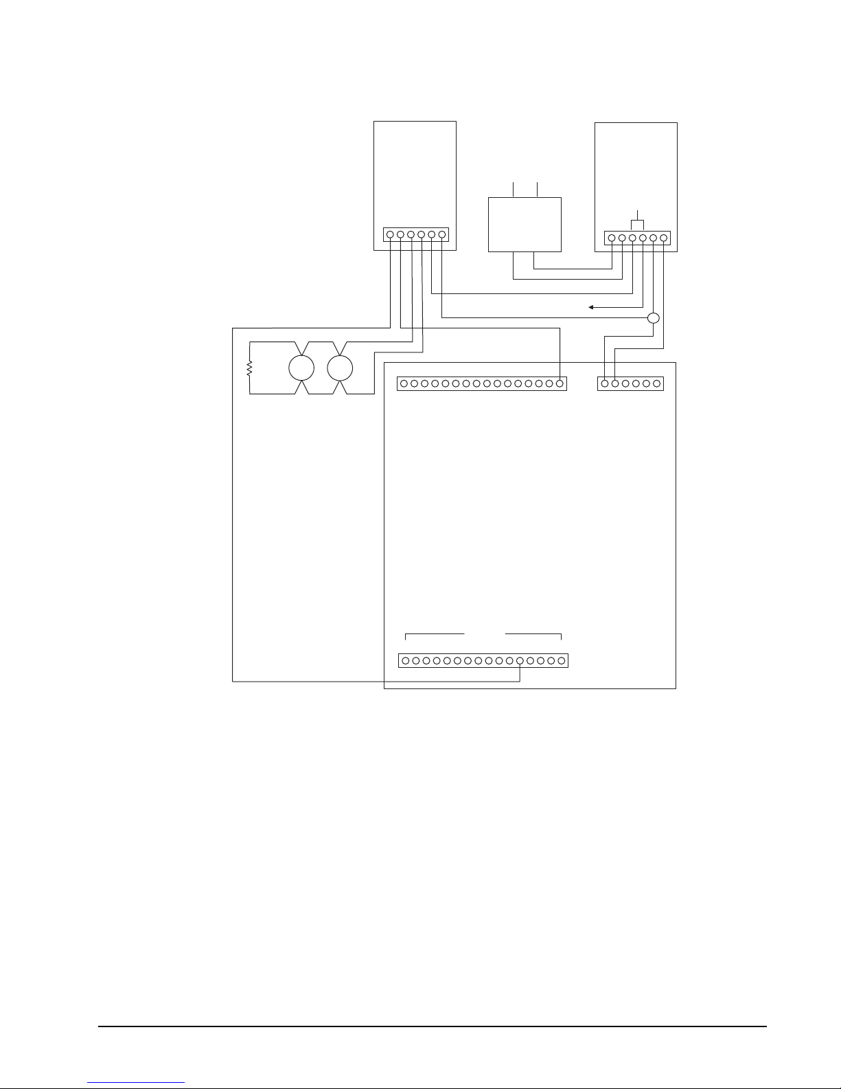
Regency® Model 4720 Control/Communicator Installation Manual (P/N 150476, Rev. A) Revised 10/98
MODEL 7630
EOL RESISTOR
SUPERVISION
+
_
BELLS
(1A MAX TOTAL)
+
_
4160
1 6
+12 V
GND
22 7
AC
9227
18 VAC
4720
4195
1.25 A EACH
1 6
+12 V
+12 V
6 1
23
ZONES
*TERM. 34 (ZONE 12) USED AS AN EXAMPLE
34*
38
0476G15A.DSF
Figure 10.1.1a: Auxiliary Power for Supervi sed Bells
10.2 Commercial Burglary Bell Wiring
Figure 10.2a shows the wiring of an external DC alarm bell. If you use a DC bell, you must either move the
shunt block to the left (“out”) position or, if there is no shunt block, cut the jumper labeled “J1” on the PC
board. You must also install the supplied transient suppressor Model 7800 as close as possible to the bell
contacts.
Note 1: When used in a UL Grade A Mer cantile (UL 36 5), Grade A Local (UL 6 09) or Grade B Cen tral Statio n (UL
1610) installation, an external alarm bell must be enclosed in UL Listed cabinet with tamper switches. The
AB-12 Bell and Housing manufactured by Ademco is UL approved for this purpose.
Note 2: CFM listed systems require one (1) listed audible driver to be installed inside the residence.
35
Page 46
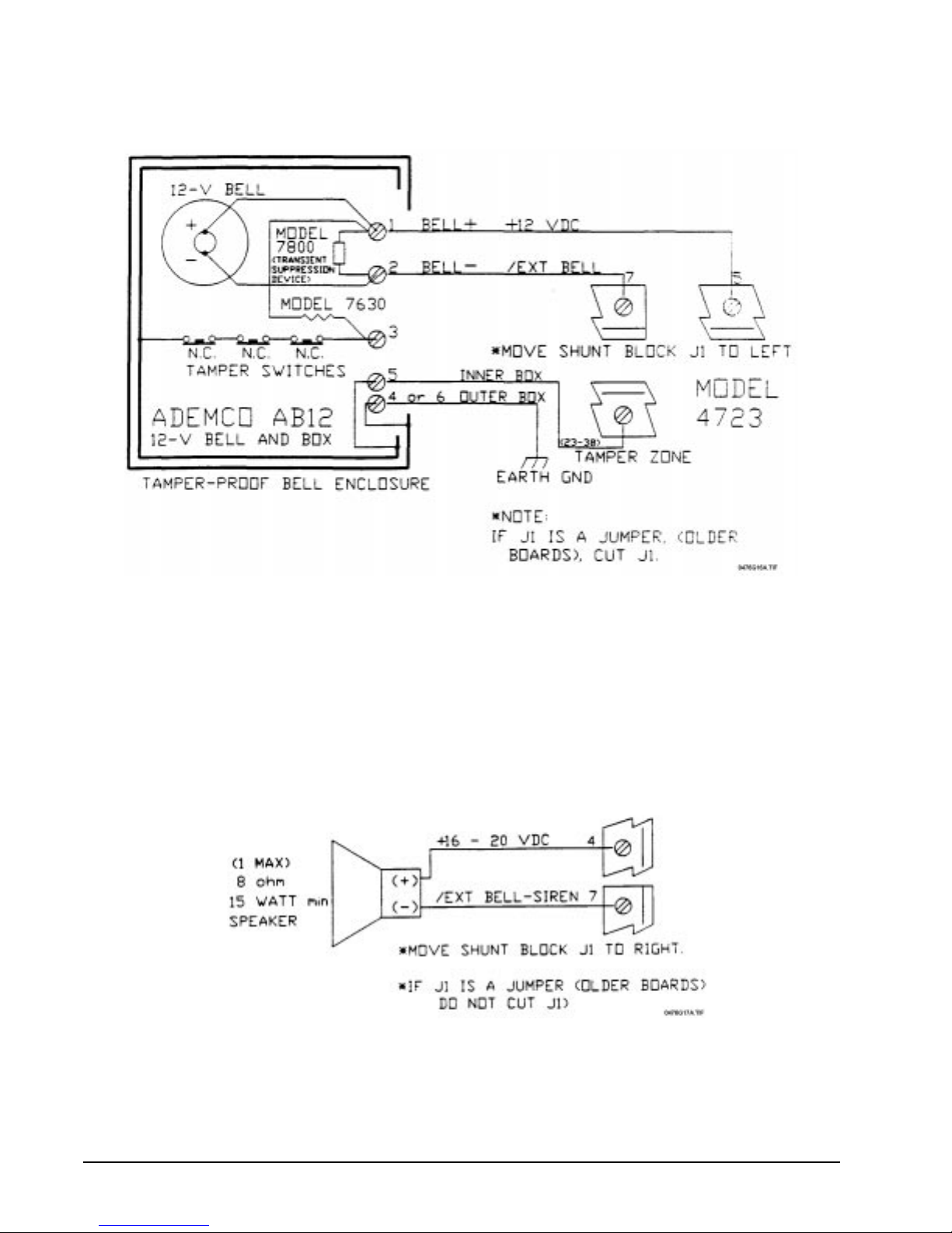
Regency® Model 4720 Control/Communicator Installation Manual (P/N 150476, Rev. A) Revised 10/98
Figure 10.2a: Commercial Bell Wiring
10.3 External Speaker Wiring
Terminal 4 (Ext. Spkr.) of the Model 4720 is designed for use with an 8-Ω, 15-W speaker. Connect the
speaker between Terminals 4 and 7 as shown in the diagram below. DO NOT cut Jumper J1 on the Model
4720. If the board has a shunt block, leave it in the right (“in”) position. An external speaker is NOT
permitted for UL commercial installati ons. It is onl y permitted in U L Residential installat ions. The Ad emco
713 is a suitable UL Listed speaker.
Figure 10.3a: External Speaker Wiring
36
Page 47
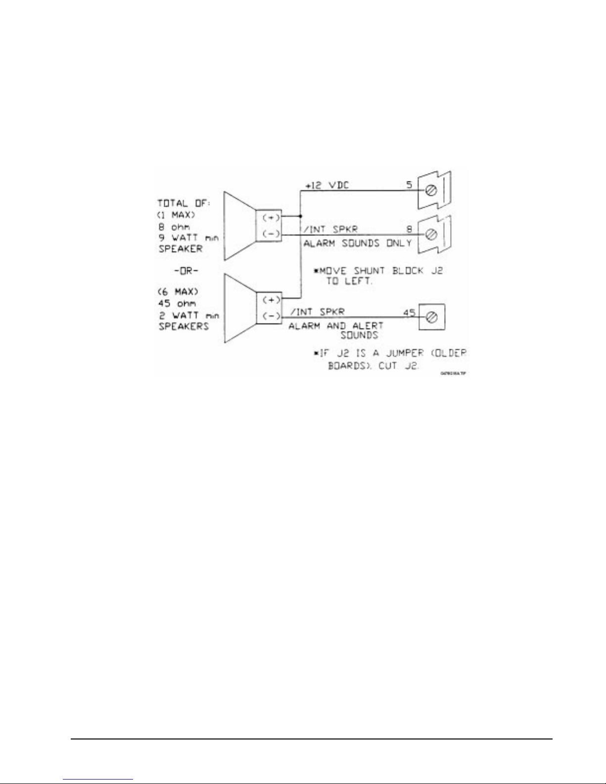
Regency® Model 4720 Control/Communicator Installation Manual (P/N 150476, Rev. A) Revised 10/98
10.4 Internal Speaker Wiring
If an internal speaker is to be used such as in a touchpad, it must be connected between Terminal 5
(auxiliary power, speaker +) and Terminal 8 (speaker –). The 4720 was design ed for use with an 8-Ω, 9-W
internal speaker or up to six 45-Ω, 1-W speakers.
If you wish to have alarm sounds only on some speakers, then cut Jumper J2 (move shunt block to the left/
“out” position). After doing so, speakers connected to Terminal 8 will produce alarm sounds only, but
speakers connected to Terminal 45 will still produce both alarm and alert sounds.
Figure 10.4a: Internal Speaker Wiring
10.5 Model 4180 Status Relays
See the Model 4180 Status Display Module Wiring Instructions (P/N 150445) for information on how to
install the Model 4180. Be sure to maintain a physical separation of at least one half inch between the field
wires and the Model 4180 connection points. This will prev ent transient damage to the Model 4180
connection points.
37
Page 48
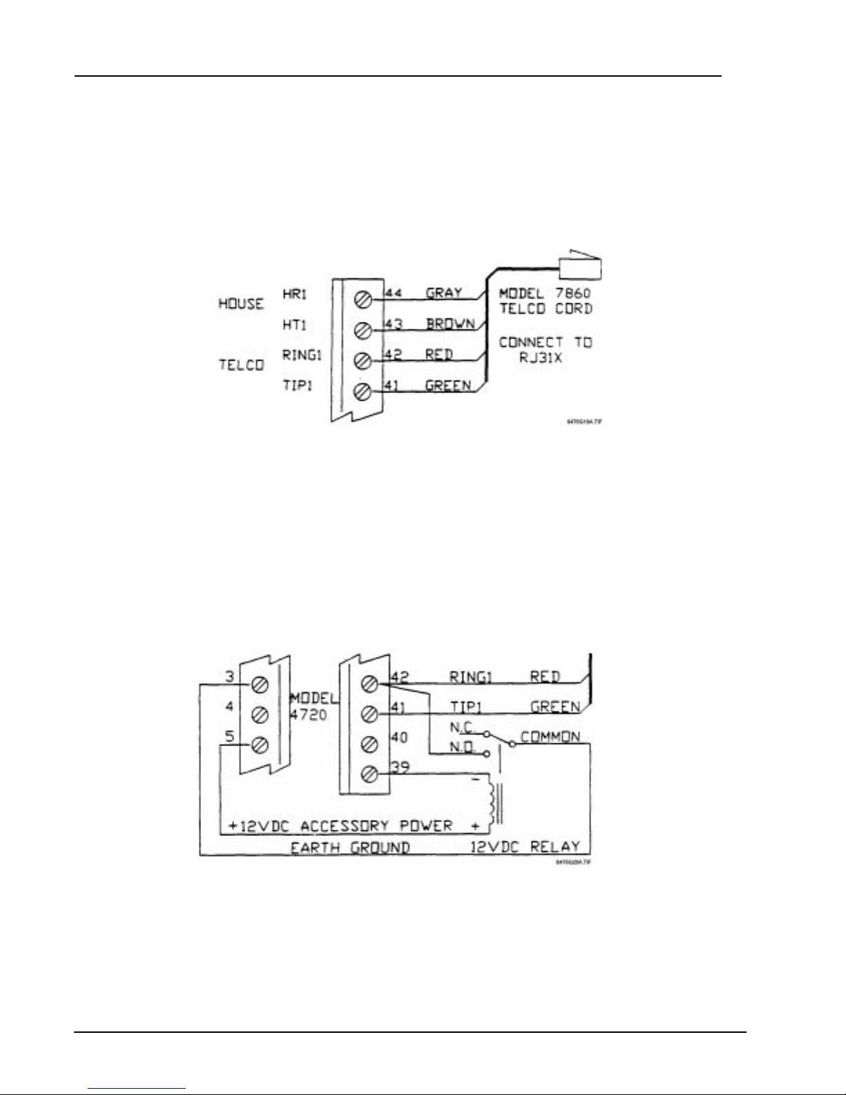
Regency® Model 4720 Control/Communicator Installation Manual (P/N 150476, Rev. A) Revised 10/98
11 Telephone Line Connection
11.1 Line 1 Wiring
The Model 4720 communicates to the cent r al s tation over the same telephone line a lr eady installed in your
home or building. You should connect the Model 4720 to the phone line using an RJ31X type phone jack.
The telephone company will install an RJ31X jack upon request. The Model 7860 connecting cord will
mate to the RJ31X and can be wired into the Model 4720 as shown in Figure 11.1a below.
Figure 11.1a: Telephone Line Wiring
11.2 Ground Start Relay Wiring
The Model 4720 normally communicates to the central station over standard “loop start” telephone
networks. In some instances, it may be necessary to communicate over “ground start” telephone networks.
Ground start networks require a momentary connection between one side of the telephone line and earth
ground to enable dial tone. The Mo del 4720 w ill accommoda te ground start trunks with th e addition of a 12
V
relay . Figure 1 1.2a shows the wiring of the Ground Start Relay. If you use the Ground Start feature you
DC
must select it when programming the EEPROM.
Note: In a UL installation, a ground start telephone network may not be used because it cannot be supervised.
Figure 11.2a: Ground Start Relay Wiring
38
Page 49
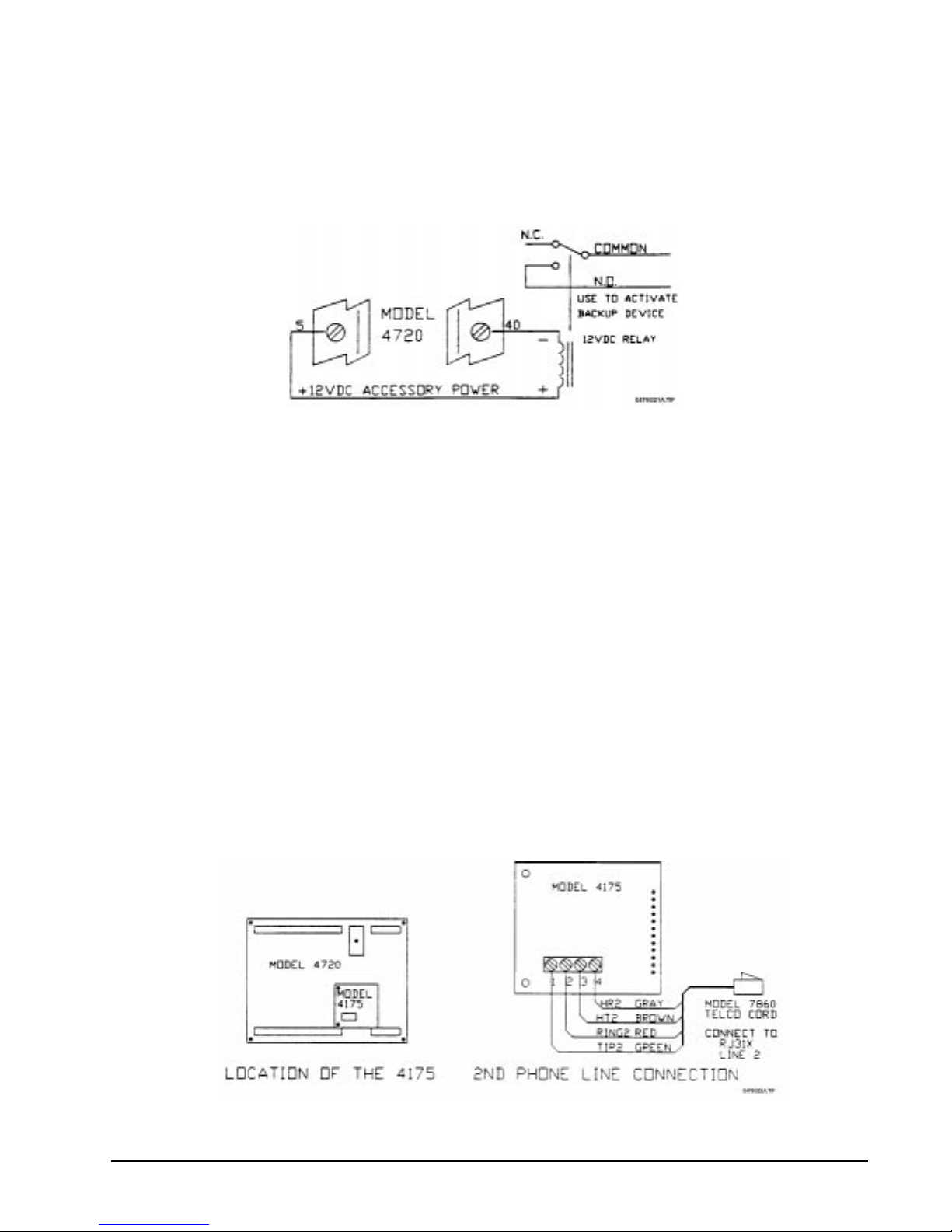
Regency® Model 4720 Control/Communicator Installation Manual (P/N 150476, Rev. A) Revised 10/98
11.3 External Dialer Failed Indicator
A 12-V
device such as an indicator lamp or the coil of a 12-VDC relay may be wired as a dialer failed
DC
indicator. To use a dialer failed indicator, connect the positive side of the indicator to Terminal 5 (auxiliary
power) and the negative side to Terminal 40 (dialer failed).
In UL applications, this signal is provided from the touchpads.
Figure 11.3a: Wiring for External Dialer Failed Indicator
11.4 Model 4175 Dual Phone Line Monitor with Ring Detector
11.4.1 Model 4175 Wiring
When using two (2) phone lines, you must install the Model 4175 Dual Phone Line Monitor.
The following notes apply to Revision L and later printed circuit boards:
Note 1: Before you can connect the Model 4175, y ou must remove Jump er bloc ks J5 and J6 from the Model
4720 board.
Note 2: When the Model 4175 is being used, the Answering Machine Bypass feature is NOT available.
Therefore, if an answering machine is installed, you must put it on Line 2. Downloading takes place
on Line 1, and an answering machine on Line 1 would prevent activation of the downloading
feature.
1. Plug the Model 4175 onto the Phone Line Monitor connector on the Model 4720 printed circuit
board (same connector as for the Model 4170).
2. Connect the second phone cord as shown in Figure 11.4a below. (The first phone cord for Line 1
should be connected directly to the Model 4720 as described in Section 11.1.)
Figure 11.4a: Wiring for Model 4175 Dual Phone Line Monitor
39
Page 50

Regency® Model 4720 Control/Communicator Installation Manual (P/N 150476, Rev. A) Revised 10/98
11.4.2 Model 4175 Operation
The 4720 will always try to use Phone Line 1 unless it is bad. If Phone Line 1 is bad, the Model
4720 automatically chooses Line 2. If the Model 4720 fails to communicate on its first attempt (on
either line), it will automatically switch to the alternate phone line. It will repeat this sequence until
it reaches a receiver or the total number of attempts (chosen during programming) is exceeded.
12 Expansion Zones
Note: Do NOT program 24-hour expansion zones as entry delayed. The reason is that 24-hour zones selected as entry
delayed do not bypass correctly during the entry time or when they are in alarm.
12.1 Model 4110 Zone Expander
The Model 4110 is a serial 2-wire zone expander that must be used in conjunction with the Model 4100 or
4101 SmartSensors. Using the Model 4110 can add up to 60 expansion zones to the Model 4720. The 4110
has two (2) separate serial loops and each loop can have up to 30 sensors. The sensors can be programmed
for normally open or normally closed contacts. The 4110 looks at individual sensor pairs (one on each loop)
to determine if an alarm condition is present. Each sensor in the loop gets its own identification number.
The 4110 must be mounted inside of the Model 4720 cabinet.
Note: This device can be used in burglary applications only, and must be connected with shiel de d c ab le with one
end of the shield connected to ground (Terminal 6) and the other end left unconnected. Wire gauge must be
18 (or larger). Maximum wire length is 1000 feet.
To connect the Model 4110 to the Model 4720, follow the steps below:
1. Sli de the Model 4110 printed circuit board into the plastic board mount located ins ide of the Model
4720 cabinet. Make sure that the terminal screws and 12-pin connectors are positioned towards the
Model 4720 PC board.
2. Connect one end of the 12-wire conductor to either one of the 12-position polarized connectors on the
Model 4110.
3. Connect the other end of the 12-wire conductor to one of the 12-position polarized connectors labeled
XBUS on the Model 4720. Run the 12-wire conductor around the Model 4720 PC board. Do NOT run
the conductor over or under the PC board.
4. If y ou will be using another model th at must be connected to the XBUS bus on the Model 4720, it may
be connected to the extra 12-position connector on the Model 4110.
12.1.1 Connecting the SmartSensors
Figure 12.1.1a shows how the two (2) serial loops are connected to the Model 4110. Wiring runs
should not exceed 1000 ft. For UL installations, each loop must be run in a separate 2-wire cable to
eliminate interference. If you use shielded cable, connect one end of the shield to circuit ground
(4720 Terminal 6), and leave the other end disconnected.
CAUTION:
To avoid equipment damage,
ALWAYS
observe correct
polarity when wiring the SmartSensors.
40
Page 51
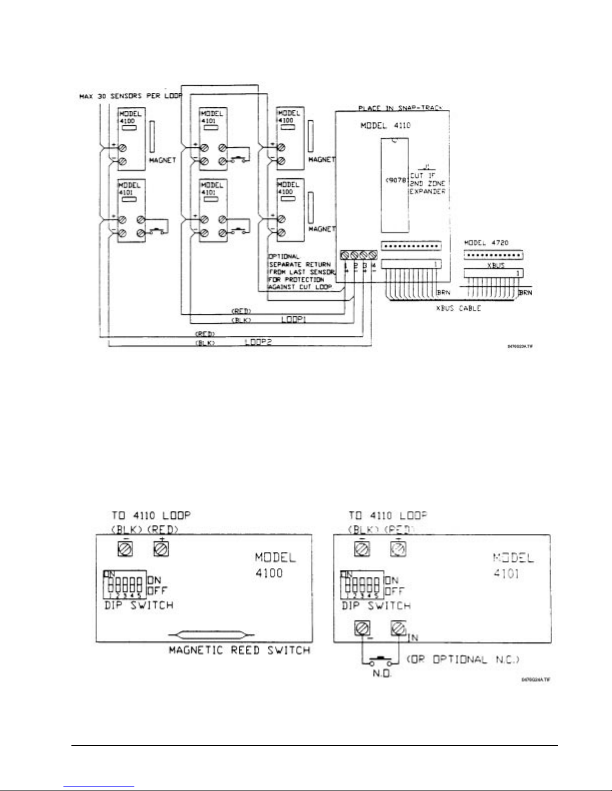
Regency® Model 4720 Control/Communicator Installation Manual (P/N 150476, Rev. A) Revised 10/98
Figure 12.1.1a: Wiring the Model 4110 Serial Zone Expander
The Model 4100 SmartSensor contains a magnetic reed switch for sensing alarms. The Model 4101
provides two (2) terminals for connecting either normally open or normally closed contacts. Both
models provide two (2) terminals for connection to the Model 4110 Zone Expander.
Note: When using the Model 4100 SmartSensor, you must choose the normally closed option for that
particular zone.
Figure 12.1.1b shows the Models 4100 and 4101 SmartSensors.
Figure 12.1.1b: Wiring the Models 4100 and 4101 SmartSensors
41
Page 52

Regency® Model 4720 Control/Communicator Installation Manual (P/N 150476, Rev. A) Revised 10/98
The Model 4110 has two (2) serial loops. Each loop may have up to 30 Model 4100 and Model
4101s in any combination. If you will be using 30 sensors or less, they should al l be place d on Loop
1 (Terminals 1 and 2 of the Model 4110). Terminal 1 is the positive terminal for Loop 1 and
Terminal 2 is the negative terminal for Loop 1.
Note: If you are using both serial loops on the Model 4110, DO NOT run both loops with the same
conductor (i.e., do not use a 4-conductor cable to run both loops). Separate conductors are required
to eliminate the possibility of “cross talk” between the two (2) loops.
1. Run a wire from Terminal 1 of the Model 4110 to the positive terminals on all of the Model
4100s and Model 4101s used in Loop 1 (maximum of 30 sensors).
2. Run a wire from Terminal 2 of the Model 4110 to the negative terminals on all of the Model
4100s and Model 4101s used in Loop 1 (maximum of 30 sensors).
Important: All positive terminals on the SmartSensors in a single loop must be connected together and all of the
negative terminals in a single loop must be connected together.
3. If more than 30 sensors are used, follow Steps 1 and 2 above but use Terminals 3 (positive) and
4 (negative) on the Model 4110.
You will notice that there are five (5) DIP switches on the SmartSensors (see Figure 12.1.1b). These
switches are used to select the sensor ID #. It is important that no two (2) sensors have the same ID
# in the same loop.
The SmartSensors are shipped with all switches in the ON position. The following chart shows
which switches to open (change to the OFF position) for specific ID #'s. The ID #s are NOT the
same as the zone numbers. This will be explained in Section 12.1.2.
On earlier revision sensors, five (5) jumpers are used instead of the five (5) DIP switches. Jumper 1
corresponds to Switch 1, Jumper 2 to Switch 2, etc. Instead of opening the switches, you would cut
the jumpers.
Table 12.1.1c: Switches to Open to Select Sensor ID Numbers
ID # SW1
(J1)
SW2
(J2)
SW3
(J3)
SW4
(J4)
SW5
(J5)
ID # SW1
(J1)
SW2
(J2)
SW3
(J3)
SW4
(J4)
SW5
(J5)
1 16 OFF OFF OFF OFF
2 OFF 17 OFF
3 OFF 18 OFF OFF
4 OFF OFF 19 OFF OFF
5 OFF 20 OFF OFF OFF
6 OFF OFF 21 OFF OFF
7 OFF OFF 22 OFF OFF OFF
8 OFF OFF OFF 23 OFF OFF OFF
9 OFF 24 OFF OFF OFF OFF
10 OFF OFF 25 OFF OFF
11 OFF OFF 26 OFF OFF OFF
12 OFF OFF OFF 27 OFF OFF OFF
13 OFF OFF 28 OFF OFF OFF OFF
14 OFF OFF OFF 29 OFF OFF OFF
15 OFF OFF OFF 30 OFF OFF OFF OFF
42
Page 53

Regency® Model 4720 Control/Communicator Installation Manual (P/N 150476, Rev. A) Revised 10/98
12.1.2 Determining ID Numbers and Zone Numbers
12.1.2.1 Calculating 4110 ID Numbers from Zone Numbers
To insure that the sensors activate the appropriate zones, you must assign the correct ID
numbers to the sensors. Zone numbers within the following range can be used with the
Model 4110 Zone Expander, if only one zone expander is used:
Lowest 4110 expansion zone # = Last internal zone # + 1
Highest 4110 expansion zone # = Last internal zone # + 60
The Last internal zone # is the number you entered in the Model 4720 Programmi ng Re cord
for the Last Int Z# option (see Section 9: Internal Zones). If you have not reprogrammed the
last internal zone, the factory-programmed value is 16.
Use the formula below to determine the ID number for each sensor:
Loop 1: ID # = (Zone # – Last internal zone #)
Note: If you get an ID # greater than 30, you must use Loop 2. Use the formula below to calculate
the ID #.
Loop 2: ID # = (Zone # – Last internal zone #) – 30
Example: If you are programming an ID number for a sensor that, when activat ed, will trigger an alarm
in Zone 49 (Loop 2), and your last internal zone was 13, the ID number would be determin ed
as follows:
ID # = (49 – 13) – 30
ID # = 6
12.1.2.2 Calculating Zone Numbers from ID Numbers
If you already know a sensor ID number and you need to determine which zone number is
displayed when that sensor is activated, use the following formula:
Loop 1: Zone # = ID # + Last internal zone #
Loop 2: Zone # = ID # + Last internal zone # + 30
12.1.3 Using Two Zone Expanders
When using two (2) zone expanders you must decide which expander will be 1 and which will be 2.
If the Model 41 10 is to b e 1, no mo dific ations nee d be made to the PC b oard. If the Mode l 4110 is to
be Expander 2, you must first cut Jumper J1 on the Model 4110 printed circuit board. When this is
done, the Model 4720 will see the Model 4110 as “Device 3” instead of “Device 2”. When using
software Revision 880911 or later, the zone numbers for the two (2) expanders are determined in the
same way (see Section 12.1.2: Determining ID Numbers and Zone Numbers).
CAUTION:
When the Model 4110 is being used as Expander 2, the zone
numbers selected must not overlap the zone numbers used on
Expander 1.
Total system zones (including internal zones , Expan der 1
zones and Expander 2 zones) may not exceed 80, regardless
of how many zone expanders are used.
43
Page 54
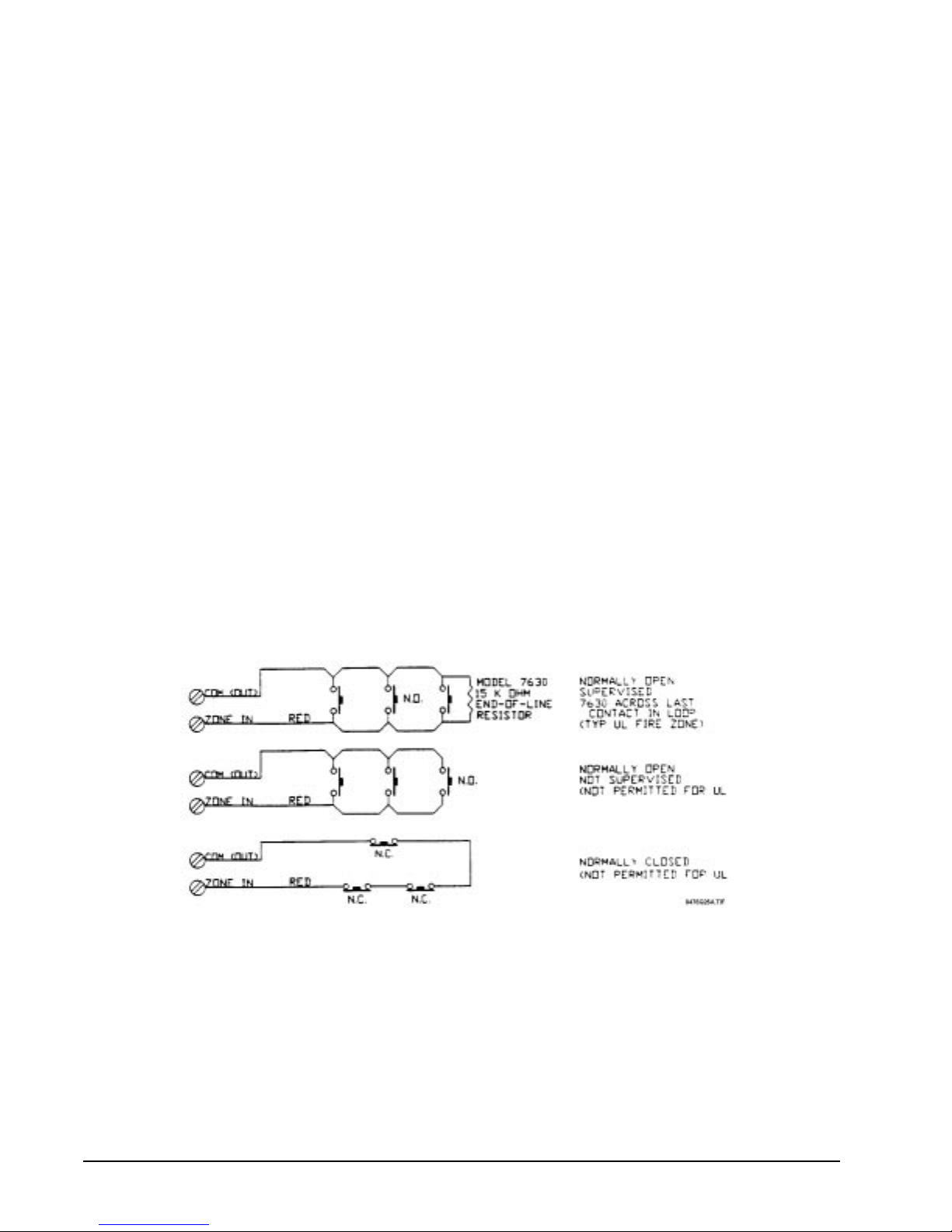
Regency® Model 4720 Control/Communicator Installation Manual (P/N 150476, Rev. A) Revised 10/98
12.2 Model 4115 Serial Zone Expander
The Model 4115 is a UL Listed 2-wire serial zone expander for the Model 4720/4724 Control/
Communicator that allows up to 64 switches to be connected on a single pair of wires.
The 12/91 Regency binder update contained a preliminary version of the documentation for the Model
4115. That documentation is now contained in a separate Model 4115 Installation Manual (P/N 150648)
which is shipped with the Model 4115.
12.3 Model 4125 Zone Expander
The Model 4125 is a multiplexed zone expander that can add up to 64 expansion zones to the Model 4720.
In any one zone, all contacts must be either normally open or normally closed. The Model 4125 is mounted
in a separate cabinet not excee ding thr ee (3) f t. from the ma in contr ol unit. The conn ection must be mad e in
conduit.
The 4125 provides 64 inputs and 32 outputs for connection of up to 64 zones. For each pair of input screws,
the two (2) input screws share the output screw (labeled COM) located between them.
Once the Model 4125 cabinet has been mounted near the Model 4720, connect one end of the 12-wire
conductor to the “XBUS” of the Model 4720. Connect the other end of the cable to the 12-pin connector on
the Model 4125.
Note: If another model is used that has an unused 12-pin expansion connector, the Model 4125 may be connected
to the unused location.
12.3.1 Model 4125 Zone Wiring
There are three possible ways to wire the zones on the Model 4125. Figure 12.3.1a shows the three
basic configurations (normally open, normally closed, and normally open Supervised).
Note: For UL Fire installations, each zone loop must be wired using 18-gauge wire (or larger). For UL
Burglary installations, wire must be 22-gauge (or larger). Maximum wire length is 1000 feet.
Figure 12.3.1a: Model 4125 Basic Zone Configurations
44
Page 55
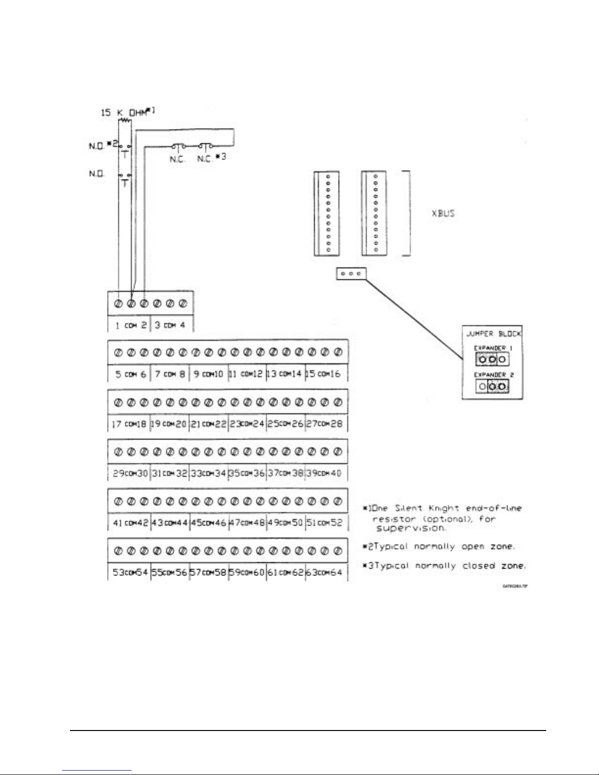
Regency® Model 4720 Control/Communicator Installation Manual (P/N 150476, Rev. A) Revised 10/98
Figure 12.3.1b shows how to wire the Model 4125 to a 4000 series control panel.
Figure 12.3.1b: Wiring the Model 4125 Zone Expander to a 4000 Series Control Panel
45
Page 56

Regency® Model 4720 Control/Communicator Installation Manual (P/N 150476, Rev. A) Revised 10/98
12.3.2 Determining 4125 Zone Expander's Input and Zone Numbers
Note: Output numbers are not calculated for the Model 4125 because the ou tputs are n ot numbe red—they
are labeled “COM”.
12.3.2.1 Calculating 4125 Input and Zone Numbers
The zone number is the number displayed on touchpads and reported to the central station.
The input number is the screw terminal number silk-screened on the Model 4125 PC board.
In order for the correct zone number to be displayed when a contact is activated, it is
necessary to determine the correct input numbers. Calculate the input number using the
following formula:
Input # = (Zone #) – (Last internal zone #)
The Last internal zone # is the number you entered in the Model 4720 Programmi ng Record
for the Last Int Z# option (see Section 9: Internal Zones). If you have not reprogrammed the
last internal zone, the factory-programmed value is 16.
12.3.2.2 Calculating 4125 Zone and Input Numbers
If you already know the input number of a contact, and you want to know which zone is
displayed when that contact is activated, use the following formula to calculate the zone
number:
Zone # = (Input #) + (Last internal zone #)
12.3.3 Using Two Zone Expanders
First determine if the Mode l 4125 wi ll be E xpander 1 (Devi ce 2) or Expander 2 (Dev ice 3). I f it will
be Expander 1, no modifications need be made to the PC board. If the Model 4125 will be Expander
2, move the jumper block (located beside the 12-wire connectors labeled EXP) to the right.
When the Model 4125 is used with the Model 4720 (without the Model 4724 Control/Expander),
zone numbers and input numbers are calculated the same way as in Section 12.3.2. Begin wiring
Expander 2 at:
(Expander 1 last input #) + 1
When the Model 4125 is used with the Model 4724 Control/Expander, zone numbers and input
numbers are calculated as follows:
Input # = Zone # – (Last Expander 1 zone #) – (Last internal zone #)
Zone # = Input # + (Last Expander 1 zone #) + (Last internal zone #)
12.4 Model 4130 Zone Expander
12.4.1 Installing the Model 4130
The Model 4130 is an RF (Radio Frequency) zone expander. This module mounts inside of the
Model 4720 cabinet and is then connected to the Model 4135 Remote Receiver. This expander can
provide up to 64 additional zones to the Model 4720. Each RF transmitter becomes a separate zone
which reports to the remote receiver. The 4135 receiver communicates to the Model 4130 via a 4wire cable with a wire gauge of 22 (or larger), up to 500 feet in length, allowing placement of the
Model 4135 for optimum RF reception.
Note: Any combination of two (2) zone expanders may be used on the Model 4720 but the maximum
number of zones (Including touchpad panic switches) cannot exceed 83.
46
Page 57
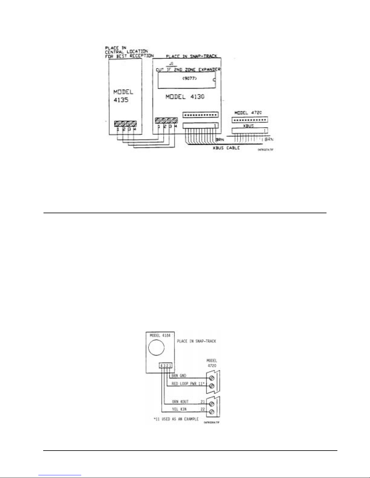
Regency® Model 4720 Control/Communicator Installation Manual (P/N 150476, Rev. A) Revised 10/98
Figure 12.4.1a: Wiring the Model 4130 RF Zone Expander and Model 4135 Remote Receiver
12.4.2 Programming the Transmitters
See the Model 4130/35 Installation Manual (P/N 150474).
13 Model 4184 Watchdog Module
13.1 Model 4184 Watchdog Module Wiring
The Model 4184 Watchdog Module connects to the Model 4720 Control/Commun icator in order to co mply
with NFPA commercial fire protection equipment standards.
NFPA Standards require that all equipment trouble conditions must be reported. The Model 4184 Watchdog
Module monitors failures of all touchpads or failures in the control micro control unit, as the touchpads
themselves cannot annunciate these types of malfunctions.
The Model 4184 operates by monitoring the data from the touchpads. The control polls each touchpad
every 70 seconds. If the data signal fails for any reason, the Model 4184 will time out and begin emitting a
steady tone until the signal is restored. The audible signal from the Model 4184 Watchdog Module cannot
be silenced.
Figure 13a: Model 4184 Watchdog Module Wiring
47
Page 58

Regency® Model 4720 Control/Communicator Installation Manual (P/N 150476, Rev. A) Revised 10/98
The Model 4184 Watchdog Module is installed in the Snap-trak, and connects to the Model 4720 control
communicator through a 4-conductor cable (P/N 130235) in the following manner:
Wire Color 4720 T ermina l
Brown 9 (circuit ground)
Red 11, 12, 13, 14 (loop power)
Orange 21 (serial data touchpads)
Yellow 22 (serial data from touchpads)
13.2 Operating Procedure, 4184 Watchdog Module
If a short or open should develop in touchpad power (Terminal 20 or Fuse F2), the LCD will go blank. The
Model 4184 Watchdog Module will start its audible alarm within two (2) minutes of this event.
If a short or open circuit should develop in the data flow to the touchpads (Terminal 21), the LCD will not
change its displayed information. In this situation, the Control/Communicator will reset the touchpads
within 70 seconds. A single letter will appear, and all LEDs will be turned on. The 4184 Watchdog Module
will start its audible alarm at this moment.
If a short should occur in the data from the touchpads (Terminal 22), the following events will occur. The
Model 4720 Control/Communicator will reset the touchpads every four (4) seconds. This will cause the
LEDs to flash and an audible signal will be h eard. The Mode l 418 4 Watchdog Module will not be activa ted.
If an open condition should occur in the data flow from the touchpads (Terminal 22), the following events
will occur. The Control/Communicator will reset the touchpads within 70 seconds. A single letter will
appear on the touchpads and all LEDs will be on. The audible alarm will beep once. The Model 4184
Watchdog Module will begin emitting its audible alarm within the next two (2) minutes.
If a failure should develop in the control MCU, the Model 4184 Watchdog Module will start emitting its
alarm within two (2) minutes.
14 Other Expansion Devices
14.1 Model 4140 Intercom/Telephone Controller
The Model 4140, when used with Model 4640 Audio Module, is a hands-free telephone and intercom
system. This system operates in a half-duplex mode, meaning that only one party can talk at a time. The
Model 4140 uses complex circuitry to de tec t when each p arty is att empti ng to talk . It t hen sw itches th e talk
direction to the party meeting the criteria esta blished by the Model 4140.
As a general rule, the party with the highest audio level will have control of the talk path. This is why
hands-free systems, such as the Model 4140, do not function well in high noise environments.
The 4140 must be mounted within three (3) feet of the Model 4720.
48
Page 59
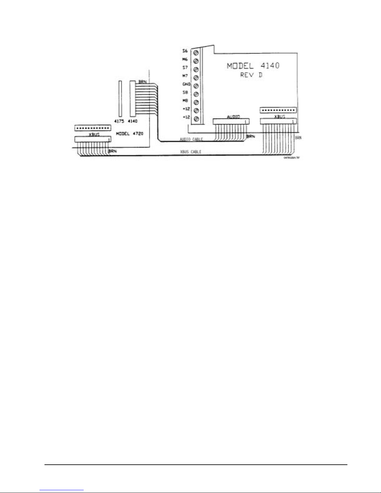
Regency® Model 4720 Control/Communicator Installation Manual (P/N 150476, Rev. A) Revised 10/98
Figure 14.1a: Connecti ng the Model 4140 to the Model 4720
14.1.1 Mounting the Model 4640
The Model 4640 is designed to be mounted next to a touchpad at its right side. The plastic prongs
sticking out of the Model 4640 are for attachment to a touchpad.
To mount:
1. Remove the touchpad's back plate.
2. Remove the hidden alignment notch on the right side of the touchpad plate. Use side-cutters to
make cuts in the grooves on the notch. Move the cut notch back and forth a few times. It should
break off easily. If necessary, use a knife to clean off any excess plastic.
3. Slide the Model 4640's prongs into the indentation you made on the touchpad. Secure the Model
4640's back plate to the wall using pan head screws. Pull wires through the indentation in the
back plate of the Model 4640. Snap the front plate firmly, being careful not to pinch the wires
between the front and back pl ates.
49
Page 60
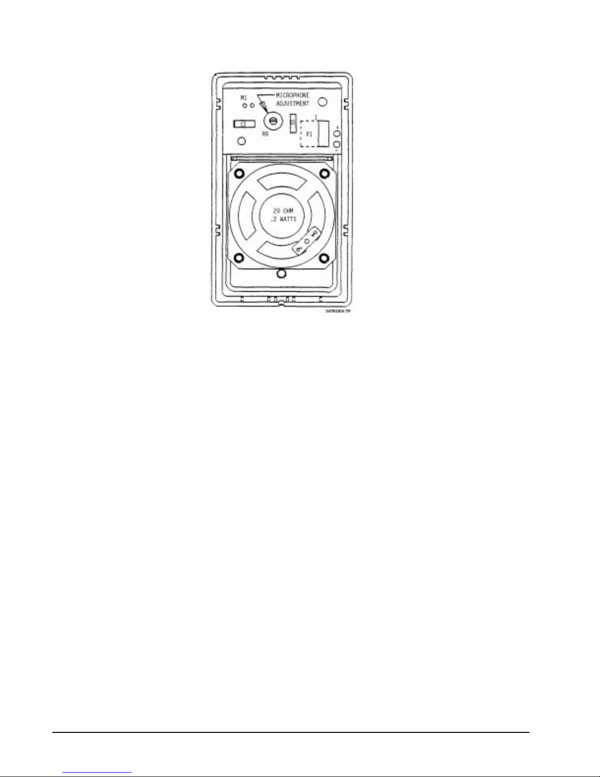
Regency® Model 4720 Control/Communicator Installation Manual (P/N 150476, Rev. A) Revised 10/98
Figure 14.1.1a: Model 4640 Audio Module
14.1.2 Mounting the Model 4640 as a Stand-Alone Intercom
If the Model 4640 will never need to be attached to a touchp ad, t he pla stic prongs on t he lef t side of
the module can be removed. Move the prongs back and forth a few ti mes. They should break off
easily.
Secure the back plate of the Model 4640 to a w all using pan head scre ws only. Pull wires through the
indentation in the back plate of the Model 4640. Snap the front plate firmly, being careful not to
pinch the wires between the front and back plates. A 4640 module can be mounted up to 1,000 feet
from its controlling unit.
14.1.3 Connecting the Model 4140 to the Model 4640 Intercom Station
To connect the Model 4140 to the Model 4640 you must use a 3-conductor shielded cable. Table
14.1.3a shows how to connect the Model 4640. The 4640 is shipped with an 8-inch detachable cable
(P/N 130375). You can connect the Model 4640 as any station number from 1 to 8. The digits
following the letters S and M indicate which station number you are wiring on the Model 4140.
Use 18-gauge wire with a maximum length of 1000 feet. Connect Pins 1 and 5 to the shield of the
field wiring. Note that the letter “X” after the terminals S and M refers to inputs 1-8.
On 4140 boards prior to Revision D, Pin 2 of the Model 4640 must be wired to Terminal 5 on the
Model 4720. On boards prior to Revision E.2, the microphone gain adjustment on the Model 4640
may have to be adjusted to minimum gain. This will prevent system oscillations, but will also reduce
the volume of the microphone. (To identify which revision you are using, refer to the white sticker
on the board. It's usually located in the top left corner.)
50
Page 61
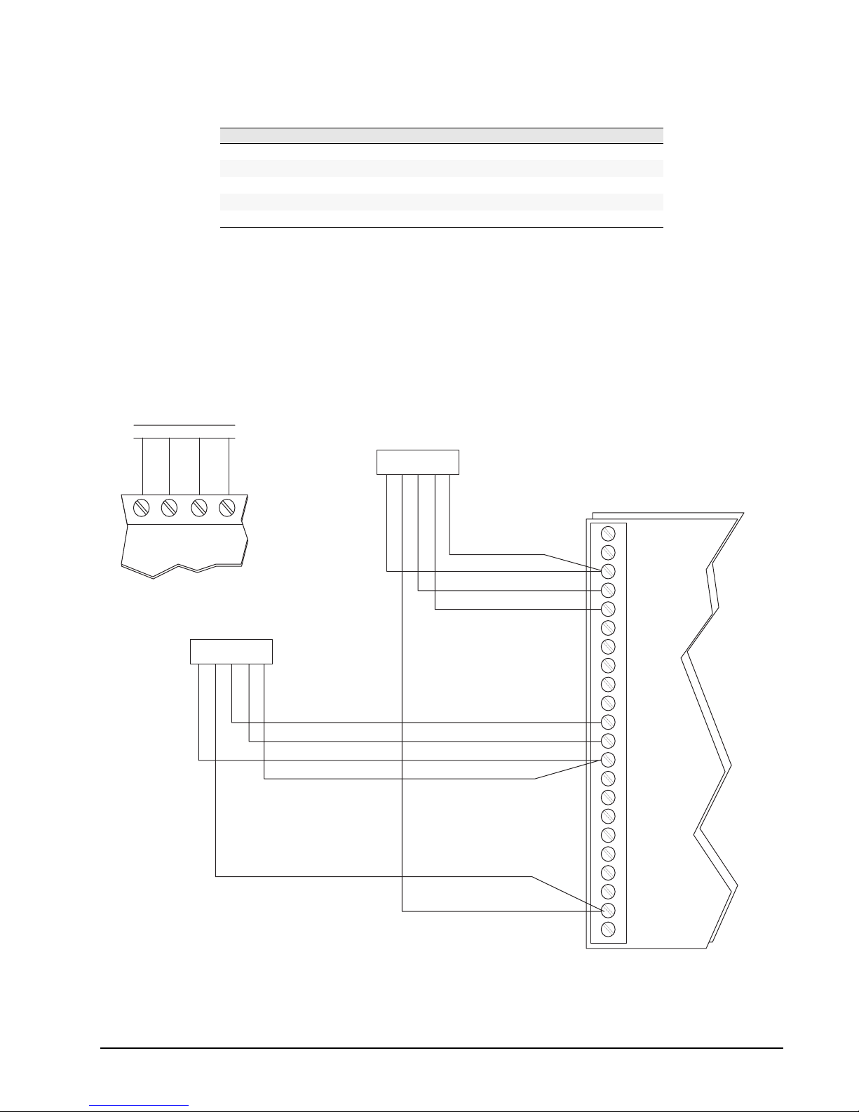
Regency® Model 4720 Control/Communicator Installation Manual (P/N 150476, Rev. A) Revised 10/98
Table 14.1.3a: Connecting the Model 46 40
4640 Pin # 4140 Terminal # Description Wire Color
1
2
3
4
5
GND Ground Black
+12 VDC Auxiliary power Brown
+SX Speaker signal (+) Green
MX Microphone signal White
GND Speaker signal (–) Red
The Model 4640 has a microphone gain adju stmen t lo cated on th e bac k of the u nit . It can b e used t o
reduce the microphone gain if backgro und noise at th e remote cau ses the system to swi tch talk pa ths
incorrectly.
When adjusting the gain, b e sure to do yo ur f inal vo lu me che ck af ter t he Mode l 4 640 is moun ted o n
the wall. This is because the intercom may function differently when mounted on the wall than it
does when being held.
MODEL 4660
SERIES TOUCHPAD
4
3
21
MODEL 4640
4
215
3
22
21
MODEL 4720
20 19
MODEL 4640
(STAND-ALONE)
4
215
3
GRN
WHT
BLK
RED
BRN POWER
BRN
RED
BLK
WHT
SHIELD
SPEAKERGRN
MICROPHONE
SPEAKER
MICROPHONE
SHIELD
MODEL 4140, REV. D
S1
M1
GND
S2
M2
S3
M3
GND
S4
M4
S5
M5
GND
S6
M6
S7
M7
GND
S8
M8
+12
Figure 14.1.3b: Sample Model 4640 Connection
(Showing two 4640s: one connected at touchpad and one as stand-alone intercom)
0476G31A.DSF
51
Page 62
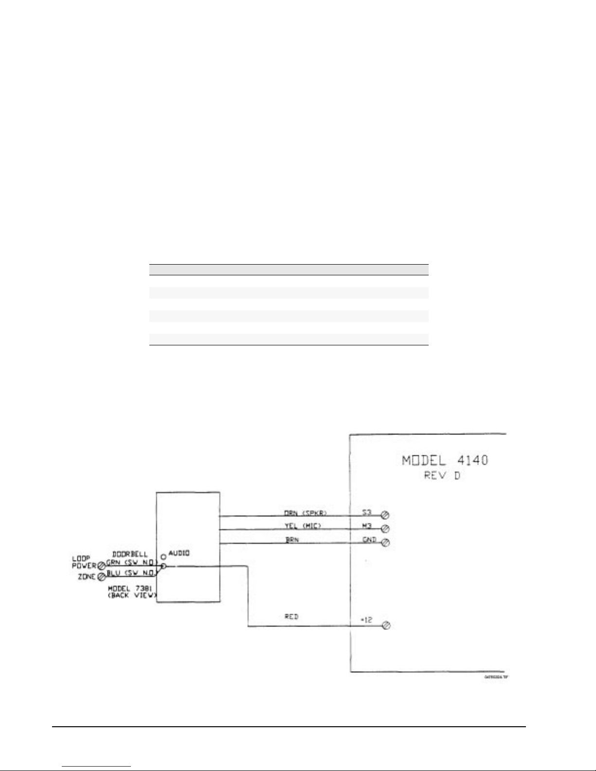
Regency® Model 4720 Control/Communicator Installation Manual (P/N 150476, Rev. A) Revised 10/98
14.1.4 7381 Connecting the Model 4140 to the Model 7381 Front Door Intercom Station
The Model 7381 is an outdoor intercom station intended for use with the Model 4720/4140 Control/
Communicator with Intercom.
The Model 7381 contains a microphone with amplifier, a 20-ohm speaker , a light used by visitors to
locate the unit and a normally open push-button switch.
The switch can be used to ring an existing doorbell/chime or wired to the control/intercom to
produce a door chime tone.
Note: While the Model 7381 is intended for outdoor use, it is NOT weatherproof and should not be
exposed directly to rain and/or snow. The 7381 operates in a temperature range of 0°C - 70°C (32°F
- 125°F).
Use 24-gauge grounded 3-wire shielded cable (three insulated wires, one bare wire and a foil wrap).
Wire run must not exceed 200 feet.
The contacts at the normally open switch are rated at 1 A, 24 V
T able 14.1.4a: Wiring Table
7381 Wire Color Model 4720 Model 4140
AC
.
Brown NC TERM (GND)
Red TERM 5 NC
Orange NC TERM S1
Yellow NC TERM M1
Green 4720 zone output*
Blue 4720 zone input*
* Note: If you are using the doorbell option with the Model 4720/4140, connec t the b lue wir e to th e inpu t of
the zone that has been programmed as the doorbell zone. Connect the green wire to its
corresponding output. Program this zone as NORMALLY OPEN, 24-HOUR, NOT SUPERVISED,
and DOORBELL TYPE.
Figure 14.1.4b: Connecting the Model 7381 to the Model 4140
52
Page 63
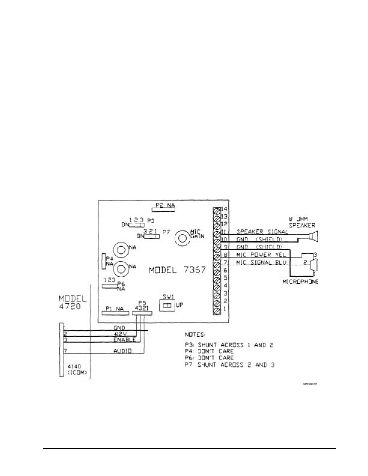
Regency® Model 4720 Control/Communicator Installation Manual (P/N 150476, Rev. A) Revised 10/98
14.2 Model 4150 Environment Control
See the Model 4150 Auxiliary Control Module Installation Manual (P/N 150475).
14.3 Printing Devices
14.3.1 Model 5255 On-Site Printer (Discontinued)
For 5255 installation instructions, refer to the Model 5255 Installation Manual (P/N 150296).
Note: The Model 5255 uses printer paper with the part number 005257. The LCD shows the message
PAPER when the printer runs out of paper.
14.3.2 Model 5260 Printer Interface
The Model 5260 Printer Interface attaches to the Model 4720 expansion bus to print activity reports
on a standard parallel or serial interface printer, or to send information to a serial comput er port. For
5260 installation instructions, refer to the Model 5260 Installation M anual (P/N 150591).
14.4 Model 7367 Two-Way Audio Listen-i n Module
Figure 14.4a shows how to wire the Model 7367 Two-Way Audio Listen-in Module using the supplied
microphone. Figure 14.4b shows how to wire the Model 7367 using the Model 4640 Speaker and
Microphone. Refer to the Model 7367 Installation Instructions (P/N 150572) for additional information.
Figure 14.4a: Model 7367 with Speaker and Supplied Microphone
53
Page 64
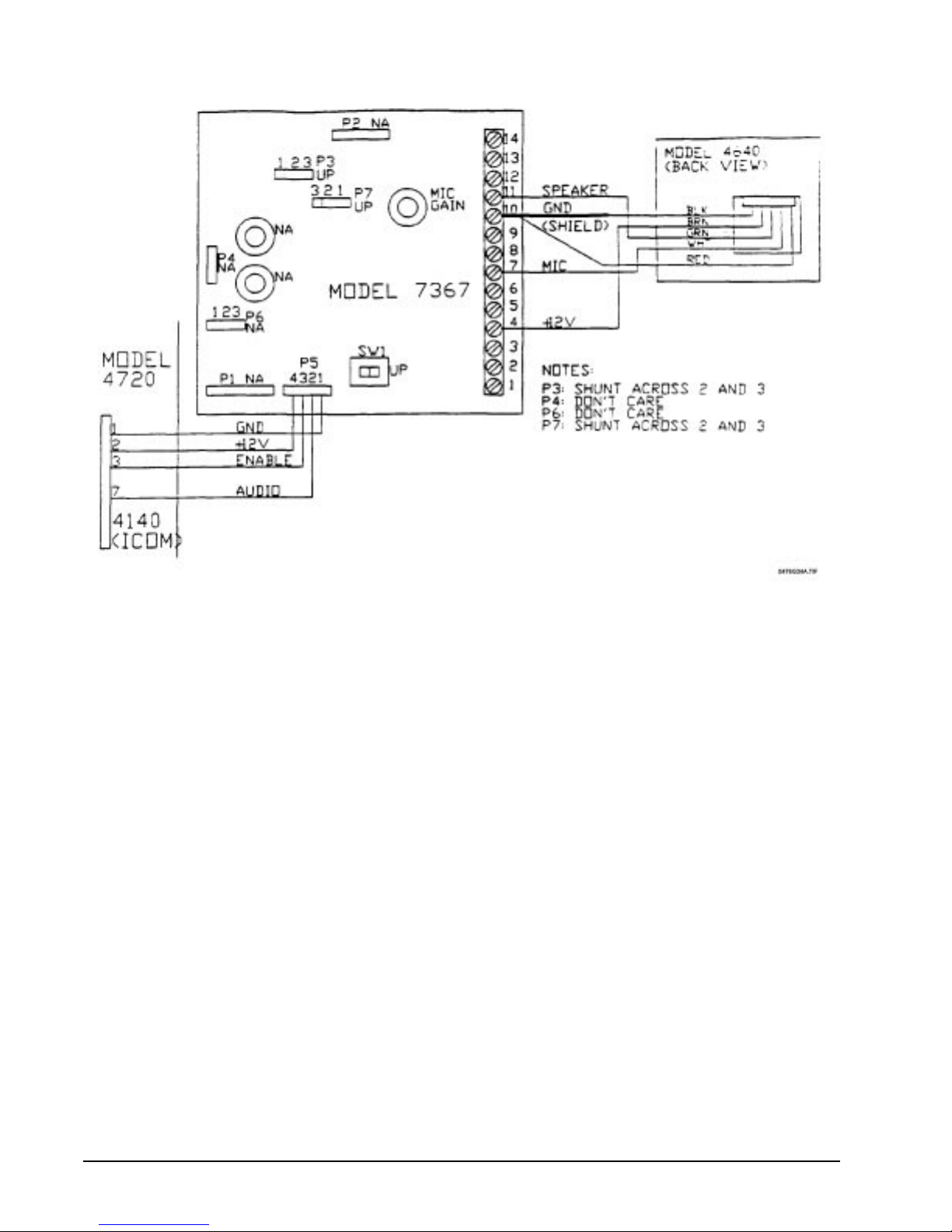
Regency® Model 4720 Control/Communicator Installation Manual (P/N 150476, Rev. A) Revised 10/98
Figure 14.4b: Model 7367 with Model 4640 Speaker and Microphone
14.5 Model 7369 Two-Way Audio Listen -in Module
The Model 7369 Two-Way Audio Listen-In Module allows for alarm verification and two-way
communication. Refer to the Model 7369 Installation Manual (P/N 150605) for more information.
54
Page 65
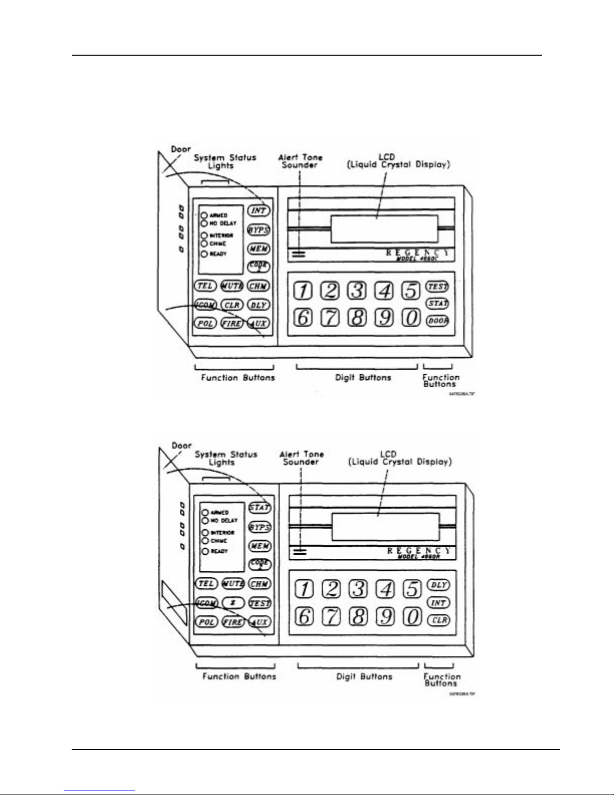
Regency® Model 4720 Control/Communicator Installation Manual (P/N 150476, Rev. A) Revised 10/98
15 Touchpad Operation
The following paragraphs describe the fu nctions of the ind icators and swit ches provided on the touchp ads. Keep in
mind that some of the touchpads do not provide all of the functions listed. If you are using a touchpad that does not
have a described function, skip that particular paragraph.
Figure 15a: Model 4660B/C Comm erci al Touchpad
Figure 15b: Model 4660R Residenti al Touchpad
55
Page 66

Regency® Model 4720 Control/Communicator Installation Manual (P/N 150476, Rev. A) Revised 10/98
15.1 LED Indications
15.1.1 LEDs on Left Side (Behind Door)
Armed LED
ON – The system is armed.
OFF – The system is disarmed.
FLASHING – One or more zones are in an alarm condition.
No Delay LED
ON – Zones that were programmed as delayed will now act as instant zones, with no delay
before generating an alarm.
OFF – Exit and entry delayed zones will work as programmed.
Interior LED
ON – All zones will be armed when the Armed light is ON.
OFF – Interior zones are disabled. When the Model 4720 is armed, it protects the building
against entry from the outside, but people can move around inside without setting off the
alarm.
Chime LED
ON – The 4720 is disarmed and the Chime feature is enabled. When anyone enters the
protected area via a zone programmed as a chime zone, a chime zone will sound.
OFF – SYSTEM DISARMED – The Chime feature is disabled. NO tone will sound when
anyone enters the protected area.
SYSTEM ARMED – When the system is armed, violating a zone w ill cause an alar m, NOT a
chime tone.
Ready LED
ON – The system is disarmed and all enabled zones are ready to be armed. (Zones that are
disabled have either been bypassed, or they are interior zones that have been turned off.)
OFF – This has two meanings:
FLASHING – The 4720 is reporting to the central station.
15.2 Audible Alarms
15.2.1 Touchpad Alert Tones
• Entry/Exit Warning – Single tone, half second on, half second off.
• Alarm – A short beep every three (3) seconds.
• Chime Zone Opened – Two (2) short beeps
SYSTEM DISARMED – One or more zones are in a Not Ready condition. A
sensored door or window may be open. The zone(s) that are in a not ready condition
will be indicated by the Zone LEDs.
SYSTEM ARMED – System is in normal operating condition.
56
Page 67

Regency® Model 4720 Control/Communicator Installation Manual (P/N 150476, Rev. A) Revised 10/98
The touchpad speakers will also beep when:
• A key is pressed.
• Someone has activated the zone display by pressing the BYPS, MEM, or STAT keys.
• The zone display has been activated by an alarm or zone tro uble conditi on (excep t silen t alarms).
• An incorrect keyswitch entry has been made. This tone is longer th an the other beeps . There may
be a delay before it is sounded.
15.2.2 Bell Sounds
• Fire Alarm Bell – A pulsing bell, sounded whenever there is a fire alarm (600 ms ON, 400 ms
OFF).
• Emergency (Non-medical) Alarm Bell – A slowly pulsing bell, sounded whenever there is an
audible panic, gas, undefined, water, heat, cold, or local auxiliary alarm (2 seconds ON, 3
seconds OFF).
• Intrusion Alarm Bell – A steady bell, sounded for burglary or tampering.
15.3 Keys
The Models 4660B, 4660C, and 4660R touchpads differ slightly. A few function keys are different and the
Model 4660R (residential) model has a “window” on the touchpad door that reveals the three panic keys
(POL, FIRE, and AUX).
The 4660B is intended for commercial use in installations not requiring door access. The DOOR key is not
active on the Model 4660B; pressing DOOR has no effect.
DLY
The DLY key toggles the zone status between delayed (No Delay light OFF) and Instant (No Delay
light ON). When the system is armed, if the No Delay light is ON, zones programme d for entry and
exit delay will be Instant—NOT delayed. If the zones are delayed (No Delay light OFF), and you
want them to be Instant, press DLY. You can NOT change instant zones to delayed while the system
is armed.
INT
The INT key controls whether or not zones programmed as Interior will respond to alarms when the
system is armed. (The INT and CHM keys toggle simultaneously.)
0 - 9 (Digits)
Use these keys any time you need to enter numerical information, such as access codes.
✱ (Residential Only)
Nonfunctional key.
DOOR (Commercial Only)
The DOOR key is used in conjunction with an access code to activate doorstrikes to gain entrance
to areas programmed for authorized access only.
STAT
When the system is armed, and one or more zones is in a trouble condition, the STAT key turns on
the zone lights that correspond to these zones. (When the system is disarmed, these zone lights flash
automatically.) The ST AT key can also be used to view system troubles (see Section 23: Trouble/
Error Messages).
57
Page 68

Regency® Model 4720 Control/Communicator Installation Manual (P/N 150476, Rev. A) Revised 10/98
BYPS
This key is used to bypass (deactivate) individual zones (sensors) from system monitoring or
control. It also allows you to check which zones have been bypassed.
MEM
When the system is disarmed, pressing this key turns on the zone lights that correspond to any zones
that were in an alarm condition since the last time the system was armed.
CODE 2
This key controls whether or not the secondary access codes (Codes 10 - 19) can be used to disarm
the system.
TEL
This key controls the telephone functions (see the Homeowner's Manual, P/N 150477). The TEL
key cannot be used if a door access system has been installed. See Section 16.4: Alarm Memory.
MUTE
This key silences the audible trouble signal. Pressing MUTE will also exit any of the special test
modes and return the Model 4720 to normal operation. (The CHM and INT keys toggle
simultaneously.)
CHM
The CHM key controls whe ther or not a chime t one wil l be gen erat ed when some one en ters a ch ime
zone while the system is disarmed.
ICOM
The ICOM key controls the intercom functions (see the Homeowner's Manual, P/N 150477).
CLR
If you make a mistake while entering a code or command, press CLR to clear the incorrect data,
then start over.
TEST
This key is used to enter a variety of test modes.
POL
When pressed and held for one full second, this key transmits an alarm to the central monitoring
station, so that the police will be dispatched (typically silent alarm). (Must be disabled in a UL
commercial fire installation.)
FIRE
When pressed and held for one full second, this key transmits an alarm to the central station so that
the fire department will be dispatched. (Must be disabled in a UL commercial fire installation.)
AUX (Auxiliary)
When pressed and held for one full second, this key transmits an alarm to the central station, for
panic situations (typically silent alarm). (Must be disabled in a UL commercial fire installation.)
58
Page 69

Regency® Model 4720 Control/Communicator Installation Manual (P/N 150476, Rev. A) Revised 10/98
16 Touchpad Functions
16.1 Viewing Status
When the STAT key is pressed the display will show the zones that are not ready to be armed.
With Revision N of the Model 4720, if an alarm, trouble, or supervisory condition exists, the LCD scrolls
only the words ALARM, TROUBLE, or SUPERVISORY. You can then press STAT to display the zone
number and location of trouble and supervisory conditions. Press MEM to display the zone number and
location of alarms.
In previous versions of the Model 4720, you had to wait while the LCD scrolled through all zones in alarm
or trouble.
16.2 Silencing Troubles
Press MUTE, MUTE to silence the trouble alert tone. The LCD will show SILENCED instead of
TROUBLE. If a new trouble condition occurs, the alert tone will be reactivated.
16.3 Bypassing Zones
When the system is disarmed and the BYPS key is pressed, the LCD or LED display will show the zone
number of the zones that are currently bypassed. When using a touchpad with an LCD, the location of the
zone will also be displayed. If you wish to display the bypassed zones while the system is armed, you must
press BYPS, followed by your access code. If there are no bypassed zones, the display will remain in the
normal state.
16.3.1 How to Bypass a Zone (System Disarmed)
1. Enter the number of the zone that you wish to bypass.
2. Press BYPS.
3. Touchpad display will show either the bypassed zone, the message ENTER CODE, or the
message RESTRICTED, indicating that the zone cannot be bypassed. If the zone is restricted, a
warning tone will sound.
16.3.2 Unbypassing a Zone (System Disarmed)
1. Enter the number of the zone that you wish to unbypass.
2. Press BYPS. (Zone is now unbypassed.)
3. If there is a warning tone and the zone does not unbypass, it means that the zone would go into
alarm if it were unbypassed.
16.3.3 Bypassing/Unbypassing (System Armed)
When the system is armed you must enter the zone #, press BYPS, followed by your access code.
16.4 Alarm Memory
16.4.1 To Display Alarm Memory
Press MEM when the panel is disarmed to display zone a larms which oc curred sin ce the last armi ng
of the system.
or
During a “Walk Test”, press MEM to display the zones that were violated. The system will still be
armed during the “Walk Test”.
59
Page 70

Regency® Model 4720 Control/Communicator Installation Manual (P/N 150476, Rev. A) Revised 10/98
16.4.2 To Clear Memory
To clear the alarm memory, press MUTE, MEM.
Note: The Alarm Memory can store alarms from all 80 zones. However, the alarms are displayed in order
by zone number, NOT in the order in which they occurred.
16.5 Chime Function
Press CHM while the panel is disarmed to toggle the Chime function.
16.6 Interior Function
Press INT to toggle the Interior zones. This key may be disabled once the system is armed. When the
Interior light is off, the Interior zones are not part of the system (sensors are ignored).
Note: If the Interior light will not turn on when armed, it indicates that one or more of the interior zones are not
ready.
16.7 Panic Keys
The POL, FIRE, and AUX keys will generate an alarm when held for one full second.
Note: The three panic keys (POL, FIRE, and AUX) must be disabled for commercial installations (UL
requirement).
16.8 Resetting an Alarm
To reset an alarm, enter your access code.
16.9 Signaling Duress
To signal duress, enter the duress trigger digits that have been programmed (1- or 2-digits) followed by
your access code.
16.10 Door Access
Note: Attempting door access during downloading could have the side-effect of scrambling the EEPROM. As a
prevention, notify end-users before downloading begins to make sure they avoid pressing the DOOR or ✱
key or using an access card during downloading.
16.10.1 DO OR key (Commercia l Touchpads Only)
Note: The Model 4720 is not listed for UL 294 access control systems.
1. Pressing DOOR, followed by your access code will cause the doorstrike output to activate.
2. If the High Security Access option was selected during programming, you must press DOOR
(display shows ENTER CODE A, then the High Security Access Code (Code 99). The display
will show ENTER CODE B. Enter your personal access code to activate the doorstrike.
3. The DOOR key (commercial models) or the CODE 2 key (residential models) may be used to
activate the Model 4150 Auxiliary Control Module. This may be done in one of two (2) ways:
• (System Disarmed) - Enter the ID number of the auxiliary device being activated (1-8),
then press DOOR.
• If the system is armed or the option was selected that you always need to u se yo ur access
code, you would follow the instructions for Step 1 then enter your access code after
pressing DOOR.
60
Page 71

Regency® Model 4720 Control/Communicator Installation Manual (P/N 150476, Rev. A) Revised 10/98
16.10.2 CODE 2 key (Code 2 Residential Touchpads Only)
Code 2 refers to secondary access codes (Codes 10 - 99). Under normal operating conditions, these
codes can arm the system only . When Code 2 is enabled, these codes may also be used to disarm the
system.
16.10.2.1 To Enable Code 2
Press CODE 2 followed by your access code (0 - 9). At this time, Code 2 will be enabled
and the system will be armed.
16.10.2.2 To Disable Code 2
Disarm the system using a primary access code (0 - 9). This will disable the Code 2 fu nction.
16.11 4150 Relay Access
To toggle a 4150 relay, press the relay number (1 - 8), then press either DOOR (commercial) or CODE 2
(residential), followed by your access code if needed.
16.12 Test Mode s
The various test modes are described below. T est modes can only be accessed when the system is disarmed.
T o access a test mode, press the digit assigned to it (see Table 16.12a below), then TEST, followed by Code
0 or Code 1. The system will always power up in the Set Time mode.
To return to the Normal Operatin g mode from a test mode, press MUTE, MUTE.
Table 16.12a: Test Modes
Test Mode Press Digit Press Key Enter Code 0 or 1
Dialer Test (digit 1 not used)
Walk Test
Reset Dialer and Smoke Detectors
Request Download
Program 4150
HEX Programmer (must use Code 0)
Program Access Codes
Set Date (for 5260)
Set Time
16.12.1 Di aler Test Mode
0 TEST ######
2 TEST ######
3 TEST ######
4 TEST ######
5 TEST ######
6 TEST ######
7 TEST ######
8 TEST ######
9 TEST ######
When the Dialer Test mode is accessed, the Model 4720 will send a “Dialer Test” to the central station
receiver. T o act ivate a Dialer Test, press TE ST followed by a valid access code that can be used to arm the
system.
16.12.2 Walk Test Mode
The Walk Test mode disables alarm reporting allowing the installer to test all of the zones. A 2-second
alarm will be sounded with each zone violation. The violated zones will be printed on the Model 5260
Printer Interface (or the Model 5255 Printer) if one is being used. Each violation will be stored by the
Model 4720 and can be viewed at the touchpad by pressing MEM (see Section 16.4: Alarm Memory).
During a Walk Test, the system will NOT respond to real fire
alarms.
16.12.3 Reset
The dialer will abort any calls in progress and the touchpads and smoke detectors will be reset.
WARNING:
61
Page 72

Regency® Model 4720 Control/Communicator Installation Manual (P/N 150476, Rev. A) Revised 10/98
16.12.4 Request Download
This mode causes the dialer to request downloading from a computer installed with Model 5540
Downloading Software.
16.12.5 Program Slot #5
This mode is used to program the Model 4150 Auxiliary Control Module.
16.12.6 Hex Programming
The Hex Programming mode is available only to Code 0 (see Section 19: Touchpad Programming
for an example). All of the options that can be programmed using the Model 5520 programmer can
also be programmed through the Model 4660C/4660R touchpads. DO NOT attempt to use this
feature unless you are familiar with binary and hexadecimal numbering systems. For more
information refer to the Hex Programming Manual available from ITI (P/N 150601).
16.12.7 Program Access Codes
Programming of access codes can be accomplished from the Model 4660 series touchpads.
Code 0 is the installer's access code. It is the only code that will allow access to the Hex
Programming mode, and as such, should be kept confidential. (Under normal circumstances the
installer's code is not given to end-users. However, if an end-user wishes to know the installer's
code, you must give it to him or her and explain how to change the code.)
Note: Any time this code is used to disarm the system, it will automatically and unconditionally report its
use to the central station. (Dialer must be enabled.)
Code 1 will not give the user ac cess to th e Hex Prog ramming mo de bu t is the onl y othe r cod e which
will allow access to the other Program Access Codes mode.
Code 1 cannot be used to change Code 0.
Procedure:
1. Press the 7, TEST key, followed by either access Code 0 or Code 1.
2. The display will show the code you entered.
3. If you do not wish to change this code, go to Step 7.
4. If you wish to change this code, press CLR followed by the new access code (3- to 6-digits).
5. Press TEST to store the new code in memory.
6. The display will now show the next code in the sequence. Repeat Steps 4 and 5 for each code
that you wish to change.
7. To bypass a code, press TEST. The display will now show the next code in the sequence (see
step 3).
8. To jump over more than one code, press CHM, then the number of the code that you wish to
change followed by TEST (see step 4).
Note: Always remember to press TEST after entering a new access code.
When finished, press TEST, MUTE, MUTE to exit the programming mode.
16.12.8 Set Date M ode
If you are using a Model 5255 On-Site Printer, you will want to set the correct date. To do this, press
8, TEST, followed by a valid access code (Code 0 or Code 1). The display will show SET DATE.
Example: To set a date of July 1, 1986, you would enter 0, 7, 0, 1, 8, 6.
After pressing the sixth digit, the Model 4720 will automatically return to the normal operation
mode. Always remember to enter leading zeros.
62
Page 73

Regency® Model 4720 Control/Communicator Installation Manual (P/N 150476, Rev. A) Revised 10/98
16.12.9 Set Time Mode
When you first apply power to the system, it will come up in the Set Time mode. If you are not in
this mode, follow the directions below.
1. Press 9, TEST, followed by a valid access code (0 or 1). The display will show SET TIME.
2. The time setting is six digits in length. The first digit corresponds to the day of the week. The
second digit will indicate either AM (0) or PM (1). The last four digits are the actual time in
hours and minutes (include leading zeros).
3. To set the correct day, use the table below.
Digit Day
0 or 7
1
2
3
4
5
6
Sunday
Monday
Tuesday
Wednesday
Thursday
Friday
Saturday
4. For the second digit in the time setting, enter 0 for AM time or 1 for PM time.
Example: To set the time for Tuesday at 9:00
AM you would enter 2, 0, 0, 9, 0, 0.
5. After pressing the 6th digit, the panel will return to its normal operating state.
16.13 Intercom Operation
When using the intercom, you have a choice of talking to one (1) intercom station, all of the intercom
stations, listening only to one station, or listening only to all of the stations.
16.13.1 Two-Way Communication
To communicate with one station, follow the instructions below:
1. Enter the station # (1 - 8) that you wish to communicate to, then press ICOM.
2. When you are done talking, press ICOM to turn off the intercom.
Note: During 4720 programming you will select an Intercom Time-out. This number will be from 15 to
255 seconds. The intercom feature will automatically hang up after the programmed time has
elapsed. The intercom will beep 10 seconds before it turns off.
16.13.2 Int ercom Paging
To call all of the intercom stations at one time, press ICOM without pressing any other key. When
this is done, all of the intercoms will be active.
16.13.3 Listen Only
1. To listen to one station without being heard by the other, enter the number of the station twice,
then press ICOM.
2. When you are finished listening, press ICOM to turn off the intercom.
Example: If you wish to listen to Station 4 without being heard, enter 4, 4, ICOM. You can now hear Station
4, but Station 4 cannot hear you.
16.13.4 Listen-Only Paging
1. To listen to all of the stations without being heard by them, enter 1, 0, ICOM.
2. Press ICOM again to turn off the intercom.
63
Page 74

Regency® Model 4720 Control/Communicator Installation Manual (P/N 150476, Rev. A) Revised 10/98
16.13.5 Do No t Dis tu rb
As of Revision 880515 of the Model 4140 chip, the intercom has a Do Not Disturb feature:
1. To activate, press 9, ICOM.
2. If anyone tries to contact that station by intercom, they will get a busy tone.
3. To restore normal operation, press ICOM.
16.14 Telephone
The telephone feature has the capa bility to s tore two (2) ph one numbe rs up to 12 d igits in l ength. I t also has
an automatic redial feature.
Note: The telephone feature cannot be used if a door access system is installed. Pressing TEL in this case may
send an erroneous door opened message to the printer or to the central station. It will NOT cause a door to
open.
16.14.1 Bas ic Operation
To answer the phone, simply press TEL. To place a call, press TEL, followed by the phone number
you wish to call. When you have finished with your call, press TEL to hang up.
To turn off the microphone so that the person on the other end of the line cannot hear you, press
MUTE. To turn the microphone back on, press MUTE again. T he phon e will b eep whi le in the mute
mode.
Note: If the Telephone Time-out option was selected during programming, the telephone will
automatically hang up after the time that was chosen for the intercom has elapsed. The phone will
beep 10 seconds before it hangs up.
To redial the last phone number called, press 9, TEL.
16.14.2 M emo ry Diali ng
16.14.2.1 Entering Phone Numbers Into Memory
To store a number in memory, follow the directions below.
1. Press TEL.
2. Dial the number that you wish to store (up to 12 digits).
3. Press MEM, followed by the digit 1 or 2 to store t he numb er in Memo ry Loca ti ons 1 or 2.
4. Press TEL if you do not wish to complete the call.
16.14.2.2 Dialing Phone Numbers in Memory
1. To dial the phone number in Memory Location 1, press 1, TEL.
2. To dial the phone number in Memory Location 2, press 2, TEL.
64
Page 75

Regency® Model 4720 Control/Communicator Installation Manual (P/N 150476, Rev. A) Revised 10/98
17 Preprogrammed EEPROM
17.1 Factory-Programmed Options
The EEPROM (Electrically Erasable Pro gra mmable R ead Only Memor y) cont ains i nfo rmation th at is use d
by the microprocessors. This information determines what options the system will perform.
The 4720 is shipped with an EEPROM that has been factory-programmed with the options listed below so
that the system is operational as soon as it is installed. Any options not listed below have default values of
“NO” or “Zero” or “Blank.”
For more information on these options, see the Model 4720 Programming Options Descriptions (P/N
150299).
17.1.1 System Options:
Default Mode = FORCE CLOSE (See note under BATTERY in Section 23.);
Dialer = YES;
E/E Beep PZT = YES;
Swinger Bypass = YES;
Delayed Bypass = YES;
Max SKEY ID = 1;
Disp Speed = 1.5 seconds
17.1.2 Internal Zones:
Zone Mode = STANDARD;
Last Internal Z# = 16;
Zone 1 (Fire) = N.O., 24-Hour Alarm, 24-Hour Supervised, Not Bypassable;
Zones 2-16 (Intrusion) = N.O., Bypassable;
all Zone Speeds = 2 (62 MS).
17.1.3 Expansion Zones:
Last Exp1 Z# = 80;
Last Exp2 Z# = 80;
Residence Code = 0123;
Zones 17-80 (Intrusion) = Bypassable.
17.1.4 Dialer:
Answer Ring = YES;
Up/Down Used = YES;
Fail Attempt = 5;
Total Attempts = 10;
# Rings = 10;
AC Loss Hours = 4;
Report Alarm to ph1;
Report Trouble to ph1;
Report Op Reset to ph1;
Report Test to ph1;
Report Trouble to ph1;
Must Report to ph1;
Format 1-4 = SIA8;
Attempts 1-4 = 1.
65
Page 76

Regency® Model 4720 Control/Communicator Installation Manual (P/N 150476, Rev. A) Revised 10/98
17.1.5 Timers:
Aud Shutdown = 9 (9 × 10 = 90 seconds);
Exit Delay = 30 seconds;
Entry Delay 1 = 30 seconds;
Entry Delay 2 = 60 seconds;
Swinger Window = 4 hours;
RF Supervision = 24 hours;
Door Strike = 6 (6 × 0.8 = 5 seconds);
Door Open Max = 60 seconds;
Alm Rep Delay = 15 seconds;
Special Days = Saturday and Sunday.
17.1.6 Access Options:
All functions (DR, BY, CL, OP) enabled for all codes (0-99).
17.1.7 Secret Codes:
Duress Trigger = 99;
Code 0 = 123456.
17.1.8 Window T imes:
Norm Open = from 06:30 until 09:30;
Norm Close = from 16:00 until 20:30;
Spec Open = from Never until Never;
Spec Close = from 00:00 until 00:00 (always)
17.1.9 System Messages:
(The preprogrammed system messages are listed in the Model 4720 Programming Record, P/N
150298.)
17.1.10 Zone Types:
Zone 1 = Fire, No Shutdown;
Zones 2-80 = Intrusion;
Zone 81 (FIRE key) = Fire;
Zone 82 (AUX key) = Panic;
Zone 83 (POLICE key) = Panic.
17.2 Reprogramming the EEPROM
T o change the opt ions, the EEPROM must be reprogrammed using the Model 5520 Progra mmer , the Model
5540 Downloading Software or one of the touchpads that has an LCD. For more information on
programming, see Section 18, the Programming Options Description (P/N 150299) and th e Model 4720
Programming Record (P/N 150298).
Note: Use of a touchpad for system programming is not recommended due to extensive programming
options. However, reprogramming (changing) of selected options can be easily accomplished by
using the Hex Programming Manual which is available from ITI (P/N 150601).
CAUTION:
When reprogramming the EEPROM, you must load the
preprogrammed information into the programmer
BEFORE
editing. If this is not done, valuable default information will be
lost.
66
Page 77

Regency® Model 4720 Control/Communicator Installation Manual (P/N 150476, Rev. A) Revised 10/98
18 Programming
18.1 Model 4720 Downloading (with 5540 PC Downloading Software)
18.1.1 The Initial Download
The Model 4720 was programmed at the factory to Answer Ring Detect after 10 rings. Once the
Model 4720 is installed, the downloading computer can call the Model 4720. After 10 rings, the
Model 4720 will answer the call and downloading will begin.
18.1.2 Subsequent Downloads
If the Ring Detector option is still enabled, the computer can call the Model 4720 as described
above. Downloading can also be initiated by pressing 4, TEST, followed by Code 0 or Code 1.
During uploading or downloading, the LCD will display UP/DOWNLOAD. During the
downloading of options to the EEPROM, the LCD wil l also displ ay addr ess numbers . Downl oading
of all options takes approximately four (4) minutes. Downloading cannot take place while the
system is in alarm.
WARNING:
During downloading, the system will
NOT
respond to alarms.
Users must not attempt to access the system durin g
downloading. Door access will not function properly during
downloading. Attempting door access during downloading
could cause incorrect data to be programmed. User should be
notified before downloading begins to ensure they do not
attempt door access until downloading is complete.
18.1.3 Ring Detector
The 4720 has a built-in ring detector. This ring detector, when enabled, allows the remote computer
to call up the Model 4720 for downloading or status changes.
18.1.4 Compatibility Notes
• 5530 Modem, Revision C
If you experience downloading problems when attempting to download a Revision M or later
4720 board using Revision C of the Model 5530 Modem, contact ITI Technical Support (800777-2624) to arrange for an upgrade of the downloading software.
• 4720 Revision N (and later)
Revision N and later revisions of the Model 4720 are intended to be progr ammed using Revision
3.7 or later of the downloading software. If you attempt to program a Revision N panel with an
earlier version of the software, the EEPROM will contain some invalid setup information that
could cause the panel to display the message SERVICE EEPROM.
If you need to program a Revision N or later panel using Revision 3.6 or earlier of the downloading
software, follow the procedure described below. This will prevent the problem from occurring in a
new panel that has not yet been programmed.
1. Upload from a Revision N or later panel.
2. Save the upload.
3. Now you can change programming as needed and download the panel.
67
Page 78
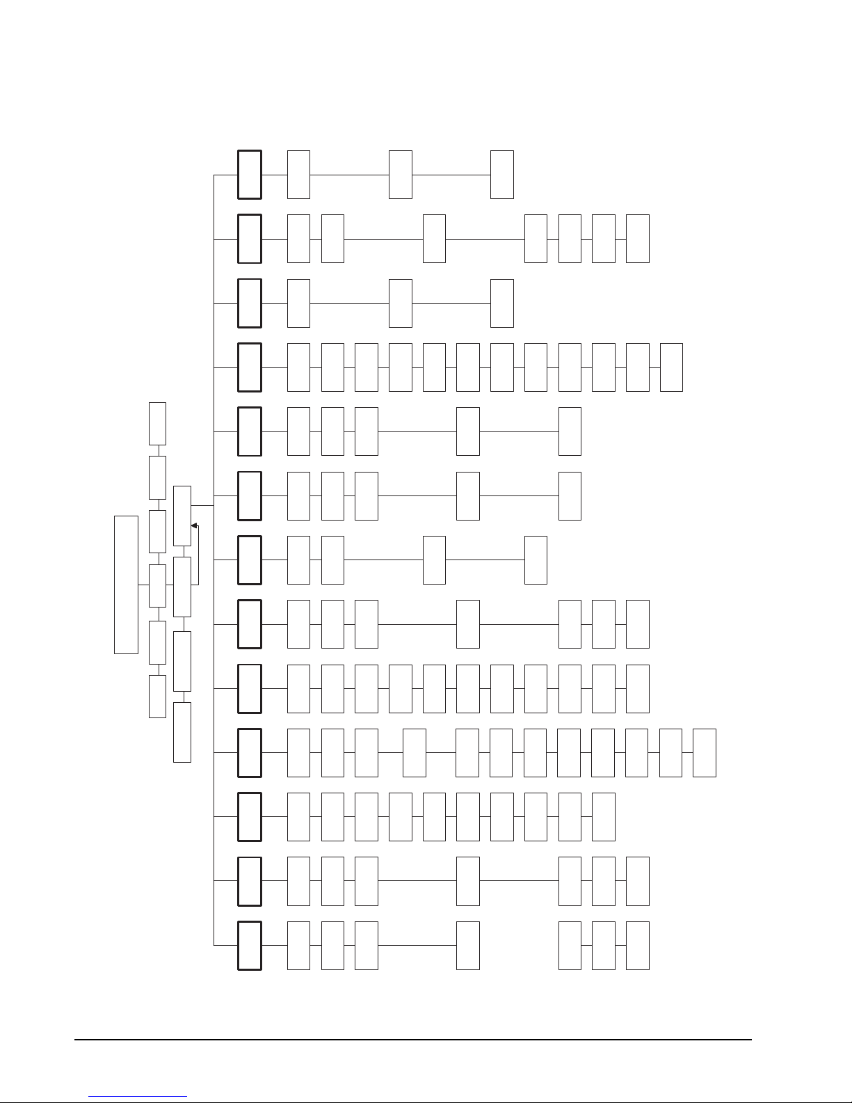
Regency® Model 4720 Control/Communicator Installation Manual (P/N 150476, Rev. A) Revised 10/98
18.2 Model 5520 Field Programmer
Figure 18.2a shows the Model 5520 menu structure. See the Model 5520 Programmer Manual (P/N
150479) for instructions on using the programmer.
ZONE
LOCATIONS
ZONE
TYPES
SYSTEM
MESSAGES
WINDOWS
DOOR
STATIONS
CODES
SECRET
OPTS.
ACCESS
#1
LOCATION
ZONE
TYPE #1
#0
MESSAGE
OPEN
NORM
DOORS
CODE #0
DURESS
TRIGGER
FOR #0
ACCESS
Z.T. #1
AUD FOR
NORM
CLOSE
DOORS
CODE #1
SECRET
CODE #0
FOR #1
ACCESS
SPEC
OPEN
DOORS
CODE #2
SECRET
CODE #1
. . .
. . .
. . .
SPEC
CLOSE
ACCESS
WINDOWS
. . .
#80
LOCATION
ZONE
TYPE #32
#63
MESSAGE
. . .
CODE #99
CODE #99
SPEC GRP
NORM GRP
. . .
. . .
ACCESS
FOR #99
Z.T. #32
AUD FOR
AREAS
TO CLOSE
DOORS
CODE #99
SECRET
CODE #99
ZONE
AREAS FOR
Z.T. #82
AUD FOR
TYPE #82
. . .
GRP #0
AREAS FOR
0476G37A.DSF
GRP #0
REV. 901009
5520 PROGRAMMER
EXIT
TIMERS
ETC. HEX 4720 5207 2820 ETC.
SAVE VERIFY LOAD EDIT
INTERCOM
DIALER
EXP.
INT.
SYSTEM
AUD
SHUTDOWN
ICOM
TIMEOUT
COMP
PHONE
LAST EXP. 1
ZONE MODE
DEF.
ZONE
(NOT USED)
MODE
ZONES
ZONES
OPTS.
LONG
RETRY
LAST EXP. 2
# OF
DNLD IF
DELAY
DIST. OK
IF FAIL
ZONE
AREAS
DEFAULT
ENTRY
DELAY
PHONE
TIMEOUT
LINES
2 PHONE
CODE
RESIDENCE
LAST
INTERNAL Z.
0 PUC
BELL TEST
LISTEN
ONE WAY
. . .
24 HR
ALARM
. . .
RING
. . .
. . .
DIAL TONE
#4
DELAY 1
ONLY
MEM DIAL
#4
FORMAT
24 HR
TROUBLE
ATTEMPTS
N.C.
NEED
TONE
TOUCH-
ACCOUNT
EXIT
ENTRY
DELAY
DAYS
CLOSED
SPECIAL
LISTEN
LISTEN
INTERIOR
INTERIOR
AUX CODE
MEMORY
STATIONS
TIME
LISTEN
BYPASS-
BYPASS-
AUTO
STATIONS
#4
CONTACTS
DAYS
PH #1
TO
TEST
AUTO
PH #2
MEMORY
LINE
ONLY
ONLY
USE LINE 1
ABLE
ABLE
CHIME
TEST
CLOSE
HOURLY
DIRECT
USE LINE 2
Figure 18.2a: Model 5520 Programmer Me nus
68
Page 79

Regency® Model 4720 Control/Communicator Installation Manual (P/N 150476, Rev. A) Revised 10/98
19 Touchpad Programming
All options can be addressed in Hex format. Hex programming is not recommended, except as a handy
troubleshooting tool. To obtain a Hex programming form, contact ITI Order Entry at 1-800-777-4841.
Note: Touchpad programming can only be accomplished through the use of a full-function touchpad with an LCD.
WARNING:
During programming, the system will not respond to alarms.
The following procedure shows how to set up the system for downloading using the 4-TEST method (see Section
18.1.2).
1. Apply power to the Model 4720. The system will power up in the Set Time mode.
2. Press MUTE, MUTE. You are now in the Normal Operating mode.
3. Press 6, TEST, followed by Code 0. Code 0 is factory set to “1-2-3-4-5-6”. This will place the Model 4720
into the Hex Programming mode. The display will indicate that you are at address $000.
4. Press CHM,6,0,TEST. This step takes you to address $060, the display will show $060:$XX.
At this point you will start entering the computer phone #. Each address location $060 through $067 can hold
two (2) digits of the phone number. You must fill all of the address locations. If your phone number does not
use all of the address locations, enter “FF” in the unused locations. To enter “FF” press BYPS, 6, BYPS, 6.
The example below shows how you would enter the phone number 555-1212.
Example:
Display = $060:$–– ––, press 5, 5, TEST.
Display = $061:$–– ––, press 5, 1, TEST.
Display = $062:$–– ––, press 2, 1, TEST.
Display = $063:$–– ––, press 2, BYPS, 6, TEST.
Display = $064:$–– ––, press BYPS, 6, BYPS, 6, TEST.
Display = $065:$–– ––, press BYPS, 6, BYPS, 6, TEST.
Display = $066:$–– ––, press BYPS, 6, BYPS, 6, TEST.
Display = $067:$–– ––, press BYPS, 6, BYPS, 6, TEST.
5. At this point the display will show $068:$XX. Press STAT, CLR, 7. The display will show
$068:$–––––––7. Press TEST. This step selects the Up/Down Report Enable.
6. Press CHM, 6, BYPS, 6, TEST, STAT, CLR. The display will show $06F:$––––––––. Press 4 if you ar e
using Touch-Tone dialing on Line 1 (5 for Touch-Tone on Line 2), then press TEST. If you are NOT using
Touch-Tone dialing, just press TEST.
7. Press CHM, BYPS, 1, 8, TEST. The display will show $0A8:$XX. For locations $0A8 through $0AA, you
must enter the account # that has been programmed into the downloading computer. Each address location can
hold two (2) digits of the account number. If the account number is not six (6) digits long, you must enter
leading zeros. The example below shows how to enter an account # of 1234.
Example:
Display = $0A8:$–– ––, press 0, 0, TEST.
Display = $0A9:$–– ––, press 1, 2, TEST.
Display = $0AA:$–– ––, press 3, 4, TEST.
8. After entering the account #, press MUTE, MUTE to exit Hex Programming mode.
9. Press 4 TEST, followed by Code 0 to begin the downloading process. The display will indicate that the Model
4720 is downloading. After about four (4) minutes the display will show READY. The 4720 has now been
programmed by the downloading computer.
69
Page 80

Regency® Model 4720 Control/Communicator Installation Manual (P/N 150476, Rev. A) Revised 10/98
20 Area Control Operation
Refer to the Model 4721 Area Control Software Instruction Manual (P/N 150483).
21 Model 4720 reporting Formats
• SIA (SEIA)
The SIA (Security Industry Association) format must be used with a Model 9000 Receiver. Each message will
be displayed in English followed by the zone number.
• FSK 2
The FSK 2 format is similar to the SIA format. This format must also be used with the Model 9000 Receiver.
Like the SIA format, all messages will be displayed in English at the 9000. Although FSK 2 reports the same
information as the SIA format, it cannot be used to trap on the account number for downloading.
• FSK 1, SK 4/2
If you will be reporting to a Model 8520 Receiver, you must use one of these two (2) formats. Since the 8520
has only two (2) digits for alarm codes, event types and zone numbers are combined into one message. The first
digit of the code is the type of report; the second digit is the last number of the zone.
Example: Any two (2) digit code beginn ing with the dig it “1” is a Bur glary Alarm. The s econd digit is th e last number
of the zone.
Code 11 = Burglary Alarm in zone 1, 11, 21, 31, 41, 51, 61, 71, or 81.
Code 15 = Burglary Alarm in zone 5, 15, 25, 35, 45, 55, 65, or 75.
Note: If you are using the Model 4726 dialer chip or Revision M of th e Model 47 20 board and h ave sele cted th e 16-zone
reporting option, this information does not apply to you. You will report Zones 1-16.
• Radionics BFSK
The Model 4720 can transmit using the Radionics BFSK format with 1400- or 2300-Hz Acknowledge. The
messages that will be printed are listed with the codes for FSK 1 and SK 4/2.
Note: There are no Door Access Reporting Codes when using the BFSK format. If this option is selected during
programming the Model 4720 will send a restoral for Zone 9.
The list on the next page shows all of the possible codes. When the letter “Z” appears in the code, it refers to the
last number of the zone. “Y” refers to the last digit of the user ID number.
The Radionics BFSK format can only report eight (8) zone codes. Zones 9 through 16 will report as zones 1
through 8; zones 17 through 24 will report as zones 1 through 8, etc. Because of this limitation, programming the
Model 4720 to report in both the Radionics BFSK and either the FSK or SK 4/2 formats is not advised.
Note: It is recommended that you use no more than eight (8) zones if your system is programmed to report in Radionics
BFSK format. However, if you choose to use more than eight (8) zones with the Radionics BFSK format, it is a
good idea to make every 8th zone (e.g., zones 1, 9, 17, etc.; zones 2, 10, 18, etc.; and so on) the same zone type
(e.g., Fire).
If you assign the zones in this manner, the letter “X” in the chart on the next page will be a digit that represents
every 8th zone number, as shown below:
Zone #
Digit reported
12345678910111213141516171819
1 2 3 4 5 6 7 8 1 2 3 4 5 6 7 8 1 2 3
…
…
(“X”)
70
Page 81

Regency® Model 4720 Control/Communicator Installation Manual (P/N 150476, Rev. A) Revised 10/98
FSK & SK 4/2
Code
Description Radionics
Intrusion Zone codes:
1Z
2Z
Burglary alarm
Alarm restore or bypass
(shunt) restore (burglary)
5Z
Burglary bypass (shunt)
Fire, Panic, Tamper, Gas, Sprinkler , Water,
Heat, Cold, and Holdup codes:
0Z
20
50
6Z
7Z
Alarm
Bypass (shunt) restore
Bypass (shunt)
Supervisory or trouble
Alarm restore, Supervisory restore,
and Trouble restore
Other codes:
09
30
31
32
33
34
35
36
37
39
4Y
60
69
70
79
80
8Y
9Y
Duress/Holdup
Dialer Test
Phone Line 1 trouble
Phone Line 2 trouble
Expansion trouble
Door left open or Door forced open * N/A
Phone Line 1 restore
Phone Line 2 restore
Expansion restore
Lost data * N/A
Closing report
AC lost
Low battery
AC restore
Battery restore
Door station * N/A
Door access * N/A
Open or alarm reset
BFSK Code
0X
EX
FX
0X
E0
F0
FX
EX
09
E9
FB
FB
FC
EB
EB
EC
CY
F0
F9
E0
E9
BY
Radionics
BFSK English
Alarm zone X
Restore zone X
Trouble zone X
was force armed
Alarm zone X
Restore Zone 0
Trouble zone 0
was force armed
Trouble zone X
Restore zone X
Alarm zone 9
Restore zone 9
Trouble zone B
Trouble zone B
Trouble zone C
Restore zone B
Restore zone B
Restore zone C
Close zone Y
Trouble zone 0
Trouble zone 9
Restore zone 0
Restore zone 9
Open zone Y
71
Page 82

Regency® Model 4720 Control/Communicator Installation Manual (P/N 150476, Rev. A) Revised 10/98
22 SIA Reporting Format
9000 Printer Code Status of 4720
Low battery 0
Battery restore 0
AC trouble 0
AC restore 0
Phone line trouble 1
Phone trouble 2
Phone line restore 1
Phone line restore 2
YT0
YR0
AT0
AR0
LT1
LT2
LR1
LR2
System battery low
Battery voltage back to normal
AC house power off
AC house power back on
Phone Line 1 not working
Phone Line 2 not working
Phone Line 1 back to normal
Phone Line 2 back to normal
Expansion trouble 0 ET0 Dialer trouble
Expansion trouble 1 ET1 Printer trouble
Expansion trouble 2 ET2 Zone Expander 1 trouble
Expansion trouble 3 ET3 Zone Expander 2 trouble
Expansion trouble 4 ET4 Intercom trouble
Expansion trouble 5 ET5 Auxiliary control (obs . Model 4150) trouble
Expansion trouble 6 ET6 Not used
Expansion trouble 7 ET7 Memory trouble
Expansion trouble 8 ET8 Control trouble
Expansion trouble 9 - 16 ET9 -
Not used
ET16
Expansion trouble 17 - 31 ET17 -
Touchpad 1 -15 trouble
ET31
Expansion restore 0 ER0 Dialer back to normal
Expansion restore 1 ER1 Printer back to normal
Expansion restore 2 ER2 Zone Expander 1 back to normal
Expansion restore 3 ER3 Zone Expander 2 back to normal
Expansion restore 4 ER4 Intercom (Model 4140) back to normal
Expansion restore 5 ER5 Auxiliary control (obs. Model 4150) back to
normal
Expansion restore 6 ER6 Not used
Expansion restore 7 ER7 EE memory back to normal
Expansion restore 8 - 16 ER8 -
Not used
ER16
Expansion restore 17 - 31 ER17 -
Touchpad 1 - 15 back to normal
ER31
Auto close CA 0 Sys tem aut om atic ally arme d
Auto open CO0 System automatically disarmed
Close ID 0 - 99 CL0 - 99 System arm ed by ac ces s Code 0 - 99
Force close ID 0 - 99 CW0-99 Forced armed by access Code 0 - 99
Supervisory close 0 CI0 Failed to open (still armed)
Supervisory open 0 OI0 Failed to close (still disarmed)
Close area 1 - 8 CG 1 - 8 Area 1 - 8 arme d
Open area 1 - 8 OG 1 - 8 Area 1 - 8 disarmed
Open reset alarm ID 0-99 OR 0 - 99 Alarm reset by acc ess Code 0 - 99
Door ID 0 - 99 DG 0 - 99 Door access granted Code 0 - 99
Door station 1 - 15 DS 1 - 15 A cc ess grant ed at Doo r 1 - 15
Door left open station 1 - 15 DO 1 - 15 Door left open at Touchpad 1 -15
Door forced open station 1 - 15DF 1 - 15 Door forced open at Touchpad 1 - 15
Auto test 0 RP0 Automatic dialer test
Manual test 0-99 RX0 - 99 System tested by Code 0 - 99
Data lost 0 RT1 Previous event co uld not be rep ort ed and the
* Note: The 4720 sends “MA”; the Model 4724-2 and the Model 4734-2 send “QA”.
information was lost
72
Page 83

Regency® Model 4720 Control/Communicator Installation Manual (P/N 150476, Rev. A) Revised 10/98
9000 Printer Code Status of 4720
In the zone types shown below, “Burglary” is used as an example. The first letter that will
be transmitted for each zone type is shown below:
H = Holdup
F = Fire
P = Panic
B = Burglary
T = Tamper
S = Sprinkler (formerly Gas)
W = Water
K = Heat
Z = Cold
U = Undefined
*M or Q = Emergency
(Burglary) Alarm 1 - 80 (B)A# Zone in alarm
(Burglary) Trouble 1 - 80 (B)T# Loop faulted or RF tr ansm itt er failed
(Burglary) Bypass 1 - 80 (B)B# Zone bypassed
(Burglary) Unbypass 1 - 80 (B)U# Zone unbypassed
(Burglary) Supervisory 1 - 80 (B)S# RF transmitter low battery
(Burglary) Restore 1 - 80 (B)R# Rest ore to norm al, due to:
Alarm Reset/Shutdown
Loop fault repaired
Transmitter battery replaced
Holdup alarm 0 HA0 Duress
Fire alarm 81 FA81 Fire panic key
* (Emergency) Alarm 82 * MA82 or
Aux key
QA 82
(Panic) Alarm 83 PA83 Police panic key
Temperature 0 - 255F ch. 1 DA 0-255 Analog temperature sensor has reached its
preset limit. The number following “temperature” is the actual temperature at time of
reporting.
Air flow ch. 2 DB 0 - 255 Air is movin g past the air flow senso r.
Humidity 10 - 90 prct ch. #3 DI 10 - 90 Analog humidity sensor has reached its preset
limit. The number following “humidity” is the
actual humidity at the time of reporting.
Fluid level 0 - 180 in. ch. #4 DM 0 -
180
Analog fluid level sensor has reached its pre-
set limit. The number following “fluid level” is
the actual level (in inches of water) at the
time of reporting.
* Note: The 4720 sends “MA”; the Model 4724-2 and the Model 4734-2 send “QA”.
The Model 4720 is compatible with the following UL Listed receivers (the formats used for each receiver are
shown in parentheses):
Regency Model 9000 (SIA < FSK1, SK 4/2, Radionics BFSK)
Regency Model 8510/8520 (FSK, SK 4/2)
Radionics Model 6000/6500 (Radionics BFSK)
FBI Model CP220 (SK 4/2, Radionics BFSK)
Osbourne/Hoffman Quickalert (SK 4/2)
73
Page 84

Regency® Model 4720 Control/Communicator Installation Manual (P/N 150476, Rev. A) Revised 10/98
23 Trouble/Error Messages
The following paragraphs describe the possible trouble and error messages that can be displayed on touchpads
using an LCD.
23.1 Troubles
PAPER
Printer is out of paper.
DATA LOST
Dialer has failed all of its attempts to communicate with the central station and the Model 4720 has
deleted the message(s) it was trying to send.
FAILED
Dialer cannot communicate with the central station. Appears in conjunction with DATA LOST.
BATTERY
Low or No Battery Conditio n.
Note: After power is restored—following a power loss that was long enough to cause a low battery condition—
the system may end up disarmed, regardless of the selection for “default mode” (see Section 17.1). Upon
receiving a Low-Battery Report from the panel, you should re arm the system either manually or by using
the downloading software.
AC
Loss of AC power.
LINE 1
Phone Line 1 is bad.
LINE 2
Phone Line 2 is bad (if using two (2) lines).
DEVICE 0
Problem with the Model 4720 dialer.
DEVICE 1
Problem with the Model 5260 Printer Interface (or the Model 5255 On-Site Printer).
DEVICE 2
Problem with Zone Expander 1.
DEVICE 3
Problem with Zone Expander 2.
DEVICE 4
Problem with the Model 4140 Intercom/Telephone Controller.
DEVICE 5
Problem with the Model 4150 External Control Module.
DEVICE 7
Memory (EEPROM) problem.
TOUCHPAD (1 - 15)
Problem with a touchpad.
74
Page 85

Regency® Model 4720 Control/Communicator Installation Manual (P/N 150476, Rev. A) Revised 10/98
DOOR (1 - 15)
Indicates a door has been left open (or forced open) when using the door contact feature with
commercial touchpads (see Note 2 below).
1 - 80
Indicates which zone is in trouble.
When the RF system is used, the first line of the display wi ll show either LOW BATTERY or TROUBLE.
The second line of the display will show which zone has a low battery or which zone is in trouble.
Note 1: Trouble Audible may be silenced by pressing MUTE, MUTE. Troubles will also automatically silence
when the trouble condition is corrected—the only exception is Day-Trouble zones, which will latch into
trouble until manually silenced.
Note 2: The 4180 trouble output should not be used to indicate DOOR-FORCED, because local door trouble
indication is inhibited when other doors in the system are accessed. Door troubles will be reported and
printed, but local audible annunciation cannot be depended on.
23.2 Errors
TRY AGAIN
This message means either an invalid code was used or the Model 4720 did not understand the
command.
RESTRICTED CODE
The code entered is incorrect for either the touchpad or the function that was being accessed.
RESTRICTED ZONE
A particular zone cannot be bypassed (shunted).
RESTRICTED TIME
Code was not entered within the time window selected during programming.
RESTRICTED DOOR
The code entered cannot be used to open that particular door.
24 Troubleshooting
When troubleshooting this system, it is always best to begin by looking for the simplest possible causes for a
malfunction. Check that all wires a re proper ly conn ected to th eir termin als. C heck for ob vious wir ing defe cts such
as missing insulation, which may cause shorts.
Malfunctions in the system are often caused by problems in the accessories, detectors, and sensors that are attached
to the Model 4720. Make sure that all accessories and external devices are in good working order before you begin
to troubleshoot the Model 4720 Control/Communicator cabinet. Also make sure that the telephone line is in good
working order.
Among the common problems in a Control/Communicator are problems with the power supply. Check that all
fuses are in good working order. Make sure that the battery and its charger are properly attached and receiving
power from the AC line.
Wiring can be checked through simp le continuity t ests, using your anal og or dig ita l mul time ter. For 2-wire cables,
disconnect the cable at each end. Next, connect each of the probes of your meter to one of the two (2) wires, and
switch the meter to the ohmmeter functions. You should now see an almost infinite resistance between the two (2)
wires. A low resistance reading means that you have a short somewhere in the middle.
75
Page 86
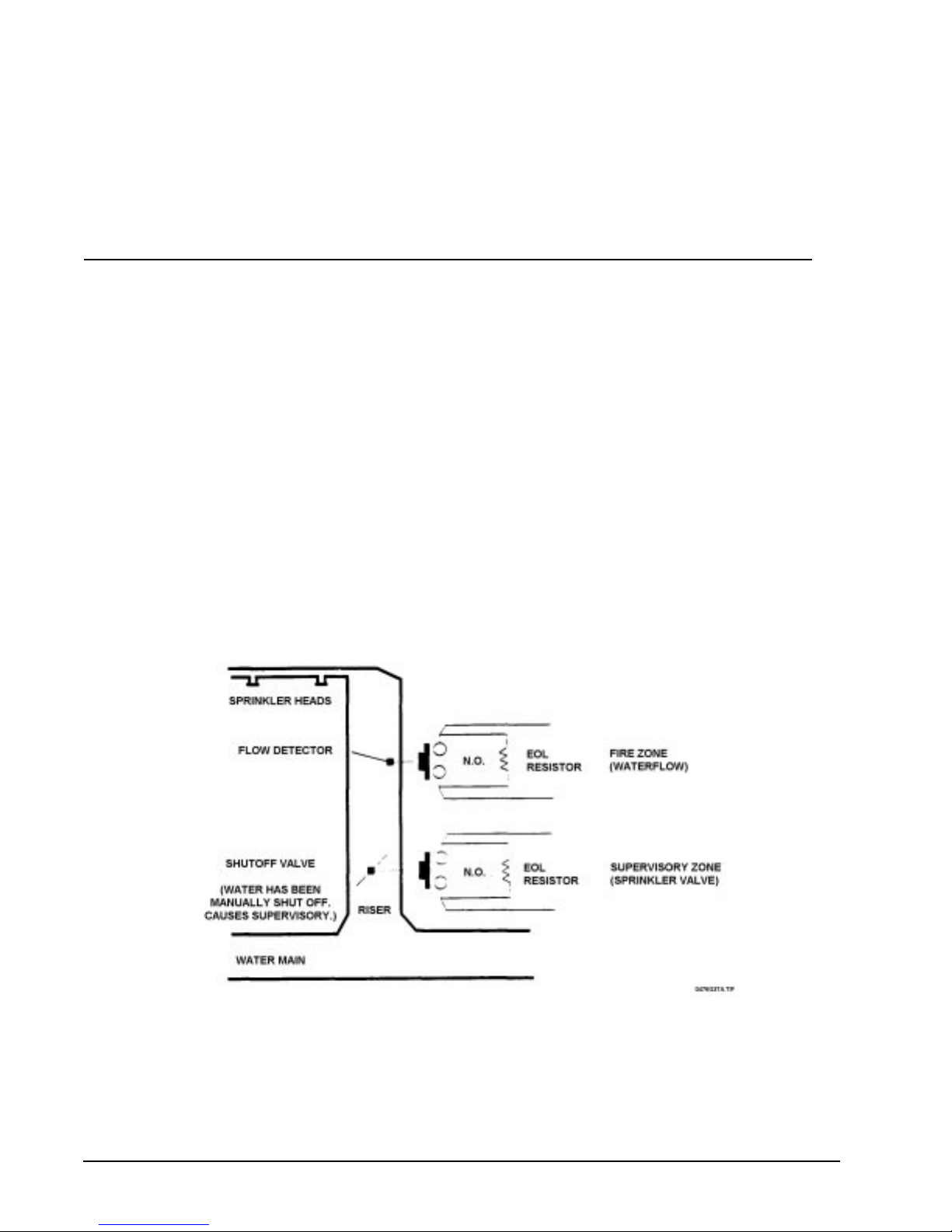
Regency® Model 4720 Control/Communicator Installation Manual (P/N 150476, Rev. A) Revised 10/98
Next, use a clip wire and short the t wo (2) wires to ge ther at the f ar e nd of th e cabl e, aw ay fro m the oh mmet er. You
should now see almost no resistance on your ohmmeter. If you continue to see a very high resistance, one or both
of the wires have been cut somewhere along the cable run.
Try to determine the location of any cuts or shorts in the cable. Shorts can be repaired with electrical tape, and cuts
can usually be spliced. If it is difficult to determine where a cable malfunction is located, it may be best to run a
new cable.
25 New features available with Revision N of the Model 4720
This section outlines the enhancements that are available with Revi sion N of the Model 4720.
25.1 Sprinkler Supervisory Zone Type
With Revision N of the Model 4720, the sprinkler supervisory zone type replaces the gas zone type. F i gure
25.1a and the chart below show how to wire and program sprinkler supervisory zones.
With Revision J of the Model 4724-2 control chip and Revision C of the Model 4734-2 control chip, the
sprinkler supervisory zone type is now available.
If the Model 5520 Desktop Programmer or the Model 5540 Downloading Software you are using still
shows GAS for the “SUPERVISORY” zone type, you can change these display messages. (Do not change
the display unless you are working with a 4720, Revision N or later board.)
1. Enter System Messages menu.
2. Locate message for “LOW BATTERY” and change to “SUPERVISORY”.
3. Locate message for “GAS” and change to “SUPERVISORY”.
Note: Both Steps 2 and 3 are necessary.
Figure 25.1a: Wiring Sprinkler Supervisory Zones
76
Page 87

Regency® Model 4720 Control/Communicator Installation Manual (P/N 150476, Rev. A) Revised 10/98
Program As System Response
Type = Fire
24 hr alarm
Water flow = Fire alarm
Wire break = Fire trouble
24 hr trouble
N.O.
No shutdown
Type = Sprinkler
24 hr alarm
24 hr trouble
Valve off = Sprinkler supervisory
Wire break = Sprinkler trouble
Press MUTE, MUTE + CODE to silence.
N.O.
25.2 LCD Operational Changes
With Revision N, if an alarm, trouble, or supervisory condition exists, the LCD scrolls the words ALARM,
TROUBLE, or SUPERVISORY. You can then press STAT to display the zone number and location of
trouble and supervisory conditions. Press MEM to display the zone number and location of alarms.
25.3 Memory Reporting During Auto Test
When an Auto Test occurs, the Model 4720 also sends a report of all unrestored events. It is not possible to
distinguish between old and new events during an Auto T est. Treat all alarms, troubles, and supervisories as
if they were new events. Note that memory reporting is not yet available with the Models 4724 and 4734.
77
Page 88

Regency® Model 4720 Control/Communicator Installation Manual (P/N 150476, Rev. A) Revised 10/98
26 REGENCY
Interactive Technologies, Inc. (ITI) warrants that Regency products manufactured by ITI
(Regency Product) will be free from defects in material and workmanship fo r one (1) year from
the date of purchase by the original purchaser.
This Limited Warranty extends only to the original purchaser and does not extend to consumers, end users or other secondary purchasers of Regency Product. Consumers or end users
should contact their selling dealer as to the nature and extent of the dealer's warran ty, if any.
ITI's obligation under this Limited Warranty is limited to the repair or replacement, at ITI’s
option, of any defective Regency Product at no additional charge. ITI reserves the right to
replace Regency Product under this Limited Warranty with new or remanufactured product. ITI
will not be responsible for labor costs of removal or reinstallation of Regency
repaired or replaced Regency Product is the n warranted under the terms of this Limited Warranty for the balance of the term of this Limited Warranty or for ninety (90) days, whichever is
longer.
This Limited Warranty does not cover the ITI PC-based software products or bat teries of any
type used in connection with Regency Product (p lease refe r to the ba ttery m anufact urer’s warranty, if any).
ITI is not responsible for conditions or applications over which ITI has no control. Defects or
problems as a result of such conditions or applications are not the resp onsibility of ITI. Such
conditions or applications include normal wear and tear, catastrophe, fault or negligence of the
user or the original purchaser, improper installation, application, maintenance or use of
Regency Product, or other causes external to Regency Product.
®
ONE YEAR LIMITED WARRANTY
Product. The
If you have a warranty claim, please contact Customer Service at 1-800-777-4841 and request
authorization to return the Regency Produc t. Customer Service will issue you a Return Merchandise Authorization (RMA) number. Return the Regency Product, freight prepaid, to ITI
together with reference to the RMA number and a written explanation setting forth the potential
defect in reasonable detail.
THE ORIGINAL PURCHASER'S EXCLUSIVE REMEDY WITH RESPECT TO ANY AND ALL
LOSSES OR DAMAGES RESULTING FROM ANY CAUSE WHATSOEVER SHALL BE REPAIR OR
REPLACEMENT, AS SPECIFIED ABOVE. ITI SHALL IN NO EVENT BE LIABLE FOR AN Y CONSEQUENTIAL OR INCIDENTAL DAMAGES, HOWEVER OCCASIONED, WHETHER BY NEGLIGENCE OR OTHERWISE. SOME STATES DO NOT ALLOW THE EXCLUSION OR LIMITATION OF
INCIDENTAL OR CONSEQUENTIAL DAMAGES, SO THIS LIMITATION OR EX C LUSION MAY NOT
APPLY TO YOU.
THE FOREGOING LIMITED WARRANTY IS IN LIEU OF ALL OTHER WARRANTIES, EXPRESS
OR IMPLIED, AND NO PERSON (INCLUDING ANY AGENT, DEALER OR REPRESENTATIVE OF
ITI) IS AUTHORIZED TO MAKE ANY REPRESENTATION OR WARRANTY CONCERNING
REGENCY PRODUCT EXCEPT TO REFER ORIGINAL PURCHASERS TO THIS LIMITED WARRANTY. ANY IMPLIED WARRANTIES (INCLUDING, WITHOUT LIMITATION, ANY IMPLIED WARRANTIES OF MERCHANTABILITY OR FITNESS FOR A PARTICULAR PURPOSE) ARE LIMITED
TO THE DURATION OF THIS LIMITED WARRANTY. SOME STATES DO NOT ALLOW LIMITATIONS ON HOW LONG AN IMPLIED WARRANTY LASTS, SO THIS LIMITATION MAY NOT APPLY
TO YOU.
THIS LIMITED WARRANTY GIVES YOU SPECIFIC LEGAL RIGHTS. YOU MAY ALSO HAVE
OTHER RIGHTS WHICH VARY FROM STATE TO STATE.
Interactive Technologies, Inc. * 2266 Second Street North * North St. Paul, Minnesota 55109
Rev 10/97- 466-1537
78
Page 89

Regency® Model 4720 Control/Communicator Installation Manual (P/N 150476, Rev. A) Revised 10/98
Index
Symbols
# Rings option . . . . . . . . . . . . . . . . 65
$000 address . . . . . . . . . . . . . . . . . 69
* key . . . . . . . . . . . . . . . . . . . . . 60
Numerics
09 code . . . . . . . . . . . . . . . . . . . . 71
0X code . . . . . . . . . . . . . . . . . . . . 71
0Z code . . . . . . . . . . . . . . . . . . . . 71
1 - 80 message . . . . . . . . . . . . . . . . 75
16-Zone Reporting option . . . . . . . . . . . 70
1Z code . . . . . . . . . . . . . . . . . . . . 71
2 Phone Lines option . . . . . . . . . . . . . . 5
20 code . . . . . . . . . . . . . . . . . . . . 71
24 hr alarm option . . . . . . . . . . . . . . 77
24 hr trouble option . . . . . . . . . . . . . . 77
24-hour zones . . . . . . . . . . . . . . . 5, 40
2Z code . . . . . . . . . . . . . . . . . . . . 71
30 code . . . . . . . . . . . . . . . . . . . . 71
31 code . . . . . . . . . . . . . . . . . . . . 71
32 code . . . . . . . . . . . . . . . . . . . . 71
33 code . . . . . . . . . . . . . . . . . . . . 71
34 code . . . . . . . . . . . . . . . . . . . . 71
35 code . . . . . . . . . . . . . . . . . . . . 71
36 code . . . . . . . . . . . . . . . . . . . . 71
37 code . . . . . . . . . . . . . . . . . . . . 71
39 code . . . . . . . . . . . . . . . . . . . . 71
4110 Zone Expanders . . . . . . . . . . . . . . 1
4130 Zone Expanders . . . . . . . . . . . . . . 3
4140 Intercom/Telephone Controller . . . . . . 74
4150 Auxiliary Control Module . . . . . .62, 74
4150 relay access . . . . . . . . . . . . . . . 61
4660C touchpads . . . . . . . . . . . . . . . 62
4660R touchpads . . . . . . . . . . . . . . . 62
4720 dialer . . . . . . . . . . . . . . . . . . 74
4Y code . . . . . . . . . . . . . . . . . . . . 71
50 code . . . . . . . . . . . . . . . . . . . . 71
5255 On-site Printers . . . . . . . . . . .74, 62
5260 Printer Interface . . . . . . . . . . . . . 74
5330 Modem . . . . . . . . . . . . . . . . . 67
5520 Desktop Programmer. . . . . . . . . . . 76
5520 Field Programmer . . . . . . . . . . 66, 68
5540 Downloading Software . . . . . 62, 66, 67
5Z code . . . . . . . . . . . . . . . . . . . . 71
60 code . . . . . . . . . . . . . . . . . . . . 71
69 code . . . . . . . . . . . . . . . . . . . . 71
6Z code . . . . . . . . . . . . . . . . . . . . 71
70 code . . . . . . . . . . . . . . . . . . . . 71
79 code . . . . . . . . . . . . . . . . . . . . 71
7Z code . . . . . . . . . . . . . . . . . . . . 71
80 code . . . . . . . . . . . . . . . . . . . . 71
8510 Receiver. . . . . . . . . . . . . . . . . 73
8520 Receiver. . . . . . . . . . . . . . . 70, 73
8Y code . . . . . . . . . . . . . . . . . . . 71
9000 Receiver. . . . . . . . . . . . . . . 70, 73
9Y code . . . . . . . . . . . . . . . . . . . 71
A
AB-12 Bell . . . . . . . . . . . . . . . . . . 35
AC Loss Hours option . . . . . . . . . . . 5, 65
AC lost . . . . . . . . . . . . . . . . . . . . 71
AC message . . . . . . . . . . . . . . . . . 74
AC power
failure
. . . . . . . . . . . . . . . . . . 74
lights . . . . . . . . . . . . . . . . . . . 12
wiring for. . . . . . . . . . . . . . . . . 24
AC restore . . . . . . . . . . . . . . . . . . 71
AC restore 0 printout . . . . . . . . . . . . . 72
AC trouble 0 printout . . . . . . . . . . . . . 72
access cards. . . . . . . . . . . . . . . . . . 60
access codes . . . . . . . . . . 61, 62, 72, 75
access, door. . . . . . . . . . . . . . . . . . 60
Access granted at door 1 - 15 . . . . . . . . 72
access modules . . . . . . . . . . . . . . . . . 2
access options. . . . . . . . . . . . . . . . . 66
access, relays . . . . . . . . . . . . . . . . . 61
accessories
compatible models
troubleshooting . . . . . . . . . . . . . . 75
adaptors, desktop . . . . . . . . . . . . . . . . 2
address locations . . . . . . . . . . . . . . . 69
address, hexadecimal . . . . . . . . . . . . . 69
Ademco
713 speakers
AB-12 Bell . . . . . . . . . . . . . . .5, 35
air flow sensors . . . . . . . . . . . . . . . . 73
ALARM message . . . . . . . . . . . . . . . 77
alarm reporting . . . . . . . . . . . . . . . . 61
Alarm reset by access code 0 - 99 . . . . . . 72
Alarm restore . . . . . . . . . . . . . . . . . 71
Alarm zone 9 message . . . . . . . . . . . . 71
Alarm zone X message . . . . . . . . . . . . 71
alarms
audible
Auto Test and . . . . . . . . . . . . . . 77
burglary. . . . . . . . . . . . . . . . . . 71
current draw . . . . . . . . . . . . . . . 18
fire . . . . . . . . . . . . . . . . . . . . 77
memory. . . . . . . . . . . . . . . . . . 59
no response to . . . . . . . . 6, 61, 67, 69
. . . . . . . . . . . . . . . . . . 56
. . . . . . . . . . . . . 1
. . . . . . . . . . . . . . . 36
79
Page 90

Regency® Model 4720 Control/Communicator Installation Manual (P/N 150476, Rev. A) Revised 10/98
reporting codes for . . . . . . . . . . . . 71
resetting . . . . . . . . . . . . . . . . . . 60
silencing. . . . . . . . . . . . . . . .75, 77
touchpad alert tones . . . . . . . . . . . . 56
alert tones . . . . . . . . . . . . . . . . . . . 56
Alm Rep Delay option . . . . . . . . . . . . 66
analog temperature sensor . . . . . . . . . . . 73
Answer Ring Detect option . . . . . . . .65, 67
Answering Machine Bypass feature . . . .14, 39
AR0 code . . . . . . . . . . . . . . . . . . . 72
Area 1 - 8 armed . . . . . . . . . . . . . . . 72
Area 1 - 8 disarmed. . . . . . . . . . . . . . 72
area control . . . . . . . . . . . . . . . . . . 70
Armed LED . . . . . . . . . . . . . . . . . . 56
arming the system . . . . . . . . . . . . .60, 72
AT0 code . . . . . . . . . . . . . . . . . . . 72
Attempts #1-4 option . . . . . . . . . . . . . 65
Audible Shutdown option . . . . . . . . . 3, 66
audio modules . . . . . . . . . . . . . . . . . 50
Auto Close option . . . . . . . . . . . . . . . . 4
AUTO CLOSE printout . . . . . . . . . . . . 72
Auto Open option . . . . . . . . . . . . . . . . 4
AUTO OPEN printout . . . . . . . . . . . . . 72
Auto test 0 printout . . . . . . . . . . . . . . 72
Auto Test option
memory reporting during
programming . . . . . . . . . . . . . . . . 3
Automatic dialer test . . . . . . . . . . . . . 72
automatic reports . . . . . . . . . . . . . . . 62
AUX key . . . . . . . . . . . . . . 58, 66, 73
auxiliary control . . . . . . . . . . . . . . . . 72
Auxiliary Control Module . . . . . . . . 62, 74
Auxiliary control trouble. . . . . . . . . . . . 72
auxiliary devices . . . . . . . . . . . . . . . . 31
auxiliary power supply . . . . . . . . . 2, 5, 34
. . . . . . . . . 77
B
batteries
backup type
cables for . . . . . . . . . . . . . . . . . 10
charger for . . . . . . . . . . . . . . . . . 2
installing . . . . . . . . . . . . . . . . . . 6
number required . . . . . . . . . . . . . . . 5
overcurrent protection and. . . . . . . . . 11
rechargeable type . . . . . . . . . . . . 2, 5
battery low . . . . . . . . . . . . . . . . . . 72
BATTERY message . . . . . . . . . . . . . . 74
Battery restore. . . . . . . . . . . . . . . . . 71
Battery restore 0 printout . . . . . . . . . . . 72
Battery voltage back to normal . . . . . . . . 72
Bell In Box . . . . . . . . . . . . . . . . . . . 5
Bell Test at Arming option . . . . . . . . . . . 4
bells
alarm type
auxiliary power for . . . . . . . . . . . . 34
commercial type. . . . . . . . . . . . . . 36
. . . . . . . . . . . . . . . . 25
. . . . . . . . . . . . . . . . . . 5
sounds . . . . . . . . . . . . . . . . . . 57
Wheelock 46T.G10 Polarized . . . . . . . 33
wiring for. . . . . . . . . . . . .24, 33, 34
BFSK format . . . . . . . . . . . . . . . 70, 71
blocks, jumper type . . . . . . . . . . . . . . 14
boards
Revision L
Revisions A - K . . . . . . . . . . . . . . 9
breaks, wire. . . . . . . . . . . . . . . . . . 77
burglary
alarms
commercial values for . . . . . . . . . . . 3
DC power switch and . . . . . . . . . . 14
devices used . . . . . . . . . . . . . . . 40
household value for. . . . . . . . . . . . . 3
Burglary bypass. . . . . . . . . . . . . . . . 71
Burglary zone. . . . . . . . . . . . . . . . . 73
BY code . . . . . . . . . . . . . . . . . . . 71
Bypass (shunt) restore option . . . . . . . . . 71
Bypass option . . . . . . . . . . . . . . . . . 71
bypassing
burglary alarms
zones . . . . . . . . . . . . . . . . . 71, 75
BYPS key . . . . . . . . . . . . . . . . 58, 59
. . . . . . . . . . . . . . . . . 8
. . . . . . . . . . . . . . . . . . 71
. . . . . . . . . . . . . . 71
C
CA0 code. . . . . . . . . . . . . . . . . . . 72
cables
battery
. . . . . . . . . . . . . . . . . . 10
shielded type . . . . . . . . . . . . . . . 24
touchpad connectors . . . . . . . . . . . 12
calculating
ID numbers
input numbers . . . . . . . . . . . . . . 46
zone numbers. . . . . . . . . . . . . 43, 46
California Fire Marshall. . . . . . . . . . . . 14
card readers . . . . . . . . . . . . . . . . . . . 2
cards, access . . . . . . . . . . . . . . . . . 60
see also ACCESS CARDS
CAUTION
central station signaling systems . . . . . . . . 5
CFM listed systems . . . . . . . . . . . . . . 35
CG 1 - 8 codes. . . . . . . . . . . . . . . . 72
charger, battery . . . . . . . . . . . . . . . . . 2
Chime function . . . . . . . . . . . . . . . . 60
Chime LED. . . . . . . . . . . . . . . . . . 56
chime tone . . . . . . . . . . . . . . . . 52, 56
CHM key . . . . . . . . . . . . . . . . . . . 58
CI0 code . . . . . . . . . . . . . . . . . . . 72
circuit boards
Revision L
Revisions A - K . . . . . . . . . . . . . . 9
circuits, PolySwitch Protectors . . . . . . . . 10
CL0 - 99 codes. . . . . . . . . . . . . . . . 72
clearing, memory . . . . . . . . . . . . . . . 60
see also MEMORY
. . . . . . . . . . . . . . . . 43
. . . . . . . . . . . . . . . . . . 66
. . . . . . . . . . . . . . . . . 8
80
Page 91

Regency® Model 4720 Control/Communicator Installation Manual (P/N 150476, Rev. A) Revised 10/98
clock speed adjustment . . . . . . . . . . . . 12
Close area 1 - 8 printout . . . . . . . . . . . 72
Close ID 0 - 99 printout . . . . . . . . . . . 72
Close zone Y message . . . . . . . . . . . . 71
Closing report . . . . . . . . . . . . . . . . . 71
CO0 code . . . . . . . . . . . . . . . . . . . 72
Code 0 . . . . . . . . . . . . . . . . 5, 66, 69
Code 1 . . . . . . . . . . . . . . . . . . . . . 5
Code 11. . . . . . . . . . . . . . . . . . . . 70
Code 15. . . . . . . . . . . . . . . . . . . . 70
CODE 2 feature. . . . . . . . . . . . . . . . 61
CODE 2 key . . . . . . . . . . . . . . . 58, 60
codes
factory default
program access . . . . . . . . . . . . . . 61
see also ACCESS CODES
setting for ID
stored in memory . . . . . . . . . . . . . 62
cold zones. . . . . . . . . . . . . . . . . 71, 73
commercial
bell wiring
burglary value . . . . . . . . . . . . . . . 3
fire protection. . . . . . . . . . . . . . . 47
fire value . . . . . . . . . . . . . . . . . . 3
panic keys and . . . . . . . . . . . . .5, 60
touchpads . . . . . . . . . . . 2, 55, 57, 60
connecting points, damaging. . . . . . . . . . 13
connecting the
4140 to the 4640
4140 to the 4720 . . . . . . . . . . . . . 49
4140 to the 7381 . . . . . . . . . . . . . 52
7381 to the 4140 . . . . . . . . . . . . . 52
9220 to the 4720 . . . . . . . . . . . . . 27
see also CONNECTIONS
connections
for telephone lines
for transformer . . . . . . . . . . . . . . 27
requirements for . . . . . . . . . . . . . . 2
see also CONNECTING THE
connectors, touchpads
contacts
combinations of
normally open and normally closed . . . . 32
control chips . . . . . . . . . . . . . . . . . 76
control panels
descriptions of
suggested mounting of . . . . . . . . . . 25
Control trouble . . . . . . . . . . . . . . . . 72
controls, environmental . . . . . . . . . . . . 53
Current Load Worksheet . . . . . . . . . . . 19
currents
calculating draw
total stand-by type . . . . . . . . . . . . . 5
CW0-99 code . . . . . . . . . . . . . . . . . 72
CY code . . . . . . . . . . . . . . . . . . . 71
. . . . . . . . . . . . . . . 4
. . . . . . . . . . . . . . . 30
. . . . . . . . . . . . . . . . 36
. . . . . . . . . . . . . 50
. . . . . . . . . . . . 38
. . . . . . . . . . . . . 12
. . . . . . . . . . . . . . 32
. . . . . . . . . . . . . . . 7
. . . . . . . . . . . . . 18
D
DA 0-255 code . . . . . . . . . . . . . . . . .73
Daily Test option. . . . . . . . . . . . . . . . 3
daisy-chaining
connectors
touchpads. . . . . . . . . . . . . . . . . .29
damaging connecting points. . . . . . . . . . .13
Data lost 0 printout. . . . . . . . . . . . . . .72
see also DATA LOST
DATA LOST message
data lost . . . . . . . . . . . . . . . . . 66, 72
dates, setting . . . . . . . . . . . . . . . . . .62
Day-Trouble zones . . . . . . . . . . . . . . .75
DB 0 - 255 code . . . . . . . . . . . . . . . .73
DC power switches . . . . . . . . . . . . 10, 14
Default Mode option . . . . . . . . . . . . . .65
defaults
clock speeds
EEPROM options . . . . . . . . . . . . .65
factory codes . . . . . . . . . . . . . . . . 4
see also FACTORY DEFAULTS
voltage levels
Delayed Bypass option . . . . . . . . . . . . .65
derived channels . . . . . . . . . . . . . . . . 2
descriptions
control panels
terminal strips . . . . . . . . . . . . . . .16
desktop
adapters
programmers . . . . . . . . . . . . . . . .76
detectors
ring type
smoke . . . . . . . . . . . . . .20, 27, 32
troubleshooting . . . . . . . . . . . . . . .75
DEVICE 0 message . . . . . . . . . . . . . .74
DEVICE 1 message . . . . . . . . . . . . . .74
DEVICE 2 message . . . . . . . . . . . . . .74
DEVICE 3 message . . . . . . . . . . . . . .74
DEVICE 4 message . . . . . . . . . . . . . .74
DEVICE 5 message . . . . . . . . . . . . . .74
DEVICE 7 message . . . . . . . . . . . . . .74
devices
auxiliary type
expansion type . . . . . . . . . . . . . . .48
DF 1 - 15 code . . . . . . . . . . . . . . . .72
DG 0 - 99 code . . . . . . . . . . . . . . . .72
DI 10 - 90 code . . . . . . . . . . . . . . . .73
Dialer back to normal . . . . . . . . . . . . .72
Dialer option . . . . . . . . . . . . . . . 62, 65
Dialer Test mode . . . . . . . . . . .72, 61, 71
Dialer trouble. . . . . . . . . . . . . . . . . .72
dialers
resetting
troubleshooting . . . . . . . . . . . . . . .74
dialing
phone numbers
TouchTone . . . . . . . . . . . . . . . . .69
. . . . . . . . . . . . . . . . .12
. . . . . . . . . . . . .74
. . . . . . . . . . . . . . . .12
. . . . . . . . . . . . . . . .12
. . . . . . . . . . . . . . . 7
. . . . . . . . . . . . . . . . . . 2
. . . . . . . . . . . . . . . 39, 67
. . . . . . . . . . . . . . . .31
. . . . . . . . . . . . . . . . . .61
. . . . . . . . . . . . . . .64
81
Page 92

Regency® Model 4720 Control/Communicator Installation Manual (P/N 150476, Rev. A) Revised 10/98
Digit reported zone . . . . . . . . . . . . . . 70
disabling
alarm reporting
CODE 2 . . . . . . . . . . . . . . . . . 61
disarming the system . . . . . . . . . . .60, 72
Disp Speed option . . . . . . . . . . . . . . . 65
displaying, alarm memory . . . . . . . . . . . 59
DLY key . . . . . . . . . . . . . . . . . . . 57
DM 0 - 180 code . . . . . . . . . . . . . . . 73
DO 1 - 15 code . . . . . . . . . . . . . . . . 72
Do Not Disturb option . . . . . . . . . . . . 64
DOOR (1 - 15) message . . . . . . . . . . . 75
door access . . . . . . . . . . . . . 71, 60, 67
Door access granted code 0 - 99 . . . . . . . 72
door access modules. . . . . . . . . . . . . . . 2
see also ACCESS, DOOR
Door Access Reporting Codes
Door Contact option. . . . . . . . . . . . . . 75
Door forced open . . . . . . . . . . . . . . . 72
Door forced open station 1 - 15 printout . . . 72
door holders, magnetic. . . . . . . . . . . . . 25
Door ID 0 - 99 printout. . . . . . . . . . . . 72
DOOR key . . . . . . . . . . . . . . . .57, 60
Door left (or forced) open. . . . . . . . . . . 71
Door left open. . . . . . . . . . . . . . . . . 72
Door left open station 1 - 15 printout . . . . . 72
Door Open Max option . . . . . . . . . . . . 66
Door station . . . . . . . . . . . . . . . . . . 71
Door station 1 - 15 printout . . . . . . . . . . 72
Door Strike option. . . . . . . . . . . . . . . 66
door strikes . . . . . . . . . . . . . . . . . . 25
doorbells. . . . . . . . . . . . . . . . . . . . 52
DOOR-FORCED message . . . . . . . . . . . 75
doors, left open or forced open . . . . . . . . 75
doorstrikes . . . . . . . . . . . . . . . . . . . 60
Download mode . . . . . . . . . . . . . . . . 61
downloading
request to download . . . . . . . . . . . . . . .62
troubleshooting
warning regarding . . . . . . . . . . .60, 67
downloading software . . . . . . . . . 2, 66, 67
DS 1 - 15 code . . . . . . . . . . . . . . . . 72
dual line monitor module . . . . . . . . . . . . 5
Duress event. . . . . . . . . . . . . . . . . . 73
duress signals . . . . . . . . . . . . . . . . . 60
Duress Trigger option . . . . . . . . . . . . . 66
Duress/Holdup option . . . . . . . . . . . . . 71
. . . . . . . . . . . . . . 61
. . . . . . . . . 70
. . . . . . . . . . . . . . 67
E
E/E Beep PZT option . . . . . . . . . . . . . 65
E0 code . . . . . . . . . . . . . . . . . . . . 71
E9 code . . . . . . . . . . . . . . . . . . . . 71
earth grounding wire . . . . . . . . . . . . . 11
see also GROUND WIRE
EB code
EC code . . . . . . . . . . . . . . . . . . . . 71
. . . . . . . . . . . . . . . . . . . . 71
EEPROMs
factory programmed options
losing data . . . . . . . . . . . . . . . . 66
memory back to normal . . . . . . . . . 72
memory problems. . . . . . . . . . . . . 74
programmer . . . . . . . . . . . . . . . . . 2
reprogramming . . . . . . . . . . . . . . 66
risk of scrambling . . . . . . . . . . . . 60
electric doorstrikes . . . . . . . . . . . . . . 25
see also DOORSTRIKES
electrical tap
Electrically Erasable Programmable Read Only Memory
see EEPROMs
emergency alarm bell
Emergency zone . . . . . . . . . . . . . . . 73
enabling CODE 2 . . . . . . . . . . . . . . . 61
enclosures, transformers . . . . . . . . . . . . . 5
end-of-line (EOL) resistor . . . . . . . . . . . 32
Entry Delay 1 option . . . . . . . . . . . . . 66
Entry Delay 2 option . . . . . . . . . . . . . 66
entry warning tones . . . . . . . . . . . . . . 56
environment controls . . . . . . . . . . . . . 53
ER0 code . . . . . . . . . . . . . . . . . . . 72
ER1 code . . . . . . . . . . . . . . . . . . . 72
ER17 - ER31 codes. . . . . . . . . . . . . . 72
ER2 code . . . . . . . . . . . . . . . . . . . 72
ER3 code . . . . . . . . . . . . . . . . . . . 72
ER4 code . . . . . . . . . . . . . . . . . . . 72
ER5 code . . . . . . . . . . . . . . . . . . . 72
ER6 code . . . . . . . . . . . . . . . . . . . 72
ER7 code . . . . . . . . . . . . . . . . . . . 72
ER8 - ER16 codes . . . . . . . . . . . . . . 72
error messages . . . . . . . . . . . . . . 74, 75
ESL 204A Power Supervision Unit . . . . . . 32
ESL 445AT Smoke Detectors . . . . . . . . . 33
ET0 code . . . . . . . . . . . . . . . . . . . 72
ET1 code . . . . . . . . . . . . . . . . . . . 72
ET2 code . . . . . . . . . . . . . . . . . . . 72
ET3 code . . . . . . . . . . . . . . . . . . . 72
ET4 code . . . . . . . . . . . . . . . . . . . 72
ET5 code . . . . . . . . . . . . . . . . . . . 72
ET6 code . . . . . . . . . . . . . . . . . . . 72
ET7 code . . . . . . . . . . . . . . . . . . . 72
ET8 code . . . . . . . . . . . . . . . . . . . 72
ET9 - ET16 codes . . . . . . . . . . . . . . 72
ET17 - ET31 codes. . . . . . . . . . . . . . 72
events, unresolved. . . . . . . . . . . . . . . 77
EX code . . . . . . . . . . . . . . . . . . . 71
Exception OP/CL option . . . . . . . . . . . . 5
Exit Delay option . . . . . . . . . . . . . . . 66
exit warning tones . . . . . . . . . . . . . . 56
exiting, Program mode . . . . . . . . . . . . 62
expansion
buses
connectors . . . . . . . . . . . . . . . . 12
devices . . . . . . . . . . . . . . . . 13, 48
zones . . . . . . . . . . . . . . . . . 31, 40
. . . . . . . . . . . . . . . . . 76
. . . . . . . . . . . . . 57
. . . . . . . . . . . . . . . . . . . 53
. . . . . . . 65
82
Page 93

Regency® Model 4720 Control/Communicator Installation Manual (P/N 150476, Rev. A) Revised 10/98
Expansion restore . . . . . . . . . . . . . . . 71
Expansion restore X printout . . . . . . . . . 72
Expansion trouble . . . . . . . . . . . . . . . 71
Expansion trouble X printout . . . . . . . . . 72
expansion zones options. . . . . . . . . . . . 65
external devices . . . . . . . . . . . . . . . . 75
external, speakers . . . . . . . . . . . . . . . 36
F
F0 code . . . . . . . . . . . . . . . . . . . . 71
F9 code . . . . . . . . . . . . . . . . . . . . 71
FA81 code . . . . . . . . . . . . . . . . . . 73
factory defaults
clock speeds
codes . . . . . . . . . . . . . . . . . . . . 4
see also FACTORY DEFAULT
voltage levels
factory-programmed EEPROMs . . . . . . . . 65
Fail Attempt option . . . . . . . . . . . . . . 65
failed indicator . . . . . . . . . . . . . . . . 39
FAILED message . . . . . . . . . . . . . . . 74
Failed to close . . . . . . . . . . . . . . . . 72
Failed to open. . . . . . . . . . . . . . . . . 72
failure, power . . . . . . . . . . . . . . . . . 74
see also AC POWER
Fast Blow Fuses
FB code. . . . . . . . . . . . . . . . . . . . 71
FBI Model CP220 Receiver . . . . . . . . . . 73
FC code. . . . . . . . . . . . . . . . . . . . 71
FCC requirements . . . . . . . . . . . . . . . . 3
features . . . . . . . . . . . . . . . . . . .1, 76
ferrite shield beads . . . . . . . . . . . . . . 24
ferrite toroid. . . . . . . . . . . . . . . . . . 24
field programmer . . . . . . . . . . . . . . . 68
field wires. . . . . . . . . . . . . . . . . . . 13
fire
commercial
household . . . . . . . . . . . . . . . . . . 3
NFPA protection from . . . . . . . . . . 47
testing UL 985 systems . . . . . . . . . . . 7
UL installation requirements . . . . . . . . 5
warning systems . . . . . . . . . . . . . . 4
Fire (Zone #1) option . . . . . . . . . . . . . 65
fire alarms
bell tones for
bell wiring for . . . . . . . . . . . . . . 33
trouble and error messages . . . . . . . . 77
Walk Test mode and . . . . . . . . . . . . 6
warning about. . . . . . . . . . . . . . . 61
Fire codes . . . . . . . . . . . . . . . . . . . 71
FIRE key . . . . . . . . . . . . . . . . . 58, 66
Fire option . . . . . . . . . . . . . . . . . . 66
Fire panic key event . . . . . . . . . . . . . 73
Fire troubles. . . . . . . . . . . . . . . . . . 77
Fire zone . . . . . . . . . . . . . . . . . . . 73
Force Arm option . . . . . . . . . . . . . . . . 4
. . . . . . . . . . . . . . . 12
. . . . . . . . . . . . . . . 12
. . . . . . . . . . . . . . . 11
. . . . . . . . . . . . . . . . . 3
. . . . . . . . . . . . . . . 57
FORCE CLOSE . . . . . . . . . . . . . . . .65
Force close ID 0 - 99 printout . . . . . . . . .72
Format #1-4 option . . . . . . . . . . . . . . .65
formulas . . . . . . . . . . . . . . . . . . . .43
Friday testing . . . . . . . . . . . . . . . . . .63
FSK 1 format. . . . . . . . . . . . . . . . . .70
FSK 2 format. . . . . . . . . . . . . . . . . .70
FSK codes . . . . . . . . . . . . . . . . . . .71
FSK format . . . . . . . . . . . . . . . . . . .73
FSK1 format . . . . . . . . . . . . . . . . . .73
function keys . . . . . . . . . . . . . . . . . .57
functions, touchpads . . . . . . . . . . . . . .59
fuses
troubleshooting
Fast-Blow type . . . . . . . . . . . . . . .11
FX code . . . . . . . . . . . . . . . . . . . .71
. . . . . . . . . . . . . . .75
G
gang box . . . . . . . . . . . . . . . . . . . .25
Gas codes . . . . . . . . . . . . . . . . . . .71
GAS message. . . . . . . . . . . . . . . . . .76
Gas zone type . . . . . . . . . . . . . . 73, 76
Grade A Local (UL 609) . . . . . . . . . . . .35
Grade A Mercantile (UL 365) . . . . . . . 5, 35
Grade B Central Station (UL 1610) . . . . . .35
Ground Start option. . . . . . . . . . . . . . . 5
ground start relays . . . . . . . . . . . . . . .38
ground start telephone networks . . . . . . . .38
grounding wires. . . . . . . . . . . . . . . . .11
see also EARTH GROUND
H
HA0 code . . . . . . . . . . . . . . . . . . .73
hardware . . . . . . . . . . . . . . . . . . . . 3
hardwired
expanders
loops . . . . . . . . . . . . . . . . . . . . 4
Heat codes . . . . . . . . . . . . . . . . . . .71
Heat zone. . . . . . . . . . . . . . . . . . . .73
Hex Programming mode . . . . 61, 62, 66, 69
hexadecimal (hex) addresses . . . . . . . . . .69
high frequency noise . . . . . . . . . . . . . .24
Holdup codes . . . . . . . . . . . . . . . . . .71
Holdup zone . . . . . . . . . . . . . . . . . .73
Holdup/Duress option . . . . . . . . . . . . . .71
holes, knockout type . . . . . . . . . . . . . . 6
household
burglary value
fire value. . . . . . . . . . . . . . . . . . 3
fire warning systems (UL 985) . . . . . . . 4
housing
see also ENCLOSURES
transformer
humidity sensor. . . . . . . . . . . . . . . . .73
. . . . . . . . . . . . . . . . . .13
. . . . . . . . . . . . . . . 3
. . . . . . . . . . . . . . . . . 2
83
Page 94

Regency® Model 4720 Control/Communicator Installation Manual (P/N 150476, Rev. A) Revised 10/98
I
ICOM key. . . . . . . . . . . . . . . . . 58, 63
ICOM timeout . . . . . . . . . . . . . . . . . . 4
ID codes . . . . . . . . . . . . . . . . . . . 30
ID (identification) numbers
sensor loops
SmartSensors . . . . . . . . . . . . . . . 42
touchpads . . . . . . . . . . . . . . . . . . . . .70
indicators
induced noise . . . . . . . . . . . . . . . . . 24
information, lost . . . . . . . . . . . . . .66, 72
input zones . . . . . . . . . . . . . . . . . . . 5
installing
INT key . . . . . . . . . . . . . . . . . . . . 57
Intercom Module . . . . . . . . . . . . . 12, 48
Intercom option . . . . . . . . . . . . . .63, 72
Intercom Paging option . . . . . . . . . . . . 63
Intercom Time-out option . . . . . . . . . . . 63
Intercom trouble . . . . . . . . . . . . . . . . 72
Intercom/Telephone Controller . . . . . . . . . 74
intercoms
interfaces, printer . . . . . . . . . . . 2, 53, 74
Interior function . . . . . . . . . . . . . . . . 60
Interior LED. . . . . . . . . . . . . . . . . . 56
internal zones . . . . . . . . . . . . . . .31, 32
Internal Zones option . . . . . . . . . . . . . 65
Intrusion (Zones 17-80) option . . . . . . . . 65
Intrusion Alarm Bell. . . . . . . . . . . . . . 57
intrusion input zone . . . . . . . . . . . . . . . 5
Intrusion Zone codes . . . . . . . . . . . . . 71
Intrusion Zone option . . . . . . . . . . . . . 66
. . . . . . . . . . . . . . . . . . . 39
4720 Control Panel
batteries . . . . . . . . . . . . . . . . . . . 6
Model 4130 Zone Expanders . . . . . . . 46
the panel . . . . . . . . . . . . . . . . . 18
transformers . . . . . . . . . . . . . . . . 25
connecting points for
expansion connectors for . . . . . . . . . 13
. . . . . . . . . . . . . . . . 40
. . . . . . . . . . . . 24
. . . . . . . . . . . 14
J
jumpers
caution regarding use
explained . . . . . . . . . . . . . . . . . 14
. . . . . . . . . . . 11
K
keys, function type . . . . . . . . . . . . . . 57
keyswitches, mechanical . . . . . . . . . . . . 31
knockout holes . . . . . . . . . . . . . . . . . 6
L
Last Exp1 Z# option . . . . . . . . . . . . . 65
Last Exp2 Z# option . . . . . . . . . . . . . 65
Last Internal Z# option . . . . . . . . . . . . 65
LCDs
bypassing zones and
changes to. . . . . . . . . . . . . . . . . 77
. . . . . . . . . . . . 59
PAPER message . . . . . . . . . . . . . 53
touchpads with . . . . . . . . . . . . . . 66
LEDs
bypassing zones and
excessive current draw . . . . . . . . . . 18
indications . . . . . . . . . . . . . . . . 56
red type . . . . . . . . . . . . . . . . . 11
Watchdog Modules and. . . . . . . . . . 48
limited warranty. . . . . . . . . . . . . . . . 78
LINE 1 message . . . . . . . . . . . . . . . 74
LINE 2 message . . . . . . . . . . . . . . . 74
Line Monitor option . . . . . . . . . . . . . . 5
line monitoring . . . . . . . . . . . . . . . . 13
line seizure . . . . . . . . . . . . . . . . . . . 1
Listen Only option . . . . . . . . . . . . . . 63
Listen Time option . . . . . . . . . . . . . . . 4
listen-in modules
connecting
explained . . . . . . . . . . . . . . 2, 3, 12
microphones and . . . . . . . . . . . . . 53
Listen-Only Paging option . . . . . . . . . . 63
locations, address . . . . . . . . . . . . . . . 69
Local Protective Signaling Systems (NFPA 72) 34
Local Protective Signaling Systems (UL 864) 4, 5
long range RF . . . . . . . . . . . . . . . . . 2
Loop faulted . . . . . . . . . . . . . . . . . 73
loop start telephone networks . . . . . . . . . 38
loops
panic hardwire type
serial . . . . . . . . . . . . . . . . . . . 40
wiring . . . . . . . . . . . . . . . . . . 24
lost data . . . . . . . . . . . . . . . . . 71, 72
Low battery. . . . . . . . . . . . . . . . . . 71
Low battery 0 printout . . . . . . . . . . . . 72
LOW BATTERY message . . . . . . . . 75, 76
low resistance . . . . . . . . . . . . . . . . . 75
LR1 code . . . . . . . . . . . . . . . . . . . 72
LR2 code . . . . . . . . . . . . . . . . . . . 72
LT1 code . . . . . . . . . . . . . . . . . . . 72
LT2 code . . . . . . . . . . . . . . . . . . . 72
. . . . . . . . . . . . . . . . 14
. . . . . . . . . . . 59
. . . . . . . . . . . . . 4
M
MA82 code . . . . . . . . . . . . . . . . . . 73
magnetic door holders. . . . . . . . . . . . . 25
magnetic reed switches . . . . . . . . . . . . 41
malfunctions, troubleshooting . . . . . . . . . 76
Manual test 0-99 printout . . . . . . . . . . . 72
Max SKEY ID option . . . . . . . . . . . . 65
mechanical keyswitch . . . . . . . . . . . . . 31
MEM key. . . . . . . . . . . . . . .58, 64, 77
memory
alarms in
codes in . . . . . . . . . . . . . . . . . 62
problems with . . . . . . . . . . . . . . 74
reporting . . . . . . . . . . . . . . . . . 77
telephone numbers in . . . . . . . . . . . 64
. . . . . . . . . . . . . . . . . 59
84
Page 95

Regency® Model 4720 Control/Communicator Installation Manual (P/N 150476, Rev. A) Revised 10/98
memory location #1 . . . . . . . . . . . . . . 64
memory location #2 . . . . . . . . . . . . . . 64
Memory trouble . . . . . . . . . . . . . . . . 72
menu structure . . . . . . . . . . . . . . . . 68
messages
. . . . . . . . . . . . . . . . . . . 74
error
trouble . . . . . . . . . . . . . . . . . . 74
system . . . . . . . . . . . . . . . . . . 66
microphones
diagram of
gain adjustment for . . . . . . . . . . 50, 51
turning on and off . . . . . . . . . . . . 64
with amplifiers . . . . . . . . . . . . . . 52
models
4110 Zone Expander
4115 Zone Expander . . . . . . . . . .1, 44
4125 Zone Expander . . . . . . . 1, 13, 44
4130 Zone Expander . . . . . . . 1, 13, 46
4135 Remote Receiver . . . . . . . . . 1, 3
4140 Intercom Module1, 12, 13, 14, 48, 52
4150 Environment Control . . . . . . . . 53
4150 Relay Module . . . . . . . . . . .2, 13
4160 Supervised Bell Module . . . . 2, 5, 34
4165 Transformer Housing . . . . . 2, 5, 25
4175 Dual Line Monitor Module2, 5, 13, 14, 22
4180 Status Display Module . . . . . .2, 13
4184 Watchdog Trouble Module2, 5, 22, 47
4195 Auxiliary Power Supply2, 5, 27, 28, 34
4203 SlimLine Touchpad . . . 2, 3, 22, 30
4205 SlimLine Touchpad . . . . . . . . . . 2
4300 Card Reader . . . . . . . . . . . . . 2
4360 Desktop Adapter . . . . . . . . . . . 2
4420 Door Access Module . . . . . . . . . 2
4433 (4430) Remote Touchpad . . . . . . . 5
4553 residential wall-mount touchpad . . . . 2
4640 Audio Modules . . . . . . . . . . . 50
4640 Intercom Station . . . . . . . . . . . 1
4660 touchpads . . . . . . . . . . . 2, 3, 55
4720 Control/Communicator. . . . . . . . 22
5255 On-Site Printer . . . . . 2, 5, 13, 53
5260 Printer Interface . . . . . . . 2, 13, 53
5520 EEPROM Programmer . . . . . .2, 13
5530 Modem . . . . . . . . . . . . . . . . 2
5540 Downloading Software . . . . . . . . 2
6712 Rechargeable Battery . . . . . . . 2, 5
7181 Fire Zone Converter . . . . . . 32, 33
7367 Two-way Audio Listen-in Module . 53
7369 Listen-in Module . . . . . . . 2, 3, 12
7381 Front Door Intercom Station . . . . 52
7630 EOL Resistor . . . . . . . . . . 32, 33
7890 Transient-Surge Protector . . . . . . 26
9220 Power Transformers . . . . . . . 25, 27
9220 UL listed Class II Power Transformer26
modems . . . . . . . . . . . . . . . . . . .2, 67
mode, testing . . . . . . . . . . . . . . . . . 61
. . . . . . . . . . . . . . 53, 54
. . . . . . . . . . . 40
modules
audio module type
door access type . . . . . . . . . . . . . . 2
dual line monitor type . . . . . . . . . . .13
intercom type. . . . . . . . . . . . . . . .12
listen-in type . . . . . . . . . . 2, 3, 12, 53
relay type . . . . . . . . . . . . . . . . .13
status display type . . . . . . . . . . . 2, 13
supervised bell type . . . . . . . . 2, 5, 34
supervised temporal-three siren . . . . . . . 4
watchdog trouble type . . . . . 2, 5, 22, 47
moisture, avoiding . . . . . . . . . . . . . . .24
Monday testing . . . . . . . . . . . . . . . . .63
mounting
control panel
touchpads. . . . . . . . . . . . . . . 28, 30
Must Report to ph#1 option . . . . . . . . . .65
MUTE key . . . . . . . . . . . . . . . . . . .58
Muxed Touchpads option . . . . . . . . . . . .31
. . . . . . . . . . . . .50
. . . . . . . . . . . . . 24, 25
N
N.O. option . . . . . . . . . . . . . . . . . . .77
networks, loop start. . . . . . . . . . . . . . .38
new features . . . . . . . . . . . . . . . . . .76
NFPA requirements . . . . . . . . . .14, 25, 47
NFPA 71 . . . . . . . . . . . . . . . . . . . . 5
NFPA 72 . . . . . . . . . . . . . . . . 4, 5, 34
NFPA 72A . . . . . . . . . . . . . . . . . . . 2
NFPA 72E . . . . . . . . . . . . . . . . . . .32
No Delay LED . . . . . . . . . . . . . . . . .56
no response to alarms . . . . . . . . . . . . .69
No Shutdown option . . . . . . . . . . . . . .77
No Shutdown zone . . . . . . . . . . . . . . .66
noise, avoiding induced . . . . . . . . . . . . .24
non-medical alarm bell . . . . . . . . . . . . .57
non-UL installations . . . . . . . . . . . . . .17
Norm Close option . . . . . . . . . . . . . . .66
Norm Open option . . . . . . . . . . . . . . .66
Normal Operation mode . . . . . . . . . . . .62
normally closed contacts . . . . . . . . . 32, 69
normally open contacts . . . . . . . . . . . . .32
numbering system, hexadecimal . . . . . . . . .62
O
OG 1 - 8 codes . . . . . . . . . . . . . . . .72
ohmmeters . . . . . . . . . . . . . . . . . . .75
OI0 code . . . . . . . . . . . . . . . . . . . .72
on-site printers . . . . . . . . . . . . 2, 53, 62
Open area 1 - 8 printout . . . . . . . . . . . .72
Open or alarm reset . . . . . . . . . . . . . .71
Open reset alarm ID 0-99 printout . . . . . . .72
Open zone Y message . . . . . . . . . . . . .71
options
access
. . . . . . . . . . . . . . . . . . .66
system . . . . . . . . . . . . . . . . . . .65
programming . . . . . . . . . . . . . . .1, 3
85
Page 96

Regency® Model 4720 Control/Communicator Installation Manual (P/N 150476, Rev. A) Revised 10/98
OR 0 - 99 codes . . . . . . . . . . . . . . . 72
Osbourne/Hoffman Quickalert Receiver . . . . 73
oscillations. . . . . . . . . . . . . . . . . . . 50
outlets . . . . . . . . . . . . . . . . . . . . . 25
outputs . . . . . . . . . . . . . . . . . . 60, 75
overcurrent protection . . . . . . . . . . . . . 10
P
paging . . . . . . . . . . . . . . . . . . . . . 63
Panic codes . . . . . . . . . . . . . . . . . . 71
panic hardwire loops . . . . . . . . . . . . . . 4
panic keys
. . . . . . . . . . . . . . . . . . . 60
alarms
commercial type. . . . . . . . . . . . . . . 5
explained . . . . . . . . . . . . . . . . . 58
Panic zone. . . . . . . . . . . . . . . . . . . 73
PAPER message . . . . . . . . . . . . . . 53, 74
perimeter zones . . . . . . . . . . . . . . . . . 5
Phone line 1. . . . . . . . . . . . . . . . . . 72
Phone line 1 restore . . . . . . . . . . . . . . 71
Phone line 1 trouble . . . . . . . . . . . . . . 71
Phone line 2. . . . . . . . . . . . . . . .72, 74
Phone line 2 restore . . . . . . . . . . . . . . 71
Phone line 2 trouble . . . . . . . . . . . . . . 71
Phone Line Monitor connector. . . . . . . . . 12
Phone line restore 1 printout . . . . . . . . . 72
Phone line restore 2 printout . . . . . . . . . 72
Phone line trouble 1 printout . . . . . . . . . 72
phone lines . . . . . . . . . . . . . . . . . . . 2
see also PHONES
phone numbers
dialing
. . . . . . . . . . . . . . . . . . . 64
last number called. . . . . . . . . . . . . 64
Phone trouble 2 printout . . . . . . . . . . . . 72
phones
connecting points
dual line monitor . . . . . . . . . . . . . . 5
line connections . . . . . . . . . . . . . . 38
line seizure . . . . . . . . . . . . . . . . . 1
options for . . . . . . . . . . . . . . . . 64
see also PHONE LINES
wiring
. . . . . . . . . . . . . . . . . . . 24
plug-on terminal strips . . . . . . . . . . . . . 15
POL key . . . . . . . . . . . . . . . . .58, 73
polarity . . . . . . . . . . . . . . . . . . . . 10
polarized bells . . . . . . . . . . . . . . . . . 33
POLICE key. . . . . . . . . . . . . . . . . . 66
PolySwitch circuit protectors. . . . . . . . . . 10
power
failures
lights for . . . . . . . . . . . . . . . . . 12
switches . . . . . . . . . . . . . . . .10, 14
wiring for supervised bells . . . . . . . . 34
see also AC POWER
power back on
power off . . . . . . . . . . . . . . . . . . . 72
. . . . . . . . . . . . . . . .10, 74
. . . . . . . . . . . . . . . . 72
. . . . . . . . . . . . . 14
power supply
4194 Auxiliary Power Supply
4195 Auxiliary Power Supply . . 5, 27, 34
troubleshooting . . . . . . . . . . . . . . 75
precautions, wiring . . . . . . . . . . . . . . 24
preconnection requirements . . . . . . . . . . . 2
preprogrammed messages . . . . . . . . . . . 66
Printer back to normal . . . . . . . . . . . . 72
printer interfaces
5260 Printer Interface
expansion buses and . . . . . . . . . . . 53
reporting formats and . . . . . . . . . . . 74
Printer trouble. . . . . . . . . . . . . . . . . 72
printers . . . . . . . . . .2, 5, 13, 53, 62, 74
progamming, no alarm response when . . . . 69
Program Access Codes mode . . . . . . . 61, 62
Program mode . . . . . . . . . . . . . . 61, 62
Program Slot #5 mode . . . . . . . . . . . . 62
programmer menus . . . . . . . . . . . . . . 68
programmers
desktop type
EEPROM type . . . . . . . . . . . . .2, 13
field type . . . . . . . . . . . . . . . . . 68
programming
options
requirements . . . . . . . . . . . . . . . . 3
touchpads . . . . . . . . . . . . . . . . . 69
transmitters . . . . . . . . . . . . . . . . 47
protection, overcurrent . . . . . . . . . . . . 10
. . . . . . . . . . . . . . . 76
. . . . . . . . . . . . . . . . . 1, 3
. . . . . . . . . .2, 13
. . . . . . 28
Q
QA 82 code . . . . . . . . . . . . . . . . . 73
R
Radionics BFSK format . . . . . . . .70, 71, 73
Radionics Model 6000/6500 Receiver . . . . . 73
readers . . . . . . . . . . . . . . . . . . . . . 2
see also CARD READER
Ready LED
READY message . . . . . . . . . . . . . . . 69
real-time clock . . . . . . . . . . . . . . . . 12
receivers
remote type
UL Listed type . . . . . . . . . . . . .5, 73
rechargeable batteries . . . . . . . . . . 2, 5, 10
Regency Supervised Siren Module . . . . . . . 4
relay access . . . . . . . . . . . . . . . . .2, 61
relay modules . . . . . . . . . . . . . . . . . 13
relays, ground start type . . . . . . . . . . . 38
remote
receivers
touchpads . . . . . . . . . . . . . . . . . . 5
Report Alarm to ph#1 option . . . . . . . . . 65
Report Op Reset to ph#1 option . . . . . . . 65
Report Test to ph#1 option . . . . . . . . . . 65
Report Trouble to ph#1 option . . . . . . . . 65
. . . . . . . . . . . . . . . . . . 56
. . . . . . . . . . . . . . . 1, 3
. . . . . . . . . . . . . . . .3, 47
86
Page 97

Regency® Model 4720 Control/Communicator Installation Manual (P/N 150476, Rev. A) Revised 10/98
reporting
alarms
. . . . . . . . . . . . . . . . . . . 6
memory during Auto test . . . . . . . . . 77
reporting formats . . . . . . . . . . . . . . . 70
reports, automatic and unconditional. . . . . . 62
reprogramming EEPROMs. . . . . . . . . . . 66
Request Download mode . . . . . . . . . 61, 62
requirements
FCC
. . . . . . . . . . . . . . . . . . . . 3
Grade A Mercantile (UL 365) . . . . . . . 5
hardware . . . . . . . . . . . . . . . . . . 3
preconnection . . . . . . . . . . . . . . . . 2
programming . . . . . . . . . . . . . . . . 3
telephone . . . . . . . . . . . . . . . . . . 2
UL installation . . . . . . . . . . . . . . . 3
wiring. . . . . . . . . . . . . . . . . . . . 5
Reset Dialer mode . . . . . . . . . . . . . . 61
resetting alarms . . . . . . . . . . . . . . . . 60
Residence Code option . . . . . . . . . . . . 65
residential
touchpads
UL installations . . . . . . . . . . . . . . 36
touchpads . . . . . . . . . . . . . . . . . 60
resistance, low . . . . . . . . . . . . . . . . 75
resistors . . . . . . . . . . . . . . . . . . 32, 33
restorals . . . . . . . . . . . . . . . . . . 70, 71
Restore zone 0 message. . . . . . . . . . . . 71
Restore zone 9 message. . . . . . . . . . . . 71
Restore zone B message . . . . . . . . . . . 71
Restore zone C message . . . . . . . . . . . 71
Restore zone X message . . . . . . . . . . . 71
restores . . . . . . . . . . . . . . . . . . . . 71
RESTRICTED CODE message . . . . . . . . 75
RESTRICTED DOOR message . . . . . . . . 75
RESTRICTED TIME message. . . . . . . . . 75
RESTRICTED ZONE message . . . . . . . . 75
Revision N features . . . . . . . . . . . . . . 76
RF (Radio Frequency)
noise
transmitters . . . . . . . . . . . . . . . . 13
RF Supervision option. . . . . . . . . . . . . 66
RF transmitter failed . . . . . . . . . . . . . 73
Ring Detector option . . . . . . . . . . . 39, 67
ring detectors . . . . . . . . . . . . . . . . . 67
Ringback at Closing option . . . . . . . . . . . 4
RJ31X phone jacks . . . . . . . . . . . . . . 38
RP0 code . . . . . . . . . . . . . . . . . . . 72
RT1 code . . . . . . . . . . . . . . . . . . . 72
RX0 - 99 code . . . . . . . . . . . . . . . . 72
. . . . . . . . . . . . . . . .2, 55
. . . . . . . . . . . . . . . . . . . 24
S
Saturday testing . . . . . . . . . . . . . . . . 63
Secret Codes options . . . . . . . . . . . . . 66
Security Industry Association format
see SIA FORMAT
SEIA format
see SIA FORMAT
seizure, line
sensors
air flow type
humidity type . . . . . . . . . . . . . . .73
temperature type . . . . . . . . . . . . . .73
troubleshooting . . . . . . . . . . . . . . .75
serial loops . . . . . . . . . . . . . . . . . . .40
SERVICE EEPROM message. . . . . . . . . .67
SET DATE message . . . . . . . . . . . . . .62
Set Date mode . . . . . . . . . . . . . . 61, 62
SET TIME message . . . . . . . . . . . . . .63
Set Time mode . . . . . . . . . . . .61, 63, 69
setting
times
ID codes . . . . . . . . . . . . . . . . . .30
shield conductors . . . . . . . . . . . . . . . .26
shielded cable. . . . . . . . . . . . . . . . . .24
short-circuits . . . . . . . . . . . . . . 48, 76
shunt
see BYPASS
SIA format
signaling systems . . . . . . . . . . . . . . . .34
signals, duress . . . . . . . . . . . . . . . . .60
SILENCED message . . . . . . . . . . . . . .59
silencing
alarms
troubles. . . . . . . . . . . . . . . . . . .59
Silent Night Trouble option. . . . . . . . . . . 4
sirens
jumpers and
temporal-three type . . . . . . . . . . . . . 4
SK 4/2 codes . . . . . . . . . . . . . . . . . .71
SK 4/2 format . . . . . . . . . . . . . . 70, 73
SlimLine Touchpads . . . . . . . . . . . . .2, 3
SmartSensors
compatibility
connecting to 4110 . . . . . . . . . . . . .40
expansion connectors . . . . . . . . . . . .13
wiring . . . . . . . . . . . . . . . . . . .41
smoke detectors. . . . . . . . . 11, 20, 27, 32
Smoke Detectors mode . . . . . . . . . . . . .61
software, downloading type . . . . . . . . . . . 2
speakers
20-ohm type
Ademco 713 . . . . . . . . . . . . . . . .36
calculating current load for . . . . . . . . .21
jumpers and . . . . . . . . . . . . . . . .14
Model 4640 Speaker and microphone . . .54
Model 7367 with speaker and microphone .53
UL Listed . . . . . . . . . . . . . . . . .36
wiring . . . . . . . . . . . . . . . . 24, 36
Spec Close option . . . . . . . . . . . . . . .66
Spec Open option. . . . . . . . . . . . . . . .66
Special Days option . . . . . . . . . . . . . .66
Sprinkler . . . . . . . . . . . . . . . . . . . .76
. . . . . . . . . . . . . . . . . . . 1
. . . . . . . . . . . . . . . .73
. . . . . . . . . . . . . . . . . . . .63
. . . . . . . . . . . . . .70, 72, 73
. . . . . . . . . . . . . . . . 75, 77
. . . . . . . . . . . . . . . .14
. . . . . . . . . . . . . . . . 1
. . . . . . . . . . . . . . . .52
87
Page 98

Regency® Model 4720 Control/Communicator Installation Manual (P/N 150476, Rev. A) Revised 10/98
sprinkler codes . . . . . . . . . . . . . . . . 71
sprinkler supervisory. . . . . . . . . . . . . . 77
Sprinkler supervisory zone type . . . . . . . . 76
Sprinkler trouble . . . . . . . . . . . . . . . . 77
Sprinkler zone . . . . . . . . . . . . . . . . . 73
stand-by current . . . . . . . . . . . . . . 5, 18
STAT key . . . . . . . . . . . . . . 57, 59, 77
status connector . . . . . . . . . . . . . . . . 12
status display modules
see also Model 4180 Status D isplay Module
status, viewing
Sunday testing . . . . . . . . . . . . . . . . . 63
supervised
bell modules
siren module . . . . . . . . . . . . . . . . 4
supervisories, Auto Test and. . . . . . . . . . 77
Supervisory close 0 printout . . . . . . . . . . 72
SUPERVISORY message . . . . . . . . .76, 77
Supervisory open 0 printout . . . . . . . . . . 72
Supervisory or trouble option . . . . . . . . . 71
supervisory restore . . . . . . . . . . . . . . . 71
SUPERVISORY zone type . . . . . . . . . . 76
support, technical . . . . . . . . . . . . . . . 67
suppressors, transient . . . . . . . . . . . . . 26
surge suppressors
see SUPPRESSORS, TRANSIENT
Swinger Bypass option
Swinger Window option . . . . . . . . . . . . 66
switches
DC power
tamper type . . . . . . . . . . . . . . 5, 35
System messages . . . . . . . . . . . . . . . 66
system options. . . . . . . . . . . . . . . . . 65
System tested by code 0 - 99 . . . . . . . . . 72
system testing . . . . . . . . . . . . . . . . . 63
systems
local protective signaling type
UL 294 access control . . . . . . . . . . 60
. . . . . . . . . . . . . . . . . 59
. . . . . . . . . . . .2, 5, 34
. . . . . . . . . . . . 65
. . . . . . . . . . . . . . . . . 14
. . . . . . . . 4
T
Tamper codes . . . . . . . . . . . . . . . . . 71
tamper switches . . . . . . . . . . . . . . 5, 35
Tamper zone . . . . . . . . . . . . . . . . . 73
Technical Support . . . . . . . . . . . . . . . 67
TEL key. . . . . . . . . . . . . . . . . .58, 64
Telephone option . . . . . . . . . . . . . . . 64
Telephone Time-out option . . . . . . . . . . 64
telephones
connecting points
dialing numbers . . . . . . . . . . . . . . 64
dual line monitor module . . . . . . . . . . 5
line connection . . . . . . . . . . . . . . 38
line seizure . . . . . . . . . . . . . . . . . 1
see also PHONES
requirements
two lines required . . . . . . . . . . . . . . 2
. . . . . . . . . . . . . 14
. . . . . . . . . . . . . . . . . 2
wiring for. . . . . . . . . . . . . . . . . 24
temporal-three siren . . . . . . . . . . . . . . . 4
temperature sensor . . . . . . . . . . . . . . 73
terminal strips
descriptions
plug-on type . . . . . . . . . . . . . . . 15
removing . . . . . . . . . . . . . . . . . 15
TEST key. . . . . . . . . . . . . . . . . . . 58
Test modes . . . . . . . . . . . . . . . . . . 61
testing
UL 985 Fire systems
Thursday testing . . . . . . . . . . . . . . . 63
time, setting. . . . . . . . . . . . . . . . . . 63
Timers option . . . . . . . . . . . . . . . . . 66
Total Attempts option . . . . . . . . . . . .3, 65
total standby draw . . . . . . . . . . . . . . 18
TOUCHPAD (1 - 15) memory . . . . . . . . 74
Touchpad 1 -15 trouble . . . . . . . . . . . . 72
touchpads
4660B
4660C . . . . . . . . . . . . . . . 2, 3, 55
4660R Residential . . . . . . . . . 2, 3, 55
alert tones . . . . . . . . . . . . . . . . 56
back to normal operation . . . . . . . . . 72
cable connectors . . . . . . . . . . . . . 12
commercial type . . . . . . 57, 60, 62, 75
control of. . . . . . . . . . . . . . . . . . 2
current draw on. . . . . . . . . . . . . . 22
daisy-chaining. . . . . . . . . . . . . . . 29
error or trouble messages and . . . . . . 74
function keys . . . . . . . . . . . . . . . 57
functions of. . . . . . . . . . . . . . . . 59
installation of . . . . . . . . . . . . . . . 28
mounting for . . . . . . . . . . . . . 28, 49
operation of. . . . . . . . . . . . . . . . 55
options for . . . . . . . . . . . . . . . . 31
programming . . . . . . . . . . . . . . . 69
remote type. . . . . . . . . . . . . . . . . 5
reprogramming EEPROMs with. . . . . . 66
residential type . . . . . . . . . . 2, 60, 62
SlimLine type. . . . . . . . . . . . . . 2, 3
troubleshooting . . . . . . . . . . . . . . 13
volume control for . . . . . . . . . . . . 12
Watchdog Modules and. . . . . . . . . . 47
weather resistant type. . . . . . . . . . . . 2
wiring for. . . . . . . . . . . . . . . 24, 29
zone programming for . . . . . . . . . . . 4
Touch-Tone dialing . . . . . . . . . . . . . . 69
transformers
housing
installing . . . . . . . . . . . . . . . . . 25
Model 4165. . . . . . . . . . . . . . . . 25
Model 9220 connection. . . . . . . . . . 27
UL listed Class II Type . . . . . . . . . 26
transients
damage from
suppressors for . . . . . . . . . . . . . . 26
. . . . . . . . . . . . . . . . 16
. . . . . . . . . . . . 7
. . . . . . . . . . . . . . . . . . 55
. . . . . . . . . . . . . . . . . . . 2
. . . . . . . . . . . . . . . 13
88
Page 99

Regency® Model 4720 Control/Communicator Installation Manual (P/N 150476, Rev. A) Revised 10/98
transmitters, RF type . . . . . . . . . . . . . 13
TROUBLE message . . . . . . . . . 59, 75, 77
trouble messages . . . . . . . . . . . . . . . 74
Trouble or Supervisory option . . . . . . . . . 71
trouble restore . . . . . . . . . . . . . . . . . 71
Trouble zone 0 message. . . . . . . . . . . . 71
Trouble zone 0 was force armed message . . . 71
Trouble zone 9 message. . . . . . . . . . . . 71
Trouble zone B message . . . . . . . . . . . 71
Trouble zone C message . . . . . . . . . . . 71
Trouble zone X message . . . . . . . . . . . 71
Trouble zone X was force armed message . . 71
troubles . . . . . . . . . . . . . . . 72, 59, 77
troubleshooting . . . . . . . . . 12, 13, 67, 74
TRY AGAIN message . . . . . . . . . . . . 75
Tuesday testing . . . . . . . . . . . . . . . . 63
two-way intercom communication . . . . . . . 63
U
UL
burglary installations
commercial installations. . . . . . . . . . 60
fire applications . . . . . . . . . . 5, 31, 44
Keyswitch option . . . . . . . . . . . . . 31
printer interface and . . . . . . . . . . . . 2
requirements . . . . . . . . . . . . . .3, 38
residential installations . . . . . . . . . . 36
SmartSensors . . . . . . . . . . . . . . . 40
stand-by battery and . . . . . . . . . . . 19
transformer housing . . . . . . . . . . . . . 5
UL 1610 . . . . . . . . . . . . . . . . . . . 35
UL 294 access control systems . . . . . . . . 60
UL 365 (Grade A Mercantile). . . . . . . .5, 35
UL 609 . . . . . . . . . . . . . . . . . . . . 35
UL 861 . . . . . . . . . . . . . . . . . . . . . 5
UL 864 . . . . . . . . . . . . . . . . . 4, 5, 34
UL 985 . . . . . . . . . . . . . . . . . . . 4, 7
UL Grade A Mercantile (UL 365) . . . . . . 35
UL Listed
receivers
speakers. . . . . . . . . . . . . . . . . . 36
transformers. . . . . . . . . . . . . . . . 26
unconditional reports . . . . . . . . . . . . . 62
Undefined zone . . . . . . . . . . . . . . . . 73
unrestored events . . . . . . . . . . . . . . . 77
unswitched outlets . . . . . . . . . . . . . . . 25
Up/Down Used option. . . . . . . . . . . . . 65
UP/DOWNLOAD message . . . . . . . . . . 67
user ID numbers . . . . . . . . . . . . . . . 70
. . . . . . . . . . . . . . . . . 73
. . . . . . . . . . . 44
W
Walk Test mode
Code 0 and Code 1
displaying alarm memory. . . . . . . . . .59
explained. . . . . . . . . . . . . . . . . . . . . .61
no response to alarms
wall mount touchpads. . . . . . . . . . . . . . 2
WARNING . . . . . . . . . . . . . . . . . . .67
warranty . . . . . . . . . . . . . . . . . . . .78
watchdog trouble modules . . . . .2, 5, 22, 47
Water codes . . . . . . . . . . . . . . . . . .71
water flow . . . . . . . . . . . . . . . . . . .77
Water zone . . . . . . . . . . . . . . . . . . .73
Wednesday testing . . . . . . . . . . . . . . .63
Wheelock 46T.G10 Polarized Bell . . . . . . .33
Window Times option . . . . . . . . . . . . .66
wire colors
Model 4640
Model 4720 . . . . . . . . . . . . . . . .48
Model 7381 . . . . . . . . . . . . . . . .52
wiring
4195 Auxiliary Power Supply
access to . . . . . . . . . . . . . . . . . .24
auxiliary devices . . . . . . . . . . . . . .31
contacts . . . . . . . . . . . . . . . . . .32
Dual Phone Line Monitor . . . . . . . . .39
Earth Grounding type . . . . . . . . . . .11
fire bells . . . . . . . . . . . . . . . . . .33
for commercial bells . . . . . . . . . . . .36
ground start relays . . . . . . . . . . . . .38
jumper wires . . . . . . . . . . . . . . . .14
mechanical keyswitches. . . . . . . . . . .31
Model 4130 Zone Expander . . . . . . . .47
Model 4195 Auxiliary Power Supply . . . .28
non-UL installations . . . . . . . . . . . .17
precautions for . . . . . . . . . . . . . . .24
Remote Receivers . . . . . . . . . . . . .47
requirements for . . . . . . . . . . . . . . 5
separating field wires. . . . . . . . . . . .13
SmartSensors . . . . . . . . . . . . . . . .41
smoke detectors . . . . . . . . . . . . . .32
speakers . . . . . . . . . . . . . . . . . .36
Supervised Bell Modules . . . . . . . . . .34
Telephone Line 1 . . . . . . . . . . . . .38
touchpads. . . . . . . . . . . . . . . 29, 30
troubleshooting . . . . . . . . . . . . . . .76
Watchdog Trouble Modules . . . . . . . .47
wire breaks . . . . . . . . . . . . . . . . .77
Zone Expanders . . . . . . 41, 44, 45, 47
worksheets, Current Load . . . . . . . . . . . .19
. . . . . . . . . . . . . . . .51
. . . . . . . . . . . . 5
. . . . . . . . . . . 6
. . . . . . .28
V
viewing, status . . . . . . . . . . . . . . . . 59
voltage level, default . . . . . . . . . . . . . 12
volume control, touchpads . . . . . . . . . . . 12
89
X
XBUS
devices
printer interface and . . . . . . . . . . . .53
. . . . . . . . . . . . . . . . . . .13
Page 100

Regency® Model 4720 Control/Communicator Installation Manual (P/N 150476, Rev. A) Revised 10/98
Y
YR0 code . . . . . . . . . . . . . . . . . . . 72
YT0 code . . . . . . . . . . . . . . . . . . . 72
Z
Zone 1 (Fire) option. . . . . . . . . . . .65, 66
Zone 81 option . . . . . . . . . . . . . . . . 66
Zone 82 option . . . . . . . . . . . . . . . . 66
Zone 83 option . . . . . . . . . . . . . . . . 66
zone expander 1 . . . . . . . . . . . . . . . . 74
zone expander 2 . . . . . . . . . . . . . . . . 74
Zone expander 1 back to normal . . . . . . . 72
Zone expander 1 trouble. . . . . . . . . . . . 72
Zone expander 2 back to normal . . . . . . . 72
Zone expander 2 trouble. . . . . . . . . . . . 72
zone expanders . . . . . . . . . . . . .1, 3, 47
zone loop, wiring . . . . . . . . . . . . . . . 24
Zone Mode option. . . . . . . . . . . . . . . 65
zone numbers . . . . . . . . . . . . . . .43, 70
Zone Types option . . . . . . . . . . . . . . 66
zones
24-hour type
alarm memory for all . . . . . . . . . . . 60
bypassing . . . . . . . . . . . . . . .59, 75
expansion options . . . . . . . . . . . . . 65
expansion type . . . . . . . . . . . . . . 31
internal . . . . . . . . . . . . . . . .31, 32
intrusion input type . . . . . . . . . . . . . 5
intrusion. . . . . . . . . . . . . . . . . . 71
maximum number supported. . . . . . 1, 46
mechanical keyswitches and . . . . . . . . 31
perimeter type . . . . . . . . . . . . . . . . 5
programming . . . . . . . . . . . . . . . . 4
sprinkler supervisory type . . . . . . . . . 76
used as inputs. . . . . . . . . . . . . . . 30
Zones 17-80 (Intrusion) option . . . . . . . . 65
Zones 2-80 options . . . . . . . . . . . . . . 66
. . . . . . . . . . . . . 5, 40
90
 Loading...