


BOT-3000E DIGITAL TRIBOMETER
OPERATING MANUAL
PLEASE READ BEFORE OPERATING THE DEVICE!
www.regansci.com
Ver. 1.52 (for use with device firmware revision 3.00.08)
“BOT-3000” (and any model derivative) is a registered trademark of Regan Scientific
Instruments, Inc. Southlake, Texas USA

TABLE OF CONTENTS
INTRODUCTION / GETTING STARTED 1
SAFETY AND CARE 2-3
THE MULTI-LEVEL OPERATING MENU 3-4
DEVICE VERIFICATION 5
BASIC OPERATION 6-9
ADDITIONAL TESTING FEATURES 9-11
SENSOR (SLIDER) CHECKING 11-13
PRINTING FUNCTION 14
MAINTENANCE AND CALIBRATION 15-16
GENERAL NOTES 16-17
TEST RESULTS REPORTING 18-20
ON-SCREEN MESSAGES 21-22
TECHNICAL DATA 23
FREQUENTLY ASKED QUESTIONS 24-25
WARRANTY AND DISCLAIMER 26-27

INTRODUCTION
The Regan Scientific Instruments BOT-3000E is the third
generation design of the most recognized, advanced, and
portable digital tribometer in the world today. It has been carefully
designed to avoid the use of springs, actuators, dials, heavy
weights, or other components that can lead to premature wear or
mechanical fatigue. It can also export collected test results within
a secure pdf file format that includes a numerical input traceability
mechanism.
The tribometer can accurately measure static coefficient of friction
(SCOF) and dynamic coefficient of friction (DCOF), wet or dry.
The device is designed primarily for use on common hardsurfaced interior space flooring however it has also been used to
determine the slip-resistance of other materials such as paints,
waxes, and other coatings on flat metal, plastic, wood, laminate,
concrete and stone surfaces.
GETTING STARTED
We strongly encourage you to first read, print, and fully
comprehend the contents of this manual before attempting to use
this instrument. The tribometer is often used as one of many tools
utilized within an overall floor safety program. Decisions and
conclusions reached regarding the safety of employees or the
general public must be made with a high degree of care and
diligence.
Wherever STANDARD TEST METHODS exist and are
applicable, they should be regarded as the primary source of test
methodology and test result analysis. Various publications and
walkway safety training classes exist, which often focus upon the
complex causes of slip and fall incidents and their prevention.
1

SAFETY AND CARE
Personal Protective Equipment (PPE)
Latex or nitrile gloves should be worn to protect hands from
repeated exposure to surfactant solution.
A dust filter mask should be worn when sanding sensor
materials.
The following precautions, coupled with prudence and general
common sense, will help avoid damage to the device as well as
potential injury to you or others in the general vicinity:
Keep the tribometer clean, calibrated, and properly
maintained. Never open the tribometer or the battery case.
Use cones, flags or distinct barriers to prevent people from
walking into your test area and possibly slipping or tripping
on test equipment and testing items.
Immediately wipe up any wet testing spots once testing has
been completed in that area. Never leave a wet testing spot
or spill unattended!
Do not operate the device in the immediate vicinity of
motorized vehicles such as forklifts or other motor vehicles.
Do not allow the device to run into objects or people.
Do not operate near flammable gasses or liquids.
Keep hands and feet clear of the unit once a test run has
been initiated.
Do not allow liquids or dust contamination to enter the
bottom opening of the unit.
Battery pack charging should take place in an open area free
from excessive dust or flammable gasses or liquids.
Battery packs should never be stored where metallic objects
or liquids could come in contact with the connection interface
or they could potentially short circuit and catch fire.
The tribometer or any of the included accessories must not
be modified except by Regan Scientific Instruments Inc. (the
manufacturer.)
2

The LCD display is made of thin glass covered by a
protective layer of polycarbonate. Excessive force or
pressure may crack the display and void the product
warranty. The protective plastic may become scratched if not
carefully cleaned with a soft damp cloth only.
When the tribometer is being packed inside the transport
case, be careful not to place anything on top of it. If the lid is
closed with an object resting atop the unit, it could damage
the display or control switches.
Always ship the device in the approved transport case with
batteries stowed in their foam slot only. Shipping or
transporting the device in any other container will void the
factory warranty.
Each unit contains an internal shock monitoring device which
indicates if the unit has been dropped or subjected to an
extreme sudden force. Activation of this monitor will void the
factory warranty.
THE MULTI-LEVEL OPERATING MENU
The BOT-3000E menu system (Fig.1) has been designed to be
intuitive for the new operator. This type of man-machine interface
tends to greatly reduce the “learning curve” while providing a
more efficient data collection experience for all users. Standard
Test Methods such as ANSI A326.3 can be selected within the
menu and the device will help automate the entire testing
procedure, performing the necessary calculations and formatting
the results into an easy to understand summary or report. This
saves time and reduces the possibility of operator errors. As new
test methods are developed and introduced, they can be easily
integrated into the menu system via the firmware update process.
These updates may performed by simply loading a file provided
by Regan Scientific Instruments into the unit using a common
USB flash drive.
When the tribometer is first powered on, the main screen will be
visible. From here you can make various selections by simply
pressing the switch adjacent to the desired menu item. Within the
3

various sublevel menus, you can make adjustments, print or
Figure 1
download test results, perform a system verification*, etc. Once
changes to settings are made (e.g. time and date), be certain to
store or save them as required.
4

THE DEVICE VERIFICATION PROCEDURE
The verification operation is intended to determine if the internal force
measurement system is within specification. It is NOT a calibration
procedure.
1. Allow the tribometer to acclimate to the ambient
temperature of the test area.
2. Press any one of the six panel switches momentarily to
power up the device.
3. Place the device onto a very stable and level surface.
4. Stand the device on the aft (printer) end, and then carefully
insert the verification mass into the sensor port.
5. The VERIFY option indicator will appear (Fig.2, lower left
screen).
6. Press the switch adjacent to “VERIFY”. NOTE: Near the
screen bottom, there are two tilt indicators. These should
indicate 90 +/- 2 degrees and 0 +/- 2 degrees in order for
the device to verify accurately, otherwise a more level
surface must be found.
7. Press the “START” switch; the device will now begin the
verification process. Be certain that the device remains
level and stable during this process, otherwise the device
may fail. Once the device has completed the verification
process, it will indicate a “PASS” or a “FAIL” status. You
may press the “PRINT” or “DONE” switch at this time. If the
device fails, the procedure may be repeated after rechecking the level or moving to a more level location. The
mass may require removing and replacing or be checked
for free movement. If the device passes verification, the
force measurement system is within factory specifications.
8. Wait several seconds before removing the verification
mass so the device can reset.
9. If the device cannot be verified because of an internal fault,
it must be returned to Regan Scientific Instruments for
service.
5
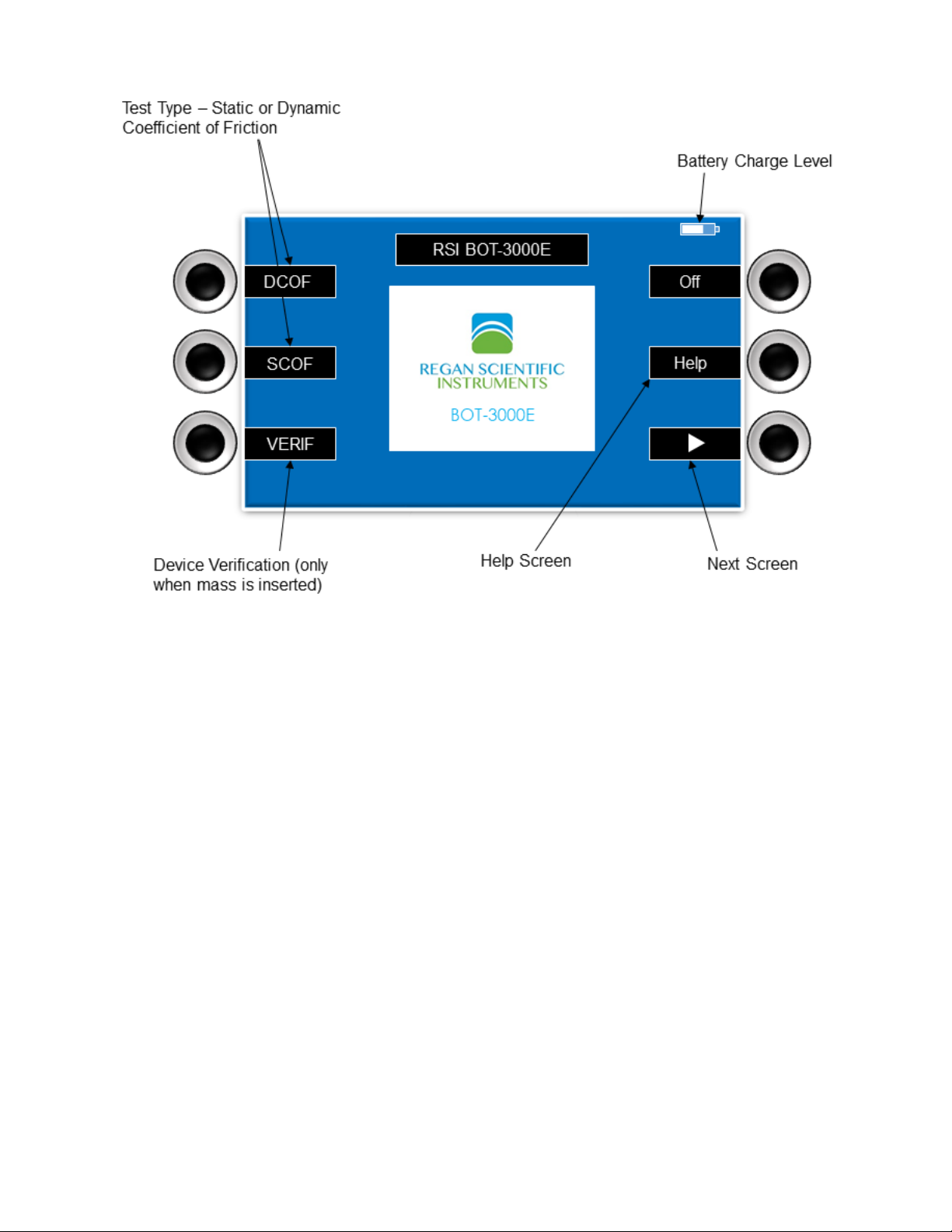
Figure 2
BASIC OPERATION
1. Insert a fully charged battery pack into the battery
compartment located at the front of the device. The latch
should engage to secure the battery pack to the device.
2. Tip the device onto either side or back panel and fully
insert the desired sensor (slider) into the receiver located in
the bottom of the device. Return the device to its operating
position (wheels down).
3. Center the device directly over the test area, noting the
approximate location of the sensor (side arrow labels).
When performing wet tests, be certain the sensor touches
down onto the applied liquid film. Avoid getting the wheels
wet, which could induce a wheel slip condition. Press any
switch momentarily to power up the device. There will be a
slight delay before the display illuminates.
6

4. Press the DCOF or SCOF switch according to the desired
test type (Fig. 2).
5. In DCOF mode, you may select “SINGLE” to perform one
test, otherwise select one of the Standard Test Methods
(Fig. 3).
USER TIP; It is often helpful to first perform a single pre-test
run which will help acclimate the sensor material to the surface
being tested.
Figure 3
6. Use the navigation switches (arrows, + and -) to adjust the
test run distance (DCOF ONLY), area, and location codes.
7. Press the “GO” switch to begin testing (Fig 4). The unit will
emit a beep alert, lower the sensor, and then move
forward. CAUTION: To protect the internal mechanism, do
not lift or move the instrument from the test surface until
the beep alert stops!
7

Figure 4
8. After each individual test run, a visual graph may be
displayed by pressing the “GRAPH” switch. Press the
switch again to return to the previous screen. NOTE: A
graph for each test run will be included in the pdf test result
file. These may be printed in hardcopy form from any PC or
MAC computer with a pdf (portable document file) reader
application.
9. Orient the device to each test starting position and
direction, then press the “GO” switch again. Repeat until all
fields are completed and the final result is indicated.
10. Press the “PRINT” switch to create a test result hardcopy
(data only).
11. The internally stored test data (with graphs and photos)
may be transferred to a USB flash drive by navigating to
“OPTIONS/USB”. To save download time, you may elect to
transfer only the test data collected since the LAST
download, or ALL of the stored test data. This may require
several minutes if there is a large amount of data stored.
You may also elect to DELETE all internally stored records
8

if desired. CAUTION: Do not remove the flash drive until all
data is transferred and a “DONE” message is indicated!
12. The maximum USB flash drive permitted is 8 GB. NOTE:
USB flash drives that do not conform to the strict USB
technical specifications may not be properly recognized by
the device.
13. The device may be powered down by pressing the “OFF”
switch located in the main menu screen.
ADDITIONAL TESTING FEATURES:
TEST TRACEABILITY CODES
Before testing, it is often useful to enter unique location
identification codes within an area that correspond to particular
test locations. These numerically coded identifiers can help
provide traceability to previously site-mapped areas, and will
appear on test results and reports.
Area Identification (AID) codes are used to help identify
physical buildings, facilities, or work sites, etc.
Location Identification (LID) codes are used to identify test
locations within each AID.
NOTE: You should change the AID or LID numbers periodically
so the system can properly store the maximum number of test
results (500 pdf reports). Internal memory should be deleted
periodically to maintain peak operating efficiency.
The fictitious “site map” example in Fig. 5 illustrates a simple
diagram of a small commercial kitchen area containing multiple
areas that are regularly tested. These test locations are identified
on the site map with text labels. Before running each test, the
screen will display the last AID and LID entered. These can be
easily adjusted using the up/down and +/- keys. There can be up
to 999 Area IDs, and 999 Location IDs within each AID.
9

Figure 5
Assigning unique AIDs and LIDs can be quite helpful in the
organization and monitoring of test results. Trends may be
tracked and potential remediations applied as needed. Site maps
can be sketched onto graph paper by hand or easy-to-use CAD
drawing programs such as Smart Draw™ can be used to create
impressive reports.
TEST LOCATION PHOTOGRAPHS
Photographic evidence of test location presence can be
provided within each saved test result file.
By default, a forward-facing photograph is taken in each 90
degree orientation when using a programmed test method.
Single run tests will have only one photo documented.
The camera may be disabled in the Device Settings menu.
10

SENSORS
The sensor, sometimes called a slider, is a key component of the
friction measurement system and must be maintained properly to
provide reliable test results.
Sensors must be kept clean, properly conditioned, and free of
damage. Flat spots and deep scratches in the lining material
must be avoided. A sensor reconditioning (sanding) tool is
available from Regan Scientific Instruments. This tool helps
maintain the radius of the sensor while removing scratches and
surface contamination. NOTE: Before using new sensors, they
must be sanded and checked until the reference surface target
value is reached. See Sensor Checking Procedure below.
Leather sensor material should always be kept dry, as moisture
may cause the leather to swell and become ruined.
Sensors can be relined with new material by Regan Scientific
Instruments for a nominal fee if ruined or when worn to less
than 2mm in thickness.
STANDARD SENSOR TYPES AND COLORS
LEATHER – RED COLORED BODY
SBR RUBBER – BLACK COLORED BODY
NEOLITE – YELLOW OR GOLD COLORED BODY
CUSTOM – BLUE OR GRAY COLORED BODY*
*Custom sensors can be fabricated by Regan Scientific Instruments for a
nominal fee. The material provided must be at least 28mm X 28mm in size
and between 2mm and 5mm in thickness.
SENSOR SANDING PROCEDURE
1. Use fresh sandpaper with each new test location. Thoroughly
brush the sandpaper to remove any loose sand particles from
the paper.
2. Insert the sensor and sand until any noticeable wear pattern
or flat spot has been removed.
11

3. Remove sensor and wipe off debris with a clean, lint free, oil
free paper towel or clean brush.
4. Thoroughly brush all the debris from the sand paper.
5. Re-insert the sensor and sand for 10 more revolutions.
SENSOR CHECKING PROCEDURE
1. Tip the device onto either side or back panel and fully insert a
freshly sanded and cleaned sensor into the sensor receiver
located in the bottom opening of the device. NOTE: When
sanding or reconditioning the sensor material, it is highly
recommended to wear a filtered mask to avoid breathing in
any fine dust or particles generated during the process.
2. Using a small clean paint brush, apply a continuous film of the
appropriate lubricant completely down the center of the
reference surface approximately 3 inches wide. The reference
surface label (bottom) should indicate the type of lubricant
(e.g. distilled water) for each sensor as well as the expected
result.
NOTE: The optional leather sensor should never become
dampened or wet. It should be run only on completely dry
surfaces or they may become permanently ruined.
3. Return the device to its operating position (wheels down)
centered over the reference surface, with the rear edge
approximately even with back edge of the tile as shown below
(Fig.6). Arrows on the sides of the device indicate the
approximate front-to-back location of the sensor. NOTE: This
operation should be conducted on a hard, level, flat surface
and never over carpet.
12

Figure 6
4. Adjust the test run distance to 8 inches (20 cm), run two
DCOF tests in opposing directions, then average both results.
Compare the averaged result to the reference surface label
target value. If the value falls within the stated tolerance band,
the sensor is conditioned and ready to perform testing.
5. If the resulting averaged value falls outside the stated
tolerance band, the reference surface may require additional
cleaning, or the sensor may require further reconditioning with
new sandpaper. The reference surface should be polished
periodically with 12 micron lapping film to remove invisible
contamination buildup.
6. As an optional feature, a sensor may be programmed to
incorporate a limited positive or negative offset value to
compensate for minute differences in the sensor material,
determined by a known reference surface value. The default
setting for this feature is disabled. NOTE: If an offset value is
used, the value will be included in the test result data printout.
13

PRINTING
Hardcopies of the most recent test results, calibrations, and
verifications may be obtained from the “PRINT” screen, or
immediately following a test run (Fig.7).
When the thermal paper roll becomes depleted, it may be
easily replaced by gently squeezing the plastic tabs located
on each side of the access cover, and then gently pulling the
hinged cover open. Be sure to remove the plastic core from
the depleted paper roll. A new roll may be dropped in with
the loose end facing up and outward. Allow a small amount
of paper to protrude from the printer while gently closing the
access cover until it snaps closed.
Extra thermal paper may be obtained from Regan Scientific
Instruments, online retailers, or from various office supply
stores. The paper roll must be 2 ¼” wide, and less than 50 ft.
in total length to fit the printer. Larger diameters rolls may
damage the printer! NOTE: Most thermal printer paper
printouts will fade or darken over time.
Figure 7
14

DEVICE MAINTENANCE
The BOT-3000E requires a minimum amount of maintenance as a
function of design, however there are several items that should be
noted:
BATTERIES:
Battery packs should never be transported or stored where
metallic objects or liquids may contact the connection interface
or it could arc and ignite any surrounding material.
Leaving a battery pack inside the device or the charger when
not in use will drain the pack to an unusable state.
Battery packs should be maintained on a rotating charging
schedule to prevent premature failure.
Battery pack charging should take place in an open area free
from excessive heat, dust, and flammable gasses or liquids.
Batteries may become quite warm during charging, and must
be allowed to cool completely before using.
WHEELS:
Wheels may be removed for cleaning by pushing the hub
inward and turning 90 degrees. The wheel should now be
easily separated from the axle. The wheels should be cleaned
with isopropyl alcohol, using a toothbrush, followed by a clean
water rinse. Dry wheels completely before reinstallation.
CALIBRATION:
The user may not calibrate the device; it MUST be returned
to Regan Scientific Instruments to receive an authorized
factory calibration on a specially designed calibration fixture.
The device will indicate the last calibration date with the
printed test results. The calibration cycle is on an annual
basis, regardless of the usage amount. Please make note of
15

the last calibration date, as it will become due exactly one
year from that date.
GENERAL NOTES
Each switch press may be followed by a short delay before
the desired action is initiated.
When the device is inactive for a certain time period, the
display will dim. A press of any switch will awaken the
device. After an extended period of inactivity the device will
beep several times, then power down to conserve battery
pack life. Previous test results will be saved.
It is recommended that one dedicated flash drive be used
per each BOT device, to avoid the possibility of overwriting
files created by another device.
The battery pack charger indicator illuminates red during the
charging cycle, and will change to green once the battery
pack is fully charged. The charger may fault if a battery pack
becomes overheated. In this situation, remove the battery
pack from the charger and allow it to cool down completely
before charging again.
Many types of textured or profiled floors can be tested
without problems; however there may be occasional
surfaces that can be quite challenging. These may be in the
form of grates, embossed metal plates, mosaic tiles, random
or patterned textured surfaces often found near pools, spas,
patios, ramps, etc. See Fig. 8 for examples of limitations.
Reconditioning the sensor material manually is not generally
recommended. Using the Regan Scientific Instruments
sensor reconditioning tool may greatly reduce irregular
sanding patterns or techniques.
16

Figure 8
NOTE: If a third party reference surface was provided for use
with a specific standard test method, then the procedure from
the provider should be followed.
Whenever squared edge type surfaces (e.g. mosaic tiles),
are to be tested, a best practice is to orient the device to
traverse the edges at or near 45 degrees. This will make the
transition between tiles smoother.
The supplied reference surface can eventually become worn
or soiled with sensor material, minute particles, dried SLS, or
fingerprints. It is advisable to clean it occasionally with
Bona™ Stone, Tile and Laminate floor cleaner, which is
available from many retail stores. Dry the surface with plain
white paper towels ONLY, as some paper towel products are
treated with lint reduction agents, and could affect the
measurement results of the surface. The reference surface
should be polished periodically with 12 micron lapping film to
remove invisible contamination buildup.
17

TEST RESULTS REPORTING
Fig. 9 (next page) illustrates a typical device-generated report for
the ANSI A326.3 Standard Test Method (field/dry, sheet one of
three only). The report lists the four required measurements (per
the test method.) The photos are often helpful for positive
identification of particular test areas (e.g. in front of a doorway or
staircase). Each graph represents one measurement of the set.
Graphs can be useful in determining the degree of surface
variation for a given area. The average DCOF value for each
measurement is the recorded result. The median of the four
averages is the final test result. Single SCOF or DCOF tests will
display one measurement per report. Other test method reports
may be formatted differently than the illustrated example. Test
report folders are created first by the device serial number, the
test date, and then the area ID. The pdf files are arranged by
Date/AID/LID/test sequence. The DATA.LOG test data files are
stored in a folder created under the test date/area ID. These data
files may be renamed to DATA.TXT or DATA.CSV for importing
into various spreadsheet programs.
18

Figure 9
19

NOTE: The camera may be disabled in DEVICE SETTINGS if
photos are not desired in the report, however the graphs will
always remain visible as part of the test results report.
MORE ABOUT DATA.LOG FILES
Stored data files (not pdf files) contain test information in text
format which can be imported into spreadsheets or other text
input programs. This can be useful for tracking events or
analyzing trends. The structure of the logged data is
demonstrated below:
08/21/17, 8:34AM,001,002, ,DCOF ,,,0.35,,,,,
08/17/17, 2:52PM,004,001,3,A326.3,Field/Wet,Prevailing,0.38,0.36,0.42,0.34,0.41
08/17/17, 2:48PM,003,001, ,A137.1,,,0.42,0.43,0.44,0.40,0.41
The DATA.LOG file structure is as follows:
Date, Time, Area, Location, [Sample no.], Standard / Test
method, Test type, Condition, Average, Meas.1, [Meas. 2], [Meas.
3], [Meas. 4], PDF filename
NOTE: Items in brackets above are not included with single
DCOF or SCOF tests.
The PDF file naming convention is MMDDCCCC.pdf where MM is
the month, DD is the day of the month, and CCCC is the counter.
The various data log files may be viewed directly on the device
data screen, or be transferred to a USB flash drive and then
loaded into a PC for archiving or analysis. NOTE: A limited
number of data log files may reside in the device memory after
the pdf test files have been transferred or deleted.
20

BOT3000E On-Screen Messages
"ABORTED BY USER" - Measurement stopped by user.
"ARCHIVE DELETED" - Deleting of archive complete.
"ARCHIVE xxx of yyy" - Archiving files that have been transfered to USB.
"BLUETOOTH TRANSFER" - Transfering data or files via bluetooth.
"CALIB. DUE IN xxx DAYS" - Calibration expiration approaching.
"CALIB. PAST DUE xxx DAYS" - Calibration past due.
"CAMERA COMM FAILURE" - Unable to communicate with camera.
Return to factory for repair
"COMMAND FAILED" - Couldn't communicate with slider crypto chip.
"CREATING REPORT" - Creating A326.3 PDF report.
"DEAD BATTERY" - Battery is essentially dead. Unit will turn itself off.
"DELETING ARCHIVE" - Deleting files from archive.
"DELETING xxx of yyy" - Deleting files from archive.
"DETACHING USB" - Un-installing USB stick after removal.
"DO NOT REMOVE USB" - USB in use, do not remove.
"ERROR: DELTA > 0.06" - Slider offset out of range.
"FILE ERROR" - Unable to create the PDF.
"INCOMPLETE xxx of yyy" - Error in the transfering of files to USB.
"INSERT SLIDER" - Tried to take a measurement without a sensor inserted.
"INSTALLING USB" - USB was detected and is being initialized.
"INVALID SLIDER" - Wrong sensor type for selected standard.
Insert the correct sensor for the desired test method
"LOADING DATA" - Loading previously saved A326.3 data.
"LOW BATTERY" - Battery is low but will still take a measurement.
"MAIN DETECT ERROR" - Unable to communicate with crypto on main board.
"MEAS. TIMEOUT" - Measurement did not complete in time (likely because unit did not drive
forward)
"NO DATA TO PRINT" - No measurements have been taken to print.
"NO FILE SYSTEM" - Unable to detect internal file system.
"NO USB STICK" - No USB stick inserted.
"OUT OF PAPER" - Printer out of paper.
"PRINTER ERROR" - Unable to communicate with printer.
21

"PRINTING" - Printer is currently printing.
"RE-INSERT SLIDER" - Unit detects slider but cannot read crypto chip.
Remove sensor and clean contacts, cycle power off/ on. Replace sensor if needed
"RECHARGE BATTERY" - Battery is too low to take a measurement or print
"REMOVE MASS" - Alert to remove verification mass
"ROTATE 90 DEGREES" - Instruction during standard testing
"RTC CLOCK FAILURE" - Real time clock is malfunctioning
Cycle power off and on; Return to factory if condition does not resolve itself
"SERVICE NEEDED" - Lift sensor malfunctioned
"SET DATE/TIME" - Clock is set to date prior to software compile date
Set time / date in “Device Settings”
"SHUTTING DOWN" - Warning that the unit is about to turn itself off
"SYSTEM NOT READY" - System is busy and cannot currently process user request
Pause for 1 second before switching functions
"TURNING OFF" - Off button pressed, unit about to turn off
"TXFRING xxx of yyy" - Transfering files to USB
"UNIT NOT LEVEL" - Unit not level during verification
Move device to level surface
"USB INSTALL FAILED" - Could not initialize USB stick
Replace USB flash drive
"WARNING xxx mm/s" - Measured speed out of range
Test surface too steep
"WHEELSPIN" – Wheel spin detected during measurement
Remove, clean, and dry wheels / tires – check orientation on hub
Surface friction too high to overcome
22

TECHNICAL DATA
Device dimensions: 29 x 20 x 17cm
Weight: 6.8 Kg
Measurement velocity (DCOF): 20cm/s ± 5%
Measurement range: 0.01 to 1.00 DCOF
Measurement normal force: 22.4N ± 2%
Contact patch: approx. 3mm X 28mm
Measurement system tolerance: 3%
DCOF measurement distance: 10 to 50cm, incremental by 5cm
(displays 4” to 20”)
Ramp angle: 9.6 degrees maximum (declination)
Verification Mass: 1.36 Kg
Operating/Storage Temp: 5 - 40 deg. C
Operating/Storage Humidity: 5 - 90% RH (non-condensing)
Internal Memory: 1000+ measurements
Display: 480 x 272 LCD TFT display with 262K colors, LED backlit
Test data storage/transfer: USB flash drive, 8MB max.
Transferred file formats: PDF, TXT/CSV (.LOG files)
Printer: Thermal, 48 mm wide, 8 dots/mm
Processor type: ARM Cortex M4 32 bit processor, 120 MHz
Sampling rate: 1000 samples / sec
Protection class: IP20
Power source: RSI battery pack (NiMH battery, 12V nominal,
3.8Ah)
Battery pack charger: 120-240VAC 50/60 Hz input, UL listed
23

WARNING: There are no user serviceable components
inside the tribometer, battery pack, or charging unit, and
they should NEVER be opened for any reason, except by
Regan Scientific Instruments or an authorized agent.
FREQUENTLY ASKED QUESTIONS
Q – Why does the device require annual calibration when
we hardly use it?
A – Any laboratory-grade measurement instrument should
be calibrated on a regular period determined by the
instrument manufacturer. ISO 9001:2008 promotes this
policy. Most manufacturers of this type of measurement
instrument require calibration on a frequency of at least
once per year, regardless of the usage amount.
Q – Why can’t the device be shipped with a battery pack
installed?
A – Air Transportation agencies have ruled that electronic
devices should have the batteries removed so they cannot
activate during shipment and potentially cause
interference with navigation or communication equipment.
Also, when a battery pack is installed in a device or a
charger, a small amount of energy is constantly drained.
This can eventually lead to a dead battery pack.
Q – Why is my reference surface reading too low?
A – This may be caused by using worn sandpaper, or a
reference surface that has accumulated surfactant levels
(SLS build-up) over time. Replace the sandpaper often
and clean the reference surface properly.
Q – Can you replace worn or damaged sensors?
24

A – Yes, we can replace the sensor material for
approximately half the cost of a new sensor. Please visit
our website (see cover) for pricing, availability, shipping,
and other information.
Q – What does “Wheel Slip Error” on the display indicate?
A – The wheels should be kept dry during operation to
provide adequate traction. They may need to be removed
and cleaned if they have picked up contamination.
Q – Can the device run across tile grout joints during a
DCOF test?
A – Most properly installed tile floors will have grouted
joints between flat level tiles, and are traversable, as long
as the device crosses the joints at an angle of
approximately 45 degrees. The test run distance may be
adjusted to fit within most single tiles. Avoid running
across uneven, raised tile edges that protrude above the
normal surface plane, as the sensor could catch on the
raised edge.
Q – Why should I utilize a Standard Test Method?
A – Different testing methodologies often produce quite
different results due to the number and degree of
variables. Standard Test Methods are designed to apply
controls and limits, therefore allowing test results to be
used within a context or framework of acceptable and
unacceptable levels of risk.
The current time and date, along with other device settings,
may be edited by navigating to OPTIONS/DEVICE/ DEVICE
SETTINGS. The “SAVE” switch must be pressed when
completed.
25

Product Warranty and Disclaimer
One year parts and labor, excluding normal wear and tear parts
such as sensors, batteries, tires or any physical damage. Any
warranty exclusion is solely determined by Regan Scientific
Instruments, Inc. Defective products or materials may be repaired
or replaced at our discretion. We reserve the right to make
changes to product designs and specifications without providing
notice.
Limitations on Liability
BUYER SHALL NOT IN ANY EVENT BE ENTITLED TO, AND
SELLER SHALL NOT BE LIABLE FOR INDIRECT, SPECIAL,
INCIDENTAL OR CONSEQUENTIAL DAMAGES OF ANY
NATURE INCLUDING, WITHOUT LIMITATION, BUSINESS
INTERRUPTION COSTS, REMOVAL AND/OR
REINSTALLATION COSTS, REPROCUREMENT COSTS, LOSS
OF PROFIT OR REVENUE, LOSS OF DATA, PROMOTIONAL
OR MANUFACTURING EXPENSES, OVERHEAD, INJURY TO
REPUTATION OR LOSS OF CUSTOMERS, EVEN IF SELLER
HAS BEEN ADVISED OF THE POSSIBILITY OF SUCH
DAMAGES. BUYER'S RECOVERY FROM SELLER FOR ANY
CLAIM SHALL NOT EXCEED BUYER'S PURCHASE PRICE
FOR THE PRODUCT GIVING RISE TO SUCH CLAIM
IRRESPECTIVE OF THE NATURE OF THE CLAIM, WHETHER
IN CONTRACT, TORT, WARRANTY, OR OTHERWISE.
SELLER SHALL NOT BE LIABLE FOR AND BUYER SHALL
INDEMNIFY, DEFEND AND HOLD SELLER HARMLESS FROM
ANY CLAIMS BASED ON SELLER'S COMPLIANCE WITH
BUYER'S DESIGNS, SPECIFICATIONS OR INSTRUCTIONS,
OR MODIFICATION OF ANY PRODUCTS BY PARTIES OTHER
THAN SELLER, OR USE IN COMBINATION WITH OTHER
PRODUCTS.
26

Warranty Disclaimer
We (seller) make no representations about the suitability of
the products for any purpose. In no event shall we be liable
for any special, indirect or consequential damages or any
damages whatsoever resulting from loss of use, data or
profits, whether in an action of contract, negligence or other
tortuous action, arising out of or in connection with the use
or performance of the products it sells. We assume no
responsibility for errors or omissions in this publication or
other documents which are referenced or linked to this
publication; nor do we make any commitment to update the
information contained herein. This publication and other
documents, and prices are subject to change without notice.
We are not responsible or liable for any injuries, damages, or
death caused by the use, misuse or failure of products
purchased from us, nor from the use of any other materials,
articles, or other published information.
© 2008 - 2018 Regan Scientific Instruments Inc.
1628 Valwood Parkway Suite 200
Carrollton, Texas 75006 USA
All rights reserved
27
 Loading...