

Page 1

Easy Open Extra Wide Gate
MODEL NO: 1185
Owner’s Manual
11/22/2013_BL
READ ALL INSTRUCTIONS BEFORE ASSEMBLY
AND USE OF GATE.
KEEP INSTRUCTIONS FOR FUTURE USE.
www.regalo-baby.com
...........................................................................
Regalo International, LLC.
3200 Corporate Center Drive, Suite 100
Burnsville, MN 55306-9803, USA
Toll Free: 866-272-5274
Made in China
Page 2
Assembly and Installation Instructions
Please read these instructions carefully before installing your gate.
WARNING:
Intended for young children aged 6 months through 24 months.
Check the gate regularly to see if all the hardware and mountings
are tightened.
To prevent serious injury or death, securely install gate or
enclosure and use according to manufacturer’s instructions.
Never use with a child able to climb over or dislodge the gate or
enclosure.
Never leave child unattended.
Use only with the locking/latching mechanism securely engaged.
Please follow these instructions carefully to ensure that your gate
extension is properly installed. Improper installation could result in
the gate becoming dislodged from the doorway, or unstable.
Always make sure the extension is securely attached to the gate
before using. The safety of your child is your responsibility.
Note:
If using this gate at the top of stairs,the 4 Wall Cups MUST
be used . If not use,the gate could be dislodged from the opening.
It is preferable to install the extension on the hinge side of the gate.
If you have an application that requires additional extensions,please
contact the retailer which you purchased your gate from.
This gate can be used in openings from 29 inches to 50 inches.
Contact Regalo for questions and replacement parts.
If in doubt about the use of your gate, call our customer care line 866-272-5274.
Regalo International, LLC.
3200 Corporate Center Drive,Suite 100
Burnsville, MN 55306-9803, USA.
Made in China
Page 3
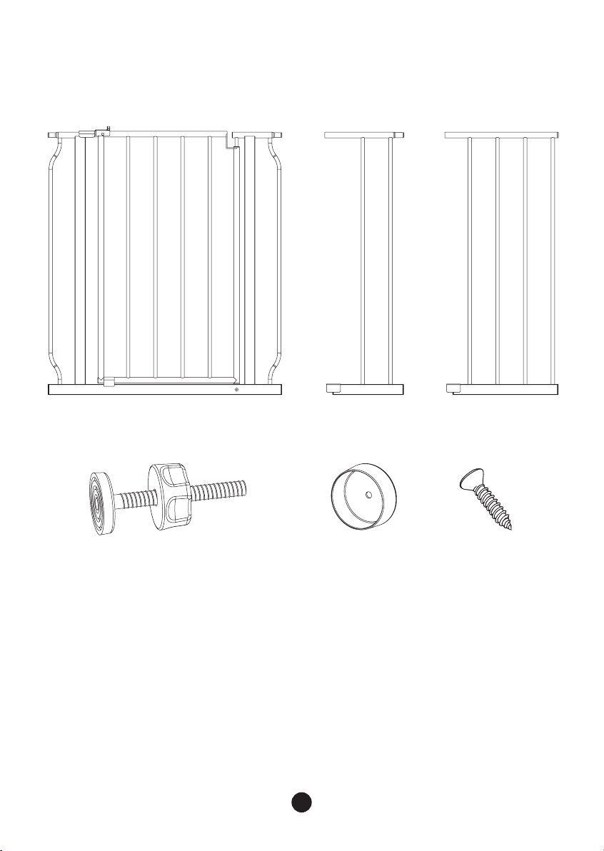
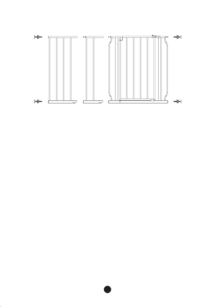
Check to make sure you have all of the parts shown:
D. E. F.
A.
Easy Open Gate
B.
6” Extension
C.
12” Extension
D.
4 Threaded Spindle Rods
E.
4 Wall Mounting Cups
F.
4 Screws (requires a Phillips/crosshead screwdriver)
1
B.A.
C.
Page 4

Assembling and Installing Your Gate
**Note: IMPORTANT!! You will notice a slight gap between the gate door and the gate
frame. THIS IS NOT A DEFECT. Your gate is a pressure mounted gate and this gap will
disappear once you tighten your gate in its opening.
Step 1.
Locate the 4 threaded spindle rods. Rotate the adjustment wheels along the threading,
eliminating the gap between the adjustment wheel and the rubber foot.
Threaded Spindle Rod
Diagram A
Adjustment Wheel
Rubber Foot
Step 2.
Insert the 4 threaded spindle rods into the holes at each of the 4 corners of the gate as
shown in the Diagram
Diagram B
2
Page 5
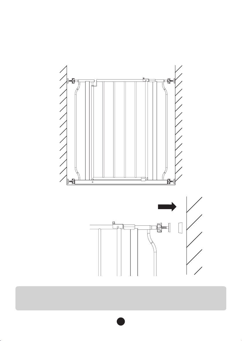
Step 3.
Position the gate so that it is level and centered within your doorway or opening.
Rotate the adjustment wheels on the threaded spindle rods in the opposite direction
as in Step 1, expanding the gap between the rubber foot and the adjustment wheel.
Expand each of the 4 Threaded Spindle Rods until they make contact with the
doorway or opening. Do not fully tighten the Threaded Spindle Rods yet.
Diagram C1
Diagram C2
HINT:
It may be necessary to hold the Threaded Spindle Rods or Rubber
Feet while rotating the Adjustment Wheels to ensure the entire
unit does not rotate.
3
Page 6
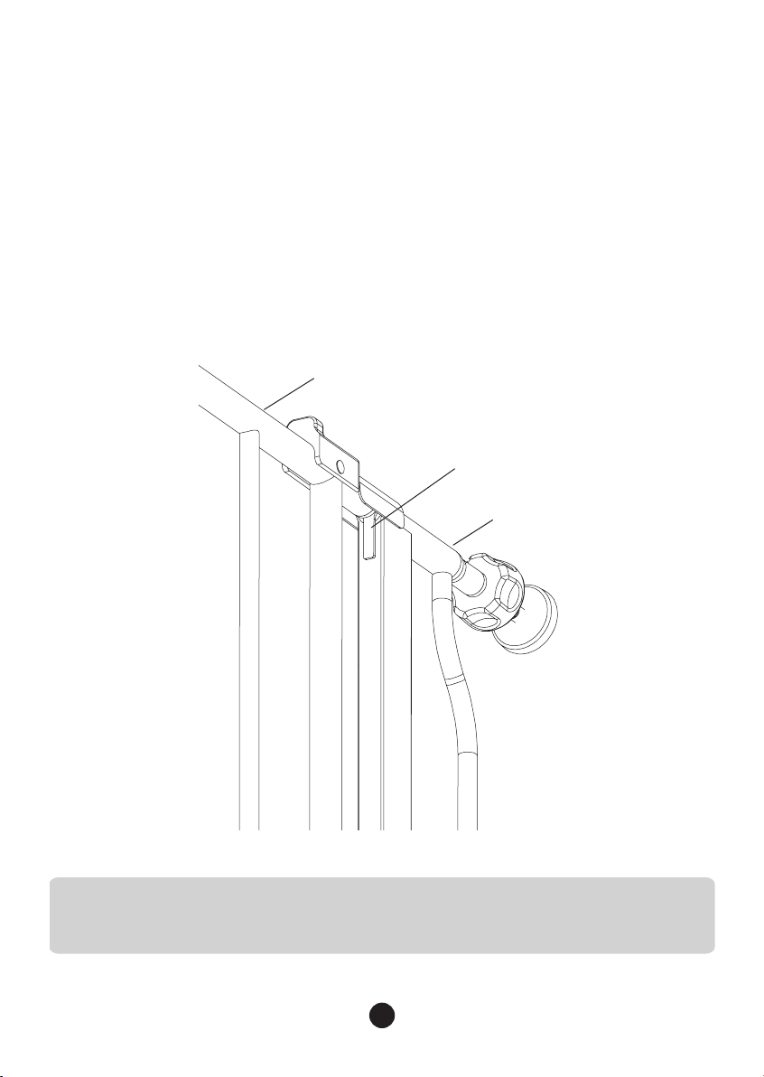
Step 4.
When you are satisfied with the general placement of your gate, fully tighten
the Threaded Spindle Rods attached to the lower corners of the gate by
further rotating the Adjustment Wheels.
Continue by tightening the upper Threaded Spindle Rods. As you tighten the
upper Threaded Spindle Rods, you will notice the gap between the Door
Frame and the door begin to narrow.
In order for the gate to function properly, tighten the upper Threaded
Spindle Rods completely without removing the Plastic Lock Spacer. Then,
pull the Thumb Lock back to remove the Plastic Lock Spacer. This will ensure
proper spacing between the door and frame.
Door
Plastic Door Spacer
Frame
Diagram D
NOTE:
There should be equal spacing among each of the 4 Threaded
Spindle Rods. Make the appropriate adjustment to ensure you
have installed your gate safely.
4
Page 7
Positioning and Attaching the Wall Cups
Your gate is a pressure mounted gate. Therefore, it is not necessary to use the screw
attached Wall Cups in your door opening if you choose not to. However, IF YOU ARE
USING THE GATE AT THE TOP OF STAIRS YOU MUST USE THE WALL CUPS. Using the
Wall Cups will affix your gate more firmly in the doorway or opening.
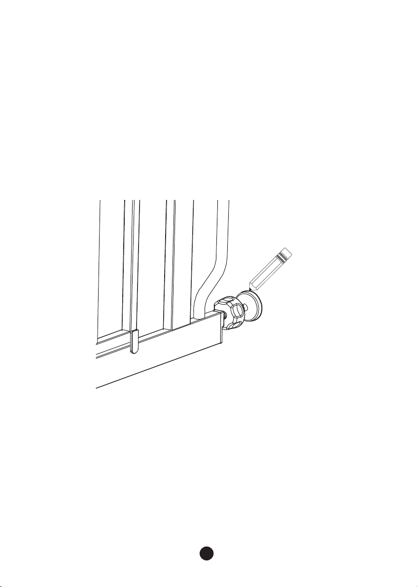
Step 1.
After you have mounted your gate, and you are satisfied with its positioning, use a
pencil or other marking tool to draw a circle on the surface of your doorway or
opening around the perimeter of the 4 rubber feet.
Diagram E
Step 2.
Next, completely remove the gate from the opening by loosening each of the 4
Threaded Spindle Rods and de-pressurizing the gate.
5
Page 8
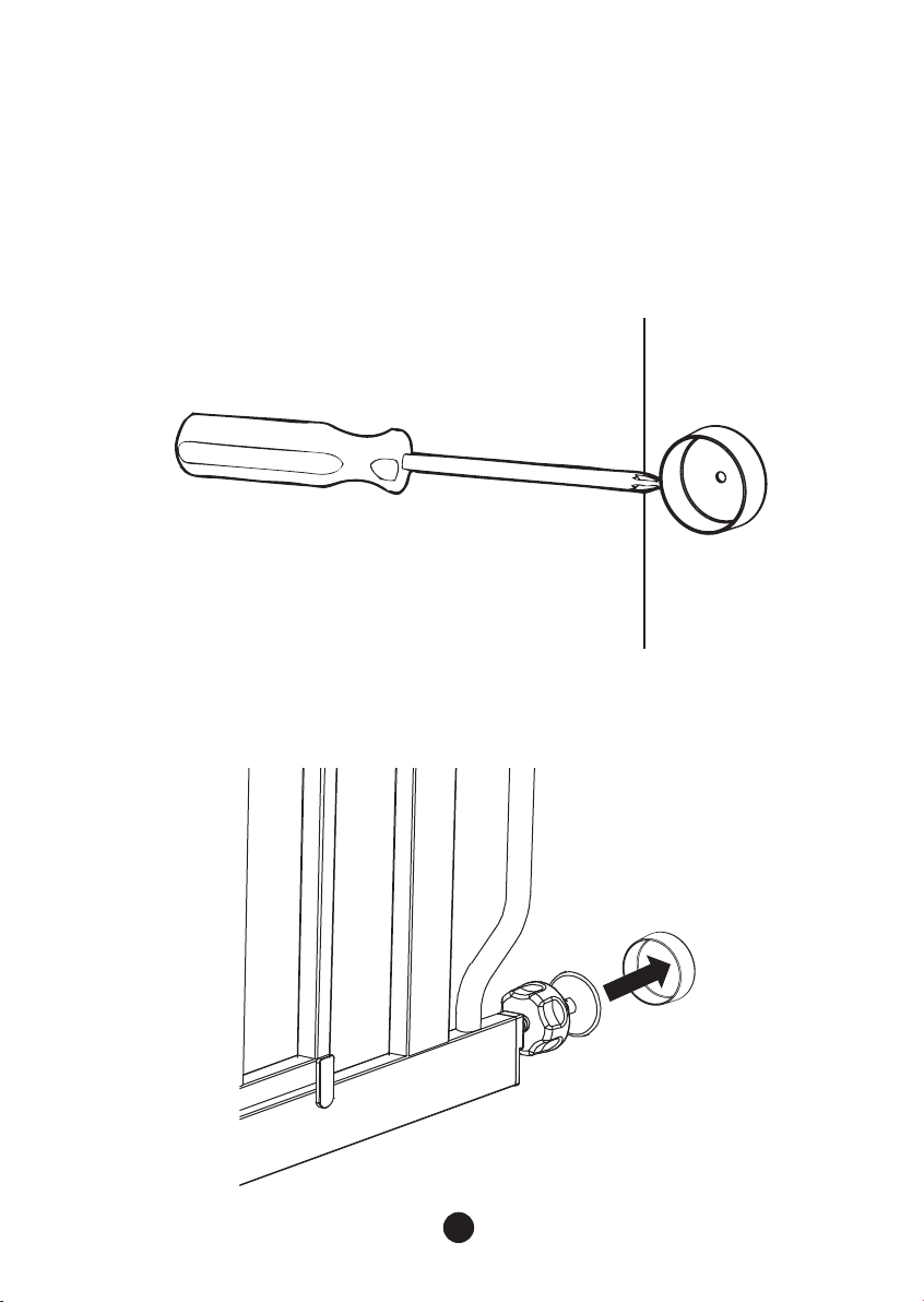
Step 3.
With the gate fully removed, you can now use the circles you marked during Step 1
as guides for screwing in your 4 Wall Cups.
Center each of the Wall Cups within the guide circles and use the provided
self-tapping screws to fasten them in place via the hole through the center of each
Wall Cup.
Diagram F
Step 4.
Reinstall your gate in the doorway or opening according to the instructions, using
the newly installed Wall Cups as anchoring points for the 4 Threaded Spindle Rods
Diagram G
6
Page 9
Operating the Door Latch
Step 1.
Use your thumb or forefinger to pull back on the Thumb Lock. This action will
release the locking pin below the metal saddle that joins the door and the
gate frame.
Step 2.
With the Thumb Lock pulled back, lift up on the entire door panel, raising the
gate high enough for the upper and lower metal saddles to clear free of their
counterparts. Your gate door should now be free to fully open. To close the
gate, simply repeat these steps in reverse.
HINT:
If your latch is not properly engaging, ensure that your gate is
level, mounted properly, and that you have not over-tightened
the Threaded Spindle Rods.
7
Page 10
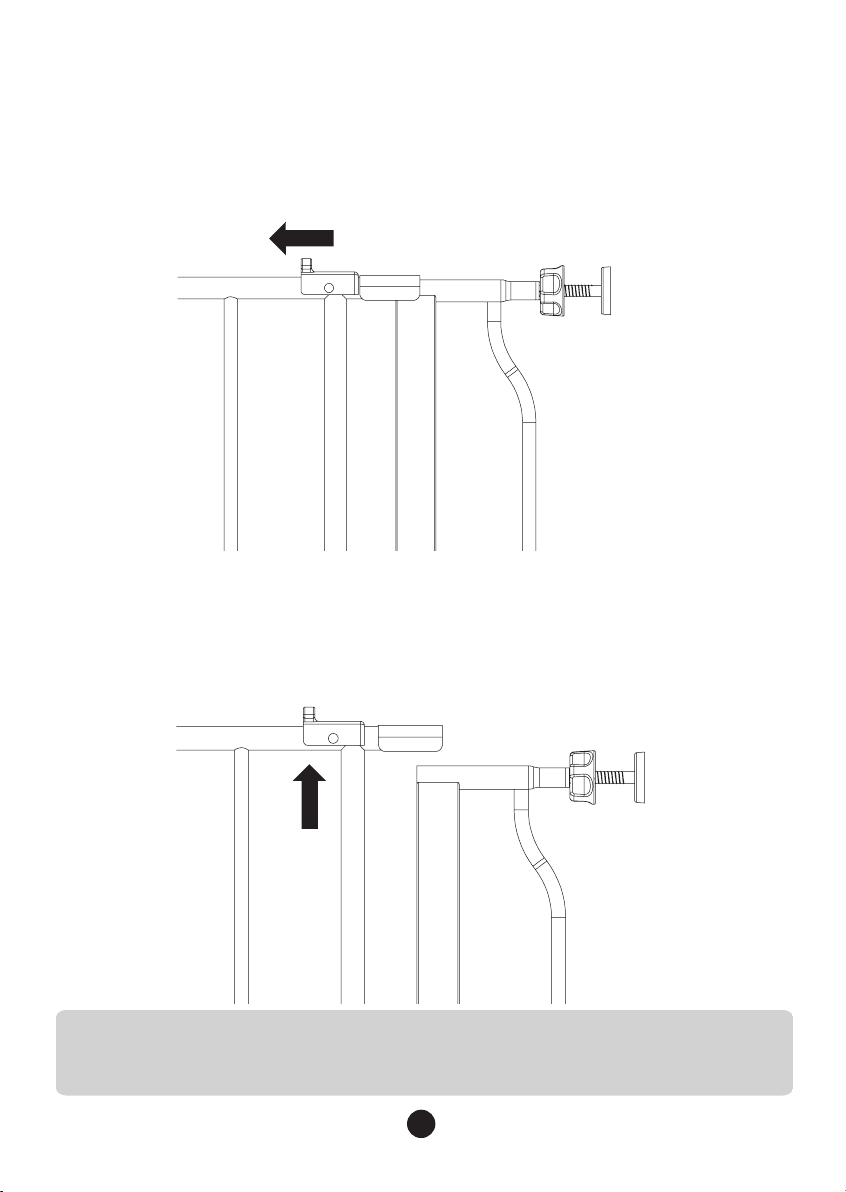
Adding a Gate Extension
Step 1. Assemble the gate per the gate instructions.
Step 2. Choose the side of the gate to be extended and remove the top
and bottom Threaded Spindle Rods.
Step 3. Assemble the gate and extension as illustrated.
Step 4. Reposition the gate and fit in accordance with the gate fitting
instructions.
Removing Your Gate From The Wall
To remove your gate from the wall, rotate the Adjustment Wheels on
each of the 4 Threaded Spindle Rods to depressurize the gate from its
doorway or opening. Then, gently pull or push the gate free from its
doorway or opening.
Care And Maintenance
Periodically check the gate for signs of damage, wear, or missing components.
Do not use if any part is missing, worn or damaged. Check the gate regularly to
ensure all the hardware and mountings are tightened. Do not use abrasive
cleaners or bleach. Clean by sponging with warm water and a mild detergent.
90 Days Limited Warranty:
If, during the first 90 days after consumer purchase of the item, under
reasonable and non-commercial use and conditions of maintenance, it fails
while owned by the original purchaser because of the quality of materials or
workmanship of finish and assembly, Regalo International LLC will replace or
repair it at Regalo’s option. PROOF OF PURCHASE REQUIRED.
8
Page 11
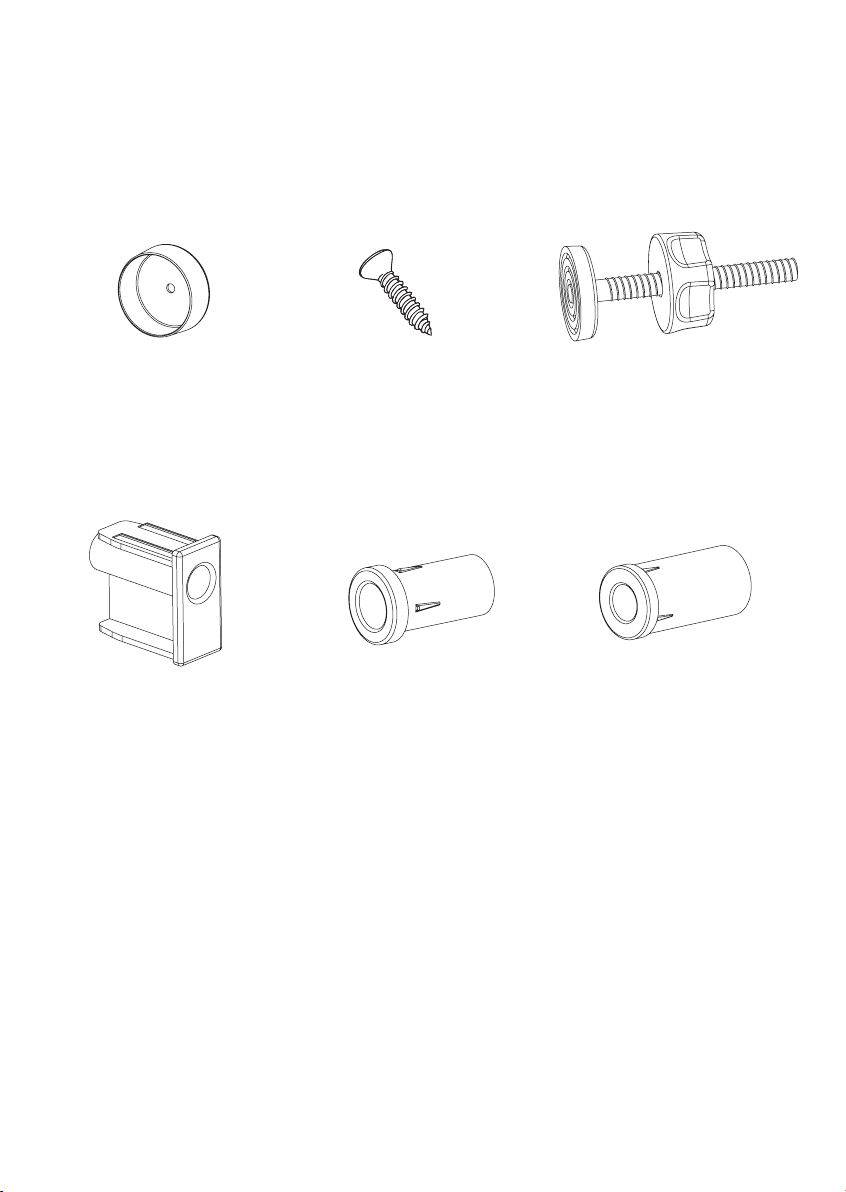
Replacement Parts Available
In the event of any damage or breakage, the following replacement parts
are available for order by contacting Regalo Customer Service.
Wall Cups
(#14015)
Bottom Plug Insert B
(#14041)
1” Wall Mount Screws
(#10001)
Tapered Round Insert
(#14042)
Threaded Spindle Rods
with Adjustment Wheel
(#14016)
Untapered Round Insert
(#14043)
Contact Regalo for questions and replacement parts.
For questions about the use of your gate, call our customer care line 866-272-5274.
Regalo International, LLC.
3200 Corporate Center Drive, Suite 100
Burnsville, MN 55306-9803, USA
Made in China
Page 12

Regalo International, LLC.
3200 Corporate Center Drive, Suite 100
Burnsville, MN 55306-9803, USA
Toll Free: 866-272-5274
Made in China
11/22/2013_BL
 Loading...