

Version 4 (No. 982065) 801 Series June 2019
Operating Instructions
REFUone 3K-2T ... 7K-2T

REFUone 3K-2T, 5K-2T, 7K-2T
2
Notice
This manual contains important safety instructions that must be followed during installation
and maintenance of the equipment.
Save these instructions!
This manual must be considered as an integral part of the equipment, and must be available
at all times to everyone who interacts with the equipment. The manual must always
accompany the equipment, even when it is transferred to another user or field.
Copyright Declaration
The copyright of this manual belongs to REFU Elektronik GmbH. Any corporation or individual
should not plagiarize, partially copy or fully copy it (including software, etc.), and no
reproduction or distribution of it in any form or by any means. All rights reserved.
REFU reserves the right of final interpretation. This manual is subject to change according to
user’s or customer’s feedback. Please check our website at
http://www.refu.com
for latest
version.
REFU Elektronik GmbH
Marktstraße 185
D-72793 Pfullingen
Tel.: +49 (0)7121-4332 0
Fax: +49 (0)7121–4332 140
Mail: info@refu.com
REFUone 3K-2T …7K-2T
3
Preface
Outline
Please read the product manual carefully before installation, operation or maintenance. This
manual contains important safety instructions and installation instructions that must be
followed during installation and maintenance of the equipment.
Scope
This product manual describes the installation, electrical connections, commissioning,
maintenance and troubleshooting of REFUone 3K-2T … 7K-2T inverters.
Keep this manual where it will be accessible at all times.
Target Group
This manual is intended for qualified electrical technical personnel who are responsible for
inverter installation and commissioning in the PV power system and the PV plant operator.
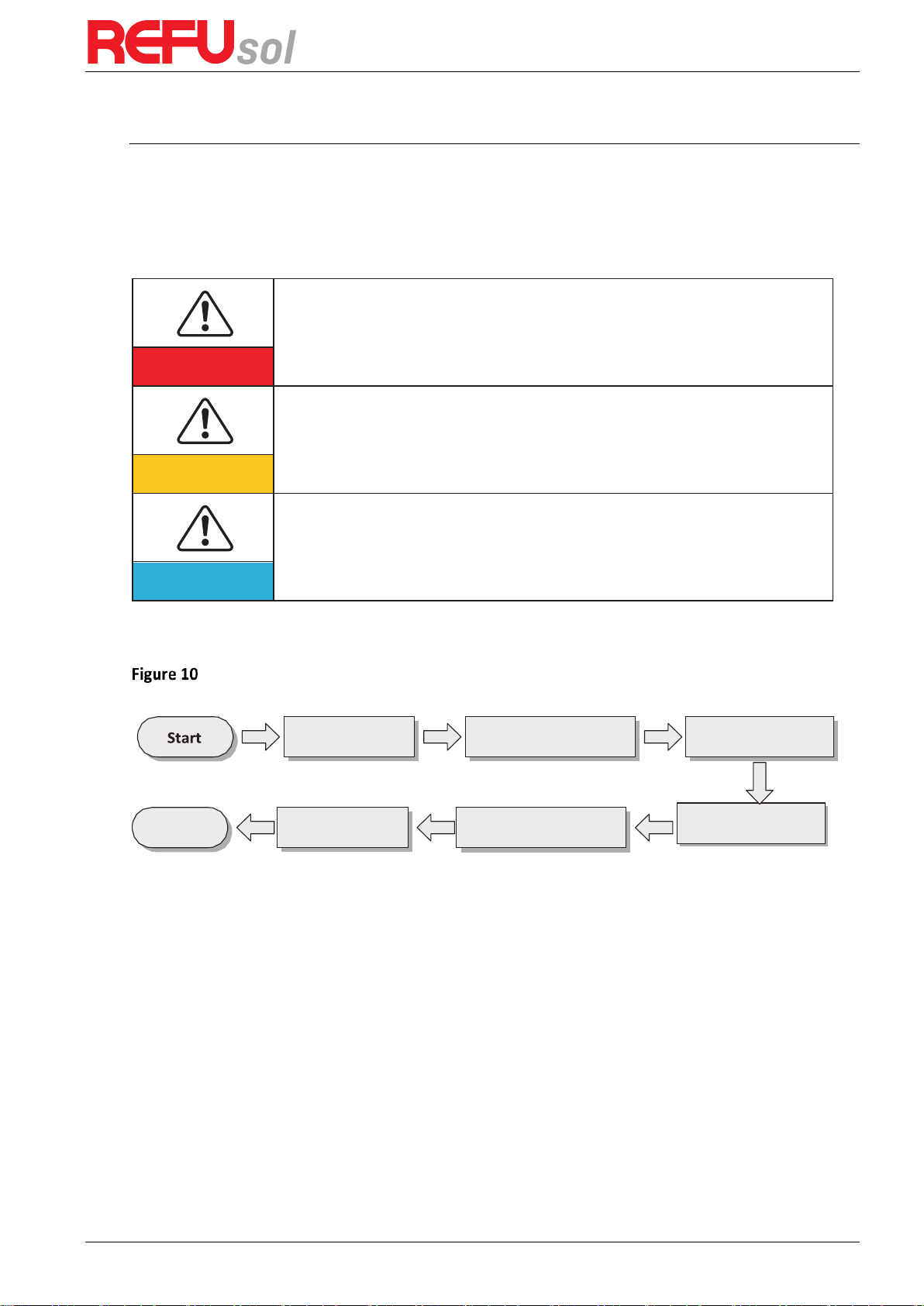
Symbols Used
This manual provides safety operation information and uses the symbol in order to ensure
personal and property security and use the inverter efficiently when operating the inverter.
You must understand these emphasized information to avoid the personal injury and property
loss. Please read the following symbols used in this manual carefully.
Danger indicates a hazardous situation which, if not avoided, will result in death or
serious injury.
Danger
Warning indicates a hazardous situation which, if not avoided, could result in death or
serious injury.
Warning
Caution indicates a hazardous situation which, if not avoided, could result in minor or
moderate injury.
Caution
Attention indicated potential risks which, if not avoided, may lead to equipment fault
or property damage.
Attention
Note provides tips that are valuable for the optimal operation of the product.
Note

REFUone 3K-2T, 5K-2T, 7K-2T
4
Table of Contents
1 Basic safety information ................................................................................... 5
1.1 Safety instructions ............................................................................................................................ 5
1.2 Symbols and signs ............................................................................................................................ 8
2 Product characteristics ...................................................................................... 9
2.1 Product dimensions ......................................................................................................................... 9
2.2 Function description ...................................................................................................................... 12
2.3 Efficiency curve .............................................................................................................................. 13
3 Installation ..................................................................................................... 15
3.1 Installation Process ........................................................................................................................ 15
3.2 Checking Before Installation .......................................................................................................... 15
3.3 Tools ............................................................................................................................................... 17
3.4 Determining the Installation Position ............................................................................................ 18
3.5 Moving the REFUone inverter ........................................................................................................ 20
3.6 Installing REFUone inverter ............................................................................................................ 20
4 Electrical Connections ..................................................................................... 22
4.1 Electrical connection ...................................................................................................................... 22
4.2 Connecting PGND Cables ............................................................................................................... 22
4.3 Connecting DC Input Power Cables ............................................................................................... 24
4.4 Connecting AC Output Power Cables............................................................................................. 26
4.5 Connecting Communications Cables .............................................................................................. 30
4.6 WiFi/GPRS module installation procedure ............................................................................ 34
4.7 WiFi Communication ...................................................................................................................... 35
4.8 Monitoring Portal REFUlog ............................................................................................................ 36
4.9 RS485 Communication ................................................................................................................... 37
5 Commissioning of inverter .............................................................................. 38
5.1 Safety inspection before commissioning ....................................................................................... 38
5.2 Start Inverter .................................................................................................................................. 38
6 Operation interface ........................................................................................ 39
6.1 Operation and Display Panel.......................................................................................................... 39
6.2 Standard Interface.......................................................................................................................... 40
6.3 Main Interface ................................................................................................................................ 41
6.4 Update Software online ................................................................................................................. 47
7 Trouble shooting and maintenance ................................................................. 50
7.1 Trouble shooting ............................................................................................................................. 50
7.2 Maintenance .................................................................................................................................. 55
8 Technical data ................................................................................................. 56
8.1 DC Data ........................................................................................................................................... 56
8.2 AC Data ........................................................................................................................................... 56
8.3 Efficiency, Protection and Communication ................................................................................... 56
8.4 General Data .................................................................................................................................. 57
9 Quality Assurance ........................................................................................... 58
10 Technical Support ........................................................................................... 59

REFUone 3K-2T …7K-2T
5
1
Basic safety information
If you have any question or problem when you read the following information,
please contact REFU Elektronik GmbH.
Note
Outlines of this chapter
Safety instruction
It mainly introduce the safety instruction when install and operate the equipment.
Symbols and signs
It mainly introduce the safety symbols on the inverter.
1.1
Safety instructions
Read and understand the instructions of this manual, and be familiar with relevant safety
symbols in this chapter, then start to install and troubleshoot the equipment.
According to the national and state requirements, before connecting to the electrical grid, you
must get permission from the local electrical grid operator, and the operation can only be
performed by qualified electrical engineer.
Please contact the nearest authorized service center if any maintenance or repair is needed.
Contact your distributor for the information of the nearest authorized service center. Do NOT
repair it by yourself, it may cause injury or property damage.
Before installing and maintaining the equipment, you should turn the DC switch OFF to cut off
the high voltage DC of the PV array. You can also turn the switch in the PV combiner box OFF to
cut off the high voltage DC. Otherwise, serious injury may be caused.
1.1.1
Qualified persons
The customer must make sure the operator has the necessary skill and training to do his/her
job. Staff in charge of using and maintaining the equipment must be skilled, aware and mature
for the described tasks and must have the reliability to correctly interpret what is described in
the manual. For safety reason only a qualified electrician, who has received training and / or
has demonstrated skills and knowledge in construction and in operation of this unit, can install
this inverter. REFU Elektronik GmbH does not take any responsibility for the property
destruction and personal injury because of any incorrect use.
1.1.2
Installation requirements
Please install inverter according to the following section. Fix the inverter on an appropriate
objects with enough load bearing capacity (such as walls, PV racks etc.), and ensure that
inverter is vertical placed. Choose a place suitable for installing electrical devices. Assure there
is enough fire exit space, convenient for maintenance. Maintain proper ventilation to ensure
enough air cycle to cool the inverter.
REFUone 3K-2T, 5K-2T, 7K-2T
6
REFUone 3K-2T / 5K-2T REFUone 7K-2T
1.1.3
Transport requirements
If you find packing problems that may cause the damage of the inverter, or find any visible
damage, please immediately notice the responsible transportation company. You can ask solar
equipment installation contractor or REFU Elektronik GmbH for help if necessary. Transport of
the equipment, especially by road, must be carried out by suitable ways and means for
protecting the components (in particular, the electronic components) from violent shocks,
humidity, vibration, etc.
1.1.4
Electric connection
Please comply with all the current electrical regulations about accident prevention in dealing
with the solar inverter.
Before the electrical connection, make sure to use opaque material to cover
the PV modules or to disconnect PV array DC switch. Exposure to the sun,
PV array will produce a dangerous voltage!
Danger
All installation accomplished only by professional electrical engineer!
must be trained;
Completely read the manual operation and understand relevant
matters.
Warning
Get permission from the local electrical gird operator, complete all electrical
connections by professional electrical engineer, then connect inverter to
electrical grid.
Attention
It’s forbidden to remove the tamper evident label, or open the inverter.
Otherwise REFU will not provide warranty or maintenance!
Note
REFUone 3K-2T …7K-2T
7
1.1.5
Operation
Touching the electrical grid or the terminal of the equipment may lead to
electrocution or fire!
Don’t touch the terminal or conductor connected to the electrical grid.
Pay attention to any instructions or safety documents related to grid
connection.
Danger
Some internal components will be very hot when inverter is working.
Please wear protective gloves!
Attention
1.1.6
Maintenance and repair
Before any repair work, turn OFF the AC circuit breaker between the
inverter and electrical grid first, then turn OFF the DC switch.
After turning OFF the AC circuit breaker and DC switch, wait for 5
minutes at least before carrying out any maintenance or repair work.
Danger
Inverter should work again after removing any faults. If you need any
repair work, please contact with the local authorized service center;
Can’t open the internal components of inverter without authorized.
REFU Elektronik GmbH does not take any responsibility for the losses
from that.
Attention
1.1.7
EMC / noise level of inverter
Electromagnetic compatibility (EMC) refers to that one electrical equipment functions in a
given electromagnetic environment without any trouble or error, and impose no unacceptable
effect upon the environment. Therefore, EMC represents the quality characters of an electrical
equipment.
The inherent noise-immune character: immunity to internal electrical noise.
External noise immunity: immunity to electromagnetic noise of external system
Noise emission level: influence of electromagnetic emission upon environment.
Electromagnetic radiation from inverter may be harmful to health!
Please do not continue to stay around the inverter in less than 20 cm when
inverter is working.
Danger

REFUone 3K-2T, 5K-2T, 7K-2T
8
1.2
Symbols and signs
1.2.1
Safety symbols
Caution of burn injuries due to hot enclosure!
You can only touch the screen and pressing key of the inverter while it’s
working.
Caution
PV array should be grounded in accordance to the requirements of the local
electrical grid operator!
We suggest that all PV module frames and inverter are reliably grounded to
protect the PV system and personnel security.
Attention
Ensure input DC voltage < Max. DC voltage .Over voltage may cause
permanent damage to inverter or other losses, which will not be included in
warranty!
Warning
1.2.2
Signs on the inverter
There are some symbols, which are related to security on the inverter. Please read and
understand the content of the symbols, and then start the installation.
There is a residual voltage in the inverter! Before opening the
equipment, operator should wait for five minutes to ensure the
capacitor is discharged completely.
Caution, risk of electric shock.
Caution, hot surface.
Comply with the Conformite Europeenne (CE) certification.
Grounding point.
Please read this manual before install REFUone inverters.
IP65
This indicates the degree of protection of the equipment according to
IEC standard 70-1 (EN 60529 June 1997).
Positive pole and negative pole of the input voltage (DC).
REFUone 3K-2T …7K-2T
9
2
Product characteristics
Outlines of this chapter
Product dimensions
It introduces the field of use, and the overall dimensions of the REFUone inverters.
Function description
It introduces how REFUone inverters work and the function modules inside.
Efficiency curves
It introduces the efficiency curves of in the inverter.
2.1
Product dimensions
2.1.1
Field of use
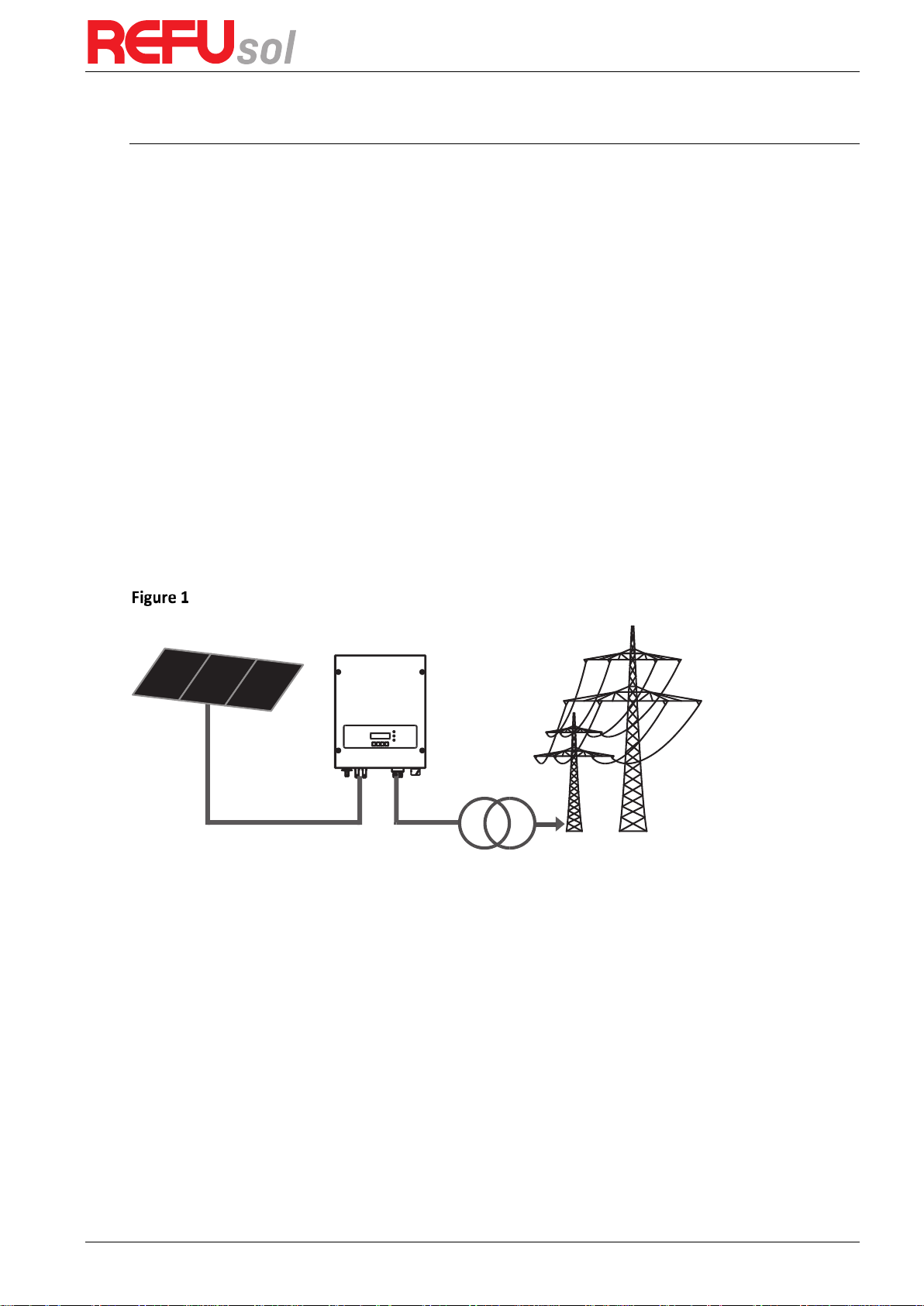
REFUone inverters are Dual MPPT grid-tied PV inverters which converts the DC power
generated by PV arrays into sine wave single-phase AC power and feeds it to the public
electrical grid, AC circuit breaker (refer to Section 4.4) and DC switch used as disconnect
device, and the disconnect device shall be easily accessible.
PV Grid-tied System
REFUone inverters can only be used with photovoltaic modules that do not require one of the
poles to be grounded. The operating current during normal operation must not exceed the
limits specified in the technical specifications. Only the photovoltaic modules can be connected
to the input of the inverter (do not connect batteries or other sources of power supply).
The choice of optional parts of inverter should be made by a qualified technician who knows
the installation conditions clearly.
Overall dimensions REFUone 3K-2T and 5K-2T (L×W×H): 437 mm×324 mm×130 mm.
Overall dimensions REFUone 7K-2T (L×W×H): 467 mm×352 mm×157 mm.

REFUone 3K-2T, 5K-2T, 7K-2T
10
352.0 mm
467.0 mm
157.0 mm
Front view and left view dimensions of REFUone 3K-2T and 5K-2T
Front view and left view dimensions of REFUone 7K-2T
324.0 mm
437.0 mm
130.0 mm
4
6
7
.
0
m
m

REFUone 3K-2T …7K-2T
11
Back view and Bracket dimensions REFUone 3K-2T and 5K-2T
Back view and Bracket dimensions REFUone 7K-2T
291.0 mm
110.0 mm
110.0 mm
130.5 mm
170.3 mm
160.0 mm
28.5 mm
9.0 mm
314.0 mm
258.7 mm
87.5 mm 87.5 mm
90.0 mm
265.0 mm
177.0 mm
85.0 mm
85.0 mm
86.0 mm
87.5 mm

REFUone 3K-2T, 5K-2T, 7K-2T
12
2.1.2
Labels on the equipment
The labels must NOT be hidden with
objects and extraneous parts (rags,
boxes, equipment, etc.); they must
be cleaned regularly and kept
visible at all times.
2.2
Function description
DC power generated by PV array is filtered through Input Board before entering into Power
Board. Input Board also offer functions such as insulation impedance detection and input DC
voltage / current detection. DC power is converted to AC power by Power Board. AC power is
filtered through Output Board then AC power is fed into the grid. Output Board also offer
functions such as grid voltage / output current detection, GFCI and output isolation relay.
Control Board provides the auxiliary power, controls the operation state of inverter and shows
the operation status by Display Board. Display Board displays fault code when inverter is in
abnormal operation conditions. At the same time, Control Board can trigger the relay so as to
protect the internal components.
Function module
1. Energy management unit
This control can be used to switch the inverter on/off through an external (remote) control.
2. Feeding reactive power into the grid
The inverter is able to produce reactive power and can therefore feed it into the grid through
the setting of the phase shift factor. Feed-in management can be controlled directly by the
grid company through a dedicated RS485 serial interface.
3. Limiting the active power fed into the grid
The inverter, if enabled can limit the amount of active power fed into the grid by the inverter
to the desired value (Expressed as a percentage).
4. Self power reduction when grid is over frequency
When the grid frequency is higher than the limited value, inverter will reduce output power
which is necessary for the grid stability.
5. Data transmission
The inverter or a group of inverters may be monitored remotely through an advanced
communication system based on RS-485 serial interface, or remotely via the WiFi.
6. Software update
SD card is used for updating the firmware.
Máx. tensão Entrada CC (Vmax)
Faixa de voltagem do MPPT
Máx. corrente entrada CC (Iop)
Máx. corrente de curto entrada CC (Icc)
Tensão CA nominal da rede
Corrente CA nominal de saída
Potência nominal de saída
Frequência nominal da rede
Fator de potência
Grau de proteção
Faixa de temperatura de operação
Classe de proteção
2x11 A
2x13.2 A
22.8 A
50 Hz
5000 W
90~580 V
220 V
IP65
Inversor Solar
Grid-Tied
Topologia do inversor
Não isolado
600 V
1 (ajustável +/-0.8)
-25°C a +65°C
Classe 1
Modelo: REFUone 5K-2T
fabricados na República Popular da China
REFU Elektronik GmbH, Marktstrasse 185
72793 Pfullingen, Alemanha
www.refu.com
Tipo: 801P005.200

REFUone 3K-2T …7K-2T
13
Electrical block diagram
Electrical block diagram
2.3
Efficiency curve
Efficiency Curve REFUone 3K-2T
82%
84%
86%
88%
90%
92%
94%
96%
98%
100%
5% 10% 20% 30% 40% 50% 60% 70% 80% 90% 100%
Efficiency [%]
% of Rated Output Power
Vpv=250V
Vpv=365V
Vpv=450V

REFUone 3K-2T, 5K-2T, 7K-2T
14
Efficiency Curve REFUone 5K-2T
Efficiency Curve REFUone 7K-2T
82%
84%
86%
88%
90%
92%
94%
96%
98%
100%
5% 10% 20% 30% 40% 50% 60% 70% 80% 90% 100%
Efficiency [%]
% of Rated Output Power
Vpv=300V
Vpv=365V
Vpv=450V
REFUone 3K-2T …7K-2T
15
Moving the
Inverter
3
Installation
Outlines of this chapter
This topic describes how to install the REFUone inverters.
Installation notes
Do NOT install the REFUone inverter on flammable material.
Do NOT install the REFUone inverter in an area used to store flammable or
explosive materials.
Danger
The enclosure and heat sink are very hot while the inverter is working, therefore
do NOT install the REFUone inverter in places where you might touch them
inadvertently.
Caution
Consider the weight of the inverter when transporting and moving.
Choose an appropriate mounting position and surface.
Assign at least two persons to install the inverter.
Attention
3.1
Installation Process
Installation flowchart
3.2
Checking Before Installation
3.2.1
Checking Outer Packing Materials
Packing materials and components may be damaged during transportation. Therefore, check
the outer packing materials before installing the inverter. Check the outer packing materials
for damage, such as holes and cracks. If any damage is found, do not unpack the REFUone
inverter and contact the dealer as soon as possible. You are advised to remove the packing
materials within 24 hours before installing the REFUone inverter.
3.2.2
Checking Deliverables
After unpacking the inverter, check whether deliverables are intact and complete. If any
damage is found or any component is missing, contact the dealer.
End
Install the
Inverter
Install the rear panel
Check before
installation
Prepare installation
tools
Determine the
installation position
REFUone 3K-2T, 5K-2T, 7K-2T
16
Table 1 shows the components and mechanical parts that should be delivered
No. Pictures
Description
Quantity
REFUone 3K2T, 5K-2T
Quantity
REFUone 7K-2T
1
REFUone inverter
1 pcs
1 pcs
2
Rear panel
1 pcs
1 pcs
3
PV+ input terminal
2 pcs
3 pcs
4
PV-input terminal
2 pcs
3 pcs
5
Metal terminals secured
to PV+ input power cables
2 pcs
3 pcs
6
Metal terminals secured
to PV- input power cables
2 pcs
3 pcs
7
M5 Hexagon screws
3 pcs
3 pcs
8
M6 flat washer
7 pcs
10 pcs
9
Expansion bolts
7 pcs
10 pcs
10
Self-tapping screw
5 pcs
8 pcs
11
Manual
(English and Portugese)
1 pcs
1 pcs
12 AC output terminal
1 pcs
-
REFUone 3K-2T …7K-2T
17
13 485 terminal (2pin)
1 pcs
-
14 AC connection housing
-
1 pcs
3.3
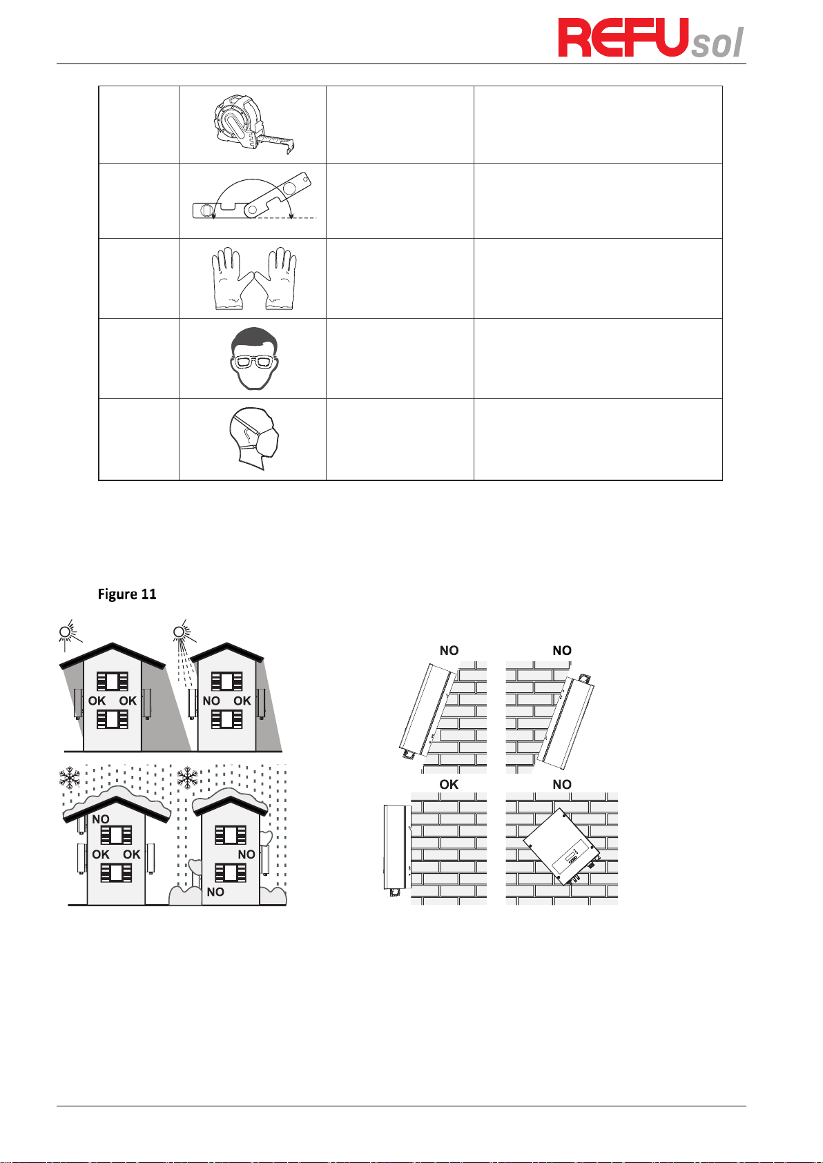
Tools
Prepare tools required for installation and electrical connections.
Table 2 shows the tools required for installation and electrical connections.
No.
Tool
Model
Function
1
Hammer drill
Recommend drill dia.
6mm
Used to drill holes on the wall
2
Screwdriver
wiring
3
Removal tool
Remove PV terminal
4
Wire stripper
Strip wire
5
4mm Allen Wrench
Turn the screw to connect rear panel
with inverter
6
Crimping tools
Used to crimp power cables
7
Multi-meter
Used to check grounding
8
Marker
Used to mark signs
A1
4.0
REFUone 3K-2T, 5K-2T, 7K-2T
18
9
Measuring tape
Used to measure distances
10
Level
Used to ensure that the rear panel is
properly installed
11
ESD gloves
Operators wear
12
Safety goggles
Operators wear
13
Anti-dust respirator
Operators wear
3.4
Determining the Installation Position
Determine an appropriate position for installing the REFUone inverter. Comply with the
following requirements when determining the installation position:
Installation Requirements
0-180º

REFUone 3K-2T …7K-2T
19
clearance for single REFUone inverter
Installation of multiple REFUone inverters
REFUone 3K-2T, 5K-2T, 7K-2T
20
3.5
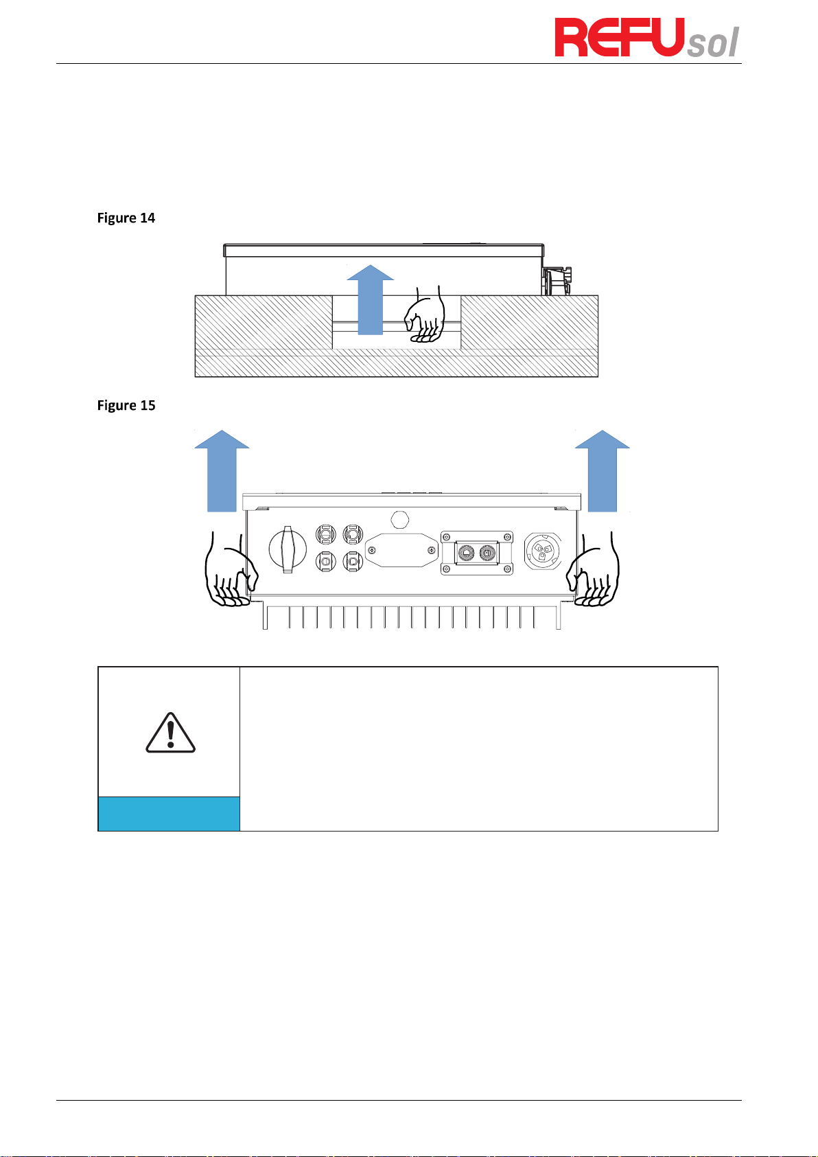
Moving the REFUone inverter
This topic describes how to move the REFUone horizontally to the installation position
Step 1
Open the packaging, insert hands into the slots on both sides of the inverter and hold
the handles, as shown in Figure 14and Figure 15.
Moving the inverter (1)
Moving the REFUone inverter (2)
Step 2
Lift the REFUone from the packing case and move it to the installation position.
To prevent device damage and personal injury, keep balance when moving the
inverter because the inverter is heavy.
Do not put the inverter with its wiring terminals contacting the floor because
the power ports and signal ports are not designed to support the weight of the
inverter. Place the inverter horizontally.
When placing the inverter on the floor, put foam or paper under the inverter to
protect its shell
Attention
3.6
Installing REFUone inverter
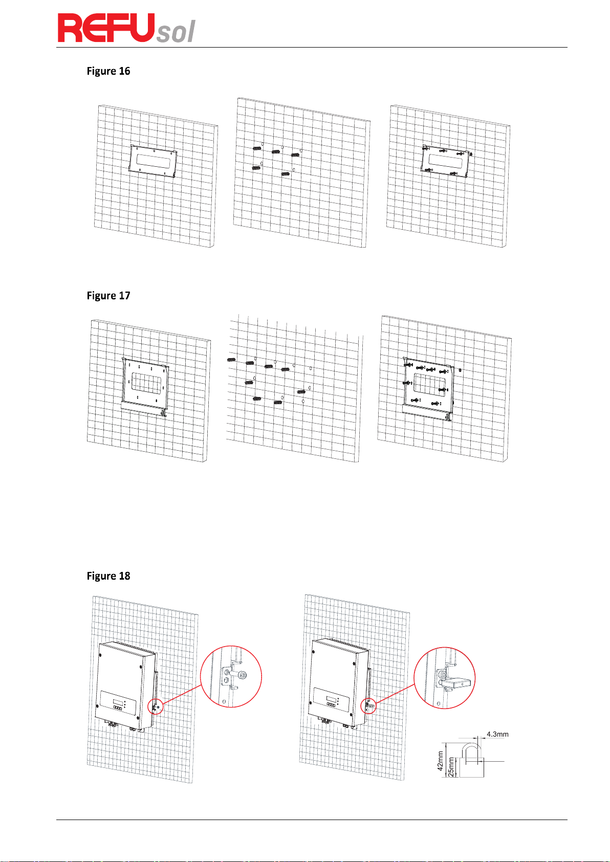
Step 1
Determine the positions for drilling holes, ensure the hole positions are level, then mark
the hole positions using a marker pen, use the hammer drill to drill holes on the wall. Keep the
hammer drill perpendicular to the wall, do not shake when drilling, so as not to damage the
wall. If the error of the hole positions is too big, you need to reposition.
Step 2
Insert the expansion bolt vertically into the hole, pay attention to the insertion depth
of the expanding bolt (should be deep enough).
Step 3
Align the rear panel with hole positions, fix the rear panel on the wall by tightening the
expansion bolt with the nuts.
REFUone 3K-2T …7K-2T
21
Wall mounting 3K-2T, 5K-2T
Step 1 Step 2 Step 3
Wall mounting 7K-2T
Step 1 Step 2 Step 3
Step 4
Hook the inverter to the rear panel. Using an M5 screw to secure the inverter to the
rear panel to ensure safety.
Step 5
You can secure the inverter to the rear panel and protect it from stealing by installing
an anti-theft lock (this action is optional).
Securing the REFUone inverter
Step 4 Step 5

REFUone 3K-2T, 5K-2T, 7K-2T
22
Connect AC Output power
Cables
4
Electrical Connections
Outlines of this chapter
This topic describes the REFUone inverter electrical connections. Read this part carefully
before connecting cables.
NOTE:
Before performing electrical connections, ensure that the DC switch is OFF. Since the stored
electrical charge remains in a capacitor after the DC switch is turned OFF. So it’s necessary to
wait for at least 5 minutes for the capacitor to be electrically discharged.
Installation and maintenance of inverter, must be operated by professional
electrical engineer.
Attention
PV modules generate electric energy when exposed to sunlight and can create an
electrical shock hazard. Therefore, before connecting DC input power cable, cover
PV modules using opaque cloth.
Danger
In Germany, the PV array maximum voltage must be ≤ 600V, max output of
single inverter is 4.6KVA and max output of PV system is 13.8KVA.
The REFUone inverter has 2 MPP trackers, all PV modules connected to the
same MPPT should have similar rated electrical characteristics (including Isc,
Voc, Im, Vm, Pm and temperature coefficients), have the same number of
series connected PV modules and be all in the same orientation (azimuth and
tilt angle).
Note
4.1
Electrical connection
Shows the flowchart for connecting cables to the inverter
4.2
Connecting PGND Cables
Connect the inverter to the grounding electrode using protection ground (PGND) cables for
grounding purposes.
The inverter is transformer-less, requires the positive pole and negative pole of
the PV array are NOT grounded. Otherwise it will cause inverter failure. In the PV
power system, all non current carrying metal parts (such as: PV module frame, PV
rack, combiner box enclosure, inverter enclosure) should be connected to earth.
Attention
End
Connect Communication
Cables (not mandatory)
Start
Connect PGND Cables
Connect DC Input power
Cables

REFUone 3K-2T …7K-2T
23
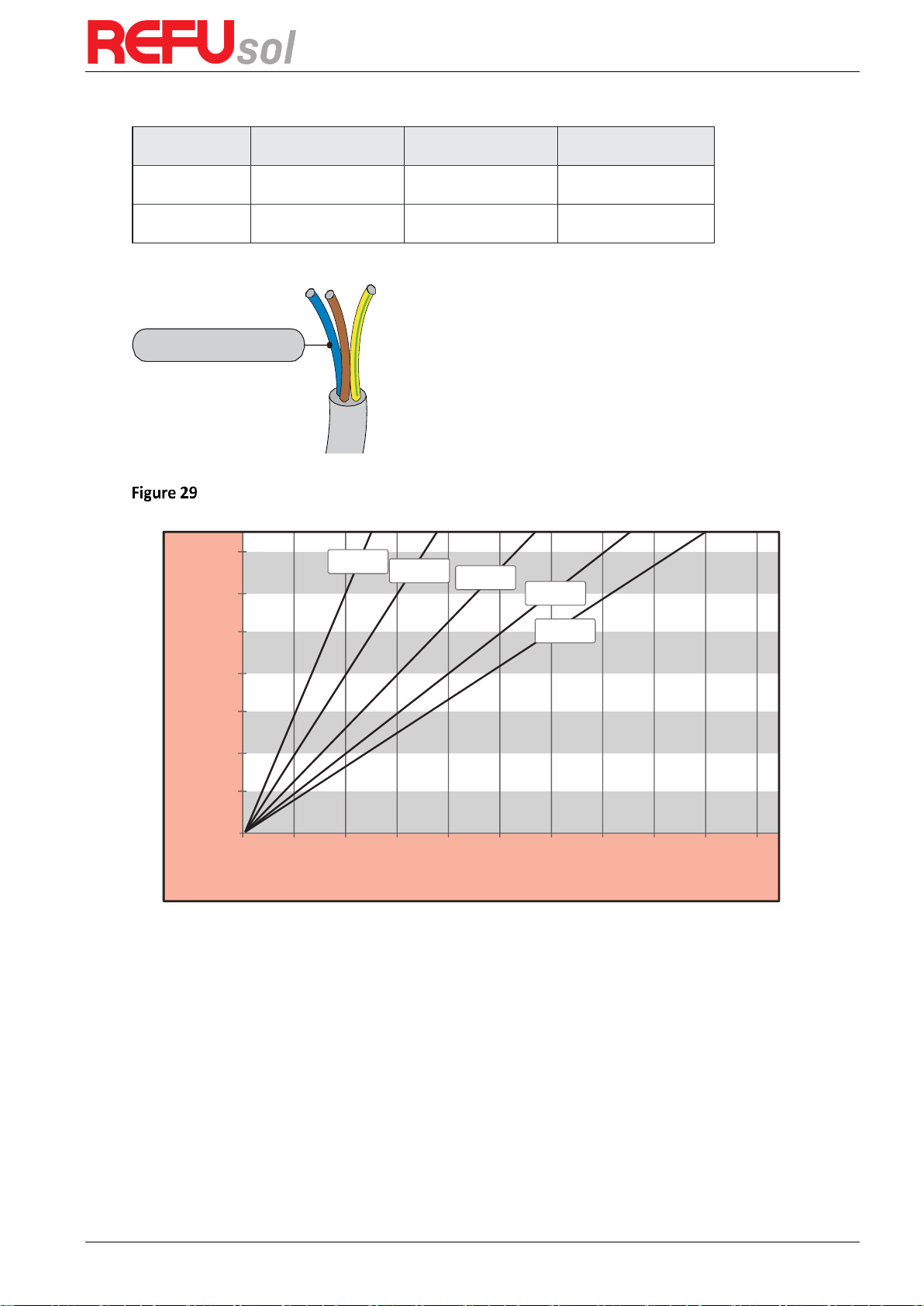
Prerequisites:
The PGND cables are prepared (≥6mm² outdoor power cables are recommended for grounding
purposes), the color of cable should be yellow-green.
Procedure:
Step 1
Remove the insulation layer with an appropriate length using a wire stripper, as shown
in Figure 20.
Preparing a ground cable (1)
Step 2
Insert the exposed core wires into the OT terminal and crimp them by using a crimping
tool, as shown in Figure 21.
Preparing a ground cable (2)
Note 1:
L3 is the length between the insulation layer of the ground cable and the crimped
part.L4 is the distance between the crimped part and core wires protruding from the
crimped part.
Note 2:
The cavity formed after crimping the conductor crimp strip shall wrap the core wires
completely. The core wires shall contact the terminal closely.
Step 3
Install the crimped OT terminal, flat washer using M5 screw, and tighten the screw to a
torque of 3 Nm using an Allen wrench.
Ground terminal composition
L2=L1+(2-3)mm
L1
L3<2mm
L4<1.5mm
1. M5 screw
2. Flat washer
3. OT Terminal

REFUone 3K-2T, 5K-2T, 7K-2T
24
4.3
Connecting DC Input Power Cables
The REFUone 3K-2T … 7K-2T has 2 MPP Trackers. The MPPT 1 and MPPT 2
input is marked with PV1 and PV2 respectively at the connectors.
The maximum power for each MPPT is limited (see chapter 8.1 DC Data)!
If you want to use the full power of the inverter, both inputs need to be
connected.
If you want to use one string of solar panels only, you need to connect it to
both inputs PV1 and PV2 in parallel, and set the inverter input mode to
“parallel mode” (see chapter 6.3 Main Interface at (A) 9. Set Input mode).
Attention
Correct string connections with 1 String on 3K/5K-2T, and 2 Strings on 7K-2T
Table 3 Recommended DC input cable specifications
Cross-Sectional Area (mm2)
External Cable Diameter (mm)
Range
Recommended Value
4.0 … 6.0
4.0
4.5 … 7.8
Procedure
Step 1
Remove cable glands from the positive and negative connectors.
Step 2
Remove the insulation layer with an appropriate length from the positive and negative
power cables by using a wire stripper as show in Figure 24.
REFUone 3K/5K-2T
1 String - correct
1 to 2 Adapter
PV 1
PV 2
MPPT 2
MPPT 1
...
REFUone 7K-2T
2 Strings - correct
PV 1
PV 1
PV 2
MPPT 1
MPPT 2
...
...

REFUone 3K-2T …7K-2T
25
Connecting DC input power cables
Step 3
Insert the positive and negative power cables into corresponding cable glands.
Step 4
Insert the stripped positive and negative power cables into the positive and negative
metal terminals respectively and crimp them using a clamping tool. Ensure that the cables are
crimped until they cannot be pulled out by force less than 400 N, as shown in Figure 25:
Connecting DC input power cables
1.
Positive power cable
2.
Negative power cable
Step 5
Insert crimped power cables into corresponding housings until you hear a "click" sound.
The power cables snap into place.
Step 6
Reinstall cable glands on positive and negative connectors and rotate them against the
insulation covers.
Step 7
Insert the positive and negative connectors into corresponding DC input terminals of
the inverter until you hear a "click" sound, as shown in Figure 26:
Connecting DC input power cables
1. Bayonet
Note: Insert the stoppers into the unused DC connectors.
1. Positive power cable
2. Negative power cable
Note
L2 is 2 to 3 mm longer than L1.

REFUone 3K-2T, 5K-2T, 7K-2T
26
Follow-up Procedure
To remove the positive and negative connectors from the inverter, insert a removal wrench
into the bayonet and press the wrench with an appropriate strength, as shown in Figure 27
Before removing the positive and negative connectors, ensure that the DC SWITCH
is OFF.
Caution
Removing a DC input connector
4.4
Connecting AC Output Power Cables
Connect the REFUone to the AC power distribution frame (PDF) or power grid using AC output
power cables.
It is not allowed for several inverters to use the same circuit breaker
It is not allowed to connect loads between inverter and circuit breaker
AC breaker used as disconnect device, and the disconnect device shall remain
readily operable.
In Italy, any solar system bigger than 6kW should be connected to grid via an
external SPI.
Caution
Context
All the AC output cables used for the inverters are outdoor three-core cables. To facilitate the
installation, use flexible cables. Table 4-2 lists the recommended specifications for the cables.
NOT allowed: connect loads between inverter and circuit breaker
TV
REFUone 3K-2T …7K-2T
27
Table 4 Recommended AC output cable specifications
Model
REFUone 3K-2T
REFUone 5K-2T
REFUone 7K-2T
Cable (Copper)
≥ 4mm²
≥ 6mm²
≥ 6mm²
Circuit Breaker
20A/230V/2P/0.1A
32A/230V/2P/0.1A
40A/230V/2P/0.1A
Multi core copper wire
AC cable should be correctly sized to ensure the power loss
in AC cable is less than 1% of the rated power. If the
resistance of the AC cable is too high, it will cause a huge
increase in the AC voltage, which may lead to a
disconnection of the inverter from the electrical grid. The
relationship between power loss in AC cable and wire
length, wire cross sectional area is shown in the following
figure:
wire length, wire cross sectional area and wire power loss:
REFUone 3K-2T, 5K-2T AC wire connections procedure:
Step 1
Select appropriate cables according to Table 4-2, Remove the insulation layer of the AC
output cable using a wire stripper according to the figure shown below:
0m 10m 20m 30m 40m 50m 60m 70m 80m 90m 100m
1.4%
1.2%
1.0%
0.8%
0.6%
0.4%
0.2%
0.0%
Loss
Length
2.5mm²
4.0mm²
6.0mm²
8.0mm²
10.0mm²
Multi core copper wire

REFUone 3K-2T, 5K-2T, 7K-2T
28
A: 30 … 50mm B: 6 … 8mm;
Step 2
Disassemble the AC connector according to the figure shown below: insert the AC
output cable (with its insulation layer stripped according to step 1) through the waterproof
locking cable gland;
Step 3
Connect AC output cable as per the following requirements:
Connect the yellow-green wire to the hole labeled ‘PE’, fasten the wire using an Allen wrench;
Connect the brown wire to the hole labeled ‘L’, fasten the wire using an Allen wrench;
Connect the blue wire to the hole labeled ‘N’, fasten the wire using an Allen wrench;
L--brown, N--blue, PE--yellow/green
Step 4
Secure the locking cable gland clockwise, shown as below: make sure that all the wires
are securely connected;
Step 5
Connect the AC output connector to the output wiring terminal of inverter, rotate the
AC connector clockwise until the fastener reaches its designated position, as shown below:
A
B

REFUone 3K-2T …7K-2T
29
Step 4 Step 5
REFUone 7K-2T: AC wire connections procedure:
Step 1:
As shown in Figure 34to make the output line, the wire ends need to use tube-type
terminals. It is recommended to use tube-type terminals KST model: E6012 (10 AWG)
A1: recommendation: Tube type terminal KST model: E6012 (10AWG)
Step 2:
As shown in Figure 35, remove the waterproof cover with the cross screwdriver.
Step 3:
As shown in Figure 36, remove the waterproof plug, put the finished output cable
through the waterproof lock nut, Connect AC output cable as per the following requirements:
A1

REFUone 3K-2T, 5K-2T, 7K-2T
30
A2: waterproof plug
Connect the yellow and green cable to the lock hole of AC terminal marked with
identification;
Connect the red line to the lock hole of the terminal with L identification AC; connect the
black line to the lock hole of the terminal with N identification AC;
Step 4:
as shown in Figure 37, tighten
the
waterproof lock nut, cover and tighten it.
install the waterproof
4.5
Connecting Communications Cables
The wiring methods are the same for RS485, DRM0 and CT, this part describes their wiring
methods all together:
Table 5 Recommended communication cable sizes are shown below
Communication function
RS485
DRM0
(External Contact)
CT
(Current Transformer)
Cable size
0.5 … 1.5 mm²
0.5 ... 1.5 mm²
0.5 … 1.5 mm²
Outside diameter
2.5 … 6 mm
2.5 … 6 mm
2.5 … 6 mm
Step 1:
Remove the communication waterproof cover using a screwdriver;
L
N
A2

REFUone 3K-2T …7K-2T
31
A1
Cable Gland
REFUone 3K-2T, 5K-2T REFUone 7K-2T
Step 2:
Unlock the waterproof cable gland, remove the stopper in the waterproof connector
Cable Gland
REFUone 3K-2T, 5K-2T REFUone 7K-2T
Note: The waterproof connectors correspond to: I/O, dry contact, RS485 from left to
right. Unlock the waterproof connectors according to the communication functions you
are using. Do NOT unlock the unused connectors.
Step 3:
Select appropriate cable according to Table 5, remove the insulation layer using a wire
stripper, the length of the wire core is about 6 mm, insert the cable through the cable gland
and waterproof cover, as shown in the figure below:
A1: Waterproof stopper
REFUone 3K-2T, 5K-2T, 7K-2T
32
cut
6 mm
REFUone 3K-2T, 5K-2T REFUone 7K-2T
Step 4:
Choose the terminal according to Table 6, connect the wires as per the labels, and
secure the wires using a slotted screwdriver.
Note: keep the unused terminals for future use.
Table 6 functional description of the communication terminals
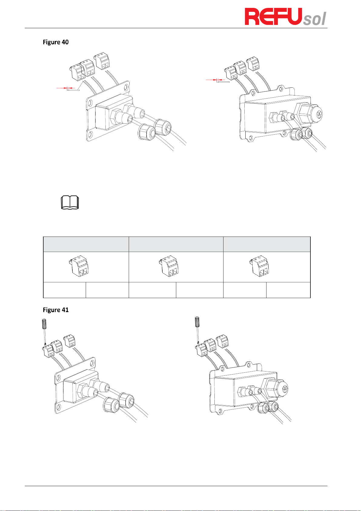
RS485
DRM0
CT
(2 pin)
(2 pin)
(2 pin)
TX-
TX+
DRM0
GND
CT-
CT+
REFUone 3K-2T, 5K-2T REFUone 7K-2T
Step 5:
Insert the terminal as per the printed label, and then tighten the screws to fix the
waterproof cover, rotate the cable gland clockwise to fasten it securely.
6 mm
cut
REFUone 3K-2T …7K-2T
33
cut
Connected in parallel
6 mm
REFUone 3K-2T, REFUone 5K-2T REFUone 7K-2T
If users need to connect multiple inverters via RS485 wires, refer to the figure shown below:
RS485 wires are connected in parallel, so 4 wires may be required. First connect the two 485+
(TX+) wires in parallel, then connect the two 485- (TX-) wires in parallel, then insert them into
the terminal and tighten the screws using a slotted screwdriver.
Note: We recommend using two different colors of wires to connect TX- (485-) and TX+ (485+).
Wires of the same color are connected together to avoid wrong wire connections.
REFUone 3K-2T, 5K-2T REFUone 7K-2T
REFUone 3K-2T, 5K-2T, 7K-2T
34
4.6
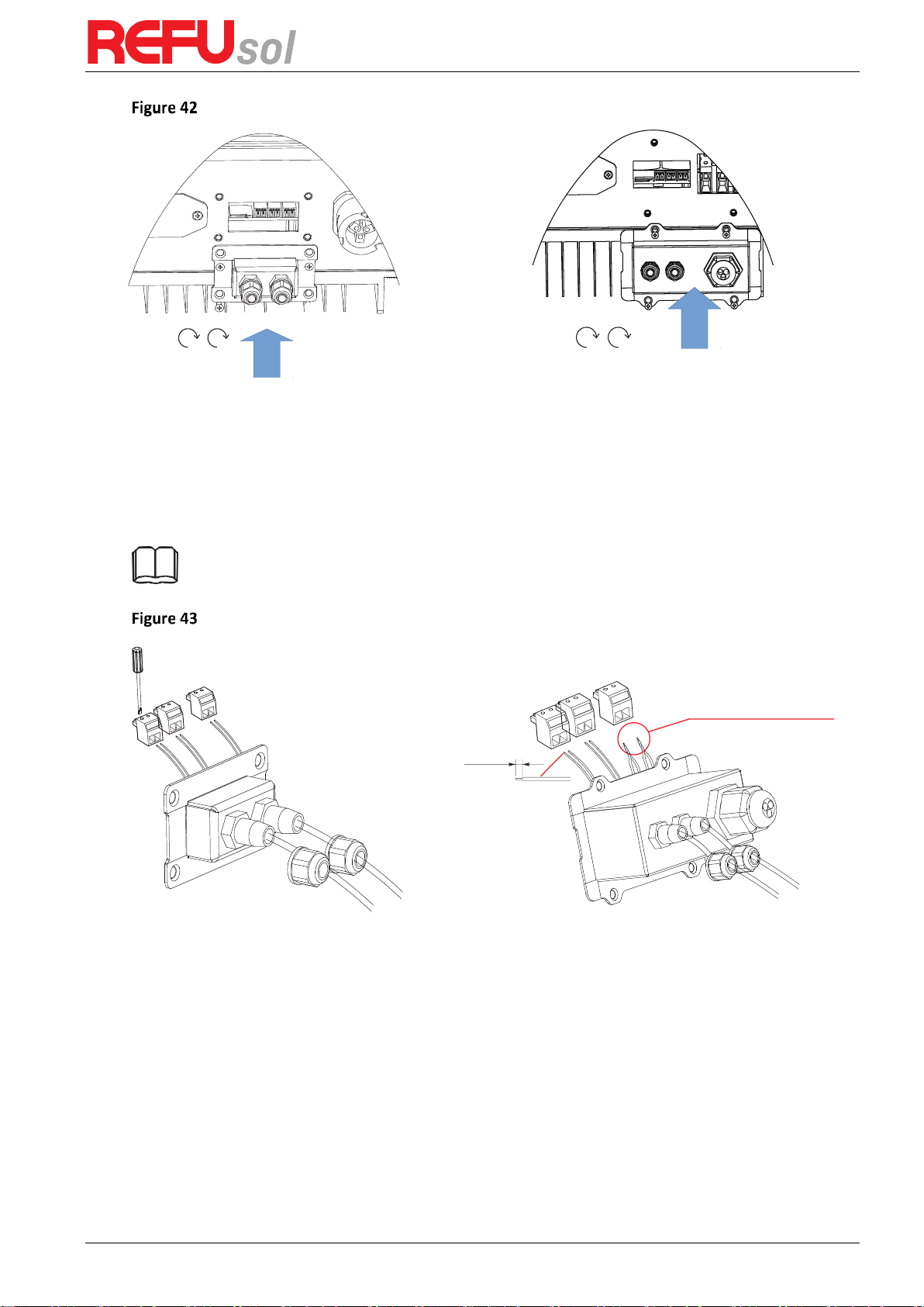
WiFi/GPRS module installation procedure
Step 1
: remove WiFi/GPRS waterproof cover using screw driver
Step 2
: Assemble logger to the inverter communication interface as shown in the diagram.
Step 3
: fasten WiFi/GPRS module using screws.
REFUone 3K-2T …7K-2T
35
4.7
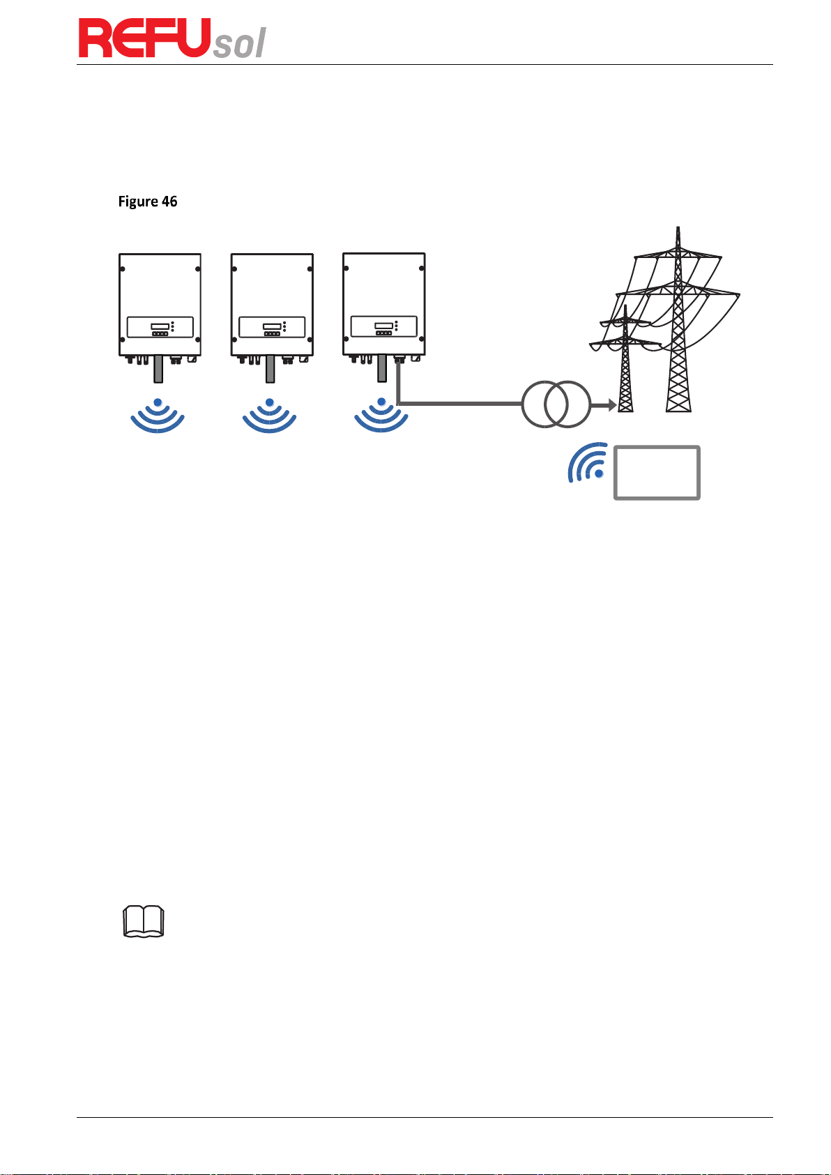
WiFi Communication
The REFUone grid-connected inverters offer Wi-Fi communication modes as standard.
Refer to the figure shown below:
The operation information (generated energy, alert, operation status) of the inverter can be
transferred to the REFUlog monitoring portal via WiFi.
4.7.1
Configuration of WiFi Stick with PC
Preparation:
The WiFi Stick is installed according to section 4.6 and the REFUone Inverter must
be running.
Follow the following steps to configure the WiFi stick:
Step 1
: connect your PC with WiFi network to the Access Point of the WiFi stick. The name of
the WiFi is “AP” followed by the serial number of the WiFi Stick (see type label)
If you are asked for a password, read it from the WiFi Stick label at PWD
Step 2
: Open an internet browser, and enter the address
10.10.100.254
Recommended browsers: Internet Explorer 8+, Google Chrome 15+, Firefox 10+
Step 3
: Fill in username and password, both of which are “admin” as default. The Status page
opens
Step 4
: Click “Wizard” to configure how the WiFi Stick can access your internet gateway.
Result: the WiFi Stick will start to send monitoring data to REFUlog.
Note: Please refer to the detailed instructions delivered with the WiFi stick.
Internet
Gateway

REFUone 3K-2T, 5K-2T, 7K-2T
36
4.7.2
Configuration of WiFi Stick with App
To download the App for iPhone, search "REFUone Set" in Apple Store.
To download the App for Android, search "REFUone Set" in Google Play Store.
WiFi Connection Configuration
1) The App will automatically get your WiFi network, so you need to enter your WiFi password
to continue the configuration. If the network is not correct, select [switch network], then
find or manually enter the network ID.
2) On iPhone, go to [Network Settings] interface, and select the stick logger's network with
the name AP _XXXXX (Serial Number of the WiFi Stick without leading 0). Then return to
the App, the WiFi Stick will start to configure.
3) The connection will automatically start after connect the network.
Note: If it is unable to find an AP_XXXXX (Serial number without leading 0) in
wireless network list, please make sure to shorten the distance between WiFi
routers and Stick to under 10 meters. The connection or setting may appear
problem, if you have repeat the above steps and still cannot find the AP _XXXXX.
Please follow the WiFi Stick Manual for troubleshooting or contact our Customer
Center.
4.8
Monitoring Portal REFUlog
The REFUone inverter are sending the operating data to the REFUlog monitoring portal, when
the WiFi connection is established.
Once an internet connection is established, the inverter will automatically start to send data
to REFUlog every 5 minutes.
To view the inverter data, open
www.refu-log.com
with your browser and login with your
existing username and password or register as a new user.
You can use the activation code provided on the inverter to assign one or more inverter to a
PV system in your account.
REFUlog Monitoring Portal

REFUone 3K-2T …7K-2T
37
4.9
RS485 Communication
4.9.1
Communication between one inverter and one PC with RS485
Refer to the figure shown below, connect the TX+ and TX- of the inverter to the TX+ and TX- of
the RS485 to USB adapter, and connect the USB port of the adapter to the computer. (Note 1)
1: Radio ripple control receiver 2: RS485 to USB Adapter
4.9.2
Communication between multiple inverters and one PC with RS485
Refer to the following figure: RS485 wires are connected in parallel between inverters, refer to
section 4.5 of this manual for wire connection methods. Connect the TX+ and TX- of the
inverter to the TX+ and TX- of the RS485→USB adapter; connect the USB port of the adapter
to the computer. A maximum of 31 inverters can be connected in one daisy chain. (Note 2)
1: Radio ripple control receiver 2: RS485 to USB Adapter
Note 1:
The length of the RS485 communication cable should be less than 1000 m.
Note 2:
When multiple inverters are connected via RS485 wires, set mod-bus
address to differentiate the inverters.
1
2
PC
1
2
PC

REFUone 3K-2T, 5K-2T, 7K-2T
38
5
Commissioning of inverter
5.1
Safety inspection before commissioning
5.2
Start Inverter
Step 1:
Turn ON the DC switch.
Step 2:
Turn ON the AC circuit breaker.
When the DC power generated by the solar array is adequate, the REFUone inverter will start
automatically. Screen showing „normal” indicates correct operation.
Step 3:
Choose the correct country code. (Refer to section 6.3 of this manual)
Notice: Different distribution network operators in different countries have different
requirements regarding grid connections of PV grid connected inverters.
Therefore, it is very important to make sure that you have selected the correct country code
according to requirements of local authority.
Please consult qualified electrical engineer or personnel from electrical safety authorities
about this.
REFU Elektronik GmbH is not responsible for any consequences arising out of incorrect country
code selection.
If the inverter indicates any fault, please refer to of this manual trouble shooting for help.
Ensure that DC and AC voltages are within the acceptable range of the inverter.
Attention
REFUone 3K-2T …7K-2T
39
6
Operation interface
Outlines of this chapter
This section introduces the display, operation, buttons and LED indicator lights of REFUone
Inverter.
6.1
Operation and Display Panel
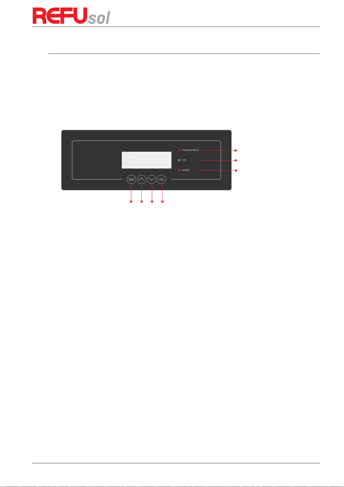
Buttons and Indicator lights
Ground Fault Warning Light
Inverter Status Light
Warning Light
Key buttons
(A) Key buttons
Back
: to return to previous menu or enter into main menu from the standard interface.
Up
: to move up or increase value
Down
: to move down or decrease value
OK
: to confirm selection
(B) Indicator Lights
Inverter States Light(GREEN)
o Flashing: ‘Wait’ or ‘Check’ state
o ON: ‘Normal’ state
o OFF: ‘Fault’ or ‘Permanent’ state
Warning Light (RED)
o ON: ‘Fault’ or ‘Permanent’ state
o OFF: ‘Normal’ state
GFCI Warning Light (RED)
o ON: ‘ID12: GFCIFault’ or ‘ID20: GFCIDeviceFault’
o OFF: GFCI normal
REFUone 3K-2T, 5K-2T, 7K-2T
40
6.2
Standard Interface
When power-on, LCD interface displays INITIALIZING, refer below picture.
When control board successfully connected with communication board, the LCD display the
current state of the inverter, display as shown in the figure below.
Waiting States, Countdown 10S
(depends country code, some are 60s)
Checking
Normal Power Generation
Initializing…
Wait 10s
Check
Normal
REFUone 3K-2T …7K-2T
41
Regular error state
Unrecoverable error state
(C) Inverter states includes: wait, check, normal, fault and permanent
Wait:
Inverter is waiting to Check State at the end of reconnection time. In this state,
grid voltage value is between the max and min limits and so on; If not, Inverter
will go to Fault State or Permanent State.
Check:
Inverter is checking isolation resistor, relays, and other safety requirements. It
also does self-test to ensure inverter software and hardware are functional.
Inverter will go to Fault State or Permanent State if any error or fault occurs.
Normal:
Inverter enter to Normal State, it is feeding power to the grid; inverter will go
to Fault State or Permanent state if any error or fault occurs.
Fault:
Fault State: Inverter has encountered recoverable error. It should recover if the
errors disappear. If Fault State continues, please check the inverter according
error code.
Permanent:
Inverter has encountered unrecoverable error, we need maintainer debug this
kind of error according to error code.
When the control board and communication board connection fails, the LCD display interface
as shown in the figure below.
6.3
Main Interface
Press „ESC” button under standard interface to enter into main interface, including:
Normal
1. Enter Setting
2. Event List
3. SystemInfo
4. System Time
5. Software Update
Fault
Permanent
DSP communicate fail

REFUone 3K-2T, 5K-2T, 7K-2T
42
(A) “Enter Setting” Interface as below:
1.Enter Setting
1. Set Time
11. Set Start Parameter
2. Clear Energy
12. Set Safety Voltage
3. Clear Events
13. Set Safety Frequency
4. Set Country
14. Insulation Resistance
5. On-Off Control
15. Set Reactive Power
6. Enable Set Country
16. Set Power Derate
7. Set Energy
17. Reflux Power
8. Set Address
18. MPPT Scan
9. Set Input mode
19. DRM0 Control
10. Set Language
1. Set Time
Users press „ESC” button to enter „Enter Setting” interface, Press „OK” button to enter main
setting interface. Enter „ Set Time” by pressing „Up” button or „Down” button, then press ”OK“
button and start to set up time.
Time set from year, month, day, minutes, and seconds in turns, „Up” button or „Down” button
to choose different value to set each date. Set each value is need to press „OK” button to
confirm setting. „success” is displayed if the setting time is correct, „fail” means failure
settings.
2. Clear Energy
Users press „ESC” button to enter „Enter Setting” interface, Press OK button to enter main
setting interface. Then Enter „Clear Energy” by pressing „Up” button or „Down” button, press
„OK” to enter password 001 by pressing „Up” and „Down” button and then press „Enter” to
start to clear produce. „success” is displayed after settings.
3. Clear Events
Users press „ESC” button to enter „Enter Setting” interface, Press „OK” button to enter main
setting interface. Enter „Clear Events” by pressing „Up” button or „Down” button. Press „OK”
button and start to clear events. „success” is displayed after settings.
4. Set Country
Users press „ESC” button to enter „Enter setting” interface, Press OK button to enter main
setting interface. Enter „Set Country Code” by pressing „Up” button or „Down” button, press
„OK” button. If it shows “set disable” on the screen, then you can NOT choose the operating
country, you should enable country setting through "Enable Set Country" interface. If it shows
"set Country code?" on the screen, then press “OK” button to start country setting. "Success"
will be shown on the screen after a successful country setting.

REFUone 3K-2T …7K-2T
43
Table 7 Country code setting
Code
Country
Code
Country
Code
Country
00 Germany VDE AR-N4105
12 Poland
24 Cyprus
01 CEI0-21 Internal
13 Germany BDEW
25 India
02
Australia
14 Germany VDE 0126
26 Philippines
03 Spain RD1699
15 Italy CEI0-16
27 NewZealand
04 Turkey
16 UK-G83
28 Brazil
05 Denmark
17 Greece island
29 Slovakia VSD
06 Greece Continent
18 EU EN50438
30 Slovakia SSE
07 Netherland
19 IEC EN61727
31 Slovakia ZSD
08 Belgium
20 Korea
32
CEI0-21 In Areti
09 UK-G59t
21 Sweden
10 China
22
Europe General
11 France
23 CEI0-21 External
5. Remote Control
Users press „ESC” button to enter „Enter setting” interface, Press OK button to enter main
setting interface. Enter „Remote Control” by pressing „Up” button or „Down” button. Press „OK”
button and enter Remote Control Switch on and off interface. Choose „Enable” or „Disable”
by pressing „Up” button or „Down” button, press „OK” button, then communication board
start to transmit control signals to control board. „Success” is displayed after setting success;
otherwise it will show „fail”.
6. Enable Set Country
Users press Back button to enter „Enter setting” interface, Press OK button to enter main
setting interface. Enter „Enable Set Country” by pressing „Up” button or „Down” button, press
„OK” button and enter „Input Password” Setting interface. Press „ESC” button to set
passwords (default: 0001), increase or decrease value though pressing „Up” button or „Down”
button, press „OK” button to next value setting. „Error!” Try again” will be displayed for wrong
passwords. Press „ESC” button and rekey in the correct passwords. „ Success” will be displayed
if setting successfully.
Attention: when inverter working for power generation over 24h, country setting is forbidden,
it can only be set after LCD setting. Key in passwords for country setting through LCD (default:
0001), country setting can be set in 24h after keying in the correct passwords, over 24h, set
through LCD again.
7. Set Energy
Users press Back button to enter „Enter setting” interface, Press OK button to enter main
setting interface. Enter „Set Total Energy” by pressing „Up” button or „Down” button , then press
„OK” button and enter „Input Password” Setting interface. Press „OK” button to set passwords
(default: 0001), increase or decrease value though pressing „Up” button or „Down” button,

REFUone 3K-2T, 5K-2T, 7K-2T
44
press „OK” button to confirm the value and to next value setting. „Error! Try again” will be
displayed for wrong passwords. Press „ESC” button and rekey in the correct passwords then
set total energy. „Success” or „fail” is displayed after setting.
8. Set address
Users press „ESC” button to enter „Enter setting” interface, press ”OK“ button to enter main
setting interface. Enter „ Set address” by pressing „Up” button or ”Down“ button. Press „OK”
button and enter setting interface. Choose corresponding setting items by pressing „Up”
button or „Down” button, then press „OK” button. „Success” or „fail” is displayed after setting.
9. Set Input mode
Input mode selection: the inverter has 2 MPPT channels, the 2 MPPT can operate independently, also can operate in parallel. If the PV strings are connected in parallel outside the
inverter, you should choose the "in parallel mode", otherwise use the default setting. Press
„ESC” button to enter „Enter setting” interface, press ”OK“ button to enter main setting
interface. Enter „Set inputmode” by pressing „Up” or ”Down“ buttons. Press „OK” button to
enter setting interface. Choose „In parallel Mode?” or „Independent Mode?” by pressing „Up”
or „Down” buttons, then press „OK” button. „Success” or „fail” is displayed after setting.
10. Set Language
Users press „ESC” button to enter „Enter setting” interface, Press ”OK“ button to enter main
setting interface. Enter „Set Language” by pressing „Up” button or ”Down“ button. Press „OK”
button and enter setting interface. Choose corresponded setting items by pressing „Up” button
or „Down” button, then press „OK” button. „Success” or „fail” is displayed after setting.
11. Start Parameter
User can change the start parameter by the LCD. First the User need to copy the TXT file which
is used to change the start parameter to the SD card.
Users press Back button to enter „Enter setting” interface, Press OK button to enter main
setting interface. Enter „Set StartPara” by pressing „Up” button Or „Down” button, press „OK”
button and enter „Input Password” Setting interface. Press „ESC” button to set passwords
(default: 0001), increase or decrease value though pressing „Up” button or „Down” button,
press „OK” button to next value setting. „Error!” Try again” will be displayed for wrong
passwords. Press „ESC” button and rekey in the correct passwords. „ Success” will be displayed
if setting successfully.
12. Safety Voltage
User can change the Voltage protection point by the LCD. First the User need to copy the TXT
file which is used to change the Voltage protection point to the SD card.
Users press Back button to enter „Enter setting” interface, Press OK button to enter main
setting interface. Enter „Set SafetyVolt” by pressing „Up” button Or „Down” button, press
„OK” button and enter „Input Password” Setting interface. Press „ESC” button to set
passwords (default: 0001), increase or decrease value though pressing „Up” button or „Down”
button, press „OK” button to next value setting. „Error!” Try again” will be displayed for wrong
passwords. Press „ESC” button and rekey in the correct passwords. „Success” will be displayed
if setting successfully.
13. Safety Frequency
User can change the Frequency protection point by the LCD. First the User need to copy the.
TXT file which is used to change the Frequency protection point to the SD card .
Users press Back button to enter „Enter setting” interface, Press OK button to enter main

REFUone 3K-2T …7K-2T
45
setting interface. Enter „Set SafetyFreq” by pressing „Up” button Or „Down” button, press „OK”
button and enter „Input Password” Setting interface. Press „ESC” button to set passwords
(default: 0001), increase or decrease value though pressing „Up” button or „Down” button,
press „OK” button to next value setting. „Error!” Try again” will be displayed for wrong
passwords. Press „ESC” button and rekey in the correct passwords. „ Success” will be displayed
if setting successfully.
14. Insulation Resistance
User can change the Insulation protection point by the LCD. First the User need to copy the.
TXT file which is used to change the Insulation protection point to the SD card.
Users press Back button to enter „Enter setting” interface, Press OK button to enter main
setting interface. Enter „Set Insulation” by pressing „Up” button Or „Down” button, press „OK”
button and enter „Input Password” Setting interface. Press „ESC” button to set passwords
(default: 0001), increase or decrease value though pressing „Up” button or „Down” button,
press „OK” button to next value setting. „Error!” Try again” will be displayed for wrong
passwords. Press „ESC” button and rekey in the correct passwords. „ Success” will be displayed
if setting successfully.
15. Reactive Power
Users press „ESC” button to enter „Enter Setting” interface, Press „OK” button to enter main
setting interface. Enter „Set Reactive” by pressing „Up” button or „Down”button, press „OK”
button and enter „Input Password” Setting interface.
Press „ESC” button to set passwords (default: 0001), increase or decrease value though
pressing „Up” button or „Down” button, press „OK” button to next value setting. „Error! Try
again” will be displayed for wrong passwords. Press „ESC” button and rekey in the correct
passwords. „success” will be displayed if setting successfully,
16. Power Derate
Users press „ESC” button to enter „Enter Setting” interface, Press „OK” button to enter
main setting interface. Enter „Set PowerDerate” by pressing „Up” button or „Down”button,
press „OK” button and enter „Input Password” Setting interface.
Press „ESC” button to set passwords (default: 0001), increase or decrease value though
pressing „Up” button or „Down” button, press „OK” button to next value setting. „Error! Try
again” will be displayed for wrong passwords. Press „ESC” button and rekey in the correct
passwords. „success” will be displayed if setting successfully,
17. Reflux Power
Users press „ESC” button to enter „Enter Setting” interface, Press „OK” button to enter main
setting interface. Enter „Set RefluxP” by pressing „Up” button or „Down” button, press „OK”
button and enter „Input Password” Setting interface.
Press „OK” button to set passwords (default: 0001), increase or decrease value though
pressing „Up” button or „Down” button, press „OK” button to next value setting. „Error! Try
again” will be displayed for wrong passwords. Press „ESC” button and rekey in the correct
passwords. „success” will be displayed if setting successfully.
18. MPPT Scan
Users press „ESC” button to enter „Enter setting” interface, Press „OK” button to enter main
setting interface. Enter „MPPT Scan” by pressing „Up” button or „Down” button, press „OK”
button and enter „Input Password” Setting interface. Press „ESC” button to set passwords

REFUone 3K-2T, 5K-2T, 7K-2T
46
(default: 0001), increase or decrease value though pressing „Up” button or „Down” button,
press „OK” button to next value setting. „Error! Try again” will be displayed for wrong
passwords. Press „ESC” button and rekey in the correct passwords. „Success” will be displayed
if setting successfully.
19. DRM0 Control
Users press Back button to enter „Enter setting” interface, Press „OK” button to enter main
setting interface. Enter „DRM0 Control” by pressing „Up” button Or „Down” button, press
„OK” button and enter „Input Password” Setting interface. Press „ESC” button to set
passwords (default: 0001), increase or decrease value though pressing „Up” button or „ Down”
button, press „OK” button to next value setting. Error! Try again will be displayed for wrong
passwords. „Press Back” button and rekey in the correct passwords. „Success” will be
displayed if setting successfully.
(B) “Event List” Interface
Event List is used to display the real-time event records, including the total number of events
and each specific ID No. and happening time. User can enter Event List interface through main
interface to check details of real-time event records, Event will be listed by the happening time,
and recent events will be listed in the front. Please refer to below picture: Users press „ESC”
button and „Down” button in standard interface, then enter into „2.EventList” interface.
Press „OK”
Total number of events
Press „OK”
Event ID.
Press „OK”
Time of occurance
ID91
Events TotalNum:02
2.EventList
2013-10-31 16:42:16

REFUone 3K-2T …7K-2T
47
(C) “SystemInfo” Interface as below:
3.SystemInfo
1. Inverter Type
7. Input Mode
2. Serial Number
8. Power Factor
3. SoftVersion
9. Reflux Power
4. HardVersion
10. Safety Paras
5. Country
11. MPPT Scan
6. Modbus Address
(D) Display Time
Press the „ESC” button and „Up” button or „Down” key in the standard user interface to enter
into „4.Display Time”, then press „OK ” button to display the current system time.
(E) Software Update
Press the „ESC” button and „Up” button or „Down” button in the standard user interface to
enter into „5. Software Update”, then press „OK” button to enter into the ” input password ”
interface, now press the „OK” button to input the password(initial passwords is 0715),Press
the „Up” and „Down” button to change the value, then press „OK” button to confirm the
current value of input and enter the next set of value. When set over, if the password is wrong,
the LCD will display „Error! Try again”, at this time, you should re-enter your password .If the
password is correct, then begin the update process.
6.4
Update Software online
The REFUone inverters offer software upgrade via SD card to maximize inverter performance
and avoid inverter operation error caused by software bugs.
(A) Procedure
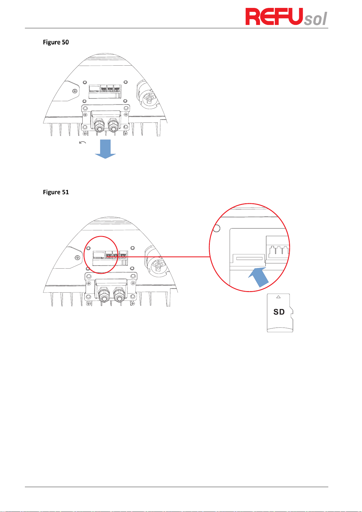
Step 1
first, turn off the DC and AC breaker, and then remove the communication waterproof
cover as the following picture. If the communication lines (RS485, Relays, I/O) has been
connected, Be sure to release the waterproof nut, Make sure the communication line is no
longer the force. Then remove the waterproof cover, In order to avoid loosening the
communication plug, which has been connected.
REFUone 3K-2T, 5K-2T, 7K-2T
48
Step 2
Remove the waterproof cover, Press SD card inside in the position marked SD card.
Then the SD card will automatically pop up.
Step 3
The SD card reader must be ready by the users, so that SD card so easy to establish the
connection with the computer.
Step 4
REFU will send the Software code to the user who needs to update. After user receive
the file, please decompressing file and cover the original file in SD card.
Step 5
Insert the SD card into the SD card slot, there will be a faint clicking sound typically,
indicating that has stuck.
Step 6
Then turn on DC switch and enter into the online upgrade to the main menu „5.
Software Update” in the LCD display program [6.3(E)]. The method to enter the menu can refer
to operation interface of LCD.
Step 7
Input the password, if password is correct, the update process begins; the original
password is 0715.
Step 8
System update main DSP, slave DSP and ARM in turns. If main DSP update success,the
LCD will display „Update DSP1 Success”, otherwise display „Update DSP1 Fail”; If slave DSP
update success ,the LCD will display „Update DSP2 Success”, otherwise display „Update DSP2

REFUone 3K-2T …7K-2T
49
Fail”.
Step 9
If fail, please turn off the DC breaker, wait for the LCD screen extinguish, then turn on
the DC breaker again, then Continue to update from step 6.
Step 10
After the update is completed, turn off the DC breaker, wait for the LCD screen
extinguish, then recover the communication waterproof and then turn on the DC breaker and
AC breaker again, the inverter will enters the running state.
REFUone 3K-2T, 5K-2T, 7K-2T
50
7
Trouble shooting and maintenance
Outlines of this chapter
This topic describes how to perform daily maintenance and troubleshooting to ensure
longterm proper operation of the inverter.
7.1
Trouble shooting
This section contains information and procedures for solving possible problems with the
inverter.
This section help users to identify the inverter fault. Please read the following procedures
carefully:
Check the warning, fault messages or fault codes shown on the inverter screen, record all the
fault information.
If there is no fault information shown on the screen, check whether the following
requirements are met:
Is the inverter mounted in a clean, dry place with good ventilation?
Is the DC switch turned ON?
Are the cables adequately sized and short enough?
Are the input and output connections and wiring in good condition?
Are the configuration settings correct for the particular installation?
Are the display panel and the communication cables properly connected and undamaged?
Follow the steps below to view recorded problems:
Press „ESC” to enter the main menu from the standard interface. Select „2. Event List”, then
press „OK” to enter event list.
7.1.1
EventList information
Table 8 Eventlist
Event
List No.
EventList Name
EventList description
Solution
ID01
GridOVP
The power grid voltage
is too high
If the alarm occurs occasionally, the possible cause is
that the electric grid is abnormal occasionally.
Inverter automatically returns to normal operating
status when the electric grid is back to normal.
ID02
GridUVP
The power grid voltage
is too low
If the alarm occurs frequently, check whether the grid
voltage/frequency is within the acceptable range. If
no, contact technical support. If yes, check the AC
circuit breaker and AC wiring of the inverter.
ID03
GridOFP
The power grid
frequency is too high
If the grid voltage/frequency is within the acceptable
range and AC wiring is correct, while the alarm occurs
repeatedly, contact technical support to change the
grid over-voltage, under-voltage, over- frequency,

REFUone 3K-2T …7K-2T
51
under-frequency protection points after
ID04
GridUFP
The power grid
frequency is too low
Obtaining approval from the local electrical grid
operator.
ID05
PVUVP
The input voltage is too
low
Check whether too few PV modules are series
connected in a PV string, thus the voltage (Vmp) of
the PV string is lower than the minimum operating
voltage of inverter. If yes, adjust the number of series
connected PV modules to increase the voltage of the
PV string to fit the input voltage range of inverter.
Inverter automatically returns to normal operating
status after correct adjustments.
ID09
PvOVP
The input voltage is too
high
Check whether too many PV modules are series
connected in a PV string, thus the voltage (Voc) of the
PV string is higher than the maximum input voltage of
inverter. If yes, adjust the number of series
connected PV modules to decrease the voltage of the
PV string to fit the input voltage range of inverter.
Inverter automatically returns to normal operating
status after correct adjustments.
ID10
IpvUnbalance
Input current is not
balanced
Check the input mode (parallel mode/ independent
mode) setting of inverter according to Section 0.
Input Mode of this user manual, If it’s incorrect,
change it according to Section 0. Set Input mode of
this manual.
ID11
PvConfigSetWrong
Incorrect input mode
ID12
GFCIFault
GFCI Fault
If the fault occurs occasionally, the possible cause is
that the external circuits are abnormal occasionally.
Inverter automatically returns to normal operating
status after the fault is rectified.
If the fault occurs frequently and lasts a long time,
check whether the insulation resistance between the
PV array and earth (ground) is too low, then check
the insulation conditions of PV cables.
ID14
HwBoostOCP
The input current is too
high, and h as happen
hardware protection
Check whether the input current is higher than the
maximum input current of inverters, then check the
input wiring, if both are correct, please contact
technical support.
ID15
HwAcOCP
The grid current is too
high, and has happen
hardware protection
ID15-ID24 are internal faults of inverter, turn OFF the
„DC switch”, wait for 5 minutes, then turn ON the
„DC switch”. Check whether the fault is rectified. If
no, please contact technical support.
ID16
AcRmsOCP
The grid current is too
high
ID17
HwADFaultIGrid
The grid current
sampling error
ID18
HwADFaultDCI
The DCI sampling error
ID19
HwADFaultVGrid
The grid voltage
sampling error
ID20
GFCIDeviceFault
The GFCI sampling error
REFUone 3K-2T, 5K-2T, 7K-2T
52
ID21
MChip_Fault
The master chip fault
ID22
HwAuxPowerFault
The auxiliary voltage
error
ID23
BusVoltZeroFault
The bus voltage
sampling error
ID24
IacRmsUnbalance
The Output current is
not balanced
ID25
BusUVP
The bus voltage Is too
low
If the PV array configuration is correct (no ID05 fault),
the possible cause is that the solar irradiance is too
low. Inverter automatically returns to normal
operating status after the solar irradiance returns to
normal level.
ID26
BusOVP
The bus voltage Is too
high
ID26-ID27 are internal faults of inverter, turn OFF the
„DC switch”, wait for 5 minutes, then turn ON the
„DC switch”. Check whether the fault is rectified. If
no, please contact technical support.
ID27
VbusUnbalance
The bus voltage is not
balanced
ID28
DciOCP
The Dci is too high
Check the input mode (parallel mode/ independent
mode) setting of inverter according to Section 0
(Input Mode) of this user manual, If it’s incorrect,
change it according to Section 0. Set Input mode of
this manual.
If the input mode is correct, turn OFF the „DC
switch”, wait for 5 minutes, then turn ON the „DC
switch”. Check whether the fault is rectified. If no,
please contact technical support, If it’s incorrect,
change it according to Section 6.3 (A) 10.Set Input
mode of this manual.
ID29
SwOCPInstant
The grid current is too
high
Internal faults of inverter, turn OFF the „DC switch”,
wait for 5 minutes, then turn ON the „DC switch”.
Check whether the fault is rectified. If no, please
contact technical support.
ID30
SwBOCPInstant
The input current is too
high
Check whether the input current is higher than the
maximum input current of inverters, then check the
input wiring, if both are correct, please contact
technical support.
ID49
Consistent
Fault_VGrid
The grid voltage
sampling value between
the master DSP and
slave DSP is not
consistent
ID49-ID55 are internal faults of inverter, turn OFF the
„DC switch”, wait for 5 minutes, then turn ON the
„DC switch”. Check whether the fault is rectified. If
no, please contact technical support.
ID50
Consistent
Fault_FGrid
The grid f requency
sampling value between
the master DSP and
slave DSP is not
consistent
ID51
Consistent
The DCI sampling value
between the master

REFUone 3K-2T …7K-2T
53
Fault_DCI
DSP and slave DSP is not
consistent
ID52
Consistent
Fault_GFCI
The GFCI sampling value
between the master
DSP and slave DSP is not
consistent
ID53
SpiCommLose
The spi communication
between the master
DSP and slave DSP is
fault
ID54
SciCommLose
The Sci communication
between the control
board communication
board is fault
ID55
RelayTestFail
The relays fault
ID56
PvIsoFault
The insulation
resistance is too low
Check the insulation resistance between the PV array
and earth(ground), if a short circuit occurs, rectify the
fault.
ID57
OverTemp
Fault_Inv
The inverter temp is too
high
Ensure the installation position and installation
method meet the requirements of Section 3.4 of this
user manual.
Check whether the ambient temperature of the
installation position exceeds the upper limit. If yes,
improve ventilation to decrease the temperature.
ID58
OverTemp
Fault_Boost
The Boost temp is too
high
ID59
OverTemp
Fault_Env
The environment temp
is too high
ID65
Unrecover
HwAcOCP
The grid current is too
high,and has cause
unrecoverable
hardware fault
ID65-ID70 are internal faults of inverter, turn OFF the
„DC switch”, wait for 5 minutes, then turn ON the
„DC switch”. Check whether the fault is rectified. If
no, please contact technical support.
ID66
Unrecover
BusOVP
The bus voltage is too
high, and has cause
unrecoverable fault
ID67
Unrecover
IacRms
Unbalance
The grid current is
unbalance, and has
cause unrecoverable
fault
ID68
Unrecover
IpvUnbalance
The input current is
unbalance, and has
cause unrecoverable
ID69
Unrecover
Vbus Unbalance
The bus voltage Is
unbalance, and has
cause unrecoverable
fault
ID70
Unrecover
OCPInstant
The grid current is too
high, and has cause
unrecoverable fault

REFUone 3K-2T, 5K-2T, 7K-2T
54
ID71
Unrecover
PvConfigSet Wrong
Incorrect input mode
Check the input mode (parallel mode/ independent
mode) setting of inverter according to Section 0
(Input Mode) of this user manual, If it’s incorrect,
change it according to Section 0. Set Input mode of
this manual.
ID74
Unrecover
IPVInstant
The input current is too
high,and has happen
unrecoverable fault
ID74-ID77 are internal faults of inverter, turn OFF the
„DC switch”, wait for 5 minutes, then turn ON the
„DC switch”. Check whether the fault is rectified. If
no, please contact technical support.
ID75
Unrecover
WRITEEEPROM
The EEPROM is
unrecoverable
ID76
Unrecover
READEEPROM
The EEPROM i s
unrecoverable
ID77
UnrecoverRelayFail
Relay has happen
permanent fault
ID81
OverTempDerating
the inverter has derated
because of the
temperature is too high
Ensure the installation position and installation
method meet the requirements of Section 3.4 of this
user manual.
Check whether the ambient temperature of the
installation position exceeds the upper limit. If yes,
improve ventilation to decrease the temperature.
ID82
OverFreqDerating
the inverter has derated
because of the grid
frequency too high
Inverter automatically reduce the output power
when the frequency of electrical grid is too high.
ID83
RemoteDerating
The inverter has
derated by the Remote
control
Inverter records ID83 in case of remote power
derating operation. Check the wiring of remote input
and output control signal port on the communication
board according to Section 4.5 of this user manual.
ID84
RemoteOff
The inverter has shut
down because by the
Remote control
inverter records ID84 in case of remote shutdown
operation. Check the wiring of remote input and
output control signal port on the communication
board according to Section 4.5 of this user manual.
ID94
Software version is
not consistent
The Software between
the control board and
the communication
board is not consistent
Contact technical support to upgrade software.
ID95
Communication
board EEPROM fault
The Communication
board EEPROM is fault
ID95~ID96 are internal faults of inverter, turn OFF the
„DC switch”, wait for 5 minutes, then turn ON the
„DC switch”. Check whether the fault is rectified. If
no, please contact technical support.
ID96
RTC clock chip
anomaly
RTC clock chip is fault
ID97
Invalid Country
The Country is InValid
Check the country setting according to Section 0
(Country) of this user manual, If it’s incorrect, change
it according to Section 0. Set Country Code of this
manual.
ID98
SD fault
The SD card is fault
Please replace the SD card.

REFUone 3K-2T …7K-2T
55
7.2
Maintenance
Inverters generally do not need any daily or routine maintenance. The heat sink should not be
blocked by dust, dirt or any other item.
Before the cleaning, make sure that the DC SWITCH is turned OFF and the circuit breaker
between inverter and electrical grid is turned OFF. Wait at least for 5 minutes before the
cleaning.
7.2.1
Inverter cleaning
Please clean the inverter with an air blower, a dry & soft cloth or a soft bristle brush. Do NOT
clean the inverter with water, corrosive chemicals, detergent, etc.
7.2.2
Heat sink cleaning
For the long-term proper operation of inverters, ensure there is enough space around the heat
sink for ventilation, check the heat sink for blockage (dust, snow, etc.) and clean them if they
exist. Please clean the heat sink with an air blower, a dry & soft cloth or a soft bristle brush. Do
NOT clean the heat sink with water, corrosive chemicals, detergent, etc.
REFUone 3K-2T, 5K-2T, 7K-2T
56
8
Technical data
Outlines of this chapter
This topic lists the technical specifications for all REFUone inverters.
8.1
DC Data
Technical Data
3K-2T
5K-2T
7K-2T
Max. input power (W)
3,500
5,500
8,300
Number of independent MPPT
2
Number of DC inputs MPPT 1 / 2
1 / 1
1 / 1
2 / 1
Max input voltage (V)
600
Start-up input voltage (V)
120
Rated input voltage (V)
360
Operating input voltage range (V)
90 … 580
Full power MPPT voltage range (V)
160 … 520
250 … 520
250 … 520
Max Power Input 1 / Input 2 (W)
2,000 / 2,000
3,000 / 3,000
5,000 / 2,500
Max. MPPT current MPPT 1 / 2 (A)
11 / 11
2 x 11 / 11
Max. Short circuit current ISC MPPT 1 / 2 (A)
13.2 / 13.2
26.4 / 13.2
8.2
AC Data
Technical Data
3K-2T
5K-2T
7K-2T
Rated power (@220 V, 50 Hz) (W)
3,000
5,000
7,500
Max AC power (VA)
3,000
5,000
7,500
Nominal Grid voltage (V)
220
Grid voltage range (V)
180 … 276 (According to local standard)
Grid frequency range (Hz)
44 … 55 / 54 … 66 (According to local standard)
Active power adjustable range (%)
0 … 100
Max output current (A)
13.7
22.8
32.6
THDi (%)
<3
Power factor
1 (adjustable +/- 0.8)
8.3
Efficiency, Protection and Communication
Technical Data
3K-2T
5K-2T
7K-2T
Max efficiency (%)
97.6
97.8
98.2
Weighted eff. (EU/CEC) (%)
97.2
97.3
97.6
Self-consumption at night (W)
<1
Feed-in start power (W)
50
MPPT efficiency
>99.9%
DC switch
integrated
Safety protection
Anti-islanding, RCMU, Ground fault monitoring
Communication Ports
Standard: RS485, WiFi
Optional: GPRS, Ethernet

REFUone 3K-2T …7K-2T
57
Protection class
Class I
External environment pollution degree
Degree 3
Overvoltage category
PV: OVC II, AC mains: OVC III
Max inverter Back-feed current to the array (A)
0
Output short circuit current and duration
200 A / 1 µs
Output inrush current and duration
0.8 A / 2 µs
8.4
General Data
Technical Data
3K-2T
5K-2T
7K-2T
Ambient temperature range (°C)
-25 … +60 (above 45 derating)
Topology
Transformerless
Degree of protection
IP65
Allowable relative humidity range (%)
0 … 100
Max operating latitude (m above Sea Level)
2000
Noise (dB)
<25
Weight (kg)
11.5
18
Cooling
Natural passive cooling
Dimension (H x W x D) (mm)
437 x 324 x 130
467 x 352 x 157
Certification
INMETRO (ABNT NBR 16149:2013, ABNT NBR
16150:2013,
ABNT NBR IEC 62116:2012), IEC 62116, IEC 61727,
IEC 61683, IEC 60068 (1,2,14,30), IEC 62109-1/2, VDE
0126-1-1:2013
Warranty
5 years

REFUone 3K-2T, 5K-2T, 7K-2T
58
9
Quality Assurance
REFU Elektronik GmbH offers 5 years product warranty for REFUone inverters from date of
installation. However, the warranty period can’t exceed 66 months from the date of delivery
of the inverter. During the warranty period, REFU Elektronik GmbH guarantees normal
operation of the inverter.
If during the warranty period, the inverter develops fault, please contact your installation
contractor or supplier. In case of faults falling within manufacturers’ responsibility, REFU
Elektronik GmbH will provide service and maintenance free of any charge.
Disclaimer
Use of REFU inverters for any other purpose than its intended for; Faulty system design
or installation;
Improper operation;
Wrong protection settings of the inverter; Unauthorized modification of the inverter;
Damage caused by external factors or force majeure (violent or stormy weather,
lightning, over- voltage, fire, earthquake, tsunami etc.).

REFUone 3K-2T …7K-2T
59
10
Technical Support
If you have followed the Trouble shooting and could not solve your issue, you can contact
REFU’s service team as follows:
Brazil: +55 (11) 4235-9377
Germany +49 (7121) 4332-333
Webpage: www.refu.com/refuone
Download of Data sheets, Manuals, Certificates, Firmware Update Files etc.
E-mail: service.brasil@refu.com

REFU Elektronik GmbH
Marktstraße 185
D-72793 Pfullingen
Phone: +49 (0)7121-4332 0
Fax: +49 (0)7121-4332 140
Mail: info@refu.com
Version 4 (No. 982065) 801 Series June 2019
 Loading...