

Page 1
Bedienungsanleitung
MSat-65
Lesen Sie die gesamte Anleitung des Gerätes sorgfältig durch, bevor Sie das Gerät
benutzen. Bewahren Sie die Anleitung für den weiteren Gebrauch gut auf.
Page 2

ALLGEMEIN
Das Gerät MSat-65 wurde entwickelt, um auch Straßenfahrzeugen wie z.B.
Wohnwagen, Minibusse, Transporter und LKWs den vollen Komfort eines
Vollautomatischen Satelliten Systems bieten zu können.
WICHTIGE SICHERHEITSHINWEISE
Entfernen Sie nie die Abdeckung. Es befinden sich keine Teile im Inneren, die
vom Benutzer selbst repariert werden können.
Das Öffnen der Abdeckungen hebt die Garantie für das Gerät auf.
Führen Sie Reparaturen niemals selbst durch. Für Reparaturen wenden Sie
sich an den Herstellerservice oder Ihren Fachhändler.
Es wird empfohlen die Montage der Satelliten Anlage an Ihrem Camping
wagen oder anderen Plätzen durch einen Fachhändler oder einer
Fachwerkstatt vornehmen zu lassen. Eine nicht korrekt ausgeführte
Installation der Satelliten-Anlage kann zu Beschädigungen an der Antenne und
z.B. an Ihrem Fahrzeug führen.
Bitte prüfen Sie stets vor dem Losfahren, dass die Antenne eingefahren ist.
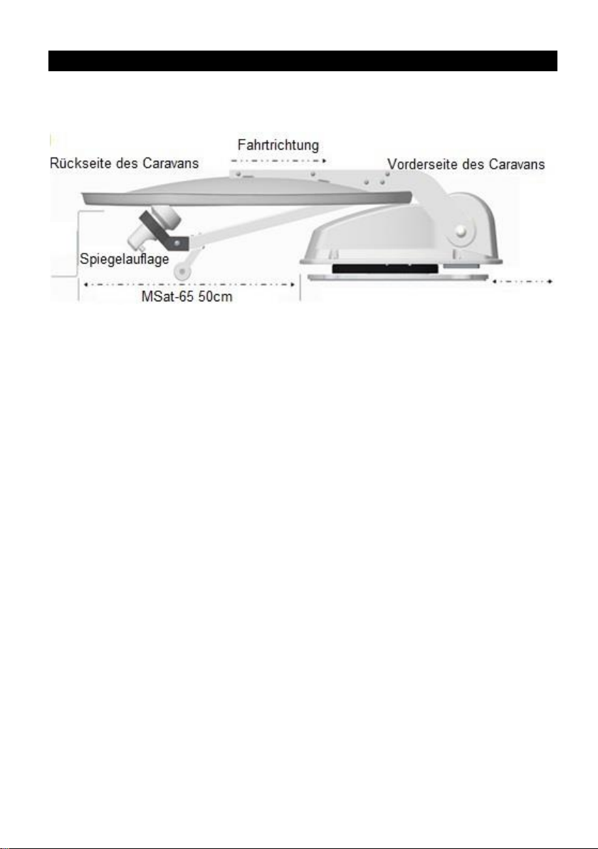
Die Antenne immer gegen die Fahrtrichtung montieren.
Dieses System ist nicht geeignet für die Verwendung, während das Fahrzeug
in Bewegung ist. Die Verwendung während der Fahrt kann zu Schäden am
Fahrzeug, sowie zu Sach- oder Personenschäden führen.
Das Steuergerät sollte nicht in der Nähe von Hitzequellen, wie z.B. Öfen,
Heizungen positioniert werden, vermeiden Sie Hitzestau am Gerät.
Wenn die Antenne mit Schnee oder Eis bedeckt ist, darf das System nicht
betrieben werden. Diese Art der Nutzung kann zu dauerhaften Schäden am
System führen.
Beachten Sie bitte, dass sich durch die Antenne die Fahrzeughöhe
entsprechend ändert, für den ordnungsgemäßen und reibungslosen Betrieb
ist der Nutzer verantwortlich.
Beachten Sie vor dem Montieren der Antenne, dass die Tragelast vom
gewählten Montagepunkt dem Gewicht der Antenne entspricht. Kontaktieren
Sie gegeben falls Ihren Händler oder den Fahrzeughersteller für mehr
Informationen.
Page 3

WICHTIGE SICHERHEITSHINWEISE
Bitte beachten Sie das am Montageplatz der Antenne und ca. 40cm im
Umkreis der Rotationsbewegung bei der Satellitensuche sich keine
Hindernisse befinden die zu Beschädigungen führen können.
Das Fahren mit ausgefahrener Antenne ist nicht gestattet. Hierdurch können
Beschädigungen an dem System oder Ihrem Fahrzeug entstehen.
Geschwindigkeiten über 130kmh sind nicht zulässig. Es kann bei höheren
Geschwindigkeiten zu Beschädigung führen.
Die Satelliten Anlage ist nicht für automatische Waschstraßen geeignet.
Bei Gewitter trennen Sie das Steuergerät von der Satelliten Anlage.
Beigefügte Kabel dürfen nicht über scharfe Kanten geführt werden und nicht
geknickt werden.
Nicht fachgerechte Gerätebezogene Handhabung führt zum Verlust der
Garantie.
Für die Garantieabwicklung oder bei Fragen wenden Sie sich an Ihren
Fachhändler oder den Herstellerservice.
Page 4

LIEFERUMFANG
Motoreinheit und Spiegel
Steuergerät
Mini-Kontrolleinheit
Dachdurchführung mit verbundenen Kabeln
2,5 Meter Steuerkabel
2,5 Meter Antennenanschlusskabel
1,5 Meter Antennenanschlusskabel
Spiegelauflage
Installationsanleitung
Hinweis:
- Kontrollieren Sie nach Erhalt des Gerätes, den Lieferumfang auf
Vollständigkeit.
- Das Montagematerial (z.B. Schrauben, Unterlegscheiben, Muttern,
Montagekleber und Dichtungsmasse) sind nicht im Lieferumfang enthalten.
INSTALLATIONSANWEISUNG
Es wird empfohlen die Montage / Installation von einem Fachhändler oder
Fachwerkstatt vornehmen zu lassen!
Page 5
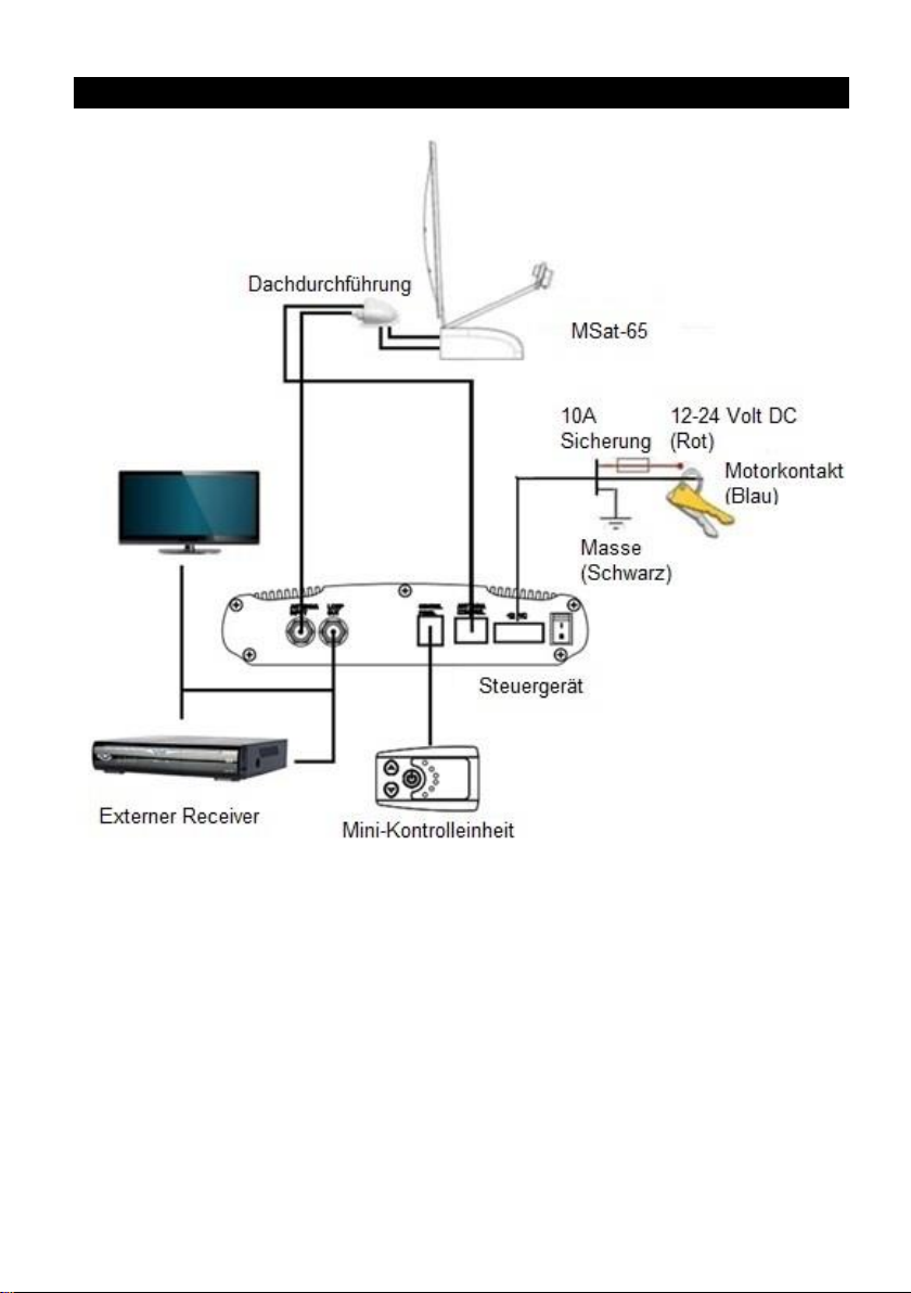
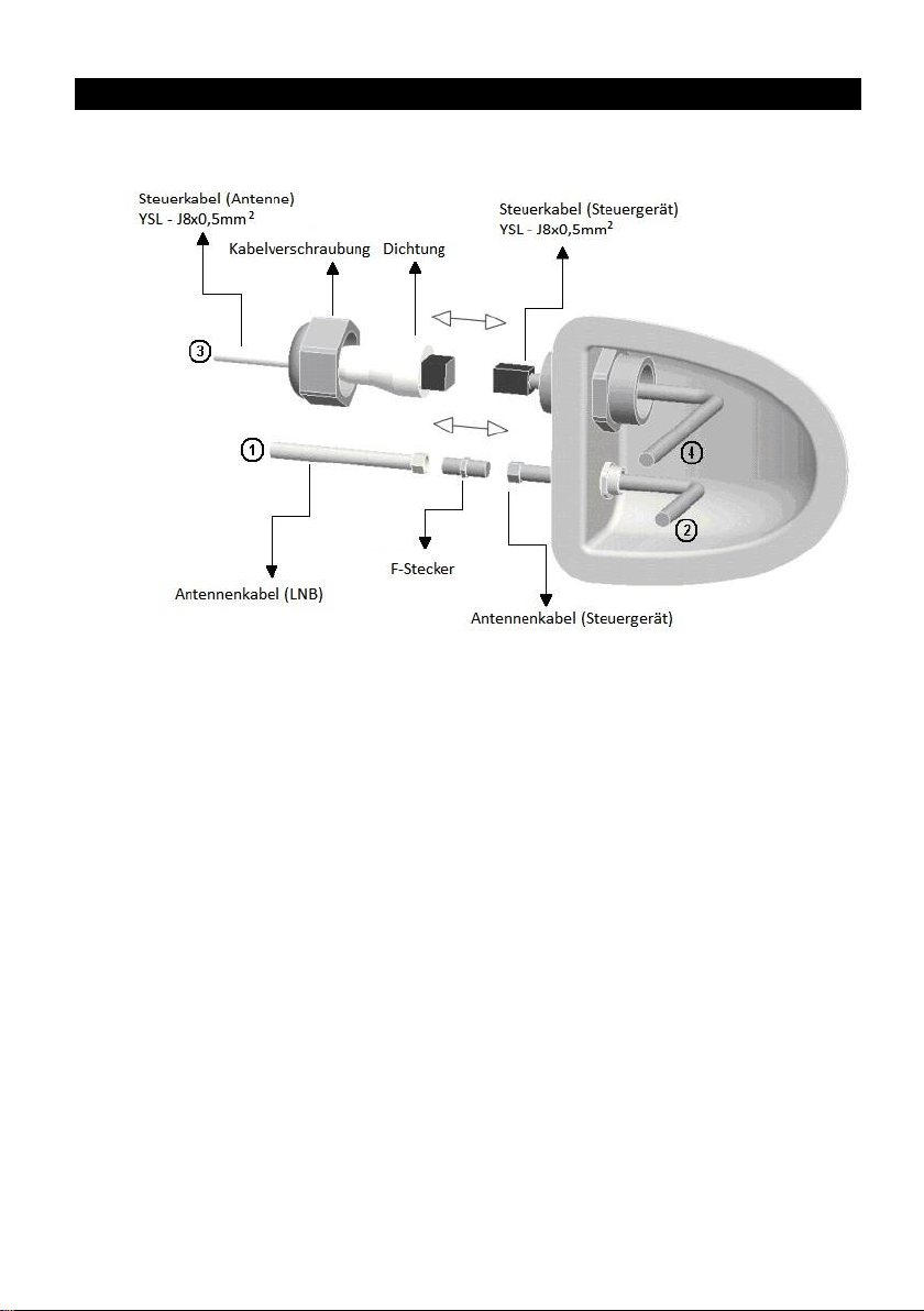
ANSCHLUSSDIAGRAMM
Page 6
MONTAGE / INSTALLATIONS VORBEREITUNG
Stellen Sie sicher, dass sich keine physikalischen Hindernisse am Montageort
befinden, die die Bewegung der Satellitenanlage beeinträchtigen können.
Erkundigen Sie sich bei Ihrem Fahrzeughersteller oder Fachhändler, ob der Ort
für die Installation der Satellitenanlage geeignet ist.
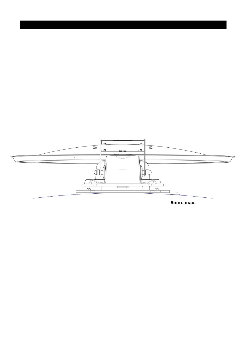
Achten Sie darauf, dass die Montagefläche eben.
Berücksichtigen Sie beim auswählen des Montageortes die Kabelführung ins
Innere des Fahrzeugs.
Vergewissern Sie sich vor der Montage der Antenne das alle benötigten
Materialien bereitliegen.
Vermeiden Sie unebene Montageflächen bzw. gleichen Sie diese aus.
Page 7
INSTALLATION AUF DEM DACH
1. Säubern Sie die Montagefläche mit einem geeigneten Reiniger.
2. Der Spiegel und die LNB-Einheit müssen bei der Montage zur Rückseite des
Fahrzeuges zeigen.
Hinweis: Sorgen Sie für eine sichere Montage der Satellitenanlage durch Verschrauben
und ggf. durch zusätzlichem Verkleben mit passenden Montagekleber.
1. Montage mit Schrauben:
a) Übertragen Sie die Montagepunkte der Montageplatte auf das
Fahrzeugdach und bohren Sie die entsprechenden Löcher.
b) Befestigen Sie die Montageplatte sicher auf dem Dach.
c) Zur Abdichtung der Montageschrauben verwenden Sie
handelsübliche Karosseriedichtmasse.
d) Befestigen Sie die Spiegelauflage so, dass die Satellitenschüssel im
eingefahrenen zustand Waagerecht aufliegt.
2. Montage zusätzlich mit Klebstoff:
a) Übertragen Sie den Umriss der Montageplatte möglichst im
angeschraubten Zustand zur Fixierung auf das Fahrzeugdach.
b) Nach dem lösen der Schrauben Säubern Sie die den markierten
Bereich und die Montageplatte.
c) Rauen Sie den Untergrund leicht an und tragen Sie den
Montagekleber gleichmäßig auf.
d) Drücken Sie die Anlage gleichmäßig auf die Montagefläche.
e) Schrauben Sie die Antenne anschließend wieder fest.
f) Beachten Sie die Trocknungszeit des eingesetzten Klebstoffs.
g) Zur Abdichtung der Montageschrauben verwenden Sie
handelsübliche Karosseriedichtmasse.
h) Entfernen Sie überschüssige Klebstoffreste.
Page 8
INSTALLATION AUF DEM DACH
3. Montage der Kabeldurchführung:
a) Übertragen Sie den Umriss der Kabeldurchführung auf das
Fahrzeugdach.
b) Bohren Sie die entsprechenden Löcher zur Kabeldurchführung in das
Fahrzeug innere.
c) Dichten Sie die die Kabeldurchführung ab.
d) Kleben Sie die Kabeldurchführung mit geeignetem Montagekleber
auf das Fahrzeugdach.
e) Beachten Sie die Trocknungszeit des eingesetzten Klebstoffs.
f) Entfernen Sie überschüssige Klebstoffreste.
Hinweis: Vergewissern Sie sich vor dem bohren der Löcher, dass darunter liegende
Gegenstände / Leitungen nicht beschädigt werden können. Für die entsprechenden
Informationen wenden Sie sich ggf. an Ihren Fachhändler oder den Fahrzeughersteller.
Page 9
INSTALLATION IM FAHRZEUG
1. Sorgen Sie für möglichst kurze Kabelverbindungen innerhalb des Fahrzeugs.
2. Positionieren Sie das Steuergerät in der Nähe Ihres TV Gerätes.
3. Montieren Sie das Steuergerät möglichst waagerecht.
4. Das Steuergerät sollte nicht mit einem abschirmenden Metallgehäuse
abgedeckt werden.
a) Schließen Sie das Antennenkabel an den entsprechenden Eingang
[ANTENNA INPUT] vom Steuergerät an.
b) Verbinden Sie den Fernseher / Receiver durch ein Antennenkabel mit
dem Ausgang [LOOP OUT] vom Steuergerät.
c) Schließen Sie das Kabel von der Mini Kontrolleinheit an den
Anschluss [Control Panel] an.
d) Verbinden Sie das ankommende Steuerkabel mit dem Anschluss
[Motor Control].
5. Verbinden Sie den Satelliten Empfänger mit der elektrischen Fahrzeugmasse.
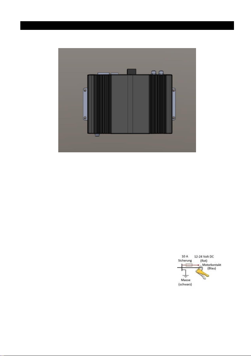
6. Verbinden Sie das Steuergerät mit der abgesicherten 12/24V DC
Spannungsversorgung Ihres Fahrzeugs.
- 12-24 Volt DC: Rotes Kabel
- Motorkontakt: Blaues Kabel
- Masse: Schwarzes Kabel
Page 10

FEHLERBEHEBUNG
Während des normalen Betriebs zeigt die Mini-Kontrolleinheit den gewählten
Satelliten an. Bei ertönen des Alarmtons haben die LEDs, wie unten beschrieben,
verschiedene Bedeutungen. Die Mini-Kontrolleinheit hat verschiedene
Fehlermeldungen, um den Nutzer anzuzeigen wodurch der Fehler ausgelöst
wurde. Jeder Alarm erfolgt mit einem Alarmton und leuchten der LEDs.
- Fehler-1 (LED Astra 1 leuchtet + Alarmton): Höhengeberfehler beim Öffnen.
Überprüfen Sie das Motorkabel am Steuergerät und an der Antenne.
- Fehler-2 (LED Hotbird leuchtet + Alarmton): Höhengeberfehler beim
Schließen. Überprüfen Sie das Motorkabel am Steuergerät und an der
Antenne.
- Fehler-3 (LED Astra 1, Hotbird leuchten + Alarmton): Die Antenne kann die
Azimut-Schalter nicht erreichen. Überprüfen Sie, ob ein Hindernis die
Bewegung der Antenne verhindert.
- Fehler-4 (LED Astra 2 leuchtet + Alarmton): Azimut-Motorunterbrechung in
Schließrichtung (bei 0°). Überprüfen Sie das Motorkabel am Steuergerät und
an der Antenne.
- Fehler-5 (LED Astra 1, Astra 2 leuchten + Alarmton): Azimut-Motorleerlauf in
Öffnungsrichtung (bei 360°) Überprüfen Sie das Motorkabel am Steuergerät
und an der Antenne.
- Fehler-6 (LED Hotbird, Astra 2 leuchten + Alarmton): Elevation-Motor –
offener Stromkreis in Schließrichtung (bei 0°) Überprüfen Sie das Motorkabel
am Steuergerät und an der Antenne.
- Fehler-7 (LED Astra1, Hotbird, Astra 2 leuchten + Alarmton): Elevation-Motor
– offener Stromkreis in Öffnungsrichtung (bei 180°) oder das Motorkabel ist
nicht angeschlossen. Überprüfen Sie, ob das Motorkabel angeschlossen ist.
- Fehler-8 (LED Astra 3 leuchtet + Alarmton): LNB ist nicht angeschlossen oder
defekt. Prüfen Sie, ob das LNB Kabel an dem Steuergerät und am LNB
angeschlossen ist.
- Fehler-9 (LED Astra1, Astra 3 leuchten + Alarmton): Smartsearch Fehler,
Sensorfehler oder GPS Fehler. Prüfen Sie, ob das Motorkabel angeschlossen
ist. Prüfen Sie ebenfalls, ob die Pins des Kabels beschädigt sind.
- Fehler-10 (LED Hotbird, Astra 3 leuchten + Alarmton): Azimut-Encoder-
Fehler. Überprüfen Sie das Motorkabel am Steuergerät und an der Antenne.
- Fehler-11 (LED Astra 1, Hotbird, Astra 2, Astra 3 leuchten + Alarmton):
Azimut Motor Überstrom. Prüfen Sie, ob ein Hindernis die Bewegung der
Antenne behindert.
Page 11

FEHLERBEHEBUNG
- Fehler-12 (LED Astra2, Astra 3 leuchten + Alarmton): Höhenmotor
Überstrom. Prüfen Sie, ob ein Hindernis die Bewegung der Antenne
behindert.
- Fehler-13: Antenne findet keinen Satelliten. Prüfen Sie, ob ein Hindernis
(Baum, Haus) den Empfang behindert.
HINWEIS:
- Bei angelegter 12V Spannung am Kontaktkabel (blau) ertönt dreimal der
Alarm und die Antenne schließt sich.
- Azimut ist der Winkel für die horizontale (links/rechts) Ausrichtung der Sat-
Antenne.
APP STEUERUNG
APP INSTALLATION
1. Laden Sie die App [MotosatRC] im „AppStore“ oder „GooglePlay“ herunter.
2. Folgen Sie den Anweisungen.
VERBINDUNG MIT DER CONTROLBOX
1. Halten Sie die [Standby] Taste so lange gedrückt bis ein „Piepton“ zu
hören ist um das Gerät in den Kopplungs- Modus zu bringen.
2. Öffnen Sie die „MotosatRC“ App und warten Sie, bis die „Steuerbox“
erkannt wird.
3. Bestätigen Sie die Eingabe, um die Geräte zu verbinden.
HINWEIS: Der Verbindungsprozess muss nur bei der ersten Benutzung erfolgen.
Standby Button
Page 12

MOTOSAT RC MOBILE APP EIGENSCHAFTEN
Kontrolleinheit
1. Satellitenwechsel: Hoch / Runter
2. Antenne öffnen / schließen.
3. Menü
4. Firmenwareupdate.
5. Satelliteninformationen.
6. Manuelle Einstellungen.
7. Synchronisation der Steuerbox.
8. System Information.
Page 13

MOTOSAT RC MOBILE APP EIGENSCHAFTEN
9. Ausgewählter Satellit.
10. Um die Antenne manuell auszurichten, nutzen Sie die Pfeiltasten [▲▼◄►].
11. Beenden Sie die Verbindung zum Steuergerät.
12. Fehlermeldung.
Page 14

BEDIENUNG
Erster Start des Systems
a) Vergewissern Sie sich, dass das Steuergerät richtig angeschlossen ist.
b) Betätigen Sie den Kippschalter.
c) Drücken Sie die Standby Taste um das Gerät einzuschalten.
Antenne Einschalten
a) Betätigen Sie die [Power] Taste an der Mini-Kontrolleinheit, die rote LED geht
an und das System beginnt zu arbeiten.
b) Auf der Mini-Kontrolleinheit wird der ausgewählte Satellit angezeigt.
c) Die Satelliten-Anlage beginnt automatisch mit Suche nach dem ausgewählten
Satelliten.
d) Die Suche kann in der Regel 1-2 Minuten dauern.
e) Nach erfolgreicher Ausrichtung wird am TV ein Fernsehbild angezeigt.
Antenne ausschalten
a) Um das System auszuschalten und die Antenne einzufahren betätigen Sie die
Power-Taste auf der Mini-Kontrolleinheit.
b) Die Antenne wird vollautomatisch eingefahren.
c) Wenn die Blaue LED auf der Mini-Kontrolleinheit ausgeht, ist die Antenne
vollständig geschlossen.
d) Um das Gerät vollständig vom Strom zu trennen betätigen Sie den
Kippschalter an dem Steuergerät.
Hinweis
Objekte wie Bäume, Brücken und große Häuser, die sich im Einfallswinkel des
Satelliten befinden, können zur Beeinträchtigung des Signals führen.
Starker Regen, Wolken, Schnee oder Eis können die Empfangsqualität reduzieren.
Wenn das Satellitensignal verloren geht, friert das Fernsehbild ein oder verschwindet.
Page 15

TECHNISCHE SPEZIFIKATIONEN: MSat65
Motorsteuerung: 2-Achsen DC Motor
Satellitensuche: Automatisch
Verbindungen: Antenne / Steuerung Kabel
Suchwinkel: 0° ~ 380° begrenzt
Drehgeschwindigkeit: 20° / Sekunde
Neigungswinkel: 0° ~ 75°
Neigungsgeschwindigkeit: 10° / Sekunde
Antenne (L x B x H): 87 x 66 x 19cm
Gewicht: 14Kg
Spannungsversorgung: 12 / 24V DC 5A
Stromverbrauch (max.): 30W
Temperaturbereich: -15°C ~ +50°C
(Lagernd -30°C ~ +70°C)
Luftfeuchtigkeit im Betrieb: 0~98%
Alle Angaben ohne Gewähr.
Änderungen von Design und Spezifikation auch ohne Vorankündigung vorbehalten
ENTSORGUNGSHINWEISE
Dieses Symbol auf dem Gerät und / oder Zubehör bedeutet, dass das Gerät
sowie Elektrische- und Elektronische Geräte am Ende seiner Lebensdauer
getrennt von Ihrem Hausmüll entsorgt werden müssen. Es gibt getrennte
Sammelsysteme für das Recycling in der EU. Für weitere Informationen
wenden Sie sich bitte an die örtliche Behörde oder Ihren Fachhändler.
VEREINFACHTE EU-KONFORMITÄTSERKLÄRUNG
Hiermit erklärt die UltraMedia GmbH & Co. Handels KG, dass das Gerät MSat-65 der
Richtlinie 2014/53/EU entspricht.
Den vollständigen Text der EU Konformitätserklärung können Sie per email anfordern.
Die email Adresse lautet: info@ultramedia.de
Wir wünschen Ihnen viel Freude mit dem Gerät
Ihr UltraMedia Team
Page 16

GARANTIEKARTE
MSat-65
Sehr geehrte Kundin, sehr geehrter Kunde,
vielen Dank, dass Sie sich für eines unserer Produkte entschieden haben. Unsere Produkte
unterlaufen im Zuge der Produktion eine genaue Qualitätskontrolle.
Sollte Ihnen eines unserer Geräte dennoch Anlass zur Reklamation geben oder Sie haben Fragen
zu einem unserer Geräte, rufen Sie gerne unseren Kunden-Support an.
Auf dieses Gerät geben wir eine Gewährleistung von 24 Monaten ab Kaufdatum.
Außerhalb der Gewährleistung bieten wir Ihnen eine kostenpflichtige Reparatur nach
Kostenvoranschlag an. Bitte setzen Sie sich vor dem Einsenden mit unserem Kunden-Support in
Verbindung.
Bitte haben Sie Verständnis, dass die Gewährleistung nur für Geräte die innerhalb des
Gewährleistungszeitraums bei uns eingehen berücksichtigt werden kann.
Die Gewährleistung bezieht sich auf Material und Produktionsfehler. Während der
Gewährleistung wird Ihr Gerät repariert bzw. ausgetauscht. Eine Erstattung des Kaufbetrags ist
durch die Firma UltraMedia leider nicht möglich. Ausgeschlossen von der Gewährleistung sind
Beschädigungen, die durch unsachgemäßen Gebrauch, durch die Nutzung von Fremdzubehör,
Sturz-, Staub-, Wasserschäden und Verschleißerscheinungen (z.B. Kratzer, optische
Abnutzungen), die durch den Kunden oder Fremdeinwirkungen hervorgerufen worden sind.
Um die Gewährleistungsansprüche geltend zu machen, senden Sie das Gerät mit kompletten
Zubehör, einer Rechnungskopie und der Fehlerbeschreibung an die unten angegebene Adresse
ein. Bitte vergessen Sie für eventuelle Rückfragen nicht Ihre komplette Anschrift, eine
Telefonnummer / E-Mail Adresse mit anzugeben.
Der Versand zu uns findet auf eigene Kosten statt. Unfreie Pakete können nicht angenommen
werden und gehen an den Absender zurück.
Bitte verpacken Sie das Gerät ausreichend transportsicher. Für Transportschäden, die auf dem
Transportweg zu uns entstehen, übernimmt die Firma UltraMedia keine Haftung. Nach Erhalt
Ihrer Einsendung werden wir Ihr Gerät schnellstmöglich bearbeiten und an Sie zurück senden.
Bitte setzen Sie sich vor dem Einsenden Ihres Gerätes mit unserem Kunden-Support oder Ihrem
Fachhändler in Verbindung, da sich viele Probleme auch telefonisch lösen lassen können.
UltraMedia GmbH & Co. Handels KG service@ultramedia.de
Friedrich-Penseler-Str. 28 Tel.: +49 / (0) 4131/9239-20
D-21337 Lüneburg Mo.-Do.: 08:00-17:00
http://www.ultramedia.de Fr.: 08:00-14:30
Page 17

User Manual
MSat-65
Read the entire manual of the device carefully before using the device. Keep the
instructions in a safe place for further use.
Page 18

GENERAL
The MSat-65 device was developed to also use road vehicles such as Caravans,
minibuses, vans and trucks can offer the full convenience of a fully automatic satellite
system.
IMPORTANT SAFETY INSTRUCTIONS
Never remove the cover. There are no internal parts that can be repaired by
the user.
Opening the covers invalidates the guarantee for the device.
Never carry out repairs yourself. For repairs, contact the manufacturer's
service or your specialist dealer.
It is recommended to have the satellite system installed on your camping car
or other locations by a specialist dealer or a specialist workshop. Incorrect
installation of the satellite system can damage the antenna and e.g. on your
vehicle.
Always check that the antenna is retracted before driving off.
Always mount the antenna against the direction of travel.
This system is not suitable for use while the vehicle is in motion. Use while
driving can result in damage to the vehicle, property damage or personal
injury.
The control unit should not be near heat sources such as Stoves, heaters are
positioned, avoid heat build-up on the device.
The system must not be operated if the antenna is covered with snow or ice.
This type of use can lead to permanent damage to the system.
Please note that the antenna changes the vehicle height accordingly, the user
is responsible for the proper and smooth operation.
Before mounting the antenna, make sure that the load on the selected
mounting point corresponds to the weight of the antenna. If necessary,
contact your dealer or the vehicle manufacturer for more information.
Please note that there are no obstacles at the antenna installation site and
approx. 40 cm around the rotational movement when searching for satellites
that can lead to damage.
Driving with the antenna extended is not permitted. This can damage the
system or your vehicle.
Speeds above 130kmh are not permitted. It can cause damage at higher
speeds.
The satellite system is not suitable for automatic car washes.
In the event of a thunderstorm, separate the control unit from the satellite
system.
Attached cables must not be run over sharp edges and must not be kinked.
Page 19

IMPORTANT SAFETY INSTRUCTIONS
Improper handling of the device will invalidate the guarantee.
For warranty processing or if you have any questions, contact your specialist
dealer or the manufacturer's service.
PACKAGE CONTENTS
Motor unit and mirror
Control unit
Mini control unit
Roof duct fort he cables
2,5 meter control cable
2,5 Meter antenna connection cable
1,5 Meter antenna connection cable
Mirror pad
User manual
Note:
- After receiving the device, check that the scope of delivery is complete.
- The assembly material (e.g. screws, washers, nuts, assembly adhesive and
sealing compound) are not included in the scope of delivery.
INSTALLATION INSTRUCTION
It is recommended to have the assembly / installation carried out by a
specialist dealer or specialist workshop!
Page 20

CONNECTION DIAGRAM
Page 21

ASSEMBLY / INSTALLATION PREPARATION
Make sure that there are no physical obstacles at the installation site that
could impair the movement of the satellite system.
Ask your vehicle manufacturer or specialist dealer whether the location is
suitable for the installation of the satellite system.
Make sure that the mounting surface is level.
When choosing the installation location, take the cable routing into the
interior of the vehicle.
Before installing the antenna, make sure that you have all the materials you
need.
Avoid or compensate for uneven mounting surfaces.
INSTALLATION ON THE ROOF
1. Clean the mounting surface with a suitable cleaner.
2. The mirror and the LNB unit must face the rear of the vehicle during
assembly.
Note: Ensure a secure installation of the satellite system by screwing and, if necessary,
by additionally gluing with suitable assembly adhesive.
Page 22

INSTALLATION ON THE ROOF
3. Assembly with screws:
a) Transfer the mounting points of the mounting plate to the vehicle
roof and drill the corresponding holes.
b) Secure the mounting plate securely on the roof.
c) Use commercially available body sealant to seal the mounting
screws.
d) Fasten the mirror support so that the satellite dish lies horizontally
when retracted.
4. Additional assembly with adhevis.
a) Transfer the outline of the mounting plate to the vehicle roof when it
is screwed on.
b) After loosening the screws, clean the marked area and the mounting
plate.
c) Roughen the surface slightly and apply the assembly adhesive evenly.
d) Press the system evenly onto the mounting surface.
e) Then screw the antenna back on.
f) Note the drying time of the adhesive used.
g) Use commercially available body sealant to seal the mounting
screws.
h) Remove excess adhesive residue.
Page 23

INSTALLATION ON THE ROOF
5. Assembly oft he cable entry
a) Transfer the outline of the cable entry to the vehicle roof.
b) Drill the corresponding holes for cable entry into the vehicle interior.
c) Seal the cable entry.
d) Glue the cable bushing to the vehicle roof using a suitable mounting
adhesive.
e) Note the drying time of the adhesive used.
f) Remove excess adhesive residue.
Note: Before drilling the holes, make sure that objects / lines underneath cannot be
damaged. For the relevant information, please contact your specialist dealer or the
vehicle manufacturer.
Page 24

INSTALLATION IN THE VEHICLE
1. Make the cable connections within the vehicle as short as possible.
2. Position the control unit near your TV set.
3. Mount the control unit as horizontally as possible.
4. The control unit should not be covered with a shielding metal housing.
a) Connect the antenna cable to the corresponding input [ANTENNA
INPUT] of the control unit.
b) Connect the television / receiver with an antenna cable to the output
[LOOP OUT] of the control unit.
c) Connect the cable from the mini control unit to the [Control Panel]
connector.
d) Connect the incoming control cable to the connection [Motor
Control].
5. Connect the satellite receiver to the vehicle's electrical ground.
6. Connect the control unit to the secured 12 / 24V DC power supply of your
vehicle.
- 12-24 Volt DC: Red cable
- Motor contact: Blue cable
- Mass (10A): Black cable
Page 25

TROUBLESHOOTING
During normal operation, the mini control unit shows the selected satellite. When
the alarm tone sounds, the LEDs have different meanings as described below. The
mini control unit has various error messages to indicate to the user what caused
the error. Every alarm occurs with an alarm tone and the LEDs light up.
- Error-1 (LED Astra 1 lights up + alarm tone):
Height encoder error when opening. Check the motor cable on the control
unit and on the antenna.
- Error-2 (LED Hotbird lights up + alarm tone):
Height encoder error when closing. Check the motor cable on the control unit
and on the antenna.
- Error-3 (LED Astra 1, hotbird light up + alarm tone):
The antenna cannot reach the azimuth switches. Check whether an obstacle
prevents the antenna from moving.
- Error-4 (LED Astra 2 lights up + alarm tone):
Azimuth motor interruption in the closing direction (at 0 °). Check the motor
cable on the control unit and on the antenna.
- Error 5 (LED Astra 1, Astra 2 light up + alarm tone):
Azimuth motor idling in the opening direction (at 360 °) Check the motor
cable on the control unit and on the antenna.
- Error 6 (LED Hotbird, Astra 2 light up + alarm tone):
Elevation motor - open circuit in closing direction (at 0 °) Check the motor
cable on the control unit and on the antenna.
- Error-7 (LED Astra1, Hotbird, Astra 2 light up + alarm tone):
Elevation motor - open circuit in opening direction (at 180 °) or the motor
cable is not connected. Check that the motor cable is connected.
- Error-8 (LED Astra 3 lights up + alarm tone):
LNB is not connected or defective. Check whether the LNB cable is connected
to the control unit and to the LNB.
- Error 9 (LED Astra1, Astra 3 light up + alarm tone):
Smartsearch error, sensor error or GPS error. Check that the motor cable is
connected. Also check if the pins of the cable are damaged.
- Error-10 (LED Hotbird, Astra 3 light up + alarm tone):
Azimuth encoder error. Check the motor cable on the control unit and on the
antenna.
- Error-11 (LED Astra 1, Hotbird, Astra 2, Astra 3 light up + alarm tone):
Azimuth motor overcurrent. Check whether an obstacle is preventing the
antenna from moving.
Page 26

TROUBLESHOOTING
- Error-12 (LED Astra2, Astra 3 light up + alarm tone):
Elevator motor overcurrent. Check whether an obstacle is preventing the
antenna from moving.
- Error-13:
Antenna cannot find a satellite. Check whether an obstacle (tree, house) is
preventing reception.
NOTE: When the 12V voltage is applied to the contact cable (blue), the alarm sounds
three times and the antenna closes.
APP CONTROL
APP INSTALLATION
1. Download the [MotosatRC] app from the "AppStore" or "GooglePlay".
2. Follow the instructions.
CONNECTION TO THE CONTROLBOX
1. Press and hold the [Standby] button until you hear a "beep" to put
the device into pairing mode.
2. Open the "MotosatRC" app and wait until the "control box" is
recognized.
3. Confirm the entry to connect the devices.
Note: The connection process only needs to be done the first time.
Standby Button
Page 27

MOTOSAT RC MOBILE APP FEATURES
CONTROL UNIT
1. Satellite change: up / down
2. Open / close antenna
3. Menu
4. Update
5. Satellite informations
6. Manual Adjustment
7. Synchronisation to ControlBox
8. Info
Page 28

MOTOSAT RC MOBILE APP FEATURES
9. Selected satellite.
10. To align the antenna manually, use the arrow keys [▲▼◄►].
11. Terminate the connection to the control unit.
12. Error code.
Page 29

OPERATION
First start of the system
a) Make sure that the control unit is connected correctly.
b) Operate the toggle switch.
c) Press the standby button to switch on the device.
Switch on antenna
a) Press the [Power] button on the mini control unit, the red LED goes on and
the system starts to work.
b) The selected satellite is displayed on the mini control unit.
c) The satellite system starts automatically with the search for the selected
satellite.
d) The search can usually take 1-2 minutes.
e) After successful alignment, a television picture is displayed on the TV.
Switch off the antenna
a) To switch off the system and retract the antenna, press the power button on
the mini control unit.
b) The antenna is retracted fully automatically.
c) When the blue LED on the mini control unit goes out, the antenna is
completely closed.
d) To completely disconnect the device from the power, press the toggle switch
on the control device.
NOTE:
Objects such as trees, bridges and large houses that are at the satellite's angle of
incidence can interfere with the signal.
Heavy rain, clouds, snow or ice can reduce the reception quality.
If the satellite signal is lost, the TV picture freezes or disappears.
Page 30

TECHNICAL SPECIFICATIONS: MSat-65
Engine control: 2-axis DC motor
Satellite search: Automatic
Connections: Antenna / control cable
Search angle: 0° ~ 380° limited
Rotation speed: 20° / seconds
Angle of inclination: 0° ~ 75°
Incline speed: 10° / seconds
Antenna (L x W x H): 87 x 66 x 19cm
Weight: 14Kg
Power supply: 12 / 24V DC 5A
Power consumption (max.): 30W
Temperature range: -15°C ~ +50°C
(In stock -30°C ~ +70°C)
Operating humidity: 0~98%
All statements without guarantee.
Design and specification subject to change without notice.
DISPOSAL INSTRUNCTIONS
This symbol on the device and / or accessories means that the device and
electrical and electronic devices must be disposed of separately from your
household waste at the end of their service life. There are separate
collection systems for recycling in the EU. For more information, please
contact the local authority or your specialist dealer.
SIMPLIFIED EU DECLARATION OF CONFORMITY
UltraMedia GmbH & Co. Handels KG hereby declares that the MSat-65 device complies
with Directive 2014/53 / EU.
The full text of the EU declaration of conformity is below
You can request the full text of the EU declaration of conformity by email.
The email address is: info@ultramedia.de
We hope you enjoy using the device
Your UltraMedia team
Page 31

WARRANTY CARD
MSat-65
Dear Customer,
Thank you for choosing one of our products. Our products undergo precise quality control during
production.
Should one of our devices give you cause for complaint or you have questions about one of our
devices, please call our customer support.
We give a warranty of 24 months on this device from the date of purchase.
Outside of the warranty, we offer you a repair that is subject to a charge and a cost estimate.
Please contact our customer support before submitting.
Please understand that the warranty can only be taken into account for the devices that we
receive within the warranty period.
The warranty relates to material and production defects. Your device will be repaired or
replaced during the warranty period. A reimbursement of the purchase amount by the company
UltraMedia is unfortunately not possible. Damage caused by improper use, use by third-party
accessories, fall, dust, water damage and wear and tear (e.g. scratches, optical wear) caused by
the customer or external influences are excluded from the guarantee.
In order to assert the warranty claims, send the device with all accessories, a copy of the invoice
and the description of the error to the address below. Please do not forget to include your
complete address, a telephone number / email address in the event of any queries.
Shipping to us takes place at your own expense. Parcels that are not prepaid cannot be accepted
and are returned to the sender.
Please pack the device sufficiently for transport. The company UltraMedia assumes no liability
for damage caused during transport to us. After receiving your submission, we will process your
device as quickly as possible and send it back to you.
Please contact our customer support or your specialist dealer before sending in your device as
many problems can also be solved by telephone.
UltraMedia GmbH & Co. Handels KG service@ultramedia.de
Friedrich-Penseler-Str. 28 Tel.: +49 / (0) 4131/9239-20
D-21337 Lüneburg Mo.-Do.: 08:00-17:00
http://www.ultramedia.de Fr.: 08:00-14:30
 Loading...