

Page 1
2 8540488 • 21/03/2016 • Rev.13
This symbol stands by a very important warning concerning the safety of persons.
Its non-observance can cause a very serious risk for the exposed personnel.
INTRODUCTION
The VISION photoelectric barrier is a multi-beam optoelectronic safety system. It belongs to
the family of Type 2 electrosensitive devices for the protection of personnel exposed to risks
arising from the use of hazardous machinery or plant.
The VISION barrier, which consists of an Emitter and a Receiver, is a type 2 optoelectronic
safety device according to standards IEC 61496-1 and IEC 61496-2.
VISION is available in two different families of models depending on the maximum working
range : 6m (VL models) and 16m (VH models).
The two built-in safe static PNP outputs enable the barrier to be connected to the AD SR
safety modules or to a safety PLC or to another control system that satisfies the specific
requirements and safety level of the application.
VISION is ideal for protecting:
Machinery for product handling such as conveyors, palletizing, collating machines;
packaging and wrapping devices; automated assembly lines; automated warehousing.
If necessary, for any safety-related problems contact the competent safety
authorities or industrial associations in the country of use.
For applications in the food industry, please contact the manufacturer to ensure that
the barrier contains materials that are compatible with the chemical agents utilized.
The protective function of the optoelectronic devices is not effective in the following cases:
If the machine stopping control cannot be actuated electrically and it is not possible
to stop all dangerous machine movements immediately and at any time during the
operating cycle.
If the machine generates dangerous situations due to material being expelled or
falling from overhead.
Page 2
8540488 • 21/03/2016 • Rev.13 3
NEW SAFETY PARAMETERS FOR TYPE 2 BARRIERS AND MANDATORY LABELLING
With the publication of Edition 3 of the harmonized EN 61496-1 standard it is no longer
possible to use a Type 2 safety light barrier for safety functions assessed as
SIL 2 / PL d.
If a safety level of SIL 2 / PL d (or higher) is required and it is nevertheless intended to
use a safety light barrier, then it will be necessary to use a Type 4 safety light barrier.
This regulatory requirement derives from the fact that the reduction of risk that can be
obtained via a photoelectric safety barrier is not only a function of the safety level of its
electronic parts, but is also determined by its systematic capabilities (for example:
environmental influences, EMC, optical performance and detection principle).
The systematic capability of a Type 2 photoelectric barrier may in fact not be sufficient
to ensure adequate risk reduction for SIL 2 / PL d applications.
The standard also establishes that the labelling of Type 2 safety barriers must indicate
such limitation to SIL 1 / PL c.
The PFHd values declared for the electronic control part of the device, on the other
hand, are not limited and therefore it is possible to use the PFHd value provided by the
manufacturer of the device in the global assessment of the safety function, even if it
exceeds the SIL 1 / PLc range.
Page 3
4 8540488 • 21/03/2016 • Rev.13
OPERATION
If the protected area is clear, the two outputs on the Receiver are active and enable the
machine to which they are connected to operate normally.
Each time that an object bigger than or equal in size to the resolution of the system
intercepts the optical path of one or more beams, the Receiver deactivates the outputs.
This condition enables hazardous machine movements to be stopped (by means of an
adequate machine emergency stop circuit).
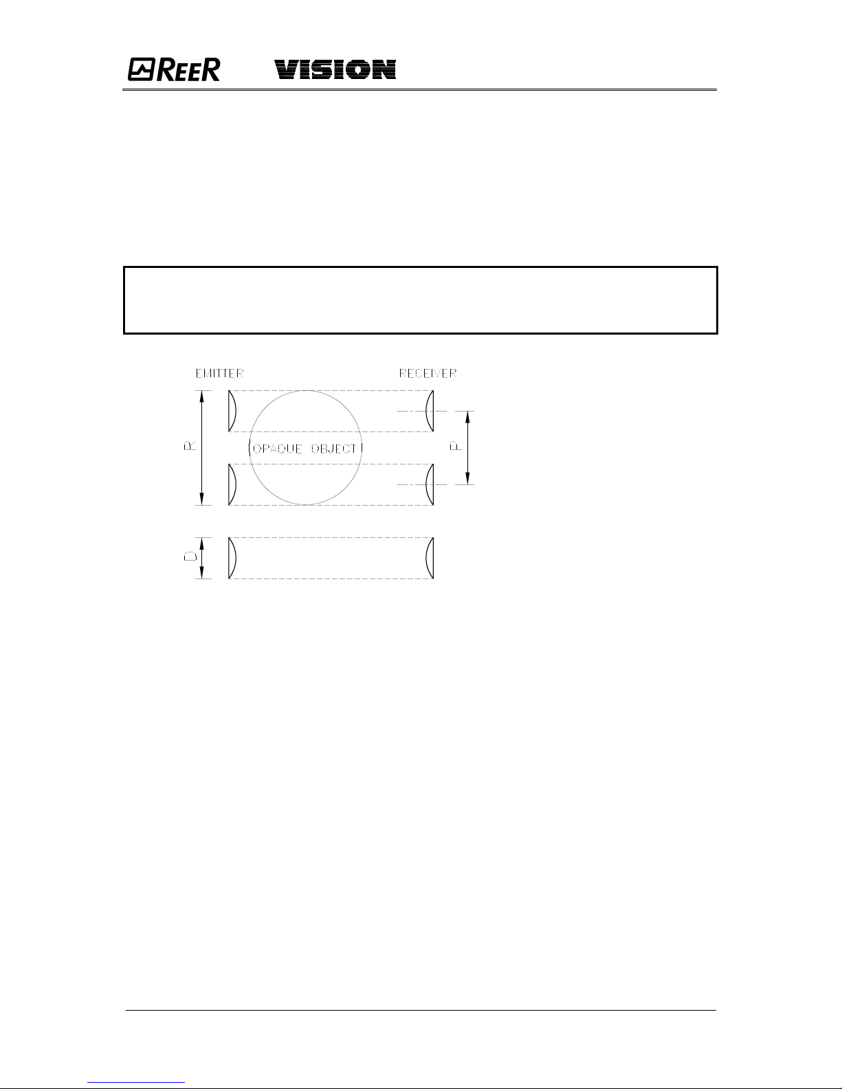
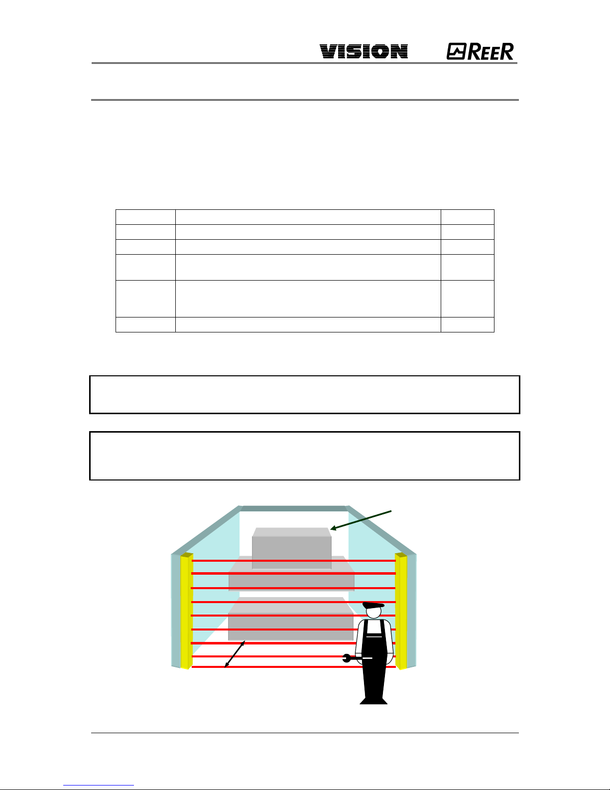
The resolution is the minimum dimensions that an object must have so that, on
crossing the protected area, it will certainly intercept at least one of the optical
beams generated by the barrier (Figure 1).
Figure 1
The resolution is constant irrespectively of work conditions, as it only depends on the
geometric characteristics of the lenses and the distance between the centres of two adjacent
lenses.
The height of the protected area is the height that is actually protected by the safety
barrier. If the latter is placed horizontally, this value refers to the depth of the protected area.
The working range is the maximum operative distance that can exist between the Emitter
and the Receiver.
VISION is available with the following resolutions:
– 20 mm (protected height from 150 mm to 1800 mm)
PROTECTION OF FINGERS
– 30 mm (protected height from 150 mm to 1800 mm)
PROTECTION OF HANDS
– 40 mm (protected height from 300 mm to 1800 mm)
PROTECTION OF HANDS
– 50 mm and 90 mm (protected height from 300 mm to 1800 mm)
PROTECTION OF ARMS AND LEGS
ADMIRAL is available also in the Multibeam configuration with the following lens pitch:
– 500mm (2 beams), 400mm (3 beams), 300mm (4 beams).
PROTECTION OF BODY
P = Pitch between two lenses
D = Diameter of one lens
Page 4
8540488 • 21/03/2016 • Rev.13 5
INSTALLATION
Before installing the VISION safety system, make sure that:
The safety system is only used as a stopping device and not as a machine control
device.
The machine control can be actuated electrically.
All dangerous machine movements can be interrupted immediately. In particular, the
machine stopping times must be known and, if necessary, measured.
The machine does not generate dangerous situations due to materials projecting or
falling from overhead; if that is not the case, additional mechanical guards must be
installed.
The minimum dimensions of the object that must be intercepted are greater than or
equal to the resolution of the specific model.
Knowledge of the shape and dimensions of the dangerous area enables the width and height
of the relative access area to be calculated.
Compare these dimensions with the maximum working range and the height of the
protected area in relation to the specific model.
The general instructions set out below must be taken into consideration before placing the
safety device in position.
Make sure that the temperature of the environment in which the system is to be
installed is compatible with the temperature parameters contained in the technical
data sheet.
Do not install the Emitter and Receiver close to bright or high-intensity flashing light
sources.
Certain environmental conditions may affect the monitoring capacity of the
photoelectric devices. In order to assure correct operation of equipment in places
that may be subject to fog, rain, smoke or dust, the appropriate correction factors Cf
should be applied to the maximum working range values. In these cases:
where Pu and Pm are, respectively, the working and maximum range in meters.
Pu = Pm x Cf
Page 5
6 8540488 • 21/03/2016 • Rev.13
The recommended Cf factors are shown in the table below:
ENVIRONMENTAL CONDITION
CORRECTION FACTOR Cf
Fog
0.25
Steam
0.50
Dust
0.50
Dense fumes
0.25
If the device is installed in places that are subject to sudden changes in temperature,
the appropriate precautions must be taken in order to prevent the formation of
condensation on the lenses, which could have an adverse effect on monitoring.
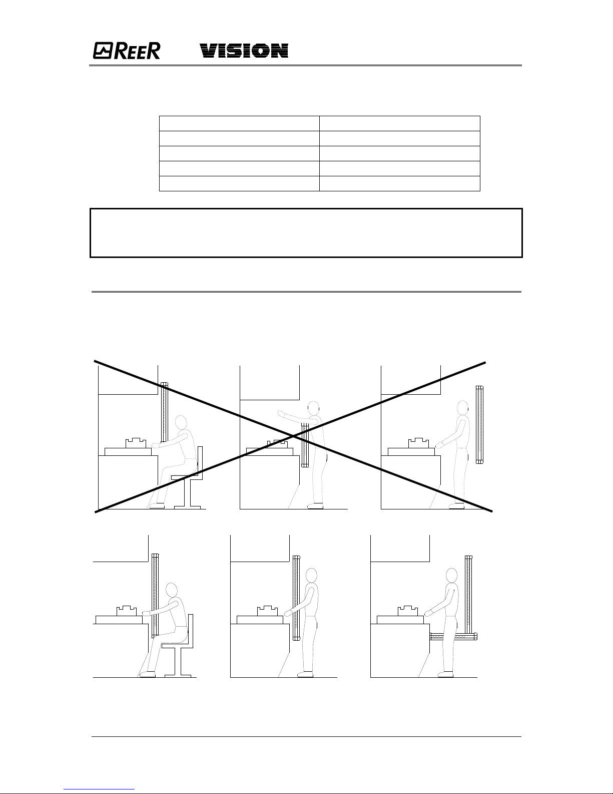
POSITION
The position of the VE Emitter and the VR Receiver must prevent access to the danger zone
from above, below and from the sides, unless at least one of the optical beams has been
intercepted. Some useful information regarding the correct position of the barrier is shown in
the figure below.
Incorrect positioning of barrier
Correct positioning of barrier
Figure 2
Page 6
8540488 • 21/03/2016 • Rev.13 7
SAFETY DISTANCE CALCULATION
The barrier must be installed at a distance that is greater than or equal to the minimum
safety distance S, so that a dangerous point can only be reached after all hazardous
machine movements have stopped (Figure 3).
According to European standard EN999, the minimum safety distance S must be calculated
using the following formula:
S = K (t1 + t2+ t3) + C
where:
S
minimum safety distance
mm K approach speed of object to the dangerous area
mm/sec
t1
response time of the safety barrier in seconds
sec
t2
response time of the safety interface in seconds
(e.g. PLC or safety module*)
sec
t3
machine response time, in seconds, meaning the time
required for the machine to interrupt the dangerous movement
following transmission of the stop signal
sec
c
additional distance
mm
* t
2
AD SR1 = 20 msec (refer to the technical manual of each single safety module, if different
from AD SR1).
The non-observance of the correct safety distance reduces or cancels the protective
action of the light curtain.
If the position of the barrier does not prevent the operator from having access to the
dangerous area without being detected, additional mechanical guards must be
installed to complete the system.
“S”=Safety distance
Figure 3
HAZARDOUS
MACHINE
S
Page 7

8 8540488 • 21/03/2016 • Rev.13
VERTICAL POSITION OF THE BARRIER
20 mm resolution models.
These models are suitable for the protection of
fingers.
30 mm and 40 mm resolution models.
These models are suitable for the protection of
hands.
The minimum safety distance S is calculated
according to the following formula:
S = 2000(t1 + t2+ t3) + 8(D-14)
(D=resolution)
This formula is valid for distances S between 100
and 500 mm. If this formula results in S being
greater than 500 mm, the distance can be reduced
to a minimum of 500 mm by means of the following
formula:
S = 1600(t1 + t2+ t3)+ 8(D-14)
If, due to the specific configuration of the machine,
the dangerous area can be accessed from above,
the highest beam of the barrier must be at a height
H of at least 1800 mm from the base G of the
machine.
Figure 4
50 mm and 90 mm resolution models.
These models are suitable for the protection of
arms or legs and must not be used to protect
fingers or hands.
The minimum safety distance S is calculated
according to the following formula:
S = 1600(t1 + t2+ t3) + 850
The height H of the highest beam from the
base G must never be less than 900 mm,
while the height of the lowest beam P
must never be more than 300 mm.
Figure 5
safety barrier
point of
danger
direction
of
approach
reference plane
safety barrier
point of
danger
direction
of
approach
reference plane
Page 8

8540488 • 21/03/2016 • Rev.13 9
Multibeam Models.
These models are suitable for the protection of
the entire body and must not be used to protect
arms or legs.
The minimum safety distance S is calculated
according to the following formula:
S = 1600 (t1 + t2+ t3) + 850
The reccomended height H from the base
(G) must be the following:
Figure 6
MODEL
BEAMS
Reccomended Height H (mm)
V2BL / V2BH
V3BL / V3BH
V4BL / V4BH
2
3
4
400 – 900
300 – 700 – 1100
300 – 600 – 900 - 1200
HORIZONTAL POSITION OF THE BARRIER
When the object’s direction of approach is parallel to
the floor of the protected area, the barrier must be
installed so that the distance between the outer limit
of the dangerous area and the most external optical
beam is greater than or equal to the minimum safety
distance S calculated as follows:
S = 1600(t1 + t2+ t3) + 1200 – 0.4H
where H is the height of the protected surface from
the base of the machine;
H = 15(D-50)
(D=resolution)
In this case, H must always be less than 1 meter.
In any case the following condition must be
respected :
1200 – 0.4H 850
Figure 7
safety barrier
point of
danger
direction
of approach
reference plane
safety
barrier
point of
danger
direction
of
approach
reference plane
Page 9

10 8540488 • 21/03/2016 • Rev.13
ELECTRICAL CONNECTIONS
WARNINGS
Before making the electrical connections, make sure that the supply voltage complies with
that specified in the technical data sheet.
Emitter and Receiver units must be supplied with 24Vdc±20% power.
The external power supply must comply with the standard EN 60204-1.
The electrical connections must be made according to the diagrams in this manual. In
particular, do not connect other devices to the connectors of the Emitter and Receiver.
To guarantee reliability of operation, when using a diode jumper supply unit, its output
capacity must be at least 2000µF for each absorbed A.
Page 10

8540488 • 21/03/2016 • Rev.13 11
Connector pins
Figure 8
EMITTER
NUMBER
COLOR
NAME
MEANING
1
Brown
24 VDC
Power supply (positive)
2
White
TEST
- Operation without TEST (+24VDC)
- TEST control (Transition +24VDC -> 0VDC
or open circuit)
3
Blue
0 VDC
Power supply (negative)
4
Black
N.C.
N.C.
5
Grey
PE
Ground connection
Table 1
If the TEST function is not required by the application, connect pin 2 of the emitter
to +24Vdc.
RECEIVER
NUMBER
COLOR
NAME
MEANING
1
Brown
24 VDC
Power supply (positive)
2
White
OSSD1
Static output No. 1 (PNP active high)
3
Blue
0 VDC
Power supply (negative)
4
Black
OSSD2
Static output No. 2 (PNP active high)
5
Grey
PE
Ground connection
Table 2
EMITTER RECEIVER
Page 11

12 8540488 • 21/03/2016 • Rev.13
Example of connection of the VISION barrier to the ReeR
AD SR1 safety module (with external contactors K1/K2)
+
+
-
Figure 9
Page 12

8540488 • 21/03/2016 • Rev.13 13
Example of connection of the VISION barrier to the ReeR
AD SR1 safety module (with internal contactors in series)
+
+
-
Figure 10
In this configuration the test is compulsory (with frequency determined by
risk analysis).
Page 13

14 8540488 • 21/03/2016 • Rev.13
Examples of connection of the VISION barrier
Figure 11
Page 14

8540488 • 21/03/2016 • Rev.13 15
Warnings regarding the connection cables
For connections over 50 m long, use cables with a cross-section area of 1 mm2.
The power supply to the barrier should be kept separate from that to other electric power
equipment (electric motors, inverters, frequency converters) or other sources of disturbance.
Connect the Emitter and the Receiver to the ground outlet.
The connection cables must follow a different route to that of the other power cables.
MULTIPLE SYSTEMS
When more than one VISION system is used, precautions must be taken to avoid optical
interference between them: install units so that the beam emitted by the Emitter of one
system can only be received by the relative Receiver.
Figure 12 illustrates some examples of correct positioning when two photoelectric systems
are installed. Incorrect positioning could generate interference, and may result in
malfunctioning.
Figure 12
If it is possible (depending on the application), we suggest to utilize the models with a
working range of 6m.
DISTANCE BETWEEN REFLECTING SURFACES
The presence of reflecting surfaces in proximity of the photoelectric barrier may generate
spurious reflections that prevent monitoring. With reference to Figure 13, object A is not
detected because surface S reflects the beam and closes the optical path between the
Emitter and Receiver.
A minimum distance d must therefore be maintained between any reflecting surfaces and
the protected area. The minimum distance d must be calculated according to the distance l
between the Emitter and the Receiver.
Figure 13
Systems installed alongside each other: A
Installation of two adjacent Emitters
Overlapping systems: B
L-shaped installation: C
Crossed positioning of Emitters and receivers
Page 15

16 8540488 • 21/03/2016 • Rev.13
Figure 14 illustrates the values for the minimum distance d that must be maintained when the
distance l between the Emitter and Receiver is changed.
Figure 14
After installing the system, check whether any reflecting surfaces intercept the beams, first in
the centre and then close to the Emitter and Receiver.
During these operations, the red LED on the Receiver should never, for any reason,
switch off.
Page 16

8540488 • 21/03/2016 • Rev.13 17
USE OF DEFLECTION MIRRORS
In order to protect or control areas that can be accessed from more than one side, in addition
to the Emitter and Receiver, one or more deflection mirrors can be installed.
These mirrors enable the optical beams generated by the Emitter to be deviated on one or
more sides.
If the beams emitted by the Emitter must be deviated by 90°, the perpendicular to the
surface of the mirror must form an angle of 45° with the direction of the beams.
The following figure illustrates an application in which two deviation mirrors are used to
provide a U-shaped protection.
Figure 15
The following rules should be taken into consideration when using deviation mirrors:
Place the mirrors so as to ensure compliance with the minimum safety distance S
(Figure 15) on each side from which the danger zone can be accessed.
The working distance (range) is given by the sum of the lengths of all the sides
that give access to the protected area. (Remember that for each mirror used
the maximum working range between the Emitter and the Receiver is
reduced by 15%).
During installation, take great care to avoid twisting along the longitudinal axis of
the mirror.
Make sure, by standing near to and on the axis of the Receiver, that the entire
outline of the Emitter is visible on the first mirror.
The use of more than three deviation mirrors is not recommended.
Page 17

18 8540488 • 21/03/2016 • Rev.13
MECHANICAL ASSEMBLY AND OPTIC ALIGNMENT
The Emitter and the Receiver must be assembled opposite each other (at a distance
specified in the technical data sheet). Use the fastening brackets and inserts supplied with
the system to place the Emitter and the Receiver so that these are aligned and parallel to
each other and with the connectors facing the same way.
Depending on the dimensions and the shape of the support on which they are to be installed,
the Emitter and Receiver must be assembled with the fastening inserts at the back, or else
by fitting these in the side groove (Figure 16).
Perfect alignment of the Emitter and Receiver is essential in order to assure correct barrier
operation. The indicator LEDs on the Emitter and Receiver facilitate this operation.
Figure 16
Position the optical axis of the first and last beam of the Emitter on the same
axis as that of the corresponding beams on the Receiver.
Move the Emitter in order to find the area within which the green LED on the
Receiver stays on, then position the first beam of the Emitter (the one close to
the indicator LEDs) in the centre of this area.
Using this beam as a pivot, effect small sideways movements of the opposite
end to move to the protected area clear condition. The green LED on the
Receiver will indicate this condition.
Lock the Emitter and Receiver in place.
During these operations it may be useful to check the yellow weak signal LED on the
Receiver. Upon completion of alignment, this LED must be off.
If the Emitter and the Receiver are assembled in areas that are subject to strong vibrations,
the use of vibration-damping supports is recommended, in order to prevent circuit
malfunctions.
 Loading...