

Page 1

CONTENTSCONTENTS
PHOTOELECTRIC BARRIER
ULISSE UNC
73/23/CEE
89/336/CEE
INSTALLATION, USE AND MAINTENANCE
WARNINGS.............................................................................................................................. 2
GENERAL................................................................................................................................. 3
OPERATION............................................................................................................................. 3
DIMENSIONS........................................................................................................................... 4
INDICATORS............................................................................................................................ 5
TECHNICAL DATA.................................................................................................................... 6
INSTALLATION......................................................................................................................... 7
SAFETY DISTANCE AND POSITIONING................................................................................... 8
Single beam protection................................................................................................ 9
Double beam protection.............................................................................................. 9
Distance from reflecting surfaces................................................................................ 10
Multiple systems........................................................................................................ 10
Electrical connections................................................................................................ 11
Mechanical installation and optical alignment ............................................................17
CHECKS AND MAINTENANCE. ............................................................................................. 17
OPERATING FAULTS..............................................................................................................17
IDENTIFICATION LABELS ......................................................................................................18
ORDERING CODE AND SPARE PARTS...................................................................................18
Ordering codes......................................................................................................... 18
Spare parts. .............................................................................................................. 18
WARRANTY ............................................................................................................................ 19
1
Page 2

CAUTION
ULISSE UNC series photocells
WITHOUT THE CONTROL UNITSWITHOUT THE CONTROL UNITS
AU S3, AU S-TWIN or AU S3M2AU S3, AU S-TWIN or AU S3M2
cannot be used as safety devices for the protection of people exposed to
hazardous machines or systems.
Accordingly, REER will not be liable for any consequences arising from the
use of its ULISSE photocells without the relative control units, as this use
does not meet the requirements of EC machine directive 89/392.
WARNINGSWARNINGS
The ULISSE UNC safety system is composed of one or two pairs of photocells connected
either to the standard control unit (AU S3) or to the unit with built-in muting function
(AU S3M2); the system can be composed of one, two, three or four pairs of photocells
connected to the control unit AU S-TWIN.
To understand the operation of these devices we recommend reading a few sections of the
relative installation manuals; in particular:
• Manual code 8540399 - "AU S-TWIN":
– Operating modes
– Configuration of the unit
– Status of contacts
– Indicator lights
– Specifications
• Manual code 8540404 - "ARGOLUX series AS":
– Test function and control unit status
– Start up test
– Operating diagram
– Status of contacts
– Indicators (Control unit)
– Technical data (Control unit)
– Electrical connections
• Manual code 8540408 - "MUTING, AU S3M2 control unit":
– General
– Operating diagram
– Status of contacts
– Indicators
– Technical data
– Electrical connections
2
Page 3

GENERALGENERAL
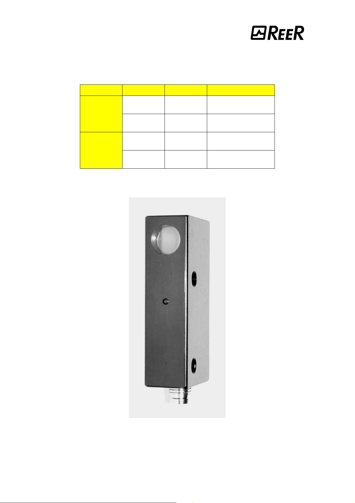
ULISSE UNC is a barrier type photocell consisting of a separate emitter and a receiver.
Whether connected to the control units, AU S3, AU S-TWIN, or to the control unit with
built-in muting function, AU S3M2, ULISSE UNC represents a type 2 safety system with one,
two, three or four (AU S-TWIN) beams, suitable for the protection against accidents of
people exposed to hazards on dangerous machinery. The metal container and the glass
lenses make the product extremely sturdy and immune to the electrostatic attraction of dust,
i.e., ideally suited for use in the textile processing plants.
The switching of the output relays of the control unit upon the interception of the beam stops
the movement of machine tools with mechanical moving parts, such as, for instance:
• Looms;
• Assembly lines;
• Automated industrial warehousing systems;
• Robotised areas;
• Handling, palletising/de-palletising systems.
The protection function will not work if:The protection function will not work if:
The control part of the machine cannot be controlled electrically or is unable toThe control part of the machine cannot be controlled electrically or is unable to
F
stop the hazardous movement at once and at any time in the course of thestop the hazardous movement at once and at any time in the course of the
processingcycle.processingcycle.
The hazard condition is associated with the risk of objects falling from above orThe hazard condition is associated with the risk of objects falling from above or
F
ejected from the machine.ejected from the machine.
For applications in the food processing industry, contact the manufacturer toFor applications in the food processing industry, contact the manufacturer to
F
assess the compatibility between the photocell material and the chemical agentsassess the compatibility between the photocell material and the chemical agents
employed.employed.
For questions affecting safety, if necessary, consult the authorities responsibleFor questions affecting safety, if necessary, consult the authorities responsible
F
for safety-related matters in your country, or the cognisant manufacturers'for safety-related matters in your country, or the cognisant manufacturers'
association.association.
OPERATIONOPERATION
The ULISSE UNC safety system may consist of one two, three or four emitter/receiver pairs
connected to a control unit. This system is able to detect the passage of a person’s entire
body and cannot be used for the protection of arms and hands.
Whenever the optical path of the infrared beam linking the emitter to the receiver is totally
interrupted, the receiver cuts off the output signal. Upon recognising this condition, the
control unit immediately de-energises its outputs thereby preventing the coming into being of
a hazard condition.
When the beam is released, the system restart depends on the positive outcome of the test
function. The test is conducted as follows:
• the control unit turns off the emitter;
• the receiver detects the interruption of the beam and cuts off the output signal;
• the control unit checks the adequacy of the reaction time of the receiver, the outputs of
the latter and the external relays, if any are used.
This test is controlled externally, by pressing a special test button.
3
Page 4

DIMENSIONSDIMENSIONS
Emitter and receiverEmitter and receiver
4
Page 5
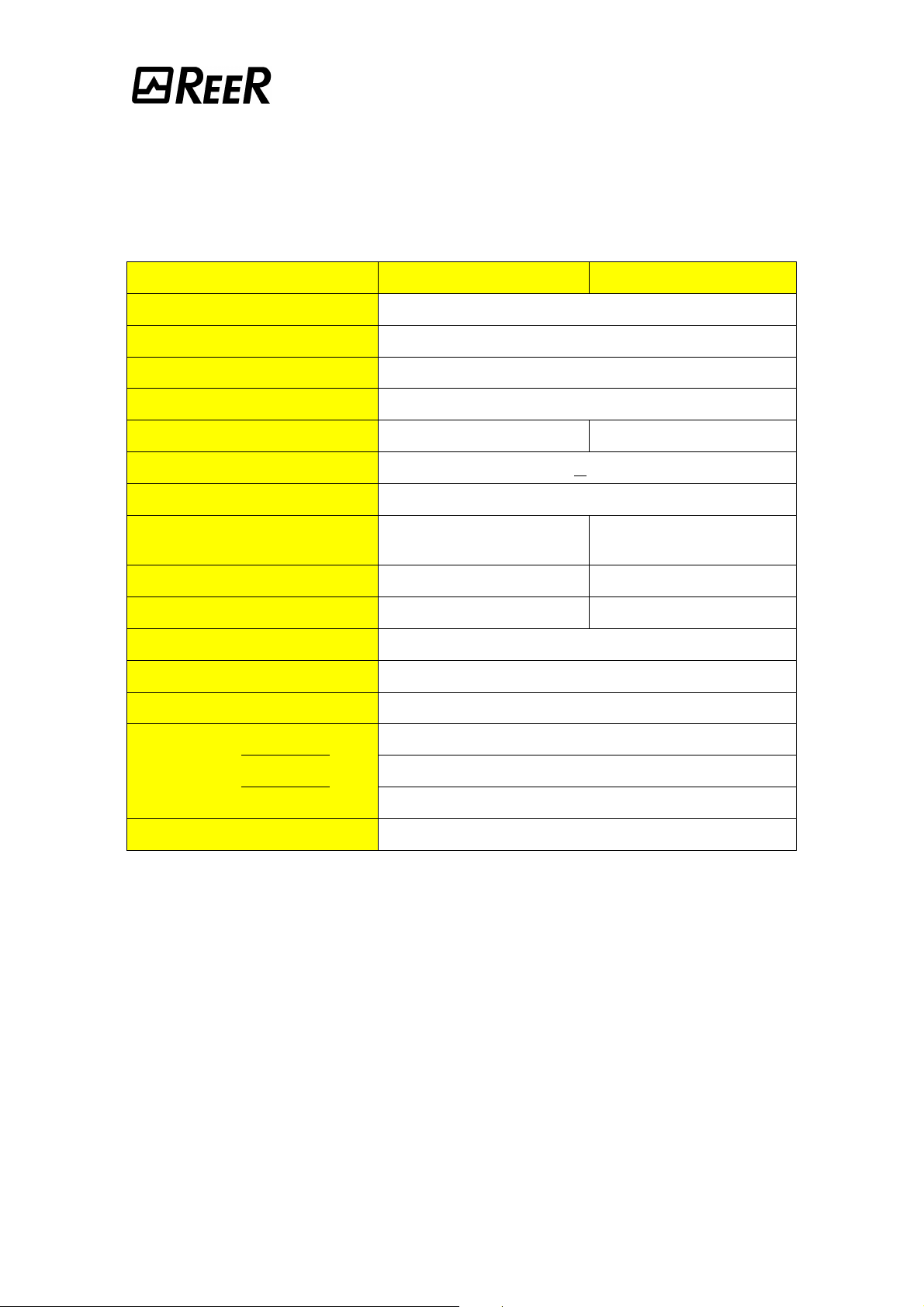
INDICATORSINDICATORS
COLOURCOLOUR STATESTATE INDICATIONINDICATION
EMITTER
RECEIVER
Yellow ON
Yellow OFF
Green ON
Green OFF
Beam
emitted
Test function
or no beam
Controlled
area is free
Controlled
area is obstructed
Figure Figure 11
5
Page 6
TECHNICAL DATATECHNICAL DATA
MODELMODEL UNCE-EMITTERUNCE-EMITTER UNCR-RECEIVERUNCR-RECEIVER
Scanning range m 0,8 ÷ 6
Minimum detectable item mm 8
Immunity to ambient light lx > 10.000 (solar)
Emission angle ± 4°
Emission wavelenght nm 880 (modulated infrared)
Response time ms < 8
Power supply Vdc 24 ± 20%
Power comsumption
at 24 Vdc
Output NPN 100 mA max Light on
Test input NPN active low
Connections M8 Connector
Operating temperature °C 0 ÷ 55 (with no condensate and no frosting)
Protection degree IP 65
Width 15
Depth mm 25Dimensions
Height 63
Weight g 40
W 0,7 0,4
6
Page 7

INSTALLATIONINSTALLATION
The ULISSE UNC photocell used in conjunction with control unit AU S3, AU S-TWIN or
AU S3M2 represents an electro-sensitive type 2 protection system.
As provided for in the standard IEC 61496-1/2 (formerly prEN50100) in a type 2 safety
device, faults or malfunctioning must be detected during the test stage.
In a type 2 safety device, the test is mandatory, at least at power on of the machine. If the
test is successful, the output relays are then energized.
Before installing the ULISSE UNC safety system, make sure that:Before installing the ULISSE UNC safety system, make sure that:
The hazard level of the machine is compatible with the use of type 2 electro-The hazard level of the machine is compatible with the use of type 2 electro-
F
sensitive safety devices.sensitive safety devices.
The machine/processing cycle are compatible with the use of a type 2 electro-The machine/processing cycle are compatible with the use of a type 2 electro-
F
sensitive safety system.sensitive safety system.
The processing cycle or any dangerous movement of the machine parts can beThe processing cycle or any dangerous movement of the machine parts can be
F
started only by working on a control. In particular, the safety system must bestarted only by working on a control. In particular, the safety system must be
used solely as a stopping device, not as a machine control unit.used solely as a stopping device, not as a machine control unit.
The test control is outside the hazardous area, at a place offering a clear viewThe test control is outside the hazardous area, at a place offering a clear view
F
of the working area.of the working area.
The machine can be electrically controlled.The machine can be electrically controlled.
F
Any hazardous movement of the machine can be stopped at once. In particular,Any hazardous movement of the machine can be stopped at once. In particular,
F
it is necessary to ascertain the machine stopping time, by measuring it, ifit is necessary to ascertain the machine stopping time, by measuring it, if
necessary.necessary.
The machine will not give rise to hazardous conditions due to parts beingThe machine will not give rise to hazardous conditions due to parts being
F
ejected or falling from above; otherwise, it becomes necessary to fit additionalejected or falling from above; otherwise, it becomes necessary to fit additional
protective devices of a mechanical type.protective devices of a mechanical type.
Before positioning the system, take into consideration the following general provisions:
• Make sure that the temperatures of the environments in which the system is installed are
compatible with the temperature operating parameters given in the technical data table
(page 5).
• Do not place the emitter or the receiver in the proximity of high-intensity or blinking
light sources.
• Place the control unit in an environment whose degree of protection is at least IP54.
Special environmental conditions may affect the sensing efficiency of the photoelectric
device.
If the system is installed in places subject to sudden temperature variations, it is
indispensable to adopt the customary measures to prevent the formation of condensate on
the lenses, as this might impair their detection capabilities.
7
Page 8

SAFETY DISTANCE AND POSITIONINGSAFETY DISTANCE AND POSITIONING
The photocell must be installed at a distance greater than or equal to the minimum safety
distance, S, so that no hazardous point can be reached until the hazardous action of the
machine has stopped (fig. 2).
Figure Figure 22
With reference to the proposed European standard prEN999, the minimum safety distance,
S, must be calculated through the following formula:
S = K(tb + tu + t1 ) + C
where:
SS is the minimum safety distance expressed in mm.
KK is the speed of approach of the body to the hazardous zone in mm/sec.
tb+ tutb+ tu is the total reaction time of the sensor plus the control unit (≤ 31ms).
t1t1 is the reaction time of the machine in seconds, i.e., the time it takes for the machine to
stop the hazardous action from the time the control unit transmits the stop signal through
the opening of its output circuit.
CC is an additional distance in mm
8
Page 9

Single beam protection.
If the risk analysis permits the use of a single beam to detect the presence of a person
intercepting the beam with his/her body as he/she approaches the hazardous area in a
standing position (fig. 3), determine the minimum safety distance with the aid of the
following formula:
S = 1600(tb + tu + t1) + 1200
In this case we recommend arranging the equipment so that the beam will run parallel to the
reference plane, G, at a height H=750mm (fig. 3).
When using a single beam system, it is necessary to examine closely the risk of people
intruding into the hazardous area without intercepting the beam.
Figure Figure 33
Figure Figure 44
Double beam protection.
When using two ULISSE UNC photocells one on top of the other so that the beams are
arranged one on top of the other, it becomes possible to set up a double beam
protective system.
In these conditions, the minimum safety distance must be determined through the following
formula:
S = 1600(tb + tu + t1) + 850
The distances, H, of the beams from the reference plane G, are 400mm and 900mm,
respectively (fig. 4).
9
Page 10

Distance from reflecting surfaces.
Reflecting surfaces located next to the photocell(s) may cause spurious reflections that would
close the optical path between the emitter and the receiver and inhibit the system's detection
capability (fig. 5).
Figure Figure 55
Having completed the installation, check for the presence of reflecting surfaces which might
intercept the beam, first in the centre and then in the proximity of the emitter and the
receiver. If any object is intercepted, the green led located on the receiver (fig. 1) must
never light up.
Multiple systems.
When using 2, 3 or 4 pairs of ULISSE UNC photocells arranged next to or on top of each
other in order to prevent them from mutually interfering it is necessary to arrange the
elements so that the beam emitted by one system is received only by the respective
receiver (fig. 6).
The emitter of one pair must not result in front of the receiver of the other pairs.The emitter of one pair must not result in front of the receiver of the other pairs.
F
Systems arranged side by side: (A)Systems arranged side by side: (A)
The two emitters are adjacent.
Systems one on top of the other: (B)Systems one on top of the other: (B)
Emitters and receivers in cross position.
10
Figure Figure 66
Page 11

Electrical connections
For the electrical connections, ULISSE UNC photocells are fitted with a 3 pin male connector
(fig. 7). It is possible to use 5 m cables equipped with M8 female connector, either straight
or at 90°, supplied on request.
• Make the connections according
to the diagrams given in pages
12, 13, 14, 15 and 16.
• It is important to take into account
the following indications:
• Before making the connections,
make sure that the mains voltage
value corresponds to the rating
given in the technical data.
Figure Figure 77
±20% power supply (e.g. through an isolating transformer conforming to EN 60742).
• Connector pin No. 3 is electrically connected to the metal case of the photocell. If the
photocell has to be linked to a metal part of the machine which is connected to the
ground, the return line of the 24 Vdc voltage distribution system has to be connected to
ground too. If this is not so, the photocell case must be insulated from the metal part of
the machine.
• For connections of over 50m in length, use cables with cross section of 1mm2.
• The power line for the barrier and the control unit should be separate from the lines
powering the other electrically operated devices (electric motors, inverters, frequency
variators) or other possible sources of noise.
• Connect the control unit to the ground socket.
• The cables linking the control unit and the photocell, the connection for the test
command and any connections relating to system control parts (e.g. self-test output)
must follow a different path with respect to the power cables.
• Photocells and control unit must
be supplied with PELV type 24Vdc
For a correct operation of the ULISSE UNC photoelectric system, we recommendFor a correct operation of the ULISSE UNC photoelectric system, we recommend
F
reading a few sections of the relative installation manuals; in particular:reading a few sections of the relative installation manuals; in particular:
• Code 8540399 - "AU S-TWIN":
– Operating modes
– Installation and electric connections
• Code 8540404 - "ARGOLUX series AS" Manual:
– Technical data of the output circuit
– Use of auxiliary contact elements K1 and K2
– The TEST control
• Code 8540408 - "MUTING, AU S3M2 safety unit" Manual:
– Technical data of output circuit
– Use of auxiliary contact elements K1 and K2
– The TEST control
– Muting sensors
– Technical data of external indicator system
11
Page 12

Connection with AU S3 unit.Connection with AU S3 unit.
Connection with AU S3 unit and with auxiliary external relays K1 and K2 control.Connection with AU S3 unit and with auxiliary external relays K1 and K2 control.
12
Page 13

Connection with AU S3M2 muting unit.Connection with AU S3M2 muting unit.
13
Page 14

Connection with AU S3M2 muting unitConnection with AU S3M2 muting unit
with auxiliary external relays K1 and K2 control.with auxiliary external relays K1 and K2 control.
14
WARNING: To connect the muting sensors, refer to manual code 8540408.
Page 15

Connection of two pairs of photocellsConnection of two pairs of photocells
with AU S3 unit or AU S3M2 muting unit.with AU S3 unit or AU S3M2 muting unit.
Connection with AU S-TWIN unit.Connection with AU S-TWIN unit.
15
Page 16

Connection of four pairs of photocells with AU S-TWINConnection of four pairs of photocells with AU S-TWIN
and with auxiliary external relays K1 and K2 control.and with auxiliary external relays K1 and K2 control.
16
Page 17

Mechanical installation and optical alignment
The emitter and the receiver must be installed one in front of the other at a distance not to
exceed the effective capacity of the equipment.
A perfect alignment between the emitter and the receiver is essential for the flawless
operation of this device. This operation is facilitated by the presence of a green indicator
LED on the receiver.
CHECKS AND MAINTENANCE.CHECKS AND MAINTENANCE.
The ULISSE UNC photocell must be used within the working parameters given in the
technical data. At the beginning of each work shift, or at power up, it is necessary to check
the functionality of the photocell through the following procedure: intercept the beam with a
cylinder shaped opaque object with a diameter of 8 mm to be placed at the centre of the
area between the emitter and the receiver, and then in the proximity of both, and make sure
that in each of these cases, the green led “free area light” on the receiver goes off, while at
the same time the control unit output is switched.
The ULISSE UNC photocell has no specific maintenance requirement; at all events, we
recommend cleaning the lenses of the emitter and the receiver at regular intervals, so as to
prevent an excessive quantity of dust from building up and hampering the optical beam
transmission and reception functions, as this may result in the failure of the equipment and
the machine connected to it.
Do not use abrasive or corrosive products, or solvents or alcohol which might damage the
parts to be cleaned.
OPERATING FAULTS.OPERATING FAULTS.
If any operating faults persist even if the system is turned off and on, check the conditions of
the electrical connections.
Furthermore, make sure that the emitter and the receiver are correctly aligned, and the
lenses are perfectly clean. If these measures are not sufficient to restore correct system
operation, send the equipment to our laboratories, complete with all its parts, specifying
clearly:
• part number;
• date of installation;
• hours of operation;
• type of installation;
• fault observed.
17
Page 18

IDENTIFICATION LABELSIDENTIFICATION LABELS
ORDERING CODE AND SPARE PARTSORDERING CODE AND SPARE PARTS
Ordering codes.
S/N field codification:
S/N
Year of production Serial number
Week of production
ITEMITEM CODECODE
Emitter+ Receiver UNCE + UNCR 1200302
Emitter UNCE 1400302
Receiver UNCR 1500302
Spare parts.
ITEMITEM CODECODE
Female connector M8 90° (5m cable) 1200216
Female connector M8 (5m cable) 1200217
Female connector M8 (15m cable) 1200219
Female connector M8 90° (15m cable) 1200221
18
Page 19

WARRANTYWARRANTY
For each newly produced ULISSE UNC, in regular utilisation conditions, REER S.p.A.
warranties the absence of defects in terms of materials and construction for a period of 12
(twelve) months.
During said period, REER S.p.A. undertakes to eliminate any product flaw by repairing or
replacing the defective parts, at no cost to the buyer where both the materials and labour
are concerned.
At any rate, REER S.p.A. reserves the right to replace a defective apparatus in its entirety, with
another of identical or similar characteristics, instead of repairing individual defective parts,
at its discretion.
The validity of this warranty is subject to the following conditions:
• The fault is notified to REER S.p.A. within twelve months of the date of delivery of
the product.
• The parts making up the equipment are undamaged.
• The REER part number is clearly legible.
• The fault or malfunctioning has not been directly originated by any of the following
causes:
– Utilisation for purposes other than those the equipment is intended for;
– Failure to comply with utilisation instructions;
– Negligence, human errors, inadequate maintenance;
– Repairs, changes, adaptations not performed by REER personnel, tampering, etc.;
– Accidents or impact (even those due to transport or force majeure);
– Other causes independent of REER S.p.A.
Repairs shall be performed at the laboratories of REER S.p.A., where the material must be
delivered or shipped to: transport expenses and the risks of damage or loss of materials
during shipment shall be borne by the user.
Replaced products and components become the property of REER S.p.A.
REER S.p.A. does not recognise any warranties or rights other than those expressly described
above; in no circumstances shall the user be entitled to seek damage for expenses incurred,
down-time or any other events associated with faults of the product or parts thereof.
The data and instructions contained in this manual may change as ULISSE
products are developed.
Since a good knowledge of this manual is essential for correct use and
installation, please always refer to the version contained in the product's
packaging case.
19
 Loading...