

Page 1

Installation,
use and maintenance
(Copy of the original instructions)
Type 4 barrier for Access Control
with Muting functions integrated
Page 2

Introduction
SUMMARY
INTRODUCTION ...........................................................................................................................5
PURPOSE OF THIS DOCUMENT ...................................................................................................................... 5
PRODUCT DESCRIPTION ................................................................................................................................. 5
CONTENT OF THE PACKAGE ........................................................................................................................... 5
GLOSSARY ........................................................................................................................................................... 6
DISPOSAL OF MATERIALS ............................................................................................................................... 6
SAFETY ........................................................................................................................................7
SIMBOLOGY ......................................................................................................................................................... 7
PRECAUTIONS .................................................................................................................................................... 7
CAUTIONS BEFORE INSTALLATION ................................................................................................................ 8
LIST OF APPLICABLE STANDARDS ................................................................................................................. 9
EC DECLARATION OF CONFORMITY ............................................................................................................ 10
SYSTEM ARCHITECTURE ........................................................................................................11
POSSIBLE CONFIGURATIONS (VIA OPTIONAL ACCESSORIES) ............................................................. 12
THE MUTING FUNCTION ...........................................................................................................15
A) 2 INTEGRATED CROSS MUTING SENSORS, ONLY FOR PALLET OUTPUTS (LX) ............................. 16
B) 2 INTEGRATED PARALLEL MUTING SENSORS, ONLY FOR PALLET OUTPUTS (L2) ........................ 17
C) 2 INTEGRATED CROSS MUTING SENSORS, FOR BI-DIRECTIONAL GATES (TX) ............................ 18
D) 4 INTEGRATED PARALLEL MUTING SENSORS, FOR BI-DIRECTIONAL GATES (T4) ....................... 19
Concurrent ..............................................................................................................................................................19
E) 2 EXTERNAL CROSS INTEGRATED MUTING SENSORS, FOR BI-DIRECTIONAL GATES (TX).
F) 4 EXTERNAL PARALLEL MUTING SENSORS, FOR BI-DIRECTIONAL GATES (T4). .......................... 21
Concurrent ..............................................................................................................................................................21
PARTIAL MUTING .............................................................................................................................................. 22
Partial Muting with Enable .......................................................................................................................................22
Partial Muting with Disable ......................................................................................................................................22
MUTING OVERRIDE .......................................................................................................................................... 23
Override with spring return key ................................................................................................................................23
Override with pushbutton .........................................................................................................................................23
INSTALLATION ...........................................................................................................................24
CALCULATION OF THE SAFETY DISTANCE ................................................................................................. 24
GENERAL FORMULA FOR CALCULATING THE SAFETY DISTANCE ........................................................ 24
MODELS WITH RESOLUTION 30 MM – 40 MM .............................................................................................. 25
MODELS WITH 2/3/4 BEAMS............................................................................................................................ 25
MULTIPLE SYSTEMS ........................................................................................................................................ 27
USE OF DEFLECTING MIRRORS ................................................................................................................... 28
DISTANCE FROM REFLECTING SURFACES ................................................................................................ 29
MECHANICAL ASSEMBLY AND OPTICAL ALIGNMENT ............................................................................... 30
SM - SMO MODELS ELECTRICAL CONNECTIONS ................................................................31
PRECAUTIONS ................................................................................................................................................. 31
WARNINGS ON CONNECTION CABLES ........................................................................................................ 31
EMITTER CONNECTIONS ............................................................................................................................... 31
RECEIVER CONNECTIONS ............................................................................................................................. 33
TEST FUNCTION ............................................................................................................................................... 34
SELECTION OF OPERATING MODES ............................................................................................................ 35
EDM ..................................................................................................................................................................... 36
OVERRIDE .......................................................................................................................................................... 37
OVERRIDE WITH KEY WITH SPRING RETURN KEY ................................................................................... 37
OVERRIDE WITH PUSHBUTTON ................................................................................................................... 37
RESTART (MANUAL OPERATION) .................................................................................................................. 38
AUTOMATIC OPERATION ................................................................................................................................ 38
MUTING ENABLE............................................................................................................................................... 39
8541150 - rev.1 - 10/07/2017
REER S.p.A. - 32 via Carcano - 10153 Torino Italia Internet: www.reer.it - e-mail: info@reer.it
Muting Enable active: correct Muting sequence ......................................................................................................39
20
2
Page 3

Introduction
APPENDIX A: SM - SMO MODELS WIRING SAMPLES ..........................................................40
SMP - SMPO MODELS ELECTRICAL CONNECTIONS ...........................................................44
PRECAUTIONS ...................................................................................................................................... 44
WARNINGS ON CONNECTION CABLES ............................................................................................ 44
EMITTER CONNECTIONS ............................................................................................................................... 44
RECEIVER CONNECTIONS ............................................................................................................................. 46
Available congurations. ..........................................................................................................................................46
TEST FUNCTION ............................................................................................................................................... 48
SELECTION OF OPERATING MODES ............................................................................................................ 49
EDM ..................................................................................................................................................................... 49
OVERRIDE (PC PROGRAMMING) ................................................................................................................... 50
OVERRIDE WITH SPRING RETURN KEY ...................................................................................................... 50
OVERRIDE WITH PUSHBUTTON ................................................................................................................... 50
RESTART (MANUAL OPERATION) .................................................................................................................. 51
AUTOMATIC OPERATION ................................................................................................................................ 51
MUTING ENABLE............................................................................................................................................... 52
Muting Enable active: correct Muting sequence ......................................................................................................52
MUTING ENABLE/DISABLE ............................................................................................................................. 52
Muting Enable/Disable active: Correct Muting sequence ........................................................................................52
PARTIAL MUTING .............................................................................................................................................. 53
1) Partial Muting with Enable ...................................................................................................................................53
2) Partial Muting with Disable ..................................................................................................................................53
APPENDIX B: SMP - SMPO MODELS WIRING SAMPLE ........................................................54
S MODELS ELECTRICAL CONNECTIONS ..............................................................................55
PRECAUTIONS ................................................................................................................................................. 55
WARNINGS ON CONNECTION CABLES ....................................................................................................... 55
TEST FUNCTION ............................................................................................................................................... 57
APPENDIX C: S MODELS WIRING SAMPLES .........................................................................57
LIGHT SIGNALS .........................................................................................................................58
EMITTER SIGNALS .......................................................................................................................................... 58
RECEIVER SIGNALS......................................................................................................................................... 59
RECEIVER SIGNALS (INTEGRATED LAMP) .................................................................................................. 60
FAULT DIAGNOSIS - EMITTER ........................................................................................................................ 61
FAULT DIAGNOSIS - RECEIVER ..................................................................................................................... 62
TECHNICAL SPECIFICATIONS .................................................................................................63
MECHANICAL DIMENSIONS .....................................................................................................66
CURTAIN DIMENSIONS .................................................................................................................................... 66
ACCESSORY DIMENSIONS ............................................................................................................................. 68
SOFTWARE SAFEGATE CONFIGURATOR ..............................................................................71
SOFWARE INSTALLATION ................................................................................................................... 71
HARDWARE characteristics requested by the PC for connection...........................................................................71
SOFTWARE characteristics requested by the PC for connection ...........................................................................71
How to install SAFEGATE CONFIGURATOR ..........................................................................................................71
CONFIGURATION PHASES.............................................................................................................................. 71
THE TOOLBAR ................................................................................................................................................... 72
GRAPHICAL INTERFACE ................................................................................................................................. 73
Level 1 password .....................................................................................................................................................73
Level 2 password .....................................................................................................................................................73
CONNECTION WITH SAFEGATE .................................................................................................................... 74
DOWNLOAD CONFIGURATION ...................................................................................................................... 74
CURTAIN PROGRAMMING .............................................................................................................................. 75
Level 2 password .....................................................................................................................................................75
8541150 - rev.1 - 10/07/2017
REER S.p.A. - 32 via Carcano - 10153 Torino Italia Internet: www.reer.it - e-mail: info@reer.it
3
Page 4

Introduction
CONFIGURATION VALIDATION AND LOADING ............................................................................................ 75
PRINT REPORT CONFIGURATION ................................................................................................................ 76
CONFIGURATION HISTORY ............................................................................................................................ 76
ERRORS DOWNLOAD ...................................................................................................................................... 76
SAFEGATE ACTIVATION .................................................................................................................................. 77
CURTAIN CONDITION MONITORING ............................................................................................................ 77
SETTING CURTAIN GENERAL PARAMETERS .............................................................................................. 77
SETTING MUTING PARAMETERS .................................................................................................................. 78
“Concurrent” Muting .................................................................................................................................................78
“Sequential” Muting ..................................................................................................................................................79
“L” Muting .................................................................................................................................................................80
“T” Muting ................................................................................................................................................................81
PARTIAL MUTING .............................................................................................................................................. 82
Partial Muting with Enable .......................................................................................................................................82
Partial Muting with Disable ......................................................................................................................................82
Partial Muting: MONITOR ........................................................................................................................................82
MUTING OVERRIDE .......................................................................................................................................... 83
Override with spring return key ...............................................................................................................................83
Impulse override ......................................................................................................................................................83
SAFEGATE DIAGNOSTIC - ERRORS ............................................................................................................. 84
CONTROLS, CARE AND MAINTENANCE ................................................................................85
PRE-ACTIVATION CHECKLIST ........................................................................................................................ 85
PERIODIC CONTROL ....................................................................................................................................... 85
CARE AND MAINTENANCE .............................................................................................................................. 86
WARRANTY ................................................................................................................................87
8541150 - rev.1 - 10/07/2017
REER S.p.A. - 32 via Carcano - 10153 Torino Italia Internet: www.reer.it - e-mail: info@reer.it
4
Page 5

Introduction
INTRODUCTION
Dear customer, REER congratulates you on purchasing this product.
Refer to this manual before using SAFEGATE; keep the CD-ROM and the Quick Installation Guide in a
place easy to be found in order to be able to refer to them when needed.
PURPOSE OF THIS DOCUMENT
This manual illustrates the operation of the programmable access curtain with Muting integrate SAFEGATE
functions. It shows specically:
¾ a general description of the SAFEGATE world;
¾ the characteristics of the muting function;
¾ the dierent types of muting and their application;
¾ the list of SAFEGATE models;
¾ the mechanical installation;
¾ the electrical connections;
¾ the mode of operation;
¾ the Muting, Override modes and their activation;
¾ SAFEGATE programming through dedicated software.
PRODUCT DESCRIPTION
The SAFEGATE light curtain is an optoelectronic multi-beam safety system belonging to the category of
Type 4 electro-sensitive devices (in accordance with EN 61496-1,2), equipped with the Muting function, for
the protection of persons exposed to dangerous machines or plants.
SAFEGATE ensures a perfect integration of the Muting sensors that are connected directly to the connectors
on the safety curtain.
In the hardware conguration models (SM and SMO) the Muting logic and the operating parameters are
fully dened by the connections of the main connector.
The SMPO programmable models retain all the features of SM and SMO models allowing also the
conguration of various parameters and additional features via the SCS software (SAFEGATE Conguration
Software).
The main features of SAFEGATE are as follows:
¾ Resolution: 30 and 40 mm – 2, 3 and 4 beams.
¾ Integration of the main safety functions, including self-monitoring of static outputs, EDM and Start/
Restart Interlock.
¾ Outline dimensions: 55 x 50 mm.
¾ Protected height: 300 to 2200 mm.
¾ Degree of protection: IP65 e IP67.
¾ Operating temperature: -30 ... +55 ° C (no condensation).
¾ Muting lamp and integrated curtain status indication (SMO/SMPO).
CONTENT OF THE PACKAGE
¾ SAFEGATE emitter and receiver
¾ CD-ROM (Containing conguration software and this Manual)
¾ Quick Installation Guide
¾ Mounting accessories bag
¾ Sealing caps for unused connectors
8541150 - rev.1 - 10/07/2017
REER S.p.A. - 32 via Carcano - 10153 Torino Italia Internet: www.reer.it - e-mail: info@reer.it
5
Page 6
Introduction
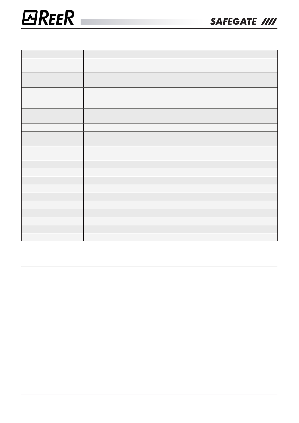
GLOSSARY
PROTECTED HEIGHT A measure that indicates the height controlled by the curtain.
SAFETY DISTANCE
EDM
MUTING
OVERRIDE
RANGE Maximum operating distance: between emitter and receiver
RESOLUTION
START/RESTART
INTERLOCK
RESPONSE TIME Time: between interruption of the gate and disabling of outputs
LX Muting Logic with 2 mono-directional cross-sensors
L2 Muting Logic with 2 mono-directional parallel sensors
TX Muting Logic with 2 bi-directional cross-sensors
T4 Muting Logic with 4 bi-directional parallel sensors
S Model without Muting
SM Model with Muting and Hardware conguration on main connector
SMO SM model with integrated Muting lamp
SMP Model with Muting Programmable with SCS software
SMPO SMP model with integrated Muting lamp
Minimum distance that must exist between the protected gate and the
dangerous area
External Device Monitoring: control of external contactors switching through
the feedback input.
Function of temporary suspension of the safety function: temporary exclusion
of the safety curtain, automatically and safely carried out based on the
machine cycle.
Forced activation of OSSD outputs: during the muting cycle for material
removal
Minimum detectable object size: to ensure the arrest of the dangerous
machine
Interlock function (manual reset required): when starting or restarting the
machine
DISPOSAL OF MATERIALS
Learn the regulations for collecting electrical and electronic products in force in the country where you want
to dispose of your product.
Observe local regulations for waste disposal and do not throw away old products with normal domestic
waste.
A proper disposal of non-usable products prevents potential negative consequences for the environment
and the population.
8541150 - rev.1 - 10/07/2017
REER S.p.A. - 32 via Carcano - 10153 Torino Italia Internet: www.reer.it - e-mail: info@reer.it
6
Page 7
Safety
SAFETY
SIMBOLOGY
This symbol indicates an important warning for personal safety. Failure to comply with this warning
may result in high level risk for exposed personnel.
Î This symbol indicates an important warning for the proper operation of the curtain.
PRECAUTIONS
The operations indicated in this document must only be carried out by qualied personnel. Such
personnel must have the necessary requirements to be able to operate on the electronic equipment
to be installed in order to avoid any risky situation.
REER declines any liability for malfunctioning of equipment installed by unqualied sta.
Any use other than those indicated in this manual may be considered as potentially dangerous for
the installer and the machine operator.
For safety reasons, please contact your country’s safety authorities or the relevant industry
association if necessary.
For applications in the food industry, consult the manufacturer to verify compatibility between
curtain materials and chemical agents used.
The protective function of optoelectronic safety devices is not eective in cases where:
¾ The machine stopping device cannot be actuated electrically and it is not possible to stop all dangerous
machine movements immediately and at any time during the operating cycle.
¾ The hazardous condition is associated with the falling of objects from above or ejection of these from
the machine.
¾ Anomalous forms of light radiation are present (for example, use of cablelless control devices on cranes,
radiation from weld spatter, etc). In this case additional measures may be necessary to ensure that the
ESPE does not fail to danger.
Î The strict and complete observance of all the standards, indications and prohibitions set forth in this
manual is a prerequisite for its proper operation.
REER S.p.A. therefore, declines any liability in case of non-respect, even partial, of these indications.
8541150 - rev.1 - 10/07/2017
REER S.p.A. - 32 via Carcano - 10153 Torino Italia Internet: www.reer.it - e-mail: info@reer.it
7
Page 8
Safety
CAUTIONS BEFORE INSTALLATION
Before installing the SAFEGATE safety system, you must verify all of the conditions listed below:
The protection level (Type4, SIL3, SILCL3, PLe) of the SAFEGATE system must be compatible with
the danger level of the system to be controlled.
The safety system should only be used as a stop device and not as a device for controlling the
machine.
The machine control must be electrically actuated.
It must be possible to immediately stop any dangerous operation of the machine.
In particular, the machine stopping times must be known and, if necessary, measured.
The machine must not generate hazardous situations due to projection or fall of materials from
above; otherwise it is necessary to provide additional mechanical protections.
The minimum size of any object to be intercepted must be greater than or equal to the resolution of
the selected model.
The knowledge of the shape and size of the hazardous area allows an estimation of the width and the
height of its access area:
Compare these dimensions with the maximum working range and the height of the area guarded by
the model used.
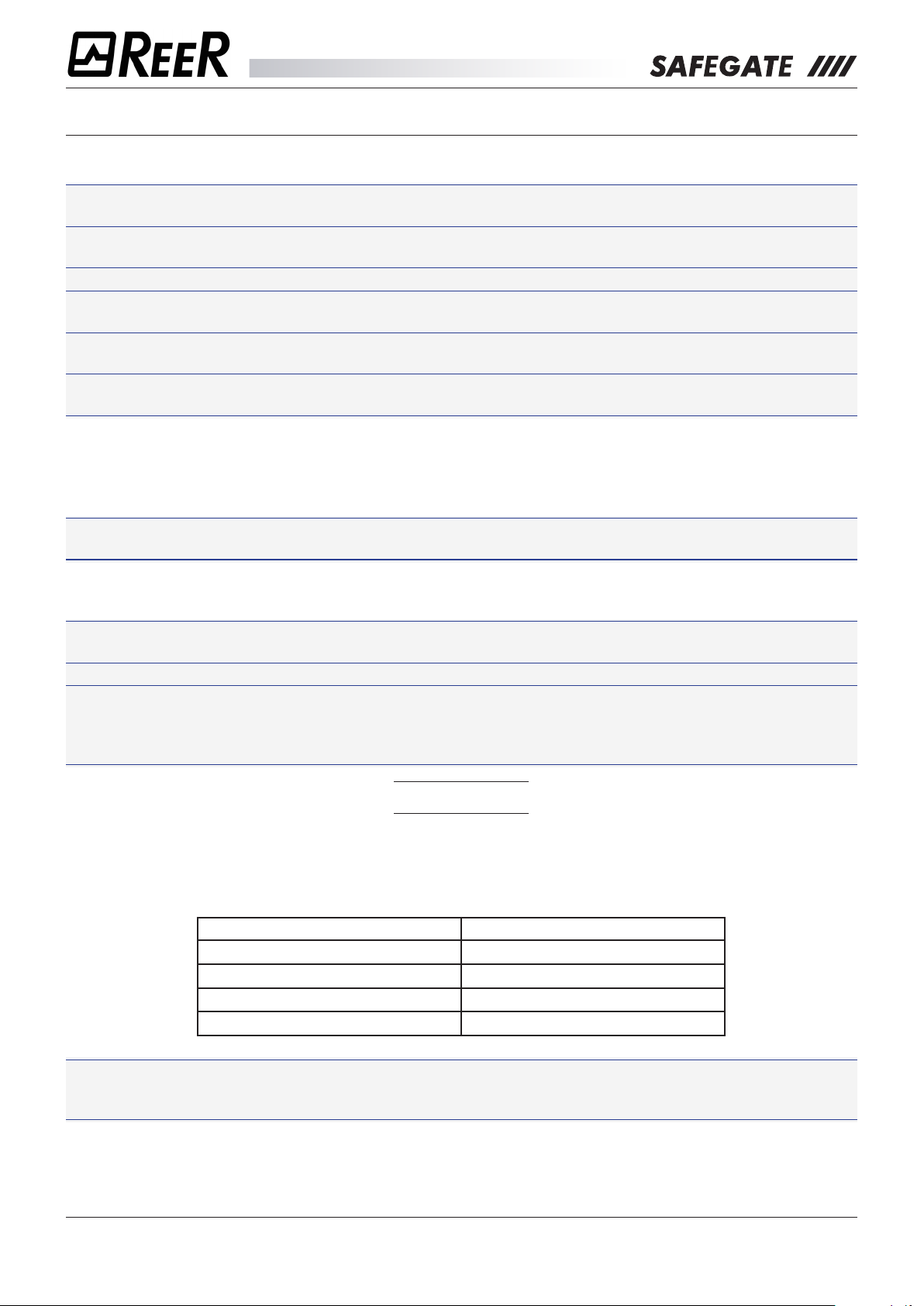
Before placing the safety device, it is important to consider the following general guidelines:
Verify that the temperature of the environment where the system is installed is compatible with the
temperature operating parameters indicated on the product label and in the technical data.
Avoid positioning the Emitter and Receiver near intense or ashing high-intensity light sources.
Specic environmental conditions may aect the level of detection of photoelectric devices.
In environments where fog, rain, smoke or dust may be present, it is advisable to use suitable Fc
correction factors at the maximum useful values of the working range to ensure the correct operation
of the equipment. In these cases:
Pu = Pm x Fc
where Pu and Pm are respectively the working range and maximum range in metres.
Recommended Fc factors are shown in the following table.
ENVIRONMENTAL CONDITION CORRECTION FACTOR Fc
Fog 0,25
Steam 0,50
Powders 0,50
Dense smoke 0,25
If the device is placed in environments subject to sudden temperature uctuations, it is imperative
to take the appropriate steps to avoid condensation on the lenses, which may impair the detection
capability.
8541150 - rev.1 - 10/07/2017
REER S.p.A. - 32 via Carcano - 10153 Torino Italia Internet: www.reer.it - e-mail: info@reer.it
8
Page 9
Safety
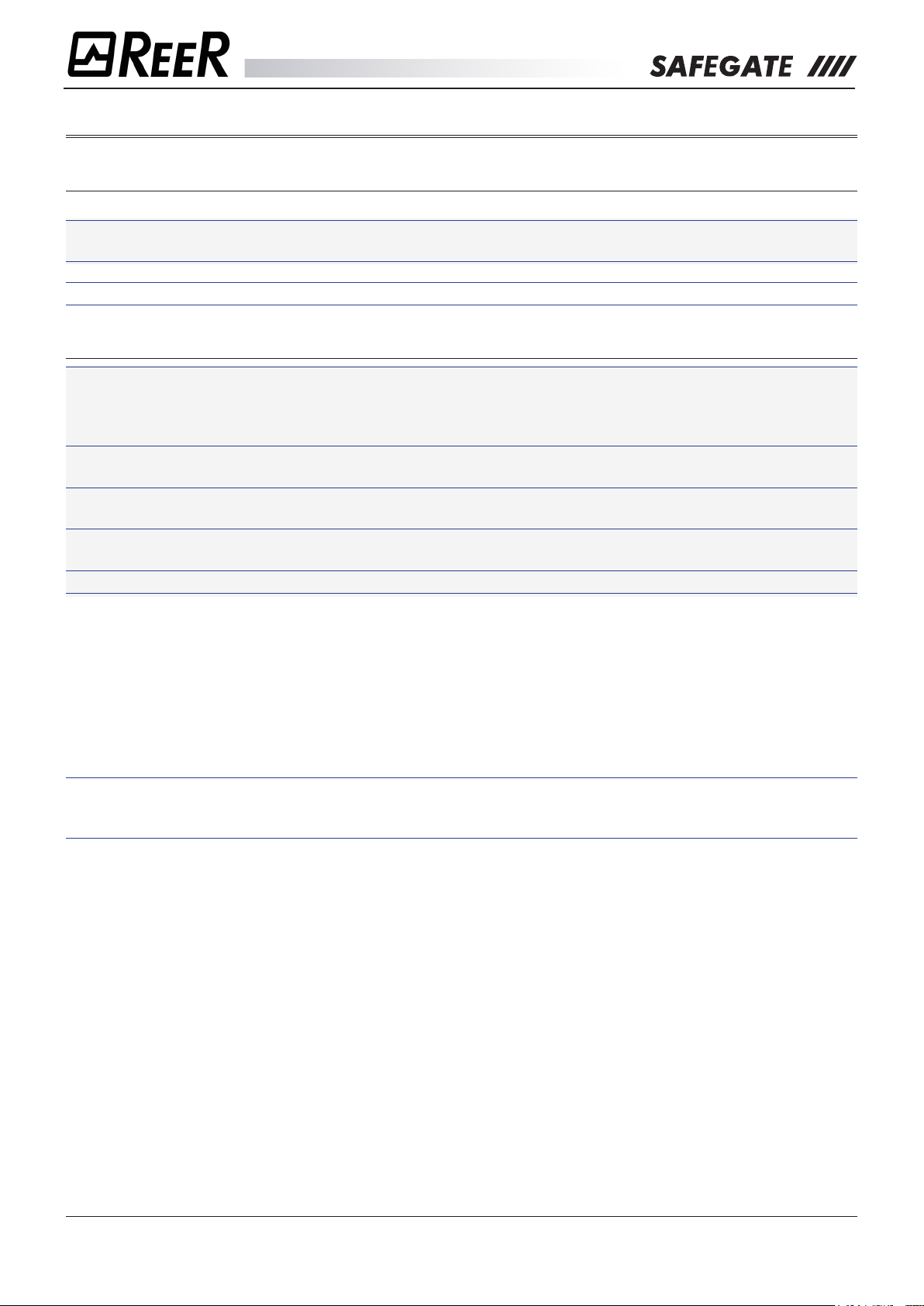
LIST OF APPLICABLE STANDARDS
SAFEGATE is manufactured in compliance with the following European Directives:
2006/42/EC “Machinery Directive”
2014/30/EU “Electromagnetic Compatibility Directive”
And it complies with the following Standards:
Safety level
Tipo 4
¾ EN 61496-1:2013
¾ EN 61496-2:2013
¾ IEC 61508-1:(ed.2)
SIL 3
¾ IEC 61508-2:(ed.2)
¾ IEC 61508-3:(ed.2)
¾ IEC 61508-4:(ed.2)
SILCL 3 ¾ IEC 62061:2005/A2:2015
PL e - Cat. 4 ¾ EN ISO 13849-1: 2015
8541150 - rev.1 - 10/07/2017
REER S.p.A. - 32 via Carcano - 10153 Torino Italia Internet: www.reer.it - e-mail: info@reer.it
9
Page 10

Safety
EC DECLARATION OF CONFORMITY
Dichiarazione CE di conformità
EC declaration of conformity
REER SpA
via Carcano 32
10153 – Torino
Italy
dichiara che le barriere fotoelettriche SAFEGATE sono Dispositivi Elettrosensibili di Sicurezza (ESPE) di :
Tipo 4 (secondo la Norma EN 61496-1:2013; EN 61496-2:2013)
SIL 3 (secondo la Norma EN 61508-1:2010; EN 61508-2:2010; EN 61508-3:2010; EN 61508-4:2010)
SILCL 3 (secondo la Norma EN 62061:2005/A2:2015)
Cat.4 - PL e (secondo la Norma EN ISO 13849-1:2015)
declares that the SAFEGATE photoelectric safety barr
Type 4 (according the Standard EN 61496-1:2013; EN 61496-2:2013)
SIL 3 (according the Standard EN 61508-1:2010; EN 61508-2:2010; EN 61508-3:2010; EN 61508-4:2010)
SILCL 3 (according the Standard EN 62061:2005/A2:2015)
Cat.4 - PL e (according the Standard EN ISO 13849-1:2015)
Electro-sensitive Protective Equipments (ESPE)
realizzati in conformità alle se
guenti Direttive Europee:
complying with the following European Directives:
2006/42/EC "Direttiva Macchine"
"Machine Directive"
2014/30/EU "Direttiva Compatibilità Elettromagnetica"
"Electromagnetic Compatibility Directive"
e alle seguenti Norme: /and to the following Standards:
EN 50178: 1997
EN 55022: 2006
EN 61000-6-2: 2005
e sono identiche all'esemplare esaminato ed approvato con esame di tipo CE da:
and are identical to the specimen examined and approved with a CE - type approval by:
TÜV SÜD Product Service GmbH – Zertifizierstelle – Ridlerstraße 65 – 80339 – München – Germany
N.B
. number: 0123 - Certificate No: Z10 17 05 24820 071
Carlo Pautasso Simone Scaravelli
Direttore Tecnico Amministratore Delegato
Technical Director Managing director
iers are :
Torino, 15/06/2017
8541150 - rev.1 - 10/07/2017
REER S.p.A. - 32 via Carcano - 10153 Torino Italia Internet: www.reer.it - e-mail: info@reer.it
10
Page 11
System architecture
SYSTEM ARCHITECTURE
SAFEGATE is supplied as a pair (Emitter/Receiver) and allows integration with external Muting sensors
that are directly connected to the connectors installed on the curtain.
¾ Each curtain can be congured as LX, L2, TX and T4 (see the dierent Muting types in the section
“MUTING FUNCTION”) through the wiring of the main connector. This conguration can be changed
at any time.
¾ SAFEGATE can be used with (pre-aligned and pre-congured) Muting arms, with M5 multibeam
photocells (available as accessories) or any other Muting sensor.
¾
S models integrate the functions of “START/RESTART INTERLOCK” and ”EDM” but do not allow the
Muting function.
¾
SM models allow the Muting function, but have no integrated signal lamp.
¾ Programmable
problems in complex application scenarios.
¾
SMO-SMPO models with Integrated signalling lamp allow the immediate viewing of the curtain status
even at a distance.
SMP-SMPO models allow an ideal use of further conguration options to solve potential
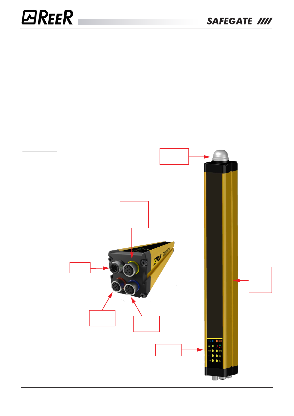
PLEASE NOTE
The sample gure represents the Receiver
of a SMPO model.
This model comes with integrated signal
lamp.
Additionally, the conguration connector
allows the USB connection to a PC with
the conguration software installed.
Main
connector
Integrated
Signalling
Lamp
Configuration
connector
and auxiliary
signal lamp
Seat for
anchorage
of any
Muting
arms
Sensor 3-4
Muting
connector
8541150 - rev.1 - 10/07/2017
REER S.p.A. - 32 via Carcano - 10153 Torino Italia Internet: www.reer.it - e-mail: info@reer.it
Sensor 1-2
Muting
connector
Signals
label
11
Page 12

System architecture
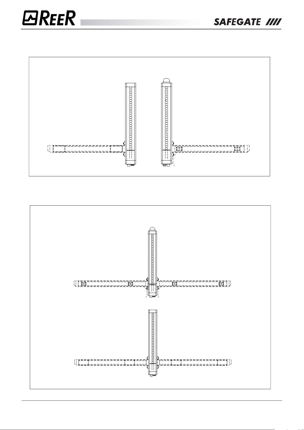
POSSIBLE CONFIGURATIONS (via optional accessories)
MAL2X - braccetti L a 2 raggi incrociati TX/RX
MAL2X - L-arms with 2 crossed TX/RX beams
MAL2XE
EMITTER
Optional
Accessorio
Accessory
opzionale
MAT2X - T-arms with 2 crossed TX/RX beams
MAT2X - braccetti T a 2 raggi incrociati TX/RX
MAT2XE SX
EMITTER
Optional
Accessorio
opzionale
Accessory
SAFEGATE - EMITTER
SAFEGATE - RECEIVER
SAFEGATE - EMITTER
MAT2XE DX
EMITTER
Optional
Accessorio
Accessory
opzionale
MAL2XR
RECEIVER
Optional
Accessorio
Accessory
opzionale
SAFEGATE - RECEIVER
MAT2XR SX
RECEIVER
Optional
Accessorio
opzionale
Accessory
MAT2XR DX
RECEIVER
Accessorio
Accessory
opzionale
8541150 - rev.1 - 10/07/2017
REER S.p.A. - 32 via Carcano - 10153 Torino Italia Internet: www.reer.it - e-mail: info@reer.it
Optional
12
Page 13
System architecture
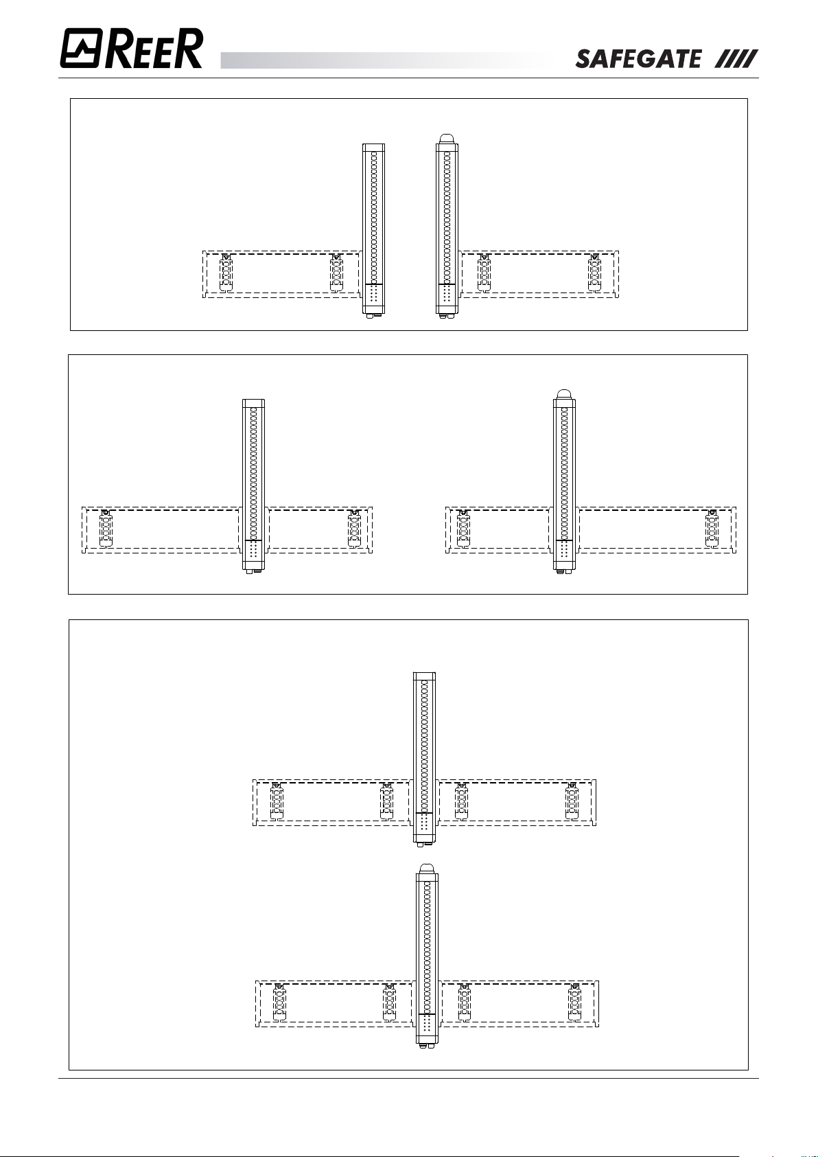
MAL2P TRX - L-arms with 2 parallel beams with reector
MAL2P TRX - braccetti L a 2 raggi paralleli con riflettore
MA2P SX 2R
REFLECTOR
Optional
Accessorio
Accessory
opzionale
MAT4P TRX - T arms with 4 parallel beams with reectors
MAT4P TRX - braccet. T a 4 raggi paralleli con riflettore
MA2P SX 2B
EMITTER / RECEIVER EMITTER / RECEIVER
Optional
Accessorio
Accessory
opzionale
SAFEGATE - EMITTER
SAFEGATE - RECEIVER
SAFEGATE - RECEIVER
MA2P DX 2B
EMITTER / RECEIVER
Optional
Accessorio
Accessory
opzionale
MA2P DX 2B
Optional
Accessorio
Accessory
opzionale
MA2P SX 2R
Optional
Accessorio
Accessory
opzionale
8541150 - rev.1 - 10/07/2017
REER S.p.A. - 32 via Carcano - 10153 Torino Italia Internet: www.reer.it - e-mail: info@reer.it
SAFEGATE - EMITTER
MA2P DX 2R
REFLECTORREFLECTOR
Optional
Accessorio
Accessory
opzionale
13
Page 14
System architecture
MZL2XP arms with 2 cross-linked/parallel adjustable M5 beams
MZL2XP - braccetti L a 2 raggi incrociati/paralleli regolabili M5
MZL2XPE MZL2XPR
EMITTER RECEIVER
Optional
Accessorio
Accessory
opzionale
MZT2X - T-arms with 2 adjustable M5 cross beams
MZT2X - braccetti T a 2 raggi incrociati regolabili M5
SAFEGATE - EMITTER
SAFEGATE - RECEIVER
Optional
Accessorio
Accessory
opzionale
MZT2XE SX
EMITTER RECEIVEREMITTER RECEIVER
Optional
Accessorio
Accessory
opzionale
SAFEGATE - EMITTER
MZT4P - T-arms with 4 adjustable M5 parallel beams
MZT4P - braccetti T a 4 raggi paralleli regolabili M5
MZT2XE DX
Optional
Accessorio
Accessory
opzionale
MZT4PE SX MZT4PE DX
EMITTER
Optional
Accessorio
Accessory
opzionale
SAFEGATE - EMITTER
MZT2XR SX
Optional
Accessorio
Accessory
opzionale
EMITTER
Optional
Accessorio
Accessory
opzionale
SAFEGATE - RECEIVER
MZT2XR DX
Optional
Accessorio
Accessory
opzionale
MZT4PR SX MZT4PR DX
RECEIVER
Optional
Accessorio
Accessory
opzionale
SAFEGATE - RECEIVER
8541150 - rev.1 - 10/07/2017
REER S.p.A. - 32 via Carcano - 10153 Torino Italia Internet: www.reer.it - e-mail: info@reer.it
RECEIVER
Optional
Accessorio
Accessory
opzionale
14
Page 15
The Muting function
THE MUTING FUNCTION
The Muting function is the temporary exclusion of the safety curtain, automatically and safely carried out
based on the machine cycle.
ÎÎ Carefully verify your risk analysis to make sure the Muting function is compatible with your
application and what additional measures should be taken.
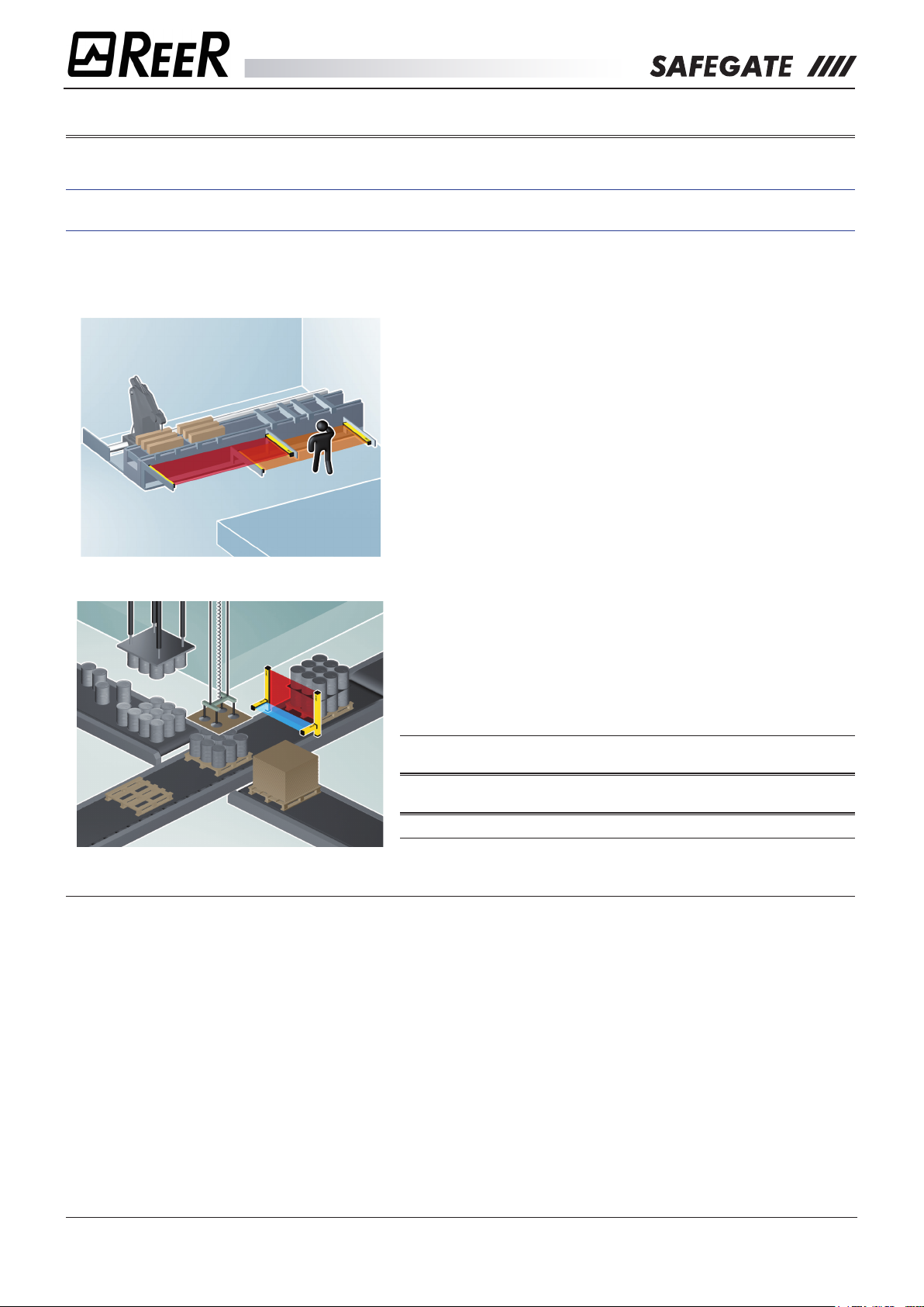
There are basically two types of applications:
1. Those allowing people to enter the dangerous area during the non-dangerous part of the machine
cycle.
Example:
Positioning or Removing the workpiece
Depending on the position of the tool, which is the hazardous
element, one of the two curtains (the one facing the tool
work area) is active while the other is in Muting condition
to allow the operator loading/unloading the workpiece. The
Muting condition of the two curtains will then be reversed
when the tool is to work on the opposite side of the machine.
2. Those who allow material transit and prevent access to the people.
Example: Pallet exit from the hazardous area
The safety curtain is equipped with Muting sensors able to
eectively discriminate between the person and the material
allowed to get through the controlled gate. The essential
requirements concerning the Muting function are described
in the following Standards:
ÎÎ IEC TS 62046 - “Application of protection devices for people
detection”.
ÎÎ EN 415-4 - “Safety on packaging machines – Palletizers and
Unpalletizers”.
ÎÎ IEC 61496-1 - “Electro-sensitive protective devices”.
General requirements:
¾ The Muting function is a temporary suspension of the safety function that needs to be activated and
deactivated automatically.
¾ The activation and subsequent deactivation of the Muting function must take place only through the use
of two or more wired and independent signals activated by a correct timing or spatial sequence. This
means that a stand-alone failure cannot activate the Muting function.
¾ It should not be possible to activate the Muting function when SAFEGATE has deactivated the safety
outputs.
¾ It should not be possible to start a Muting function by switching o and then restarting the device.
¾ Muting must be activated at an appropriate point of the machine cycle, i.e. only when there are no risks
for the operator.
¾ Muting sensors must be mechanically protected so that any impact does not modify their alignment.
8541150 - rev.1 - 10/07/2017
REER S.p.A. - 32 via Carcano - 10153 Torino Italia Internet: www.reer.it - e-mail: info@reer.it
15
Page 16
The Muting function
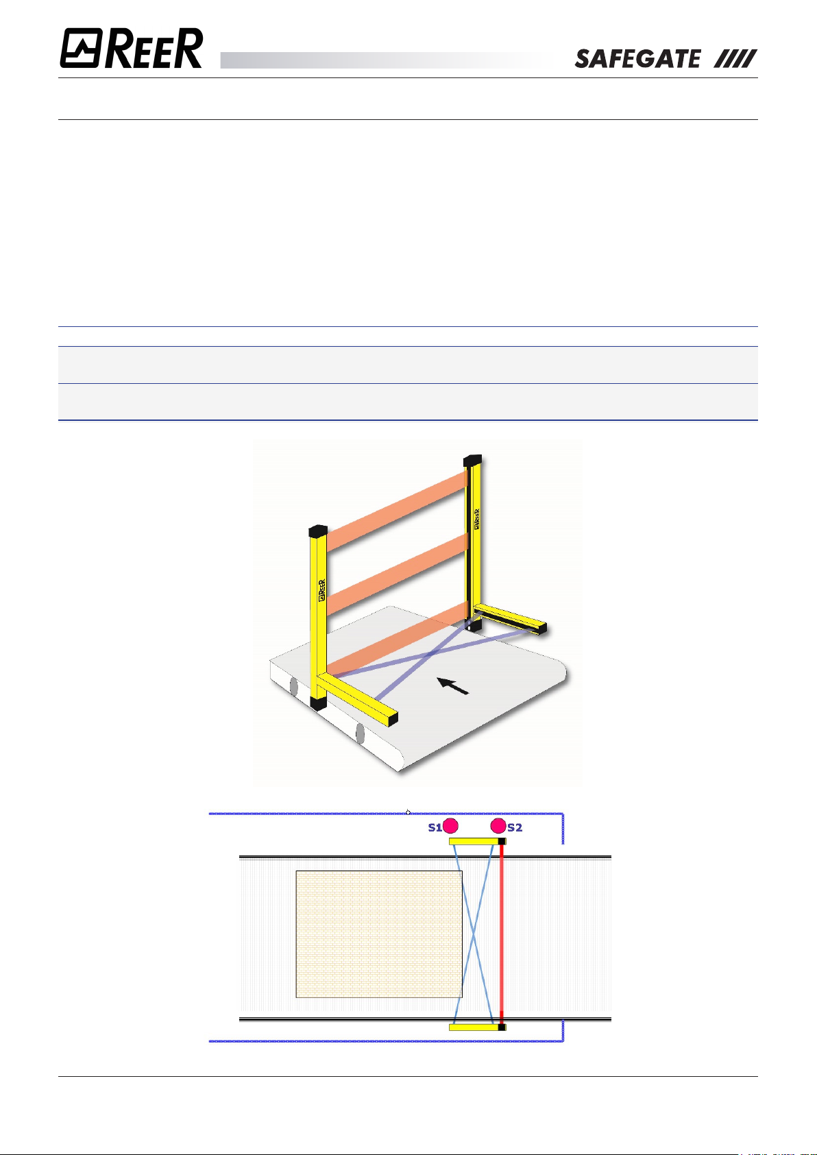
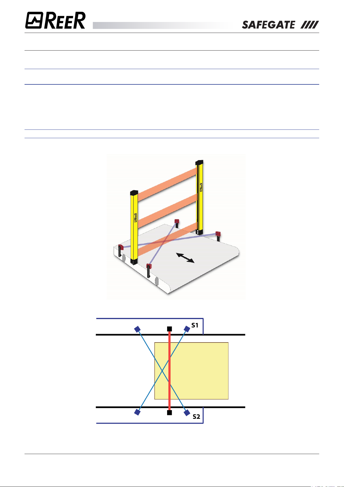
A) 2 INTEGRATED CROSS MUTING SENSORS, ONLY FOR PALLET OUTPUTS (LX)
In this way sensors 1 and 2 are on the same side as the vertical curtain and are placed in front of the
dangerous gate. This mode is unidirectional and is useful for protecting gates with pallet output.
The activation of the Muting function occurs after the simultaneous interruption (within 4 sec maximum) of
S1 and S2 sensors. As long as both sensors remain busy, the Muting function continues. When the rst of
the 2 sensors is released, the material will still have 4 seconds to leave the protected area limited by the
curtain. The Muting condition will be disabled as soon as the protected area is released.
At the end of 4 seconds, if the curtain is still busy, the OSSD outputs are disabled by interrupting the
operation of the machine. This allows selecting the maximum duration of the Muting condition (timeout) as
30 seconds or 9 hours.
ÎÎ Other timings are available with programmable programs.
Î For the safe operation of the LX conguration, it is absolutely essential that the horizontal Muting
sensor elements are located within the hazardous area.
Î The minimum distance between two consecutive pallets must be less than 10 cm or greater than
32cm.
8541150 - rev.1 - 10/07/2017
REER S.p.A. - 32 via Carcano - 10153 Torino Italia Internet: www.reer.it - e-mail: info@reer.it
16
Page 17
The Muting function
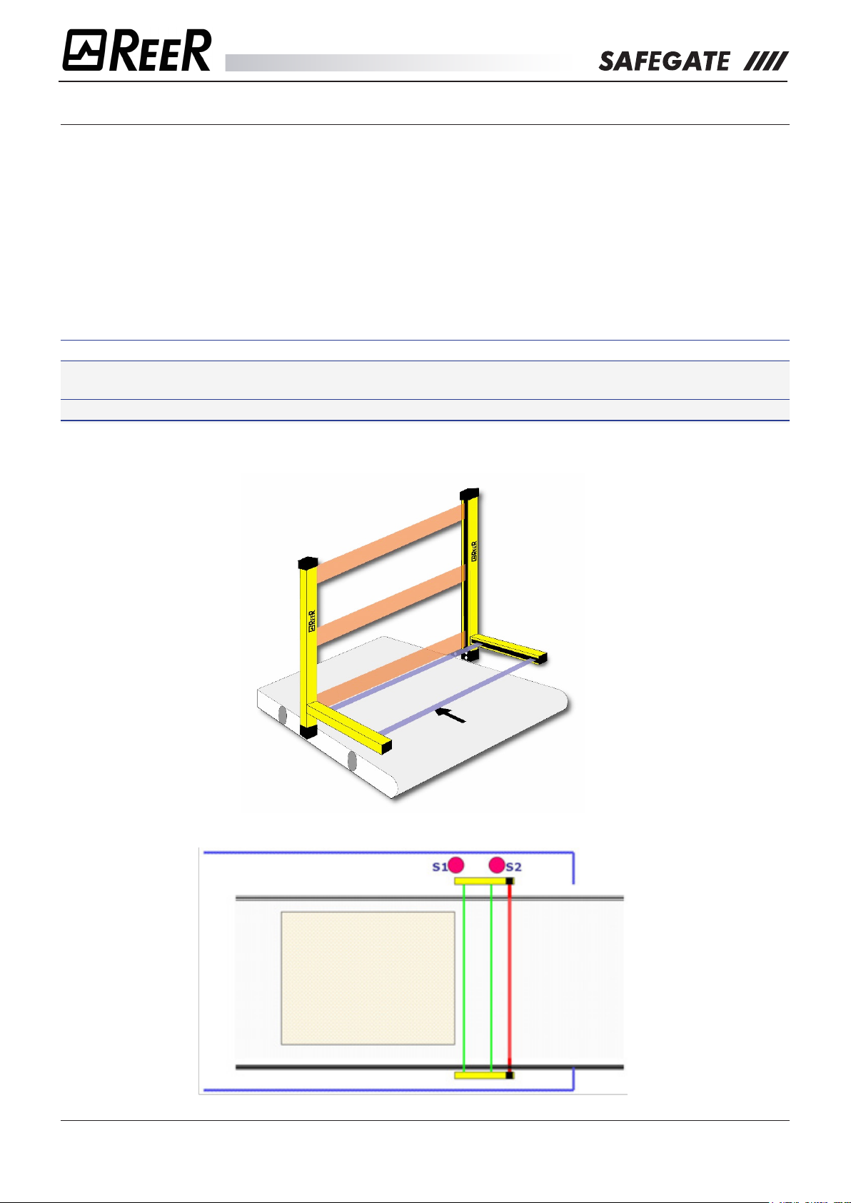
B) 2 INTEGRATED PARALLEL MUTING SENSORS, ONLY FOR PALLET OUTPUTS (L2)
In this way sensors 1 and 2 are on the same side as the vertical curtain and are placed in front of the
dangerous gate. This mode is unidirectional and is useful for protecting gates with pallet output.
The activation of the Muting function occurs after the simultaneous interruption (within max 4 sec) of
sensors S1 and S2. As long as both sensors remain busy, the Muting function continues. When the rst
of the 2 sensors is released, the material will still have 4 seconds to leave the protected area limited by
the curtain. The Muting condition will be disabled as soon as the protected area is released. At the end of
4 seconds, if the curtain is still busy, the OSSD outputs are disabled by interrupting the operation of the
machine.
This allows selecting the maximum duration of the Muting condition (timeout) as 30 seconds or 9 hours.
ÎÎ Other timings are available with programmable programs.
Î For the safe operation of the L2 conguration, it is imperative that horizontal Muting sensors are
located within the hazardous area.
Î The minimum distance between two consecutive pallets must be greater than 40 cm.
8541150 - rev.1 - 10/07/2017
REER S.p.A. - 32 via Carcano - 10153 Torino Italia Internet: www.reer.it - e-mail: info@reer.it
17
Page 18
The Muting function
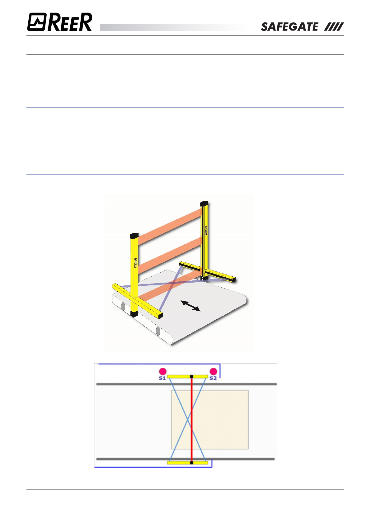
C) 2 INTEGRATED CROSS MUTING SENSORS, FOR BI-DIRECTIONAL GATES (TX)
In this way, the two Muting sensors are each rst on a dierent side of the vertical curtain.
This mode is unidirectional and is useful for protecting gates with pallet output.
ÎÎ The crossing point of the two Muting sensors must be placed inside the hazardous area to avoid
undesirable and dangerous activations of the Muting function.
The activation of the Muting function occurs after the simultaneous interruption (within max 4 sec) of
sensors S1 and S2. As long as both sensors remain busy, the Muting function continues. By releasing the
rst of the two sensors, the Muting function is disabled.
This mode also allows selecting the maximum duration of the Muting condition (timeout) as 30 seconds or
9 hours.
ÎÎ Other timings are available with programmable programs.
8541150 - rev.1 - 10/07/2017
REER S.p.A. - 32 via Carcano - 10153 Torino Italia Internet: www.reer.it - e-mail: info@reer.it
18
Page 19
The Muting function
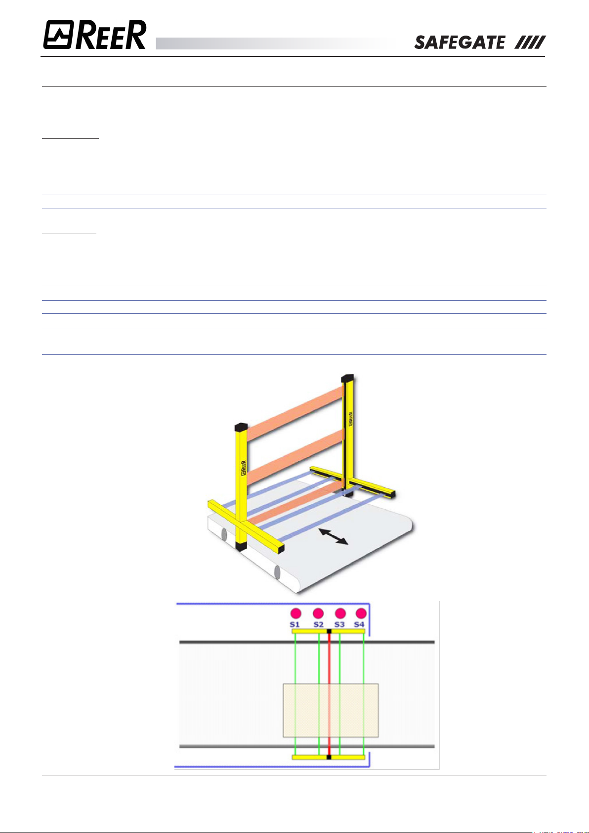
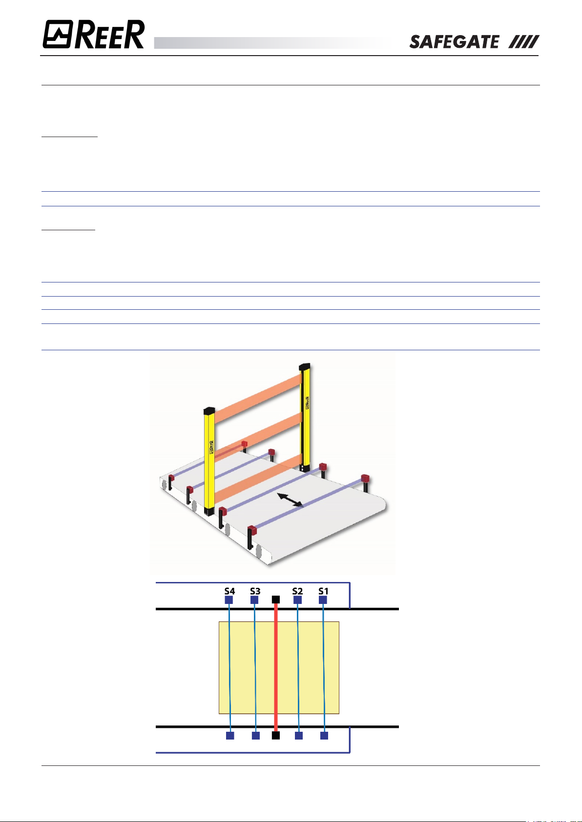
D) 4 INTEGRATED PARALLEL MUTING SENSORS, FOR BI-DIRECTIONAL GATES (T4)
This mode is bidirectional and is useful for protecting gates with pallet output.
Using this mode, two dierent modes of operation are outlined:
Concurrent
The activation of the Muting function occurs after the sensors S1 and S2 are interrupted (within max 4sec)
(or S4 and S3 with material moving in the opposite direction).
The Muting state ends after the release of the gate, and of the S3 sensor (or S2 with material moving in
the opposite direction).
ÎÎ For the T4 models (concurrent operation), there are two available timeouts: 1) 30 sec; 2) 9 hours.
Sequential
The activation of the Muting function occurs after the sequential interruption of sensors S1 and S2 (or S4
and S3 with material moving in the opposite direction) without time limitations.
The Muting state ends after the release of the gate, and of the S3 sensor (or S2 with material moving in
the opposite direction).
ÎÎ For the T4 models (sequential operation), there are two available timeouts: 1) 30 sec; 2) innite.
ÎÎ Other timings are available with programmable programs.
ÎÎ In both modes of operation, the minimum pallet length must be 70 cm (to ensure simultaneous
occupancy of all four sensors).
8541150 - rev.1 - 10/07/2017
REER S.p.A. - 32 via Carcano - 10153 Torino Italia Internet: www.reer.it - e-mail: info@reer.it
19
Page 20
The Muting function
E) 2 EXTERNAL CROSS INTEGRATED MUTING SENSORS, FOR BI-DIRECTIONAL GATES (TX).
This mode is bidirectional and is useful for protecting gates with pallet output.
ÎÎ The crossing point of the two Muting sensors must be placed inside the hazardous area to avoid
undesirable and dangerous activations of the Muting function.
The activation of the Muting function occurs after the simultaneous interruption (within max 4 sec) of
sensors S1 and S2. As long as both sensors remain busy, the Muting function continues. When the rst
of the two sensors is released, the Muting function is disabled. In this mode of operation the maximum
duration of the Muting condition (timeout) can be selected in 30 seconds or 9 hours.
ÎÎ Other timings are available with programmable programs.
8541150 - rev.1 - 10/07/2017
REER S.p.A. - 32 via Carcano - 10153 Torino Italia Internet: www.reer.it - e-mail: info@reer.it
20
Page 21
The Muting function
F) 4 EXTERNAL PARALLEL MUTING SENSORS, FOR BI-DIRECTIONAL GATES (T4).
This mode is bidirectional and is useful for protecting gates with pallet output.
Using this mode, two dierent modes of operation are outlined:
Concurrent
The activation of the Muting function occurs after the sensors S1 and S2 are interrupted (within max 4
sec) (or S4 and S3 with material moving in the opposite direction).
The Muting state ends after the release of the gate, and of the S3 sensor (or S2 with material moving in
the opposite direction).
ÎÎ For the T4 models (concurrent operation), there are two available timeouts: 1) 30 sec; 2) 9 hours.
Sequential
The activation of the Muting function occurs after the sequential interruption of sensors S1 and S2 (or S4
and S3 with material moving in the opposite direction).
The Muting state ends after the release of the gate, and of the S3 sensor (or S2 with material moving in
the opposite direction).
ÎÎ For the T4 models (sequential operation), there are two available timeouts: 1) 30 sec; 2) innite.
ÎÎ Other timings are available with programmable programs.
ÎÎ In both modes of operation, the minimum pallet length must be 70 cm (to ensure simultaneous
occupancy of all four sensors).
8541150 - rev.1 - 10/07/2017
REER S.p.A. - 32 via Carcano - 10153 Torino Italia Internet: www.reer.it - e-mail: info@reer.it
21
Page 22
The Muting function
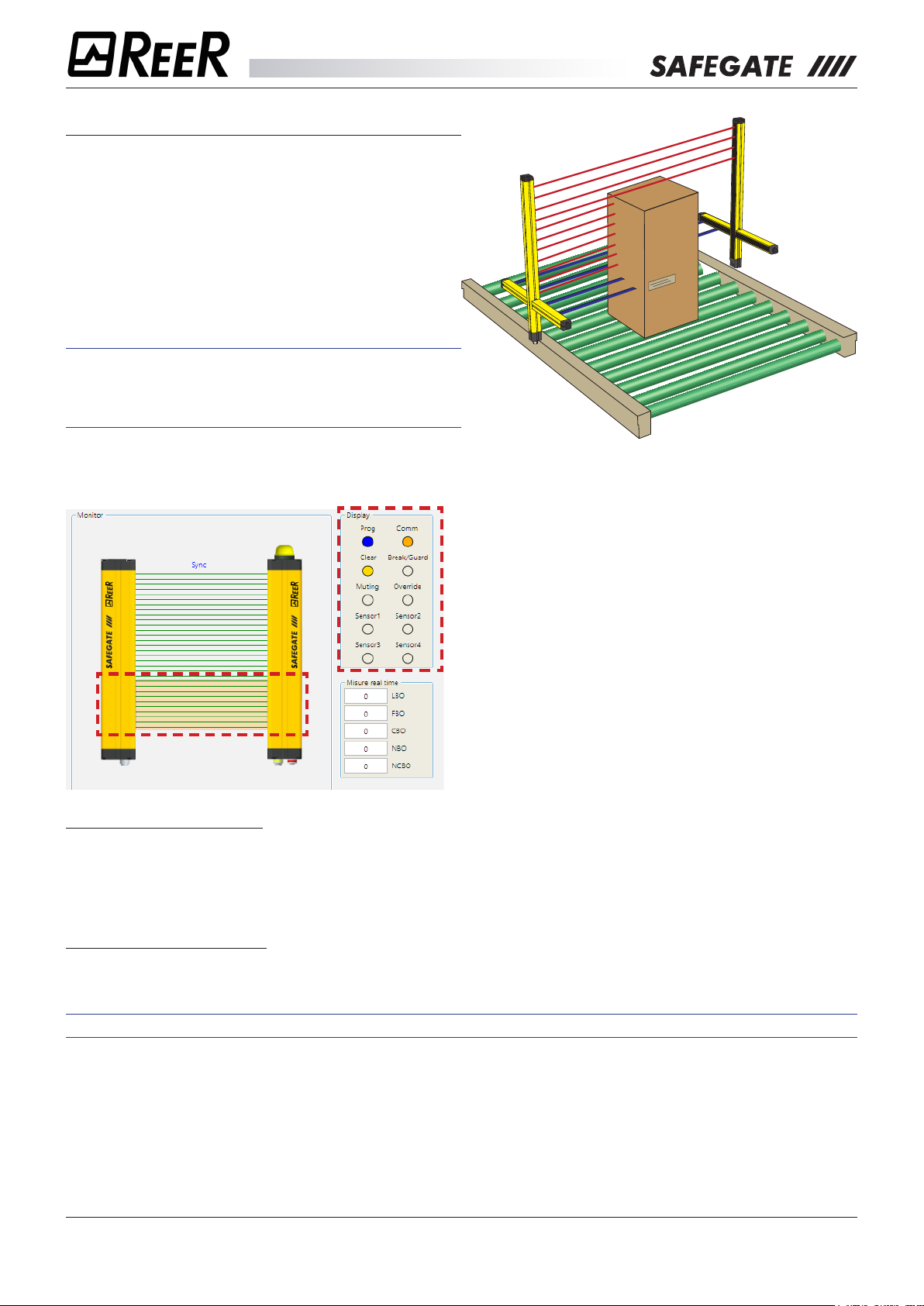
PARTIAL MUTING
The Partial Muting feature allows you to limit the
Muting function to a number of well-dened beams.
By this function, you can enable the Muting function
only for those beams that will be interrupted by the
passage of the material (e.g. lower pallets at the end
of the product cycle). The remaining beams, however,
can be kept active to protect the dangerous gate.
ÎÎ This function is only available on SMP/SMPO
models and must be managed through the
Safegate Congurator software (select “Partial
Muting Enabling”).
The software should then select the number of beams aected by Partial Muting, taking into account that
the rst Partial Muting beam always starts from the bottom (connectors side).
For this operation, it may be useful to verify the
Monitor software function (free beams are indicated
by dierent colouring than the busy ones) and the
various numerical information on the side (LBO,
FBO, etc.).
Only one value can be entered when programming
the number of beams aected by this function.
There are two types of partial Muting and, for both,
the “Partial Muting” input pin (pin 6 of M12 12-pin
connector on the receiver) must be used.
Partial Muting with Enable
With this option, the Partial Muting function is normally deactivated. To activate this function, the input
signal (pin 6 of the receiver) must switch from LO to HI (rising edge) before starting the Muting cycle.
Partial Muting with Disable
With this option the Partial Muting function is normally active. To activate this function, the input signal (pin
6 of the receiver) must switch from LO to HI (rising edge) before starting the Muting cycle.
ÎÎ Refer to the “OPERATING MODES” section to correctly set this function.
8541150 - rev.1 - 10/07/2017
REER S.p.A. - 32 via Carcano - 10153 Torino Italia Internet: www.reer.it - e-mail: info@reer.it
22
Page 23

The Muting function
MUTING OVERRIDE
The OVERRIDE function becomes necessary when, after incorrect Muting activation sequences, the
machine stops leaving the material in the dangerous gate.
In this situation, the OSSD outputs are inactive because the curtain and/or at least one Muting sensor are
busy. In this condition, the OVERRIDE request LED ashes.
Î This operation activates the OSSD outputs to remove the material obstructing the gate.
Î During the entire phase in which the OVERRIDE function is active, the Override/Muting lamp ashes.
You should periodically verify the eciency of this lamp (during Muting or Override phases).
Î The Pulse Override command automatically activates the curtain outputs until both the curtain and
the Muting sensors are again free of obstacles. During this period the curtain is not able to protect
access to the dangerous gate. It is therefore necessary that all operations be conducted under close
supervision of experienced personnel.
The user will use the type of Override previously congured:
1. Override with spring return key
2. Override with pushbutton
Override with spring return key
Activation of this function must be done by bringing both receiver pins 9 and 10 to + 24VDC (within a 400
ms time window), for example by using a 2-way key switch with spring return.
Override has a maximum duration of 15 minutes; it can end due to two dierent causes.
1. When the selector is released or the 15 minutes expire, the override ends, bringing the outputs to
OFF, turning o the lamp, and returning the display to normal. However, it is still possible to start a
new override, releasing the selector and reactivating it.
2. At the release of the curtain and sensors (clear gate) the override ends and the GUARD condition is
reactivated (the curtain is working properly) without additional commands.
Override with pushbutton
The activation of this function must occur inverting (within a time window of 400 ms) the condition of pins
9 and 10 of the receiver through the use of a 2-way switch.
When override is active the condition of pins 9 and 10 is no longer veried.
MAXIMUM OVERRIDE TIME (MODELS WITH HARDWARE CONFIGURATION)
The override has a maximum duration of 15 minutes (repeatable).
The function can only restart if the button is pushed again (complying with the following conditions):
1. Maximum OVERRIDE time (after n consecutive requests) = 60 min
2. Maximum number of consecutive OVERRIDE requests = 30.
MAXIMUM OVERRIDE TIME (MODELS WITH SOFTWARE CONFIGURATION)
The function can only restart if the button is pushed again (complying with the following conditions):
1. Maximum OVERRIDE time (after n consecutive requests) = 4 x timeout override
2. Maximum number of consecutive OVERRIDE requests = 30.
At the release of the curtain and sensors (clear gate) the override ends and the GUARD condition is
reactivated (the curtain is working properly) without additional commands.
The timer (point 1) and the counter (point 2) are reset if one of the following conditions occurs:
¾ A proper sequence of Muting.
¾ A system reset (turning it o and on).
8541150 - rev.1 - 10/07/2017
REER S.p.A. - 32 via Carcano - 10153 Torino Italia Internet: www.reer.it - e-mail: info@reer.it
23
Page 24
Mechanical installation
INSTALLATION
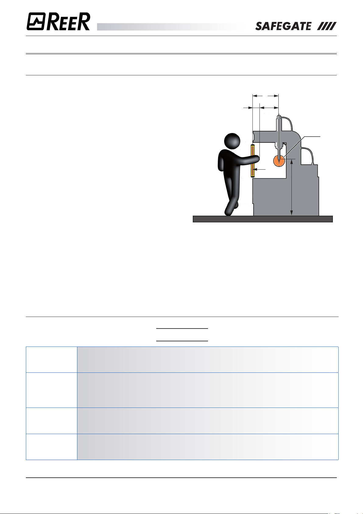
CALCULATION OF THE SAFETY DISTANCE
The eectiveness of the protection heavily depends
on the correct positioning of the curtain according
to the danger. The curtain must be positioned at a
distance greater than or equal to the minimum safety
distance S so that reaching the dangerous point can
only be achieved after the dangerous operation of the
machine has stopped.
The positioning shall be such that:
• Reaching the dangerous point is avoided without
crossing the area controlled by the curtain.
• No person is allowed in the dangerous area
without this being detected. For this case,
additional safety devices (e.g. horizontal light
curtains) may be required.
S
C KxT
1
2
a
The ISO 13855 standard provides the elements for
3
calculating the safety distance.
1. Dangerous point
If the machine under consideration is subject to a type
C specic standard, reference should be made to this
rule.
2. Protected plane
3. Reference plane
a. Height of dangerous point
S. Safety distance
If the S distance calculated appears to be excessive,
it is necessary:
• to reduce the total time the machine is o
• to improve the resolution of the curtain.
GENERAL FORMULA FOR CALCULATING THE SAFETY DISTANCE
S = K x T + C
S
K
minimum safety distance between the protection and the dangerous point, expressed in mm.
advance speed of the body or parts of the body, expressed in mm per second.
K values can be:
K = 2000 mm per second for safety distances up to 500 mm
K = 1600 mm per second for safety distances over 500 mm
Total machine stopping time including:
T
C
8541150 - rev.1 - 10/07/2017
REER S.p.A. - 32 via Carcano - 10153 Torino Italia Internet: www.reer.it - e-mail: info@reer.it
T1 response time of the protection device in seconds
T2 machine reaction time to stop the hazardous operation, in seconds.
additional distance expressed in mm.
24
Page 25
Mechanical installation
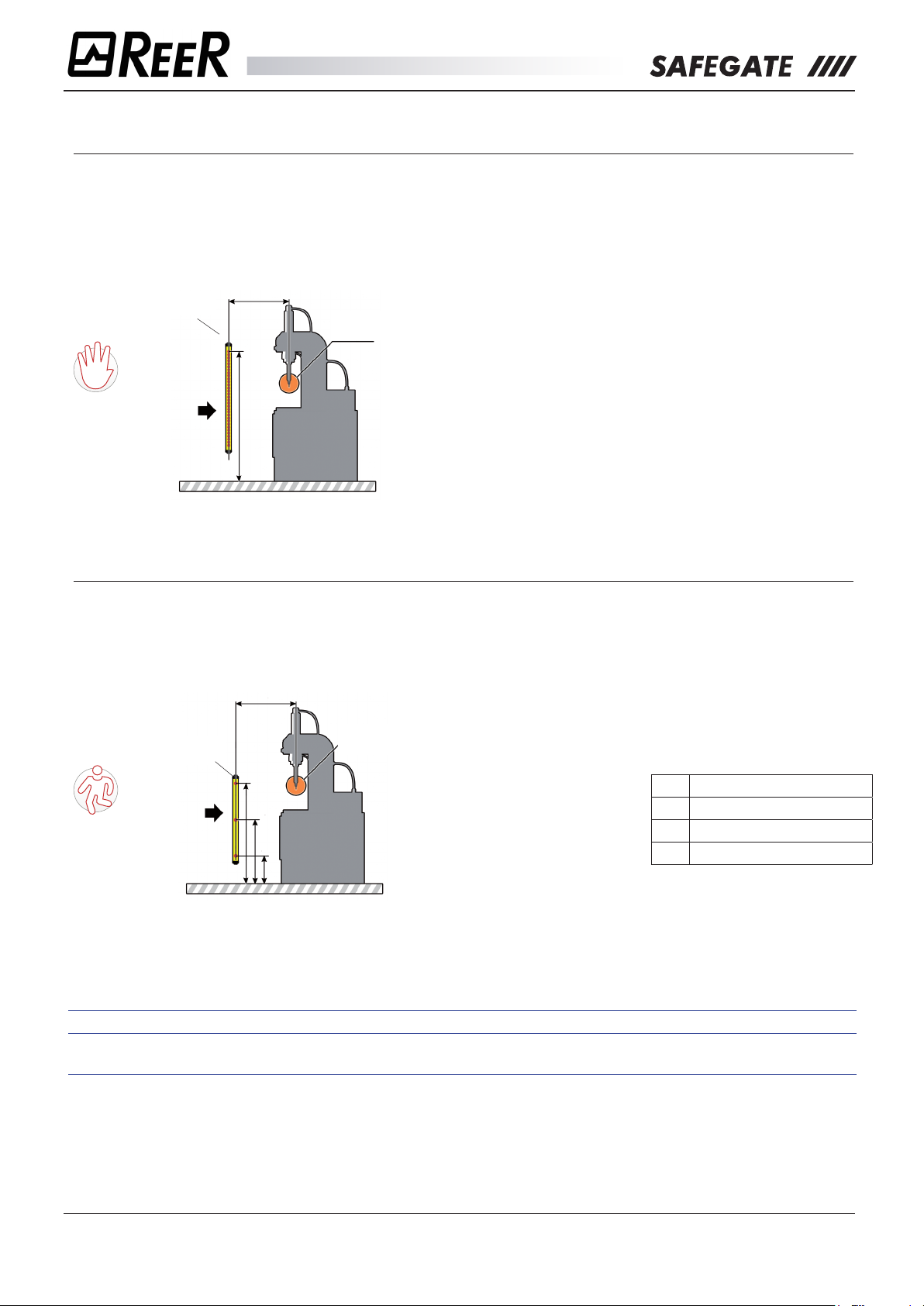
MODELS WITH RESOLUTION 30 mm – 40 mm
Curtains with resolution
for arms detection.
Curtain resolution (d) 30 - 40 mm
S
Protected
plane
H
MODELS WITH 2/3/4 beams
Body detection curtains.
Curtain with 2/3/4 beams
Dangerous
point
Calculating the minimum
safety distance (S)
Refer to the general formula
for the safety distance
calculation.
S = K x T + C
S = 2000xT + 8x(d-14)
If the formula provides as a
result: S>500 it’s possible to
use
K=1600
S = 1600xT + 8x(d-14)
(with C = 8x(d-14))
• The S distance must
not be less than
100mm
• If the resulting
distance S is greater
than 500 mm, you
can recalculate the
distance using K =
1600.
• In this case the
distance must still not
be less than 500 mm.
S
Recommended height
according to the number
of beams
N° Recommended height
2 400 - 900 mm
3 300 - 700 - 1100 mm
4 300 - 600 - 900 - 1200 mm
Protected
plane
H≥1100
H≥700
H≤300
Dangerous
point
Refer to the general formula
for the safety distance
calculation.
S = K x T + C
S = 1600xT + 850
ÎÎ The S distance must not be less than 100 mm
ÎÎ If the resulting distance S is greater than 500 mm, it is possible to recalculate the distance using
K = 1600 but in this case the distance must still not be less than 500 mm
8541150 - rev.1 - 10/07/2017
REER S.p.A. - 32 via Carcano - 10153 Torino Italia Internet: www.reer.it - e-mail: info@reer.it
25
Page 26
Mechanical installation
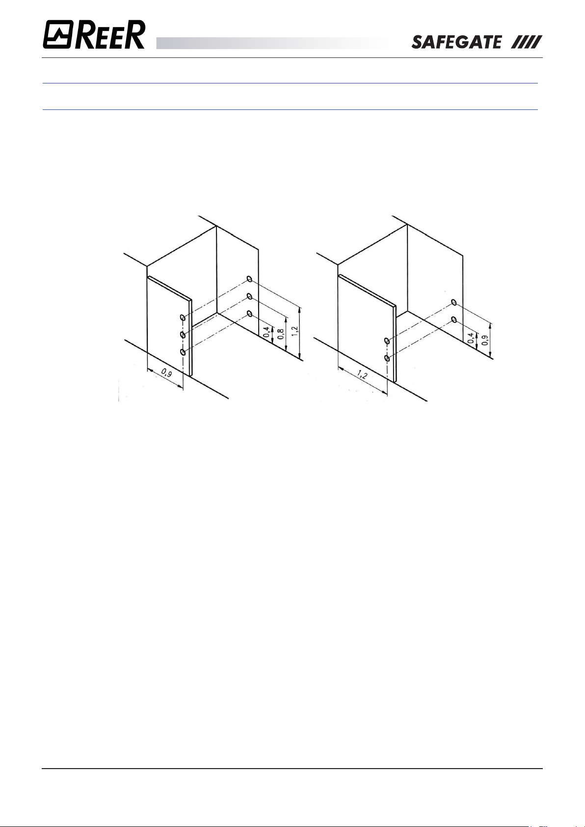
ÎÎ For applications on packaging machines (palletizers and unpalletizers), follow the instructions in
European standard EN 415-4, which are repeated here.
From low level (oor)
Device with 3 beams at least
Dimensions in m
Above the conveyor (rollers)
Device with 2 beams at least
8541150 - rev.1 - 10/07/2017
REER S.p.A. - 32 via Carcano - 10153 Torino Italia Internet: www.reer.it - e-mail: info@reer.it
26
Page 27
Mechanical installation
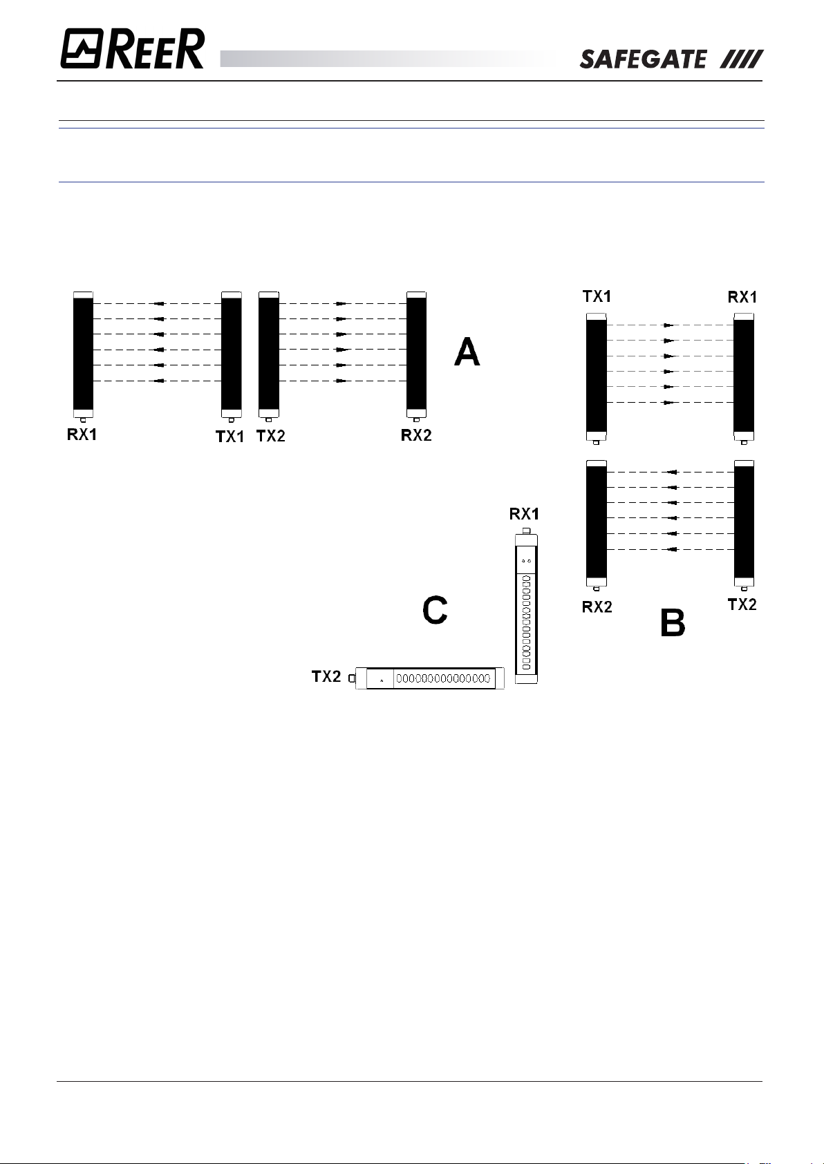
MULTIPLE SYSTEMS
ÎÎ When using multiple SAFEGATE systems, it is necessary to avoid them interfering optically with one
another: position the elements so that the beam emitted by the system Emitter is received only by
the respective Receiver.
The following gure shows some examples of correct positioning between the two photoelectric systems.
An incorrect positioning may cause interference, leading to an abnormal operation.
Systems side by side: A
Adjacent positioning of the two projectors
Overlapping systems: B
“L” combination: C
Cross-positioning between
projectors and receivers
8541150 - rev.1 - 10/07/2017
REER S.p.A. - 32 via Carcano - 10153 Torino Italia Internet: www.reer.it - e-mail: info@reer.it
27
Page 28

Mechanical installation
USE OF DEFLECTING MIRRORS
For the protection or control of multiple accessed areas, one or more deecting mirrors can be used in
addition to the Emitter and the Receiver.
The deecting mirrors allow in fact returning the optical beams generated by the Emitter on
multiple sides.
If you want to deect by 90° the beams emitted by the Emitter, the perpendicular to the surface of the
mirror should make a 45° angle with the direction of the beams.
The following gure shows an application in which two deecting mirrors are used to make a “U” protection.
Dangerous zone
S
S
When making use of deecting mirrors consider the following rules:
¾ Position the mirrors so that the minimum safety distance S is kept on each of the sides to access the
hazardous area.
¾ The working distance (range) is the sum of the lengths of all sides accessing the guarded area.
(Please note that the maximum working range between Emitter and Receiver is reduced by 15% for
each mirror used).
¾ When installing, pay particular attention to not to twist along the longitudinal axis of the mirror.
¾ Verify, by positioning near and on the Receiver axis, that in the rst mirror you see the whole shape of
the Emitter.
¾ It is recommended that you use no more than three deecting mirrors.
S
8541150 - rev.1 - 10/07/2017
REER S.p.A. - 32 via Carcano - 10153 Torino Italia Internet: www.reer.it - e-mail: info@reer.it
28
Page 29

DISTANCE FROM REFLECTING SURFACES
Î The presence of reective surfaces located near the light curtain
can cause spurious reections preventing the detection. Referring to the
S
A
following Figure object A is not detected due to the plane S reecting the
beam and thus closing the optical path between the Emitter and Receiver.
It is therefore necessary to keep a minimum distance d between any
reecting surfaces and the protected area. For calculating the minimum
distance d, it is recommended to use the values set for Type 4 devices
according to IEC/EN 61496-2.
The following gure shows the above-mentioned values of the distance d
based on the distance between the Emitter and the Receiver.
Mechanical installation
DISTANCE (mm)
RANGE (m)
ÎÎ Once the system is installed, verify any reective surfaces which may intercept the beams, rst
in the centre and then near the Emitter and Receiver. During this procedure, the red LED on the
Receiver must never go o.
8541150 - rev.1 - 10/07/2017
REER S.p.A. - 32 via Carcano - 10153 Torino Italia Internet: www.reer.it - e-mail: info@reer.it
29
Page 30

Mechanical installation
MECHANICAL ASSEMBLY AND OPTICAL ALIGNMENT
Î The following operations must only be carried out by qualied personnel, otherwise you may lose
the machine safety function.
¾ The Emitter and the Receiver must be mounted one in front of the other at a distance equal to or less
than that indicated in the technical data; Using the supplied inserts and brackets, position the Emitter
and the Receiver so that they are aligned and parallel to each other and with the connectors facing the
same side.
¾ The perfect alignment between Emitter and Receiver is essential for the smooth operation of the curtain;
this operation is facilitated by observing the Emitter and Receiver signalling LEDs.
¾ Make electrical connections according to the directions of the dedicated chapter.
ÎÎ Pay particular attention to the SAFEGATE model you are connecting.
Connections may vary depending on the model.
¾ Place the optical axis of the rst and last beams of the Emitter on the same axis as that of the
corresponding beams on the Receiver.
¾ Move the Emitter to nd the area within which the green LED on the Receiver stays on, then place the
rst transmitter beam (the one near the signal LED) at the centre of this area.
¾ Using this beam as a pivot, with small lateral displacements of the opposite end, move to the free
guarded area condition, which in this situation will be indicated by turning on the green LED on the
Receiver.
¾ Firmly tighten the Emitter and the Receiver.
ÎÎ If the Emitter and the Receiver are mounted in areas subject to strong vibrations, in order not to
compromise the operation of the circuits, it is necessary to use anti-vibration dampers.
8541150 - rev.1 - 10/07/2017
REER S.p.A. - 32 via Carcano - 10153 Torino Italia Internet: www.reer.it - e-mail: info@reer.it
30
Page 31

Electrical connections/Operating modes
Modelli SM, SMO, SMP, SMPO
(3) 0VDC
CONNESSIONI EMETTITORE
SM - SMO MODELS ELECTRICAL CONNECTIONS
Before proceeding to the electrical connections make sure that the available power supply voltage is in
accordance with the data specied in the technical data.
The Emitter and the Receiver must be powered with a voltage of 24Vdc ± 20%.
The external power supply must comply with EN 60204-1.
In order to ensure the declared Environmental Protection Degree (IP65-IP67), it is mandatory to
protect the unused connectors with the provided protection caps.
PRECAUTIONS
• Make the connection to earth before making any other connections.
• Connect Safegate before energizing.
• The ground connection (0VDC) must be common to all system components.
WARNINGS ON CONNECTION CABLES
• Conductor Size: 0,25÷2,5 mm2.
• It is recommended to keep SAFEGATE’s power supply separate from that of other electrical power equipment
(electric motors, inverters, frequency changers) or other sources of disturbance.
• For cables more than 20 m long, cables with a section of at least 0.5 mm
length over 50 m).
2
must be used (AWG16), (1 mm2 with a
EMITTER CONNECTIONS
0VDC (3)
(1) 24VDC
(4) 0VDC
(1) 24VDC
(5) PE
(4) RANGE1
(2) SYNC
(“Table 1”, page 32)
(“Table 2”, page 32)
(2) SYNC
(1) 24VDC
PE
(3) 0VDC
(“Table 3”, page 32)
8541150 - rev.1 - 10/07/2017
REER S.p.A. - 32 via Carcano - 10153 Torino Italia Internet: www.reer.it - e-mail: info@reer.it
(5) PE
(4) 0VDC
(“Table 4”, page 32)
31
Page 32

Electrical connections/Operating modes
Table 1
RANGE/TEST SELECTION MALE CONNECTOR - M12 - 5-PIN
PIN COLOUR SIGNAL IN/OUT DESCRIPTION ELECTRICAL LEVEL
1 Brown 24VDC - Power supply 24 VDC Positive
2 White RANGE0 Input Range selection (see table “RANGE AND TEST SELECTION”)
3 Blue 0VDC - Power supply 0VDC Negative
4 Black RANGE1 Input Range selection (see table “RANGE AND TEST SELECTION”)
5 Grey PE - Earth connection -
Table 2
RANGE AND TEST SELECTION - M12 - 5-PIN
PIN 2 PIN 4 FUNCTION
24VDC 0VDC LOW range
0VDC 24VDC HIGH range
(For range values, refer to the Technical Features table)
0VDC 0VDC Curtain under TEST (Refer to paragraph “TEST FUNCTION”)
24VDC 24VDC - Condition not allowed
Table 3
FEMALE CONNECTOR POWER SUPPLY SENSORS MUTING 1 - 2 - M12 - 5-PIN
PIN COLOUR SIGNAL IN/OUT DESCRIPTION ELECTRICAL LEVEL
1 Brown 24VDC - Sensor Power Supply 24VDC Positivoe
2 White SYNC Output Synchronization with M5 arms LL0->0Vdc; LL1->24Vdc
3 Blue 0VDC - Sensor Power Supply 0VDC Negative
4 Black 0VDC - Sensor Power Supply 0VDC Negative
5 Grey PE - EARTH CONNECTION -
Table 4
FEMALE CONNECTOR POWER SUPPLY SENSORS MUTING 3 - 4 - M12 - 5-PIN
PIN COLOUR SIGNAL IN/OUT DESCRIPTION ELECTRICAL LEVEL
1 Brown 24VDC - Sensor Power Supply 24VDC Positivoe
2 White SYNC Output Synchronization with M5 arms LL0->0Vdc; LL1->24Vdc
3 Blue 0VDC - Sensor Power Supply 0VDC Negative
4 Black 0VDC - Sensor Power Supply 0VDC Negative
5 Grey PE - EARTH CONNECTION -
8541150 - rev.1 - 10/07/2017
REER S.p.A. - 32 via Carcano - 10153 Torino Italia Internet: www.reer.it - e-mail: info@reer.it
32
Page 33

Electrical connections/Operating modes
Modelli SM, SMO
(4) SENSOR3
(3) 0VDC
RECEIVER CONNECTIONS
0VDC (2)
OSSD1 (3)
OSSD2 (4)
PE (5)
SEL_B (11)
(“Table 5”, page 33)
(1) 24VDC
(3) 0VDC
(“Table 8”, page 34)
(2) SENSOR4
(5) PE
(10) OVER1_RESTART
(1) 24VDC
(9) OVERRIDE2
(8) EDM
(7) MUTING_ENABLE
(12) STATUS
(6) SEL_A
(2) N.C.
MUT_LAMP (1)
(5) N.C.
N.C. (4)
(“Table 6”, page 34)
(2) SENSOR2
(3) 0VDC
(1) 24VDC
(5) PE
(4) SENSOR1
(“Table 7”, page 34)
Table 5
MAIN MALE CONNECTOR - M12 - 12 PIN
PIN COLOUR SIGNAL IN/OUT DESCRIPTION ELECTRICAL LEVEL
1 Brown 24VDC - POWER SUPPLY 24 VDC -
2 Blue 0VDC - POWER SUPPLY 0VDC -
3 White OSSD1 Output STATIC SAFETY OUTPUTS PNP active high
4 Green OSSD2 Output
5 Pink PE - EARTH CONNECTION -
6 Yellow SEL_A Input MUTING CONFIGURATION
7 Black MUT_ENABLE Input
8 Grey EDM Input FEEDBACK K1/K2
9 Red OVERRIDE2 Input OVERRIDE REQUEST
10 Violet
11 Grey/ Pink SEL_B Input MUTING CONFIGURATION
12 Red/Blue STATUS Output SYSTEM STATUS PNP active high
EXTERNAL MUTING
ENABLE
OVERRIDE1
Input
RESTART RESTART INTERLOCK
OVERRIDE REQUEST
Refer to “SELECTION OF OPERATING
MODES”, page 35
Safegate considers the muting cycle correct if it
detects a “MUTING ENABLE” signal rising edge
before the use of the sensors
External contactors feedback ”EDM”, page 36
Refer to the section “OVERRIDE”, page 37
Refer to the section “OVERRIDE”, page 37
Refer to the table “RESTART (MANUAL
OPERATION)”, page 38
Refer to the section “SELECTION OF
OPERATING MODES”, page 35
8541150 - rev.1 - 10/07/2017
REER S.p.A. - 32 via Carcano - 10153 Torino Italia Internet: www.reer.it - e-mail: info@reer.it
33
Page 34

Electrical connections/Operating modes
Table 6
MUTING LAMP FEMALE CONNECTOR, CURTAIN PROGRAMMING
PIN COLOUR SIGNAL IN/OUT DESCRIPTION ELECTRICAL LEVEL
1 Brown MUT_LAMP Output Muting Lamp activation command Active Muting 24VDC
2 White n.c. - - 3 Blue 0VDC - Muting Lamp 0VDC 0VDC
4 Black n.c. - 5 Grey n.c. - - -
Table 7
FEMALE CONNECTOR POWER SUPPLY SENSORS MUTING 1 - 2 - M12 - 5-PIN
PIN COLOUR SIGNAL IN/OUT DESCRIPTION ELECTRICAL LEVEL
1 Brown 24VDC - Sensor Power Supply 24VDC Positive
2 White SENSOR2 Input SENSOR 2 Status
3 Blue 0VDC - Sensor Power Supply 0VDC Negative
4 Black SENSOR1 Input SENSOR 1 Status
5 Grey PE - EARTH CONNECTION -
< 5VDC : CLEAR SENSOR
11÷30 VDC : ACTUATED SENSOR
< 5VDC : CLEAR SENSOR
11÷30 VDC : ACTUATED SENSOR
Table 8
FEMALE CONNECTOR POWER SUPPLY/SENSORS MUTING 3 - 4 - M12 - 5-PIN
PIN COLOUR SIGNAL IN/OUT DESCRIPTION ELECTRICAL LEVEL
1 Brown 24VDC - Sensor Power Supply 24VDC Positive
2 White SENSOR4 Input SENSOR 4 Status
3 Blue 0VDC - Sensor Power Supply 0VDC Negative
4 Black SENSOR3 Input SENSOR 3 Status
5 Grey PE - EARTH CONNECTION -
< 5VDC : CLEAR SENSOR
11÷30 VDC : ACTUATED SENSOR
< 5VDC : CLEAR SENSOR
11÷30 VDC : ACTUATED SENSOR
Î Using LX or TX conguration with 2 sensors: SENSOR1 wiring is mandatory, while the position of the
second muting sensor is the operator’s choice between SENSOR2 and SENSOR3.
TEST FUNCTION
By means of the test function, which simulates occupation of the protected area, it possible to verify the
operation of the entire system by means of an external supervisor (e.g. PLC, control module, etc.). The
SAFEGATE barrier system features an automatic self-diagnosis function that enables it to detect response
time malfunctions (this time is declared for each model).
This safety system is permanently active and does not require any interventions from the outside.
The TEST function is available should the user wish to check equipment connected downstream of the
barrier (without physically entering the protected area). By means of this function the OSSDs can be
switched from ON to OFF as long as the function remains active.
Î The minimum duration of the TEST function must be 40 msec.
8541150 - rev.1 - 10/07/2017
REER S.p.A. - 32 via Carcano - 10153 Torino Italia Internet: www.reer.it - e-mail: info@reer.it
34
Page 35

Electrical connections/Operating modes
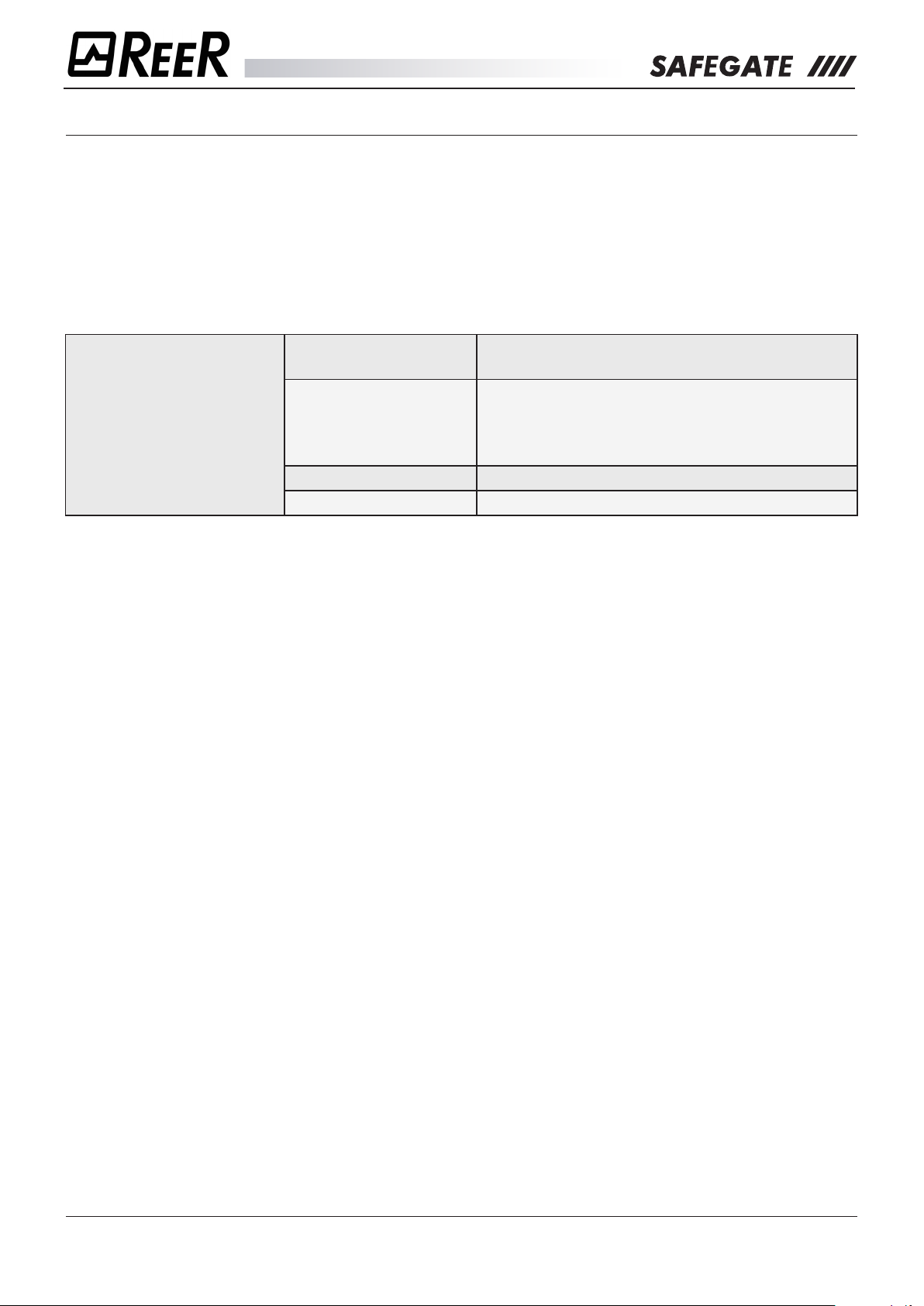
SELECTION OF OPERATING MODES
The inputs available to the SAFEGATE receiver (main male connector - M12 - 12pin) allow the conguration
of the various operating modes.
It is therefore necessary, when switching on, to properly connect the SAFEGATE receiver inputs for proper
operation, as shown below.
The following tables allow the user to congure the type of Muting to be adopted in terms of: MUTING
MODE, TIMEOUT MUTING, OVERRIDE TYPOLOGY.
SEL_A (pin 6) SEL_B (pin 11) MODALITÀ MUTING MUTING TIMEOUT
24VDC (1) OSSD1 (3) 4 SENSORS, SEQUENTIAL 30 s
24VDC (1) OSSD2 (4) 4 SENSORS, SEQUENTIAL ∞
OSSD2 (4) OSSD1 (3) 2 SENSORS, “TX” MODE 30 s
OSSD1 (3) OSSD2 (4) 2 SENSORS, “TX” MODE 9 hours
OSSD1 (3) 24VDC (1) 2 SENSORS, “L” MODE 30 s
OSSD2 (4) 24VDC (1) 2 SENSORS, “L” MODE 9 hours
MANUAL MODE
OSSD2 (4) OSSD2 (4) 4 SENSORS CONCURRENT 30 s
OSSD1 (3) OSSD1 (3) 4 SENSORS CONCURRENT 9 hours
n.c. / 0VDC n.c. / 0VDC Conguration error
n.c. / 0VDC n.c. / 0VDC SPM/SPMO models: programming needed
SEL_A (pin 6) SEL_B (pin 11) MODALITÀ MUTING MUTING TIMEOUT
24VDC (1) 24VDC (1) 4 SENSORS, SEQUENTIAL 30 s
STATUS (12) STATUS (12) 4 SENSORS, SEQUENTIAL ∞
24VDC (1) STATUS (12) 2 SENSORS, “TX” MODE 30 s
STATUS (12) 24VDC (1) 2 SENSORS, “TX” MODE 9 ore
STATUS (12) OSSD1 (3) 2 SENSORS, “L” MODE 30 s
OSSD1 (3) STATUS (12) 2 SENSORS, “L” MODE 9 ore
STATUS (12) OSSD2 (4) 4 SENSORS CONCURRENT 30 s
AUTOMATIC MODE
OSSD2 (4) STATUS (12) 4 SENSORS CONCURRENT 9 ore
n.c. / 0VDC n.c. / 0VDC Conguration error
n.c. / 0VDC n.c. / 0VDC SPM/SPMO models: programming needed
Î To program SMP / SMPO models it is mandatory that pin 6 and 11 of the 12 pin connector on the
receiver detect 0VDC (or open circuit).
8541150 - rev.1 - 10/07/2017
REER S.p.A. - 32 via Carcano - 10153 Torino Italia Internet: www.reer.it - e-mail: info@reer.it
35
Page 36

Electrical connections/Operating modes
Hardware configuration
EDM (8)
OSSD2 (12)
SAFEGATE
RECEIVER
EDM enabled
EDM (8)
OSSD2 (12)
SAFEGATE
RECEIVER
EDM disabled
+24VDC
FBK K1 FBK K2
EDM
The EDM function (external K1 / K2 control) can be enabled / disabled via hardware:
EDM ACTIVATED
SAFEGATE awaits a signal with inverse logic to the condition of the external contactors:
¾ OSSD1 / OSSD ON: External contacts K1/K2 closed: EDM = OPEN CIRCUIT
¾ OSSD1 / OSSD OFF: External contacts K1/K2 open: EDM = CLOSED CIRCUIT
Connect the pin 8 of the 12 poles connector to the Receiver as shown above.
Î The time allowed to elapse from the activation of the OSSD outputs and the opening of the FBK
contacts must be t <500ms.
8541150 - rev.1 - 10/07/2017
REER S.p.A. - 32 via Carcano - 10153 Torino Italia Internet: www.reer.it - e-mail: info@reer.it
36
Page 37

Electrical connections/Operating modes
OVERRIDE
SAFEGATE allows you to congure two dierent types of override; (See paragraph “MUTING OVERRIDE”,
page 23 for the description of the following function).
OVERRIDE1 (pin 10) OVERRIDE2 (pin 9) SELEZIONE
0 0 Override with spring return key
0 1 Override with button
1 0 Wrong conguration
1 1
OVERRIDE WITH KEY WITH SPRING RETURN KEY
The function starts with the simultaneous activation of the two OVERRIDE inputs according to the following
table:
OVERRIDE1 (pin 10) OVERRIDE2 (Pin 9)
0 0
1 1
Both signals are active at 24VDC and the function only starts if they are activated at the same time (within
a maximum delay of 400 ms) and the key is kept active for at least 400 ms.
OVERRIDE WITH PUSHBUTTON
The function starts with the simultaneous activation of the two OVERRIDE inputs according to the following
table:
OVERRIDE1 (pin 10) OVERRIDE2 (Pin 9)
0 1
1 0
The function starts only if the signals are activated at the same time (within a maximum delay of 400 ms)
and the button is held pressed for at least 400 ms.
8541150 - rev.1 - 10/07/2017
REER S.p.A. - 32 via Carcano - 10153 Torino Italia Internet: www.reer.it - e-mail: info@reer.it
37
Page 38

Electrical connections/Operating modes
SAFEGATE
RECEIVER
AUTOMATIC
SAFEGATE
RECEIVER
MANUAL
OVERRIDE1
RESTART (10)
24Vdc
RESTART
SAFEGATE
RECEIVER
MANUAL
24Vdc
RESTART (MANUAL OPERATION)
Pin 10 has RESTART function. As a result of occupation of the protected area, outputs will be deactivated
(Manual mode - start/restart interlock enabled). To reactivate them you will need to repeat the sequence:
¾ “0Vdc” → “24Vdc” → “0Vdc”.
¾ The high level (24Vdc) must be between 100 ms and 5 s.
OVERRIDE1
RESTART (10)
RESTART
Use in manual mode (start/restart interlock enabled) is mandatory in case the safety device
controls a gate to protect a dangerous area and a person, once crossed the gate, can stay
in the hazardous area without being detected (use as a ‘trip device’ according to IEC 61496).
The Restart command must be located outside the hazardous area, at a point where the
hazardous area and the entire working area concerned are clearly visible.
It must not be possible to reach the command from inside the hazardous area.
AUTOMATIC OPERATION
Thanks to the connection of the pin 10 on the main receiver connector, the operator can choose to enable
the AUTOMATIC operation.
In Automatic operating mode, the OSSD1 and OSSD2 safety outputs follow the status of the light curtain:
¾ with guarded area free, the outputs are ON.
¾ with guarded area occupied, they are OFF.
OVERRIDE1
RESTART (10)
If the SAFEGATE light curtain is used in AUTOMATIC mode, it will not be equipped with
a start/restart interlock circuit. In most applications, this safety function is mandatory.
Carefully evaluate the risks analysis of your own application.
8541150 - rev.1 - 10/07/2017
REER S.p.A. - 32 via Carcano - 10153 Torino Italia Internet: www.reer.it - e-mail: info@reer.it
N.C.
38
Page 39

Electrical connections/Operating modes
SAFEGATE
RECEIVER
MUT_ENABLE
SAFEGATE
RECEIVER
EXT_MUTING
ENABLE SIGNAL
MUT_ENABLE
MUTING ENABLE
SAFEGATE can be congured in such a way that the muting cycle only starts after a signal of valid
MUTING ENABLE.
Pin 7 (MUTING_ENABLE) and 12 (STATUS) must be connected at power up as indicated:
disabled
MUTING
ENABLE (7)
STATUS (12)
Disabled
Enabled
The Muting cycle is activated without considering the MUTING ENABLE signal
The Muting cycle is activated only with the correct transition of the MUTING
ENABLE signal (see gure below) and closes with the release of the last sensor.
Muting Enable active: correct Muting sequence
enabled
MUTING
ENABLE (7)
STATUS (12)
OPERATION
8541150 - rev.1 - 10/07/2017
REER S.p.A. - 32 via Carcano - 10153 Torino Italia Internet: www.reer.it - e-mail: info@reer.it
39
Page 40

Electrical connections/Operating modes
1 - WIRING CONFIGURATION
APPENDIX A: SM - SMO MODELS WIRING SAMPLES
GENERAL (MANUAL MODE)
OPERATION WIRING
RETURN KEY
RESTART
PULSE
OVERRIDE
RESTART
SPRING
OVERRIDE
24Vdc
24Vdc
GND
24Vdc
GND
OR
24Vdc
24Vdc
GND
24Vdc
GND
+24Vdc
GND
SAFEGATE
RECEIVER
24VDC (1), Brown
GND (2), Blue
OVERRIDE1_RST, (10)
Violet
OVERRIDE2 (9), Red
OVERRIDE1_RST (10)
Violet
OVERRIDE2 (9)
Red
EDM
NO
EDM
ENABLE
ON
ENABLE
OFF
24Vdc
K1
OSSD2 (4), Green
EXT_ENABLE INPUT
STATUS (12), Red/Blue
K2
}
}
*
}
* (See diagram 3, 4)
8541150 - rev.1 - 10/07/2017
REER S.p.A. - 32 via Carcano - 10153 Torino Italia Internet: www.reer.it - e-mail: info@reer.it
STATUS (12)
EDM (8), Grey
OSSD1 (3)
MUT_ENABLE (7)
Black
SEL_A (6)
Yellow
SEL_B (11)
Pink/Grey
Blue/Red
White
OSSD2 (4)
Green
PE (5)
Pink
*
}
*
PE
40
Page 41

Electrical connections/Operating modes
2 - WIRING CONFIGURATION
GENERAL (AUTOMATIC MODE)
OPERATION WIRING
24Vdc
PULSE
OVERRIDE
SPRING
RETURN KEY
OVERRIDE
GND
24Vdc
GND
OR
24Vdc
GND
24Vdc
GND
+24Vdc
GND
SAFEGATE
RECEIVER
24VDC (1), Brown
GND (2), Blue
OVERRIDE1_RST, (10)
Violet
OVERRIDE2 (9), Red
OVERRIDE1_RST (10)
Violet
OVERRIDE2 (9)
Red
EDM
NO
EDM
ENABLE
ON
ENABLE
OFF
24Vdc
K1
OSSD2 (4), Green
EXT_ENABLE INPUT
STATUS (12), Red/Blue
K2
}
}
*
}
* (See diagram 3, 4)
8541150 - rev.1 - 10/07/2017
REER S.p.A. - 32 via Carcano - 10153 Torino Italia Internet: www.reer.it - e-mail: info@reer.it
STATUS (12)
EDM (8), Grey
OSSD1 (3)
MUT_ENABLE (7)
Black
SEL_A (6)
Yellow
SEL_B (11)
Pink/Grey
Blue/Red
White
OSSD2 (4)
Green
PE (5)
Pink
*
}
*
PE
41
Page 42

Electrical connections/Operating modes
3 - WIRING CONFIGURATION - MANUAL
MUTING MODES OF OPERATION
+24Vdc
GND
SAFEGATE
RECEIVER
24VDC (1), Brown
GND (2), Blue
MUTING OPERATION
4 SENSORS, SEQUENTIAL, TIMEOUT 30s 24VDC (1) OSSD1 (3)
(Brown) (White)
4 SENSORS, SEQUENTIAL, TIMEOUT ∞ 24VDC (1) OSSD2 (4)
(Brown) (Green)
2 SENSORS, “TX” MODE, TIMEOUT 30 s OSSD2 (4) OSSD1 (3)
(Green) (White)
2 SENSORS, “TX” MODE, TIMEOUT 9 hours OSSD1 (3) OSSD2 (4)
(White) (Green)
2 SENSORS, “L” MODE, TIMEOUT 30 s OSSD1 (3) 24VDC (1)
(White) (Brown)
2 SENSORS, “L” MODE, TIMEOUT 9 hours OSSD2 (4) 24VDC (1)
(Green) (Brown)
SEL_A (6), Yellow
SEL_B (11), Pink/Grey
4 SENSORS CONCURRENT, TIMEOUT 30 s OSSD2 (4) OSSD2 (4)
(Green) (Green)
4 SENSORS CONCURRENT, TIMEOUT 9 hours OSSD1 (3) OSSD1 (3)
(White) (White)
8541150 - rev.1 - 10/07/2017
REER S.p.A. - 32 via Carcano - 10153 Torino Italia Internet: www.reer.it - e-mail: info@reer.it
PE (5), Pink
PE
42
Page 43

Electrical connections/Operating modes
4 - WIRING CONFIGURATION - AUTOMATIC
MUTING MODES OF OPERATION
+24Vdc
MUTING OPERATION
SAFEGATE
RECEIVER
24VDC (1), Brown
GND (2), Blue
GND
SEL_A (6), Yellow
SEL_B (11), Pink/Grey
4 SENSORS, SEQUENTIAL, TIMEOUT 30s 24VDC (1) 24VDC (1)
(Brown) (Brown)
4 SENSORS, SEQUENTIAL, TIMEOUT ∞ STATUS (12) STATUS (12)
(Blue/Red) (Blue/Red)
2 SENSORS, “TX” MODE, TIMEOUT 30 s 24VDC (1) STATUS (12)
(Brown) (Blue/Red)
2 SENSORS, “TX” MODE, TIMEOUT 9 hours STATUS (12) 24VDC (1)
(Blue/Red) (Brown)
2 SENSORS, “L” MODE, TIMEOUT 30 s STATUS (12) OSSD1 (3)
(Blue/Red) (White)
2 SENSORS, “L” MODE, TIMEOUT 9 hours OSSD1 (3) STATUS (12)
(White) (Blue/Red)
4 SENSORS CONCURRENT, TIMEOUT 30 s STATUS (12) OSSD2 (4)
(Blue/Red) (Green)
4 SENSORS CONCURRENT, TIMEOUT 9 hours OSSD2 (4) STATUS (12)
(Green) (Blue/Red)
8541150 - rev.1 - 10/07/2017
REER S.p.A. - 32 via Carcano - 10153 Torino Italia Internet: www.reer.it - e-mail: info@reer.it
PE (5), Pink
PE
43
Page 44

Electrical connections/Operating modes
Modelli SM, SMO, SMP, SMPO
(3) 0VDC
RANGE0 (2)
CONNESSIONI EMETTITORE
SMP - SMPO MODELS ELECTRICAL CONNECTIONS
Before proceeding to the electrical connections make sure that the available power supply voltage is in
accordance with the data specied in the technical data.
The Emitter and the Receiver must be powered with a voltage of 24Vdc ± 20%.
The external power supply must comply with EN 60204-1.
In order to ensure the declared Environmental Protection Degree (IP65-IP67), it is mandatory to
protect the unused connectors with the provided protection caps.
PRECAUTIONS
• Make the connection to earth before making any other connections.
• Connect Safegate before energizing.
• The ground connection (0VDC) must be common to all system components.
WARNINGS ON CONNECTION CABLES
• Conductor Size: 0,25÷2,5 mm2.
• It is recommended to keep SAFEGATE’s power supply separate from that of other electrical power equipment
(electric motors, inverters, frequency changers) or other sources of disturbance.
• For cables more than 20 m long, cables with a section of at least 0.5 mm
length over 50 m).
2
must be used (AWG16), (1 mm2 with a
EMITTER CONNECTIONS
0VDC (3)
(1) 24VDC
(4) 0VDC
(1) 24VDC
(5) PE
(4) RANGE1
(2) SYNC
PE
(“Table 1”, page 45)
(“Table 2”, page 45)
(2) SYNC
(1) 24VDC
(5) PE
(3) 0VDC
(“Table 3”, page 45)
8541150 - rev.1 - 10/07/2017
REER S.p.A. - 32 via Carcano - 10153 Torino Italia Internet: www.reer.it - e-mail: info@reer.it
(4) 0VDC
(“Table 4”, page 45)
44
Page 45

Electrical connections/Operating modes
Table 1
RANGE/TEST SELECTION MALE CONNECTOR - M12 - 5-PIN
PIN COLOUR SIGNAL IN/OUT DESCRIPTION ELECTRICAL LEVEL
1 Brown 24VDC - Power supply 24 VDC Positive
2 White RANGE0 Input Range selection (see table “RANGE AND TEST SELECTION”)
3 Blue 0VDC - Power supply 0VDC Negative
4 Black RANGE1 Input Range selection (see table “RANGE AND TEST SELECTION”)
5 Grey PE - Earth connection -
Table 2
RANGE AND TEST SELECTION - M12 - 5-PIN
PIN 2 PIN 4 FUNCTION
24VDC 0VDC LOW range
0VDC 24VDC HIGH range
(For range values, refer to the “TECHNICAL FEATURES”, page 63)
0VDC 0VDC Curtain under TEST
24VDC 24VDC - Condition not allowed
(Refer to paragraph “TEST FUNCTION”, page 48)
Table 3
FEMALE CONNECTOR POWER SUPPLY SENSORS MUTING 1 - 2 - M12 - 5-PIN
PIN COLOUR SIGNAL IN/OUT DESCRIPTION ELECTRICAL LEVEL
1 Brown 24VDC - Sensor Power Supply 24VDC Positivoe
2 White SYNC Output Synchronization with M5 arms LL0->0Vdc; LL1->24Vdc
3 Blue 0VDC - Sensor Power Supply 0VDC Negative
4 Black 0VDC - Sensor Power Supply 0VDC Negative
5 Grey PE - EARTH CONNECTION -
Table 4
FEMALE CONNECTOR POWER SUPPLY SENSORS MUTING 3 - 4 - M12 - 5-PIN
PIN COLOUR SIGNAL IN/OUT DESCRIPTION ELECTRICAL LEVEL
1 Brown 24VDC - Sensor Power Supply 24VDC Positivoe
2 White SYNC Output Synchronization with M5 arms LL0->0Vdc; LL1->24Vdc
3 Blue 0VDC - Sensor Power Supply 0VDC Negative
4 Black 0VDC - Sensor Power Supply 0VDC Negative
5 Grey PE - EARTH CONNECTION -
8541150 - rev.1 - 10/07/2017
REER S.p.A. - 32 via Carcano - 10153 Torino Italia Internet: www.reer.it - e-mail: info@reer.it
45
Page 46

Electrical connections/Operating modes
Modelli SM, SMO
(2) SENSOR2
(3) 0VDC
(5) PE
(4) SENSOR1
(1) 24VDC
(2) SENSOR4
(4) SENSOR3
(5) PE
(3) 0VDC
0VDC (2)
OSSD1 (3)
OSSD2 (4)
PE (5)
SEL_B (11)
(1) 24VDC
(10) OVER1_RESTART
(9) OVERRIDE2
(8) EDM
(7) MUTING_ENABLE
(12) STATUS
(6) SEL_A
(1) 24VDC
N.C. (4)
(5) N.C.
(2) N.C.
(3) 0VDC
MUT_LAMP (1)
Modelli SMP, SMPO
(4) SENSOR1
(4) SENSOR3
(2) USB+
(3) 0VDC
RECEIVER CONNECTIONS
Available congurations.
1. Congurations with hardware wiring:
Î The SAFEGATE barrier factory settings do not provide any conguration. If the operator wishes
to congure SMP/SMPO models using a hardware wiring, must check this condition. Otherwise
it is mandatory to reset the previously saved conguration, using the “Safegate Congurator” on
the PC, command “DELETE CONFIGURATION” (please refer to section “SOFTWARE SAFEGATE
CONFIGURATOR”, page 71
Î Refer to the diagrams in paragraph “APPENDIX A: SM - SMO MODELS WIRING SAMPLES”, page 40
to check the connections of SMP / SMPO models with hardware wiring.
2. Congurations with “Safegate Congurator” software.
Î If the operator wishes to congure the SMP / SMPO models using the supplied software must respect
the following connections of the 12-pin connector on the receiver and the connection diagram of this
chapter:
SEL_A (pin 6) SEL_B (pin 11) MUT_ENABLE (pin 7) EDM (pin 8)
(or open circuit)
0VDC
0VDC
(or open circuit)
0VDC
(or open circuit)
• 0VDC, if not requested by the Software.
• Connected to 24VDC (through series of
contatcts N.C. of external relays)
Î To check the SMP/SMPO model wiring with software conguration, refer to the paragraph “APPENDIX
B: SMP - SMPO MODELS WIRING SAMPLE”, page 54 diagrams.
(“Table 5”, page 47) (“Table 6”, page 47)
MUT_LAMP (1)
VBUS (4)
(5) USB-
0VDC (2)
OSSD1 (3)
OSSD2 (4)
PE (5)
SEL_B (11)
(10) OVER1_RESTART
(1) 24VDC
(9) OVERRIDE2
(8) EDM
(7) MUTING_ENABLE
(12) STATUS
(6) SEL_A/Partial_Muting
(1) 24VDC
(2) SENSOR4
(2) SENSOR2
(3) 0VDC
(1) 24VDC
8541150 - rev.1 - 10/07/2017
(5) PE
(3) 0VDC
(“Table 8”, page 48) (“Table 7”, page 48)
REER S.p.A. - 32 via Carcano - 10153 Torino Italia Internet: www.reer.it - e-mail: info@reer.it
(5) PE
46
Page 47

Electrical connections/Operating modes
Table 5
MAIN MALE CONNECTOR - M12 - 12 PIN
PIN COLOUR SIGNAL IN/OUT DESCRIPTION ELECTRICAL LEVEL
1 Brown 24VDC - POWER SUPPLY 24 VDC -
2 Blue 0VDC - POWER SUPPLY 0VDC -
3 White OSSD1 Output
4 Green OSSD2 Output
5 Pink PE - EARTH CONNECTION -
STATIC SAFETY OUTPUTS PNP active high
SEL_A
6 Yellow
PARTIAL_MUTING CONTROL PARTIAL MUTING
7 Black MUT_ENABLE Input
8 Grey EDM Input FEEDBACK K1/K2
9 Red OVERRIDE2 Input OVERRIDE REQUEST
OVERRIDE1
10 Violet
RESTART RESTART INTERLOCK
11 Grey/ Pink SEL_B Input MUTING CONFIGURATION
12 Red/Blue STATUS Output SYSTEM STATUS PNP active high
Input
Input
MUTING CONFIGURATION
EXTERNAL MUTING
ENABLE
OVERRIDE REQUEST
Refer to “SELECTION OF OPERATING
MODES”, page 49
The level of the “PARTIAL MUTING”, page 53
is decided through the conguration software
Safegate considers the muting cycle correct if it
detects a “MUTING ENABLE”, page 52 signal
rising edge before the use of the sensors
External contactors feedback “EDM”, page 49
Refer to the section
“OVERRIDE (pc programming)”, page 50
Refer to the section
“OVERRIDE (pc programming)”, page 50
Refer to the tsection “RESTART (MANUAL
OPERATION)”, page 51
Refer to the section “SELECTION OF
OPERATING MODES”, page 49
Table 6
MUTING LAMP FEMALE CONNECTOR, CURTAIN PROGRAMMING
PIN COLOUR MODEL IN/OUT DESCRIPTION ELECTRICAL LEVEL
1 Brown MUT_LAMP Output Muting Lamp activation command Active Muting 24VDC
2 White USB+ In/Out USB data -
3 Blue 0VDC - Muting Lamp 0VDC 0VDC
4 Black VBUS Input USB Power supply 5VDC
5 Grey USB- In/Out USB data -
8541150 - rev.1 - 10/07/2017
REER S.p.A. - 32 via Carcano - 10153 Torino Italia Internet: www.reer.it - e-mail: info@reer.it
47
Page 48

Electrical connections/Operating modes
Table 7
FEMALE CONNECTOR POWER SUPPLY SENSORS MUTING 1 - 2 - M12 - 5-PIN
PIN COLOUR SIGNAL IN/OUT DESCRIPTION ELECTRICAL LEVEL
1 Brown 24VDC - Sensor Power Supply 24VDC Positive
2 White SENSOR2 Input SENSOR 2 Status
3 Blue 0VDC - Sensor Power Supply 0VDC Negative
4 Black SENSOR1 Input SENSOR 1 Status
5 Grey PE - EARTH CONNECTION -
Table 8
FEMALE CONNECTOR POWER SUPPLY/SENSORS MUTING 3 - 4 - M12 - 5-PIN
PIN COLOUR SIGNAL IN/OUT DESCRIPTION ELECTRICAL LEVEL
1 Brown 24VDC - Sensor Power Supply 24VDC Positive
2 White SENSOR4 Input SENSOR 4 Status
3 Blue 0VDC - Sensor Power Supply 0VDC Negative
4 Black SENSOR3 Input SENSOR 3 Status
5 Grey PE - EARTH CONNECTION -
< 5VDC : CLEAR SENSOR
11÷30 VDC : ACTUATED SENSOR
< 5VDC : CLEAR SENSOR
11÷30 VDC : ACTUATED SENSOR
< 5VDC : CLEAR SENSOR
11÷30 VDC : ACTUATED SENSOR
< 5VDC : CLEAR SENSOR
11÷30 VDC : ACTUATED SENSOR
Î With LX or TX, 2 sensors conguration: SENSOR1 wiring is mandatory, while the position of the second
muting sensor is the operator’s choice between SENSOR2 and SENSOR3.
TEST FUNCTION
By means of the test function, which simulates occupation of the protected area, it possible to verify the
operation of the entire system by means of an external supervisor (e.g. PLC, control module, etc.).
The SAFEGATE barrier system features an automatic self-diagnosis function that enables it to detect
response time malfunctions (this time is declared for each model).
This safety system is permanently active and does not require any interventions from the outside. The
TEST function is available should the user wish to check equipment connected downstream of the barrier
(without physically entering the protected area). By means of this function the OSSDs can be switched
from ON to OFF as long as the function remains active.
Î The minimum duration of the TEST function must be 40 msec.
8541150 - rev.1 - 10/07/2017
REER S.p.A. - 32 via Carcano - 10153 Torino Italia Internet: www.reer.it - e-mail: info@reer.it
48
Page 49

Electrical connections/Operating modes
Hardware configuration
EDM (8)
OSSD2 (12)
SAFEGATE
RECEIVER
EDM enabled
EDM (8)
OSSD2 (12)
SAFEGATE
RECEIVER
EDM disabled
Configurazione software
SAFEGATE
RECEIVER
+24VDC
FBK K1 FBK K2
SAFEGATE
RECEIVER
+24VDC
SELECTION OF OPERATING MODES
Î Conguration of the various modes of operation of the SMP/SMPO models is achieved thanks to the
SAFEGATE CONFIGURATOR software.
Î To program SMP/SMPO models it is mandatory that pin 6 and 11 of the 12 pin connector on the receiver
detect at power up 0VDC (or open circuit).
EDM
The EDM function (external K1 / K2 control) can be enabled / disabled via software:
EDM disabled
EDM (8)
OSSD2 (12)
¾ EDM reading delay
EDM enabled
EDM enabled
FBK K1 FBK K2
EDM (8)
OSSD2 (12)
¾ EDM enabled
programming
EDM ACTIVATED
SAFEGATE awaits a signal with inverse logic to the condition of the external contactors:
¾ OSSD1 / OSSD ON: External contacts K1/K2 closed: EDM = OPEN CIRCUIT
¾ OSSD1 / OSSD OFF: External contacts K1/K2 open: EDM = CLOSED CIRCUIT
Connect the pin 8 of the 12 pole connector to the Receiver as shown above.
The time allowed to elapse from the activation of the OSSD outputs and the opening of the FBK contacts
must be the one indicated in the gure below.
8541150 - rev.1 - 10/07/2017
REER S.p.A. - 32 via Carcano - 10153 Torino Italia Internet: www.reer.it - e-mail: info@reer.it
SOFTWARE CONFIGURATION:
FBK K1/K2 reading delay programming:
Range allowed: 100ms to 1300ms (100ms steps).
49
Page 50

Electrical connections/Operating modes
OVERRIDE (PC PROGRAMMING)
SAFEGATE allows the operator to congure two dierent types of override; (See paragraph “MUTING
OVERRIDE”, page 23 for the description of the following function).
OVERRIDE1 (pin 10) OVERRIDE2 (pin 9) SELEZIONE
0 0 Override with spring return key
0 1 Override with button
OVERRIDE WITH SPRING RETURN KEY
Thanks to the programming software, the operator can choose what kind of OVERRIDE enable (in this
case SPRING RETURN KEY) and its timeout.
Î With sensors occupied: When selected, it generates a
condition for which even after the gate is clear, but with at
least one sensor occupied the curtain remains in BREAK
condition with an OVERRIDE request.
The function starts with the simultaneous activation of the two
OVERRIDE inputs according to the following table:
OVERRIDE1 (pin 10) OVERRIDE2 (Pin 9)
0 0
1 1
Both signals are active at 24VDC and the function only starts if they are activated at the same time (within
a maximum delay of 400 ms) and the key is kept active for at least 400 ms.
OVERRIDE WITH PUSHBUTTON
Thanks to the programming software, the operator can choose what kind of OVERRIDE enable (in this
case PUSHBUTTON) and its timeout.
Î With sensors occupied: When selected, it generates a
condition for which even after the clearance of the gate,
but with at least one sensor occupied the curtain remains
in BREAK condition with an OVERRIDE request.
The function starts with the simultaneous activation of the two
OVERRIDE inputs according to the following table:
OVERRIDE1 (pin 10) OVERRIDE2 (Pin 9)
0 1
1 0
The function starts only if the signals are activated at the same time (within a maximum delay of 400 ms)
and the button is held pressed for at least 400 ms.
8541150 - rev.1 - 10/07/2017
REER S.p.A. - 32 via Carcano - 10153 Torino Italia Internet: www.reer.it - e-mail: info@reer.it
50
Page 51

Electrical connections/Operating modes
RESTART (MANUAL OPERATION)
The choice between MANUAL or AUTOMATIC mode of operation is possible thanks to the SAFEGATE
CONFIGURATOR software. In Manual mode Pin 10 has RESTART function.
As a result of occupation of the protected area, outputs will be deactivated (start/restart interlock enabled).
To reactivate them you have to repeat the sequence:
¾ “0Vdc” → “24Vdc” → “0Vdc”.
¾ The high level (24Vdc) time must be between 100 ms and 5 s.
Use in manual mode (start/restart interlock enabled) is mandatory in case the safety device
controls a gate to protect a dangerous area and a person, once crossed the gate, can stay
in the hazardous area without being detected (use as a ‘trip device’ according to IEC 61496).
The Restart command must be located outside the hazardous area, at a point where the
hazardous area and the entire working area concerned are clearly visible.
It must not be possible to reach the command from inside the hazardous area.
AUTOMATIC OPERATION
The choice between MANUAL or AUTOMATIC mode of operation of the is achieved thanks to the
SAFEGATE CONFIGURATOR software.
In Automatic operating mode, the OSSD1 and OSSD2 safety outputs follow the status of the light curtain:
¾ with guarded area free, the outputs are ON.
¾ with guarded area occupied, they are OFF.
If the SAFEGATE light curtain is used in AUTOMATIC mode, it will not be equipped with
a start/restart interlock circuit. In most applications, this safety function is mandatory.
Carefully evaluate the risks analysis of your own application.
8541150 - rev.1 - 10/07/2017
REER S.p.A. - 32 via Carcano - 10153 Torino Italia Internet: www.reer.it - e-mail: info@reer.it
51
Page 52

Electrical connections/Operating modes
MUTING ENABLE
SAFEGATE can be congured in such a way that the muting cycle only starts after a signal of valid
MUTING ENABLE. Thanks to the programming software, the operator can choose to enable the MUTING
ENABLE signal (in this case MUTING ENABLE active).
Muting Enable active: correct Muting sequence
MUTING ENABLE/DISABLE
SAFEGATE can be congured in such a way that the muting cycle only starts after a signal of valid
MUTING ENABLE/DISABLE. Thanks to the programming software, the operator can choose to enable the
MUTING ENABLE signal (in this case MUTING ENABLE/DISABLE active).
Muting Enable/Disable active: Correct Muting sequence
8541150 - rev.1 - 10/07/2017
REER S.p.A. - 32 via Carcano - 10153 Torino Italia Internet: www.reer.it - e-mail: info@reer.it
52
Page 53

Electrical connections/Operating modes
PARTIAL MUTING
Two types of partial Muting are distinguished and, for both, the “Partial Muting” input pin (pin 6 of the M12
connector of the receiver) must be used.
1) Partial Muting with Enable
With this option, the Partial Muting function is normally deactivated. To activate this function, the input
signal (pin 6 of the receiver) must switch from LO to HI (rising edge) before starting the Muting cycle.
The variation of this input signal enables the Partial Muting function only for the rst n selected beams
(e.g. with 10 beams as in gure below).
Î This activation only applies to a STAND-ALONE MUTING CYCLE; It is therefore necessary to reconrm
Partial Muting activation before any new Muting function request (refer to the timing below).
2) Partial Muting with Disable
With this option the Partial Muting function is normally active (e.g. with 10 beams as in gure below).
To activate this function, the input signal (pin 6 of the receiver) must switch from LO to HI (rising edge)
before starting the Muting cycle. The changing of that input signal therefore disables the Partial Muting
function.
Î This activation only applies to a STAND-ALONE MUTING CYCLE; it is therefore necessary to reconrm
the partial Muting deactivation before any new Muting function request (refer to the timing below).
8541150 - rev.1 - 10/07/2017
REER S.p.A. - 32 via Carcano - 10153 Torino Italia Internet: www.reer.it - e-mail: info@reer.it
53
Page 54

Electrical connections/Operating modes
5 - SOFTWARE CONFIGURATION
APPENDIX B: SMP - SMPO MODELS WIRING SAMPLE
OPERATION WIRING
24Vdc
OVERRIDE
ENABLED
OVERRIDE
DISABLED
GND
24Vdc
GND
OR
N.C.
N.C.
SAFEGATE
RECEIVER
+24Vdc
24VDC (1), Brown
GND (2), Blue
GND
OVERRIDE1_RST (10)
Violet
OVERRIDE2 (9), Red
OVERRIDE1_RST (10)
Violet
OVERRIDE2 (9)
Red
STATUS (12)
Blue/Red
EDM
NO EDM
ENABLE
ON
ENABLE
OFF
PARTIAL MUTING ON
PARTIAL MUTING OFF
24Vdc
EXT_ENABLE INPUT
EXT_ENABLE
PARTIAL MUTING
K1
N.C.
N.C.
N.C.
K2
}
}
}
N.C.
EDM (8), Grey
OSSD1 (3)
White
OSSD2 (4)
Green
MUT_ENABLE (7)
Black
SEL_A /
PARTIAL_MUTING (6)
Yellow
SEL_B (11), Pink/Grey
PE (5), Pink
PE
8541150 - rev.1 - 10/07/2017
REER S.p.A. - 32 via Carcano - 10153 Torino Italia Internet: www.reer.it - e-mail: info@reer.it
54
Page 55

Electrical connections/Operating modes
Modello senza Muting S
RANGE0 (2)
0VDC (3)
(5) PE
(1) 24VDC
(4) RANGE1
CONNESSIONI EMETTITORE
S MODELS ELECTRICAL CONNECTIONS
Before proceeding to the electrical connections make sure that the available power supply voltage is in
accordance with the data specied in the technical data.
The Emitter and the Receiver must be powered with a voltage of 24Vdc ± 20%.
The external power supply must comply with EN 60204-1.
In order to ensure the declared Environmental Protection Degree (IP65-IP67), it is mandatory to
protect the unused connectors with the provided protection caps.
PRECAUTIONS
• Make the connection to earth before making any other connections.
• Connect Safegate before energizing.
• The ground connection (0VDC) must be common to all system components.
WARNINGS ON CONNECTION CABLES
• Conductor Size: 0,25÷2,5 mm2.
• It is recommended to keep SAFEGATE’s power supply
separate from that of other electrical power equipment
(electric motors, inverters, frequency changers) or other
sources of disturbance.
• For cables more than 20 m long, cables with a section of at
least 0.5 mm
2
must be used (AWG16), (1 mm2 with a length
over 50 m).
(“Table 1” a pagina 55)
(“Table 2” a pagina 55)
Table 1
PIN 2 PIN 4 FUNCTION
24VDC 0VDC LOW range
0VDC 24VDC HIGH range
RANGE AND TEST SELECTION - M12 - 5-PIN
EMITTER CONNECTIONS
(For range values, refer to the Technical Features table)
0VDC 0VDC Curtain under TEST (Refer to paragraph “TEST FUNCTION”)
24VDC 24VDC - Condition not allowed
PIN 2 PIN 4 FUNCTION
24VDC 0VDC LOW range
0VDC 24VDC HIGH range
0VDC 0VDC Curtain under TEST (Refer to paragraph “TEST FUNCTION”)
24VDC 24VDC - Condition not allowed
8541150 - rev.1 - 10/07/2017
REER S.p.A. - 32 via Carcano - 10153 Torino Italia Internet: www.reer.it - e-mail: info@reer.it
RANGE AND TEST SELECTION - M12 - 5-PIN
Table 2
(For range values, refer to the Technical Features table)
55
Page 56

Electrical connections/Operating modes
Modello senza Muting S
RANGE0 (2)
0VDC (3)
(5) PE
(1) 24VDC
(4) RANGE1
CONNESSIONI EMETTITORE
Modello senza Muting S
CONNESSIONI RICEVITORE
(7) 0VDC
(1) OSSD1
OSSD2 (3)
(8) PE
(6) SEL_B
24VDC (2)
EDM (4)
SEL_A (5)
RECEIVER CONNECTIONS
Table 3
MAIN MALE CONNECTOR – M12- 12-PIN
PIN COLOUR SIGNAL IN/OUT DESCRIPTION ELECTRICAL LEVEL
1 Brown 24VDC - POWER SUPPLY 24VDC 2 Blue 0VDC - POWER SUPPLY 0VDC 3 White OSSD1 Output
4 Green OSSD2 Output
5 Pink PE - EARTH CONNECTION
6 Yellow SEL_A Input
7 Black n.c. - -
8 Grey EDM Input K1/K2 FEEDBACK Feedback from external counters
9 Red n.c. - - -
10 Violet RESTART RESTART INTERLOCK Refer to the "RESTART" table
11 Grey/Pink SEL_B Input
12 Red/Blue STATUS Output SYSTEM STATUS PNP active high
STATIC SAFETY
OUTPUTS
OPERATING MODE
CONFIGURATION
OPERATING MODE
CONFIGURATION
PNP active high
Refer to the table "OPERATING MODE
SELECTION"
Refer to the table "OPERATING MODE
SELECTION"
EXT_SEL_A (PIN 5)
connected to :
ext_OSSD1 (PIN 1)
EXT_SEL_A (PIN 5)
8541150 - rev.1 - 10/07/2017
connected to :
ext_OSSD2 (PIN 3)
EXT_SEL_A (PIN 5)
connected to :
24VDC (PIN 2)
EXT_SEL_A (PIN 5)
connected to :
24VDC (PIN 2) (through the
RESTART pushbutton)
REER S.p.A. - 32 via Carcano - 10153 Torino Italia Internet: www.reer.it - e-mail: info@reer.it
Table 4
SELECTION OF OPERATING MODES
CONNECTIONS OPERATION
EXT_SEL_B (PIN 6)
connected to :
ext_OSSD2 (PIN 3)
EXT_SEL_B (PIN 6)
connected to :
ext_OSSD1 (PIN 1)
EXT_SEL_B (PIN 6)
connected to :
24VDC (PIN 2) (through the
RESTART pushbutton)
EXT_SEL_B (PIN 6)
connected to :
24VDC (PIN 2)
EXT_K1_K2 (PIN 4)
connected to :
0VDC
EXT_K1_K2 (PIN 4)
connected to :
24VDC (through series of
contatcts N.C. of external relays)
EXT_K1_K2 (PIN 4)
connected to :
0VDC
EXT_K1_K2 (PIN 4)
connected to :
24VDC (through series of
contatcts N.C. of external relays)
AUTOMATIC
no EDM
AUTOMATIC
with EDM
MANUAL
no EDM
MANUAL
with EDM
56
Page 57

Electrical connections/Operating modes
MODE OF OPERATION: AUTOMATIC
TEST FUNCTION
By means of the test function, which simulates occupation of the protected area, it possible to verify the
operation of the entire system by means of an external supervisor (e.g. PLC, control module, etc.).
The SAFEGATE barrier system features an automatic self-diagnosis function that enables it to detect
response time malfunctions (this time is declared for each model).
This safety system is permanently active and does not require any interventions from the outside. The
TEST function is available should the user wish to check equipment connected downstream of the barrier
(without physically entering the protected area). By means of this function the OSSDs can be switched
from ON to OFF as long as the function remains active.
Î The minimum duration of the TEST function must be 40 msec.
APPENDIX C: S MODELS WIRING SAMPLES
SAFEGATE
RECEIVER
GND (7)
Blue
SEL_A (5)
Grey
SEL_B (6)
Pink
EDM (4)
Yellow
GND
OSSD2 (3)
Green
OSSD1 (1)
White
K1
K2
SAFEGATE
RECEIVER
AUTOMATIC
WITH EDM
+24Vdc
AUTOMATIC
NO EDM
+24Vdc
SAFEGATE
RECEIVER
OSSD1 (1)
White
OSSD2 (3)
Green
GND (7)
Blue
24VDC (2),
Brown
SEL_A (5)
Grey
SEL_B (6)
Pink
EDM (4)
Yellow
PE (8)
Red
PE
MODE OF OPERATION: MANUAL
MANUAL NO EDM
+24Vdc
RESTART
GND
24VDC (2),
Brown
SEL_A (5)
Grey
SEL_B (6)
Pink
EDM (4)
Yellow
PE (8)
Red
PE
8541150 - rev.1 - 10/07/2017
REER S.p.A. - 32 via Carcano - 10153 Torino Italia Internet: www.reer.it - e-mail: info@reer.it
SAFEGATE
RECEIVER
24VDC (2),
Brown
SEL_A (5)
Grey
SEL_B (6)
Pink
EDM (4)
Yellow
GND (7)
Blue
MANUAL WITH EDM
RESTART
K1
GND
K2
+24Vdc
+24Vdc
57
Page 58

Light signals
LIGHT SIGNALS
SAFEGATE is equipped with LED Emitter and Receiver labels with leds to signal its operating condition in real time.
In addition, the receiver (SMO - SMPO models) is equipped with a LED signal lamp integrated in the upper cap.
Refer to the following tables to recognize active alarms.
EMITTER SIGNALS
RED
On - - Power on - Initial Test
Flashing - - Fail condition
- On - Curtain under test
- - On Normal operation
8541150 - rev.1 - 10/07/2017
REER S.p.A. - 32 via Carcano - 10153 Torino Italia Internet: www.reer.it - e-mail: info@reer.it
YELLOW
TRI-COLOUR LED
GREEN
MEANING
58
Page 59

RECEIVER SIGNALS
Light signals
LED
MEANING
Blue
Orange
Yellow
Green
Red
Red
Flashing
Yellow
Blue
Flashing
Blue
Flashing
8541150 - rev.1 - 10/07/2017
REER S.p.A. - 32 via Carcano - 10153 Torino Italia Internet: www.reer.it - e-mail: info@reer.it
Orange
Flashing
Orange
Flashing
Red
Flashing
Yellow
Yellow
Flashing
Yellow
Curtain programmed via USB
Communication with active PC
Curtain awaiting RESTART (clear gate)
Normal operation (clear gate)
Occupied gate
Detected failure (see “TROUBLESHOOTING”)
Muting active
Override active
Override request
Sensor interrupted
No barrier programmation
Detected double programmation
(hardware and software)
59
Page 60

RECEIVER SIGNALS (INTEGRATED LAMP)
Light signals
INTEGRATED LAMP
BREAK
Occupied curtain
with at least one
occupied beam
Blinking Yellow/red
FAIL
Curtain in
error
condition
CLEAR
Curtain
awaiting
RESTART
GUARD
Normal
operation
condition
MUTING
Muting
underway
LIGHT MEANING
Yellow/Green Curtain awaiting RESTART (clear gate)
Green Normal operation (clear gate)
Red Occupied gate
Red Flashing Detected failure (-> DIAGNOSTICS)
Yellow Muting active
Yellow Flashing Override active
Yellow/Red Override request
blinking
OVERRIDE
(Request)
Blinking
OVERRIDE
(In progress)
8541150 - rev.1 - 10/07/2017
REER S.p.A. - 32 via Carcano - 10153 Torino Italia Internet: www.reer.it - e-mail: info@reer.it
60
Page 61

FAULT DIAGNOSIS - EMITTER
NUMBER OF FLASHINGS
Light signals
RED
2 RANGE0 / RANGE1 wrong wiring Check pin 2 and 4 connections on the main connector
3/4 Internal error Contact ReeR after sales service
5 SYNC wrong wiring Check pin 2 connection on the sensors connectors
8541150 - rev.1 - 10/07/2017
REER S.p.A. - 32 via Carcano - 10153 Torino Italia Internet: www.reer.it - e-mail: info@reer.it
ERROR POSSIBLE CAUSE
61
Page 62

FAULT DIAGNOSIS - RECEIVER
NUMBER OF FLASHINGS
Light signals
ÎÎ In SMP, SMPO models in addition to the corresponding led,
when the operator connects SAFEGATE to Computer via
USB, a POP-UP window with the error code appears on the
monitor.
ERROR POSSIBLE CAUSE
2
3
3 3
3 3
3 3
3 3
3 3 3 3
4
5
5 5
5 5
6
6 6
6 6
6 6
6 6 6 6
7
8
8541150 - rev.1 - 10/07/2017
REER S.p.A. - 32 via Carcano - 10153 Torino Italia Internet: www.reer.it - e-mail: info@reer.it
Conguration error SEL_A/SEL_B/EDM Pin 6-8-11 connections on the RX male connector
Wrong EDM conguration Pin 8 connections on the RX male connector
EDM feedback failure Contact connectors EDM Power Contactors
STATUS input failure Pin 12 connections on the RX male connector
OVERRIDE_1 / OVERRIDE_1 input failure Pin connections 9-10 on the male connector on the RX
SENSOR input failure Pin connections 2-4 on the sensor connectors
MUTING LAMP FAILURE Connections on the auxiliary lamp connector
OSSD1 / OSSD2 error 3-4 pin connectors on the male connector on the RX
MAIN CARD ERROR Contact ReeR after sales service
BASE SHEET (EEPROM) error Contact ReeR after sales service
MAIN CARD ERROR Contact ReeR after sales service
MAIN CARD (Microcontroller) error Contact ReeR after sales service
GENERIC DEFAULT BOARD ERROR 6-7-8-9-10-11 pin connections on the male connector on the RX
Beam error Contact ReeR after sales service
24VDC power supply overload Eventual short-circuit on OSSD outputs
LAMP/STATUS over current Short-circuit on pin 12 or auxiliary lamp connector
Receiving beams failure Contact ReeR after sales service
Interfering Emitter Detected
Verify the presence of another curtain not correctly positioned
(see section "Multiple Systems")
62
Page 63

Technical Specications
TECHNICAL SPECIFICATIONS
TECHNICAL FEATURES
Type 4 EN 61496-1:2013 IEC 61496-2:2013
SIL 3 IEC 61508-1: (ed.2) IEC 61508-2: (ed.2) IEC 61508-3: (ed.2) IEC 61508-4: (ed.2)
Safety
PL e EN ISO 13849-1:2015
Cat. 4 EN ISO 13849-1:2015
Resolutions 30 mm – 40 mm
Range 0...4 m (Low) / 3...12 m (High)
Guarded area height
Multibeam 2 / 3 / 4 beams
Power supply 24VDC ± 20%
Power consumption 1W (Emitter) / 2W (Receiver)
Connections
Conguration
Conductor dimensions
Max link length 100 m
Safety Outputs (OSSDs) 2 PNP – 300mA @ 24VDC
STATUS Output PNP – 100mA @ 24VDC (shows the condition of the OSSD outputs)
EDM input Available on RX, selectable
310 / 460 /610 / 760 / 910 / 1060 / 1210 / 1510 /1660 / 1810 / 1960 / 2110 / 2260 (m)
Power supply connector on TX: M12 - 5 pin male
Power supply connector on RX: M12 - 12 Pin Male
Muting sensor connectors / Muting lamp / Conguration: M12 – 5-pin Female
Hardware on RX connector S, SM, SMO models
Hardware or software with USB connection <-> PC on SMP, SMPO models
0,25 ÷ 2.5 mm
(0,5 mm2 with length > 20 m / 1 mm2 with length > 50 m)
2
Restart Auto/Manual Available on RX, selectable
Response time 5,5 ms...28 ms (see model tables)
Test input Available on TX, selectable
LED Signals on Emitter and Receiver Labels
Signals and diagnostics
Operating temperature -30°C ÷ +55°C
Degree of protection IP 65 and IP 67
Section Size (l x h) 50mm x 55mm
8541150 - rev.1 - 10/07/2017
REER S.p.A. - 32 via Carcano - 10153 Torino Italia Internet: www.reer.it - e-mail: info@reer.it
Models SM, SMO: Indication of MUTING / OVERRIDE / CURTAIN STATUS
with integrated lamp in the upper RX cap, LED technology
63
Page 64

Technical Specications
FUNZIONE DI MUTING
Current rating available for Muting
sensors
50 mA
Muting lamp output 24VDC / 0.5 ÷ 5 W
Muting Signal Response Time (Sensors) 100 ms
30 sec, 90 min (all models)
Time-out tempo max Muting
Can be excluded (max 48 h, only SM/SMO SEQUENTIAL models)
Congurable via software (SMP/SMPO models only)
Muting Override
Override max time-out time
Selectable by pulse or by action maintained.
Congurable via software (SMP/SMPO models only)
15 minutes (renewable)
Congurable via software (SMP/SMPO models only)
Max number of consecutive OVERRIDE 30
Logic muting Crossed beams (LX / TX logic) and sequential
Logic muting (SMP / SMPO) Fully congurable logic with REER software
Partial Muting (SMP/SMPO)
Tolerance time
between sensor 1 and sensor 2
Possibility to interrupt only a selected number of beams
(only on programmable models)
4 sec.
Congurable via software (SMP/SMPO models only)
Muting lamp (internal) Integrated lamp in the upper RX cap, LED technology
Muting enable Pin on main connector, disabled if not required and monitored
S, SM, SMO, SMP, SMPO MODELS
30 mm models 303 453 603 753 903 1053 1203 1353 1503 1653 1803 1953 2103 2253
Beams 16 23 31 38 46 53 61 68 76 83 91 98 106 11 3
Response time (ms) 8 9,5 11 12,5 14,5 16 17,6 19 20,5 22 23,5 25 26,5 28
Protected area 310 460 610 760 910 1060 1210 1360 1510 1660 1810 1960 2110 2260
PFH
d
MTTF
d
DC
avg
CCF 80%
40 mm models 304 454 604 754 904 1054 1204 1354 1504 1654 1804 1954 2104 2254
Beams 11 16 21 26 31 36 41 46 51 56 61 66 71 76
Response time (ms) 7 8 9 10 11 12,5 13,5 14,5 15,5 16,5 17,5 18,5 19,5 20,5
Protected area 310 460 610 760 910 1060 1210 1360 1510 1660 1810 1960 2110 2260
PFH
d
MTTF
d
DC
avg
CCF 80%
1,78E-08 1,91E-08 2,02E-08 2,15E-08 2,26E-08 2,39E-08 2,50E-08 2,63E-08 2,74E-08 2,87E-08 2,98E-08 3,11E-08 3,22E-08 3,35E-08
223,2 198,2 179,0 162,5 149,4 137,8 128,2 119,5 112,3 105,6 99,9 94,5 89,9 85,6
97,1% 97,2% 97,3% 97,4% 97,4% 97,5% 97,5% 97,6% 97,6% 97,6% 97,7% 97,7% 97,7% 97,7%
S, SM, SMO, SMP, SMPO MODELS
1,42E-08 1,50E-08 1,60E-08 1,68E-08 1,77E-08 1,85E-08 1,95E-08 2,03E-08 2,12E-08 2,21E-08 2,30E-08 2,38E-08 2,47E-08 2,56E-08
238,7 218,1 200,4 185,7 172,7 161,6 151,7 143,1 135,2 128,4 122,0 116,4 111,1 106,5
97,7% 97,7% 97,7% 97,8% 97,8% 97,8% 97,8% 97,8% 97,9% 97,9% 97,9% 97,9% 97,9% 97,9%
8541150 - rev.1 - 10/07/2017
REER S.p.A. - 32 via Carcano - 10153 Torino Italia Internet: www.reer.it - e-mail: info@reer.it
64
Page 65

Technical Specications
S, SM, SMO, SMP, SMPO Multibeam MODELS
Beams 2 3 4
Response time (ms) 5,5 5,5 5,5
PFH
d
MTTF
d
DC
avg
CCF
Muting Arms MA L2P - Logic L 2 parallel beams (TX + RX)
Muting Arms MA T4P - Logic T 4 parallel beams (TX + RX)
Beams 2 (MA L2P) / 4 (MA T4P)
Response time (ms) 100
Working range (m) 0...3,5
Muting Arms MA L2X - Logic L 2 crossed beams (TX + RX)
Muting Arms MA T2X - Logic T 2 crossed beams (TX + RX)
Beams 2
Response time (ms) 100
Working range (m) 1...2,5
8,97E-09 9,63E-09 1,03E-08
272,2 262,4 253,3
98,6% 98,5% 98,4%
80%
Muting Arms MA L2P TRX (TRX V) (TRX G) - Logic L 2 parallel beams (TX/RX + reector)
Muting Arms MA T4P TRX (TRX V) (TRX G) - Logic T 4 parallel beams (TX/RX + reector)
Beams 2 (MA L2P TRX) / 4 (MA T4P TRX)
Response time (ms) 100
Working range (m)
Working range (m)
0...3,5 (MA L2P TRX-TRX V) / (MA T4P TRX-TRX V)
0...2 (MA L2P TRX G) / (MA T4P TRX G)
Muting Arms MZ L2X / MZ L2P - Logic L
With 2 M5 (TX + RX) crossed/parallel photocells
Number of single photocell beams 5
Response time (ms) 100
Working range (m) 0...3,5
Sensor beams coding SYNCHRO signal on TX
(single M5) 2,73E-07
PFH
d
Muting Arms MZ T2X - Logic T
With 2 M5 (TX + RX) crossed photocells
Number of single photocell beams 5
Response time (ms) 100
Working range (m) 0...3,5
Sensor beams coding SYNCHRO signal on TX
(single M5) 2,73E-07
PFH
d
Muting Arms MZ T4P
With 4 M5 (TX + RX) parallel photocells
Number of single photocell beams 5
Response time (ms) 100
Working range (m) 0...3,5
Sensor beams coding SYNCHRO signal on TX
(single M5) 2,73E-07
PFH
d
8541150 - rev.1 - 10/07/2017
REER S.p.A. - 32 via Carcano - 10153 Torino Italia Internet: www.reer.it - e-mail: info@reer.it
65
Page 66

MECHANICAL DIMENSIONS
Models 30, 40mm
Models 30, 40mm
A1
CURTAIN DIMENSIONS
Mechanical dimensions
with Lamp
B
50
55
without lamp
B
A2
50
55
MODEL
300
450
600
750
900
1050
1200
1350
1500
1650
1800
1950
2100
2250
A1 (mm)
570
720
870
1020
1170
1320
1470
1620
1770
1920
2070
2220
2370
A2 (mm)
395420
545
695
845
995
1145
1295
1445
1595
1745
1895
2045
2195
2345
B (mm)
300
450
600
750
900
1050
1200
1350
1500
1650
1800
1950
2100
2250
66.510.5
8541150 - rev.1 - 10/07/2017
REER S.p.A. - 32 via Carcano - 10153 Torino Italia Internet: www.reer.it - e-mail: info@reer.it
72
66.510.5
72
Fastening inserts with 2 M6x16 pins
66
Page 67

Mechanical dimensions
Models Multibeam Models Multibeam
A1
with Lamp without lamp
55
50
50
B
B
A2
55
MODEL A1 (mm) A2 (mm) B (mm)
2B
3B
4B
710
1010
1110
685
985
1085
590
890
990
LL xing brackets
66.5
10.5
112
66.5
10.5
112
8541150 - rev.1 - 10/07/2017
REER S.p.A. - 32 via Carcano - 10153 Torino Italia Internet: www.reer.it - e-mail: info@reer.it
67
Page 68

ACCESSORY DIMENSIONS
MAL2X - braccetti L a 2 raggi incrociati TX/RX
SAFEGATE - EMITTER
SAFEGATE - RECEIVER
35
RECEIVER
RECEIVER
MAL2X - L arms with 2 crossed TX/RX beams
Mechanical dimensions
330
MAL2XE
EMITTER
330
25250
25 250
MAL2XR
RECEIVER
MAT2X - T arms with 2 crossed TX/RX beams
MAT2X - braccetti T a 2 raggi incrociati TX/RX
330
300
230
200
8541150 - rev.1 - 10/07/2017
REER S.p.A. - 32 via Carcano - 10153 Torino Italia Internet: www.reer.it - e-mail: info@reer.it
MAT2XE SX
EMITTER
230
200
MAT2XR SX
35
MAT2XE DX
EMITTER
330
300
MAT2XR DX
68
Page 69

Mechanical dimensions
35
EMITTER / RECEIVER
REFLECTOR
MAL2P TRX - braccetti L a 2 raggi paralleli con riflettore
MAL2P TRX - L-arms with 2 parallel beams with reector
SAFEGATE - EMITTER
370
SAFEGATE - RECEIVER
370
50 250
MA2P SX 2R
REFLECTOR
MAL2P TRX - L-arms with 2 parallel beams with reector - high speed
MA2P DX 2B
EMITTER / RECEIVER
MAL2P TRX V - braccetti L a 2 raggi paralleli con riflettore alta velocità
35
SAFEGATE - EMITTER
440
MA2P SX 2R V
8541150 - rev.1 - 10/07/2017
REER S.p.A. - 32 via Carcano - 10153 Torino Italia Internet: www.reer.it - e-mail: info@reer.it
SAFEGATE - RECEIVER
440
120 250
MA2P DX 2B V
69
Page 70

Mechanical dimensions
MZL2XP - braccetti L a 2 raggi incrociati/paralleli regolabili M5
SAFEGATE - EMITTER
MZL2XP L arms with 2 cross-linked/parallel adjustable M5 beams
364
310
MZT2XE SX
EMITTER
364
60250
60 250
MZL2XPE
EMITTER
MZT2X - T arms with 2 adjustable M5 cross beams
MZT2X - braccetti T a 2 raggi incrociati regolabili M5
244
204
105
MZT2XE DX
EMITTER
244
204
MZT2XR SX
RECEIVER
364
MZL2XPR
RECEIVER
105
364
310
MZT2XR DX
RECEIVER
MZT4P - T arms with 4 adjustable M5 parallel beams
MZT4P - braccetti T a 4 raggi paralleli regolabili M5
364 364
MZT4PE SX MZT4PE DX
EMITTER EMITTER
364
60250 60 250
60250
60 250
364
105
8541150 - rev.1 - 10/07/2017
MZT4PR SX
MZT4PR DX
REER S.p.A. - 32 via Carcano - 10153 Torino Italia Internet: www.reer.it - e-mail: info@reer.it
70
Page 71

Conguration software
SOFTWARE SAFEGATE CONFIGURATOR
The "SAFEGATE CONFIGURATOR" application software allows conguration of the SAFEGATE curtain
characteristics, allowing you to set all the parameters for a proper operation of the curtain and Muting
function.
After verifying that the system is working correctly, the operator will no longer need connection to the PC
and SAFEGATE can work autonomously.
If you want to continuously monitor the curtain operation by PC, just leave the USB connection enabled
with SAFEGATE.
Conguration is possible in a few simple steps through the versatile graphical interface of SAFEGATE
CONFIGURATOR; let's see how.
SOFWARE INSTALLATION
HARDWARE characteristics requested by the PC for connection
¾ RAM memory: 1GB (sucient enough to operate Windows 7 SP1 + Framework 4.0)
¾ Fixed Disk: clear Space > 500Mbyte
¾ USB connector: 1.1, 2.0 or 3.0
¾ CD-ROM reader
SOFTWARE characteristics requested by the PC for connection
Windows 7 with Service Pack 1 installed (or higher OS).
You must have Microsoft Framework 4.0 (or higher) installed on your computer
How to install SAFEGATE CONFIGURATOR
¾ Insert the installation CD;
¾ Wait for the program installer to request the SET-UP of the SW; Alternatively, follow the path D:/;
¾ Double-click the Setup.exe le;
ÎÎ To program SMP / SMPO models it is mandatory that pin 6 and 11 of the 12 pin connector on the
receiver detect 0VDC (or open circuit).
Once installed, a window will appear asking for the shutdown of the set-up program.
CONFIGURATION PHASES
This section describes the main features that characterize SAFEGATE conguration software:
¾ GRAPHICAL INTERFACE
¾ CONNECTION
¾ PROGRAMMING
¾ DOWNLOAD CONFIGURATION
¾ CONFIGURATION VALIDATION AND LOADING
¾ PRINT REPORT
¾ CURTAIN ACTIVATION
¾ CURTAIN CONDITION MONITORING
¾ ERRORS HISTORY
8541150 - rev.1 - 10/07/2017
REER S.p.A. - 32 via Carcano - 10153 Torino Italia Internet: www.reer.it - e-mail: info@reer.it
71
Page 72

Conguration software
THE TOOLBAR
The standard toolbar is reproduced in the gure below and the meaning of the dierent icons is listed:
1 -> MODIFY CURTAIN CONFIGURATION
2 ->
3 ->
4->
5 ->
6 ->
7 ->
8 ->
SAVING CONFIGURATION on Hard Disk
LOADING CONFIGURATION from Hard Disk
PRINT CONFIGURATION REPORT
CONFIGURATION VALIDATION
CONNECTION
DOWNLOAD CONFIGURATION
UPLOAD CONFIGURATION
9 ->
10->
11->
12->
13->
14->
15->
8541150 - rev.1 - 10/07/2017
REER S.p.A. - 32 via Carcano - 10153 Torino Italia Internet: www.reer.it - e-mail: info@reer.it
DISCONNECTION (or RESTART in case of disconnected curtain)
MONITOR CURTAIN CONDITION (graphics and text)
CONFIGURATION HISTORY
ERRORS DOWNLOAD (refer to the errors table at the end of the manual)
ERROR HISTORY CANCELLATION
CHANGE PASSWORD
CONFIGURATION DELETION
72
Page 73

Conguration software
GRAPHICAL INTERFACE
The various features of the software will be described below.
At start-up, the software will show the following initial screen.
The operator can decide whether:
¾ to create a new conguration
¾ to load a previously created conguration
(icon ).
ÎÎ To proceed with the programming, after the connection with SAFEGATE, a PASSWORD is required:
Level 1 password
¾ At the rst system initialization the operator must use the password ““ (ENTER key). The operator
who knows the level 2 password is enabled to enter a new level 1 password (alphanumeric, max 8
characters).
Level 2 password
¾ The operator authorised to create the conguration must know a level 2 PASSWORD. At initial system
initialization the operator must use the SAFEPASS password (all capital letters). The operator who knows
the level 2 password is enabled to enter a new level 2 password (alphanumeric, max 8 characters).
8541150 - rev.1 - 10/07/2017
REER S.p.A. - 32 via Carcano - 10153 Torino Italia Internet: www.reer.it - e-mail: info@reer.it
73
Page 74

Conguration software
CONNECTION WITH SAFEGATE
¾ Connect the PC to SAFEGATE (icon )
¾ After entering the PASSWORD, the following screen will appear:
At this stage we have a STATIC reading of the SAFEGATE condition, as the curtain is still not in operation.
In the boxes, the information is highlighted:
¾ General characteristics of the curtain
¾ Password Level
¾ Connected/Disconnected
¾ Software Version
DOWNLOAD CONFIGURATION
¾ In order to view the curtain conguration, it is necessary to request a download of the conguration
(icon ).
ÎÎ Otherwise, the SAFEGATE conguration procedure is required.
8541150 - rev.1 - 10/07/2017
REER S.p.A. - 32 via Carcano - 10153 Torino Italia Internet: www.reer.it - e-mail: info@reer.it
74
Page 75

Conguration software
CURTAIN PROGRAMMING
The dotted box highlights the area to be lled for the proper programming of the curtain.
Level 2 password
¾ The operator authorised to create the conguration must know a level 2 PASSWORD. At rst system
initialization the operator must use the SAFEPASS password all capital letters). The designer who knows
the level 2 password is enabled to enter a new level 2 password (alphanumeric, max 8 characters).
ÎÎ Programming (BLUE) and Communication (YELLOW) leds are lit during programming.
ÎÎ Refer to the "CONFIGURATION PARAMETERS" section for the meaning of the various parameters
and their possible options..
¾ After you have properly congured the curtain, you can save that information (icon ).
CONFIGURATION VALIDATION AND LOADING
¾ Check the correctness of the conguration with the validation procedure (icon ).
¾ Then send the conguration to SAFEGATE (icon ) and conrm:
Î This SAFEGATE system report assumes that conguration has been performed correctly with the
SCS conguration software, in compliance with the regulations stated in the SAFETY section.
8541150 - rev.1 - 10/07/2017
REER S.p.A. - 32 via Carcano - 10153 Torino Italia Internet: www.reer.it - e-mail: info@reer.it
75
Page 76

Conguration software
PRINT REPORT CONFIGURATION
¾ Thanks to the Report Printing feature (icon ) you can make a report (Report) of the main
parameters set by the operator during conguration.
ÎÎ This function allows immediate verication of
the conguration just set.
CONFIGURATION HISTORY
Within the conguration history le are contained the
date of creation and the CRC (4-digit hexadecimal
identication) of the last congurations loaded.
This logle can record up to 5 consecutive events;
the register will be then overwritten starting with the
least recent event.
The LOG le can be viewed using the appropriate
icon in the standard menu
(icon ).
ERRORS DOWNLOAD
Using the icon, the operator can download the Errors Log le containing Error Code, Micro involved
and Error Address.
Please refer to the errors table at the end of the manual to follow the appropriate corrective action.
8541150 - rev.1 - 10/07/2017
REER S.p.A. - 32 via Carcano - 10153 Torino Italia Internet: www.reer.it - e-mail: info@reer.it
76
Page 77

Conguration software
SAFEGATE ACTIVATION
The actual operation and display of the curtain status is obtained via two successive commands:
¾ Disconnect
¾ Monitor curtain status
(icon ). SAFEGATE is now operative.
(icon ).
CURTAIN CONDITION MONITORING
At this stage we have a DYNAMIC reading of the SAFEGATE operating condition.
In particular, they are highlighted:
¾ A graphic representation of the curtain, with integrated lamp (if present) with colouration in real time.
¾ A graphic representation of the colour-coded label in real time; Programming blue led and Communication
yellow led on =
Curtain is programmed and communicating.
SETTING CURTAIN GENERAL PARAMETERS
Automatic/Manual:
(refer to section "OPERATING MODES SELECTION").
This parameter allows you to communicate the desired operating mode to SAFEGATE
Enable FBK K1/K2: If selected, it is mandatory to read an external EDM signal (refer to section
"SELECTING MODES OF OPERATION").
Time reading FBK K1/K2: Lets you set a delay in reading the external FBK signal.
Possible values: from 100 ms to 1300 ms (with 100 ms steps).
8541150 - rev.1 - 10/07/2017
REER S.p.A. - 32 via Carcano - 10153 Torino Italia Internet: www.reer.it - e-mail: info@reer.it
77
Page 78

Conguration software
SETTING MUTING PARAMETERS
“Concurrent” Muting
ÎÎ The activation of the Muting function occurs as a result of the interruption of the sensors S1 and
S2 (the order is not relevant) within a time between 2s and 5s decided by the operator, (or S4 and
S3 with material moving in the opposite direction). Contemporaneous Muting enables the muting
function to be activated by the S1, S2, S3 and S4 inputs. Preliminary condition: The Muting cycle can
start if all sensors are at 0VDC and the light curtain is free.
Parameters
With_Enable:
signal of "MUT_ENABLE" (Muting Enable).
Otherwise, the Muting function is always enabled. Enable can
be of two types: Enable/Disable and Enable Only. If you select
it "Enable/Disable" the Muting cycle cannot start if Enable
is xed at 24VDC or 0VDC but it is activated only with one
rising edge, if you want to disable the muting, the signal must
be returned to 0VDC. In this way, the detected falling edge
disables Muting in any condition. If you select it "Enable only"
there is no way to disable Muting over the entire duration of the
function, but you must always return Enable to 0VDC to allow
a new rising edge for the next Muting cycle (refer to the "Partial
Muting" section).
If checked, it is possible to read the external
Muting Timeout: Allows you to set the time, variable from 10
sec to innity, within which the Muting cycle must end, if when
the cycle is not yet over, Muting is disabled immediately.
Concurrent Time Sensors: You can set the maximum time (2 to 5 seconds) that must be between the
activation of two muting sensors.
Gap Sensor: With non - homogeneous pallet materials and possible "holes" in the interruption of the
muting, this parameter allows ltering in the fall of the sensor signal leaving then the muting sequence
unchanged. This parameter can be 500 ms or 1000 ms.
Position S2: Not allowed.
Direction: You can set the occupancy order of the sensors; if set BIDIR the occupation can take place in
both directions from S1 & S2 to S3 & S4 or reverse order; if you choose UP the occupancy order is: S1 &
S2 to S3 & S4 and eventually with DOWN the occupancy order is: S4 & S3 to S2 & S1.
Muting Closure: It can be of two types CURTAIN and SENSOR. By selecting CURTAIN, muting closes at
the release of the protected gate, while with SENSOR closure occurs after the release of the last but one
sensor.
Blind Time: Only with Muting Closure = Curtain, blind time is triggered if it is known that after the complete
transit of the pallet (muting cycle closure) objects may be protruding and occupy the curtain, sending the
curtain to BREAK status. During blind time, OSSD outputs remain active. The Blind Time may vary from
250 ms to 1 second.
Minimum Sensor Time: If selected, it allows Muting activation only if it is time >150 ms between activation
of sensor 1 and sensor 2 (or sensor 4 and sensor 3).
Obligatory Lamp: If selected, the Muting lamp is compulsory.
8541150 - rev.1 - 10/07/2017
REER S.p.A. - 32 via Carcano - 10153 Torino Italia Internet: www.reer.it - e-mail: info@reer.it
78
Page 79

Conguration software
“Sequential” Muting
ÎÎ The activation of the Muting function occurs following the sequential interruption of the sensors
S1 and S2, and the sensors S3 and S4. If the pallet proceeds in an opposite direction the correct
sequence is: S4, S3, S2, S1.
Parameters
With_Enable:
signal of "MUT_ENABLE" (Muting Enable). Otherwise, the
Muting function is always enabled. Enable can be of two types:
Enable/Disable and Enable Only. If you select it "Enable/
Disable" the Muting cycle cannot start if Enable is xed at
24VDC or 0VDC but it is activated only with one rising edge, if
you want to disable the muting, the signal must be returned to
0VDC. In this way, the detected falling edge disables Muting in
any condition. If you select it "Enable Only" there is no way to
disable Muting over the entire duration of the function, but you
must always return Enable to 0VDC to allow a new rising edge
for the next Muting cycle (refer to the "Partial Muting" section).
If checked, it is possible to read the external
Muting Timeout: Allows you to set the time, variable from 10
sec to innity, within which the Muting cycle must end, if, when
the cycle is not yet over, Muting is disabled immediately.
Gap Sensor: With non-homogeneous pallet materials and
possible "gaps" in the interruption of muting, this parameter allows ltering the drop of the sensor signal
leaving then the muting sequence unchanged. This parameter can be 500 ms or 1000 ms.
Position S2: Not allowed.
Direction: You can set the occupancy order of the sensors; if set BIDIR the occupation can take place in
both directions from S1 & S2 to S3 & S4 or reverse order; if you choose UP the occupancy order is: S1 &
S2 to S3 & S4 and eventually with DOWN the occupancy order is: S4 & S3 to S2 & S1.
Blind Time: Only with Muting Closure = Curtain, blind time is triggered if it is known that after the complete
transit of the pallet (muting cycle closure) objects may be protruding and occupy the curtain, sending the
curtain to BREAK status. During blind time, OSSD outputs remain active. The Blind Time may vary from
250 ms to 1 second.
Number Beams: Makes it possible to select the number of beams that can be aected by Muting (if Partial
Muting is active).
Muting Closure: It can be of two types CURTAIN and SENSOR. By selecting CURTAIN, muting closes at
the release of the protected gate, while with SENSOR, closure occurs after the release of the last but one
sensor.
Obligatory Lamp: If selected, the Muting lamp is compulsory.
8541150 - rev.1 - 10/07/2017
REER S.p.A. - 32 via Carcano - 10153 Torino Italia Internet: www.reer.it - e-mail: info@reer.it
79
Page 80

Conguration software
“L” Muting
ÎÎ The activation of the Muting function occurs as a result of the interruption of sensors S1 and S2 (the
order is not relevant) within a time between 2s and 5s decided by the operator.
The status of Muting ends after the release of the gate.
Parameters
With_Enable:
signal of "MUT_ENABLE" (Muting Enable).
Otherwise, the Muting function is always enabled. Enable
can be of two types: Enable/Disable and Enable Only. If you
select "Enable/Disable" the Muting cycle cannot Start if
Enable is xed at 24VDC or 0VDC but is activated only by a
rising edge; if you want to disable the muting, the signal must
be returned to 0VDC. In this way, the detected falling edge
disables Muting in any condition. If you select "Enable only"
there is no way to disable Muting over the entire duration of
the function, but you must always return Enable to 0VDC to
allow a new rising edge for the next Muting cycle (refer to the
"Partial Muting" section).
If checked, it is possible to read the external
Muting Timeout: Allows you to set the time, variable from
10 sec to innity, within which the Muting cycle must end, if,
when the cycle is not yet over, Muting is disabled immediately.
Time Simultaneous Sensors: You can set the maximum time (2 to 5 seconds) that must be between the
activation of two muting sensors.
Sensor Gap: With non - homogeneous pallet materials and possible "holes" in the interruption of the
muting, this parameter allows ltering in the fall of the sensor signal leaving then the muting sequence
unchanged. This parameter can be 500 ms or 1000 ms.
Position S2: The Position S2 parameter allows the operator to select the connector (blue or red) to which
the external Muting S2 sensor must be connected. The blue connector must be selected using integrated
L-arms (with output on a single connector). Using two separate sensors (with 2 connectors) the operator
must select the red connector.
Muting end time: You can set the (from 2.5 to 6 seconds, with 500 ms steps) that must be between the
release of the rst sensor and the release of the dangerous gate. At the end of this time the Muting function
ends.
Blind Time: Only with Muting Closure = Curtain, blind time is triggered if it is known that after the complete
transit of the pallet (muting cycle closure) objects may be protruding and occupy the curtain, sending the
curtain to BREAK status. During blind time, OSSD outputs remain active. The Blind Time may vary from
250 ms to 1 second.
Minimum Sensor Time: If selected, it allows Muting activation only if it is time >150 ms between activation
of sensor 1 and sensor 2 (or sensor 4 and sensor 3).
Obligatory Lamp: If selected, the Muting lamp is compulsory.
8541150 - rev.1 - 10/07/2017
REER S.p.A. - 32 via Carcano - 10153 Torino Italia Internet: www.reer.it - e-mail: info@reer.it
80
Page 81

Conguration software
“T” Muting
ÎÎ The activation of the Muting function occurs as a result of the interruption of the sensors S1 and S2
(the order is not relevant) within a time between 2s and 5s decided by the operator.
The status of Muting ends after the release of the gate.
Parameters
With_Enable:
signal of "MUT_ENABLE" (Muting Enable). Otherwise, the
Muting function is always enabled. Enable can be of two types:
Enable/Disable and Enable Only. If you select it "Enable/
Disable" the Muting cycle cannot start if Enable is xed at
24VDC or 0VDC but it is activated only with one rising edge, if
you want to disable the muting, the signal must be returned to
0VDC. In this way, the detected falling edge disables Muting in
any condition. If you select it "Enable only" there is no way to
disable Muting over the entire duration of the function, but you
must always return to 0VDC Enable to allow a new rising edge
for the next Muting cycle (refer to the "Partial Muting" section).
If checked, it is possible to read the external
Muting Timeout: Allows you to set the time, variable from 10
sec to innity, within which the Muting cycle must end, if When
the cycle is not yet over, Muting is disabled immediately.
Sensor Gap: With non - homogeneous pallet materials and
possible "holes" in the interruption of the muting, this parameter
allows ltering in the fall of the sensor signal leaving then the
muting sequence unchanged. This parameter can be 500 ms or 1000 ms.
Position S2: The Position S2 parameter allows the operator to select the connector (blue or red) to which
the external Muting S2 sensor must be connected. The blue connector must be selected using sensors
with output on a single connector. Using two separate sensors (with 2 connectors) the operator must select
the red connector.
Minimum sensor time: If selected, it is only possible to activate Muting if a time > 150 ms elapses between
the activation of Sensor 1 and Sensor 2 (or Sensor 4 and Sensor 3).
Obligatory Lamp: If selected, Muting lamp is compulsory.
8541150 - rev.1 - 10/07/2017
REER S.p.A. - 32 via Carcano - 10153 Torino Italia Internet: www.reer.it - e-mail: info@reer.it
81
Page 82

Conguration software
PARTIAL MUTING
A SAFEGATE function concerns the possibility of limiting the muting function to a number of well-dened
beams (from the rst beam).
This function, called Partial Muting, has the following features:
ÎÎ It can only be enabled with the Safegate Congurator SOFTWARE:
(Tick on "Partial Muting Enabling").
ÎÎ The rst beam of the Partial Muting always starts from the bottom (connection side).
Partial Muting with Enable
When Partial Muting with ENABLE is selected after a "PARTIAL Muting" signal rising before the start of the
Muting cycle, SAFEGATE enables the Partial Muting function only for the rst n beams (10 in the example).
Partial Muting with Disable
When Partial Muting with DISABLE is selected, SAFEGATE enables the Partial Muting function only for
the rst n beams (10 in the example).
Only after a "PARTIAL Muting" signal occurs before the start of the Muting cycle will the Muting Normal
cycle be enabled.
Partial Muting: MONITOR
At this stage we have a dynamic reading of the
SAFEGATE condition.
In particular, they are highlighted:
¾ A graphic representation of the curtain, with
integrated lamp with colour in real time.
¾ A graphic representation of the signalling
label.
¾ A graphical representation of the curtain, with
highlighted beams for Partial muting function
ÎÎ Pay attention to the two highlighted zones in the boxes: in the example, the Partial muting option for
the rst 10 beams was selected. THE BEAMS WITH Partial Muting FUNCTION ARE HIGHLIGHTED IN
YELLOW, WHILE GREEN COLOURED BEAMS WORK NORMALLY: ACTIVE CURTAIN.
8541150 - rev.1 - 10/07/2017
REER S.p.A. - 32 via Carcano - 10153 Torino Italia Internet: www.reer.it - e-mail: info@reer.it
82
Page 83

Conguration software
MUTING OVERRIDE
ÎÎThe OVERRIDE function becomes necessary when,
after incorrect Muting activation sequences, the machine
stops with the dangerous hazardous material.
Î In this situation, the OSSD outputs are inactive because the curtain and/or at least one Muting sensor
are occupied. In this condition, the OVERRIDE request LED ashes. This operation activates the
OSSD outputs make it possible to remove the blocking material; In addition, the Override/Muting
lamp ashes.
Î During the entire phase in which the OVERRIDE function is active, the Override/Muting lamp ashes.
You should periodically verify the eciency of this lamp (during Muting or Override phases).
Î Warning! The Pulse Override command automatically activates the curtain outputs until both the
curtain and the Muting sensors are again free of obstacles. During this period the curtain is not able
to protect access to the dangerous gate. It is therefore necessary that all operations be conducted
under close supervision of experienced personnel.
Override can only be activated if Muting is not active and at least one Muting sensor is occupied (or if the
curtain is busy). At the release of the grid and sensors the Override ends.
Override can be congured in two ways:
¾ Pulse with maintained action.
¾ Impulse.
Override with spring return key
Activating this function must be done by keeping the Override command active for the duration of
subsequent operations. However, it is still possible to start a new override be de-activating and re-activating
the command. At the release of the grid and sensors (clear gate) or the timeout expiration, the Override
terminates without additional commands.
Impulse override
Activating this function occurs by activating the Override command.
At the release of the grid and sensors (clear gate) or the timeout expiration, the Override terminates. The
function can only resume if the Override command is switched on again.
Parameters
With sensors occupied:
gate, but with at least one occupied sensor the curtain remains in BREAK condition with an OVERRIDE
request.
When selected, it generates a condition for which even after the clearance of the
Timeout: It allows you to set the time, which varies from 10 seconds to innity, within which the function
Override must end.
8541150 - rev.1 - 10/07/2017
REER S.p.A. - 32 via Carcano - 10153 Torino Italia Internet: www.reer.it - e-mail: info@reer.it
83
Page 84

Conguration software
SAFEGATE DIAGNOSTIC - ERRORS
ERROR FAILURE DESCRIPTION ACTION
0 ÷ 25 Internal error Return the barrier to ReeR to be repaired
34
35, 37
40, 47
49, 50
32, 33, 36,
38, 39, 41
42, 43, 44
45, 46, 48, 51
64 ÷ 73 Main board Internal error Return the barrier to ReeR to be repaired
OSSD error Verify connection of pins 3, 4 on the main RECEIVER connector
OSSD Internal error Return the barrier to ReeR to be repaired
74, 75 Overcurrent on 24VDC
76 ÷ 85
90
86, 87 STATUS out error Verify connection of pin 12 on the main RECEIVER connector
88 Overcurrent on auxiliary LAMP Verify connection of pin 1 on the RECEIVER LAMP/USB connector
89 See 86, 87, 88 See 86, 87, 88
105, 106 Interfering Emitter detected
128 Conguration error Verify connection of pins 6, 11 on the main RECEIVER connector
129 Initial conguration modied Verify connection of pins 6, 11 on the main RECEIVER connector
130 See 128, 129 See 128, 129
131, 132 With EDM active, initial PIN 8 status wrong Verify connection of pin 8 on the main RECEIVER connector
133 Stucked EDM contact (closed) Verify external contacts
134 Open EDM contact Verify external contacts
135 See 133, 134 See 133, 134
136 OVERRIDE conguration error Verify connection of pins 9, 10 on the main RECEIVER connector
137 Exceeded max number of Override requests Turn o and on SAFEGATE
Main board Internal error Return the barrier to ReeR to be repaired
Verify max current consumption < 1,6A
¾ Switch the position of the Emitter and Receiver
¾ Move the interfering Emitter to avoid this illuminating the Receiver
¾ Shield the beams coming from the interfering Emitter using opaque
protections
138 See 137 See 137
139 24VDC on STATUS output Verify connection of pin 12 on the main RECEIVER connector
140 Overcurrent on STATUS output Verify connection of pin 12 on the main RECEIVER connector
141 See 139, 140 See 139, 140
142 Error on Integrated lamp Return the barrier to ReeR to be repaired
143, 144 Error on Auxiliary lamp Verify connection of pin 1 on the RECEIVER LAMP/USB connector
146, 147 Muting sensors conguration error
8541150 - rev.1 - 10/07/2017
REER S.p.A. - 32 via Carcano - 10153 Torino Italia Internet: www.reer.it - e-mail: info@reer.it
¾ Verify muting sensors connection
¾ Verify position of sensor 2 with the software
¾ If no error is detected, return the barrier to ReeR to be repaired
84
Page 85

Controls, care and maintenance
CONTROLS, CARE AND MAINTENANCE
PRE-ACTIVATION CHECKLIST
ÎÎ To make sure that SAFEGATE has been congured correctly, follow the following checklist before
turning on the product for the rst time.
1. Verify that the electrical connections have been carried out correctly.
2. Verify that the supply voltage is 24Vdc ± 20% (PELV, compliant with EN 60204-1 (Chapter 6.4)).
3. Verify that access to the hazardous area can only take place through the gate protected by Safegate.
4. Verify that there are physical protection curtains preventing access to the hazardous area.
5. The power contactors operating the hazardous machine must meet the safety level o the grid:
SIL 3 - PL and - Cat.4.
6. RESTART and OVERRIDE commands must not be accessible from inside the hazardous area.
7. The minimum safety distance must have been previously measured and respected during installation.
8. There must be no reective surfaces near the dangerous voyage.
9. Make sure that the MUTING/OVERRIDE signal lamp is installed in a visible location by the operator.
10. Ensure that there are no spurious light sources that may aect the smooth operation of the SAFEGATE.
11. Make sure the on-board sta has been adequately trained on the SAFEGATE operation.
PERIODIC CONTROL
Î Functional checks must be carried out at a certain frequency (e.g. daily), depending on the risk
analysis and the grid utilization environment.
1. Verify that Emitter and Receiver have been properly connected to the power supply. (24VDC±20%).
2. Verify (only if SAFEGATE is programmed via Software) that the blue LED “PRG” is turned on.
3. Verify the correct conguration settings:
a) MANUAL:
At power-up, the curtain waits for a RESTART command to activate its work cycle (START INTERLOCK).
Verify that this command is positioned so that it cannot be activated from the inside of the hazardous area.
Stop at least one beam of the protected area and make sure that the red LED on the Receiver
(RESTART INTERLOCK) lights up.
b) AUTOMATIC:
Stop at least one beam of the protected area and verify that the green LED
operation
4. Verify protected zone resolution: For the test, use the correct test object (matt cylinder of the diameter equal to
the resolution of the curtain. Refer to the Accessories/Spare Parts section for the correct ordering code for the
test object.
is lit again on correct
8541150 - rev.1 - 10/07/2017
REER S.p.A. - 32 via Carcano - 10153 Torino Italia Internet: www.reer.it - e-mail: info@reer.it
85
Page 86

Controls, care and maintenance
a) Insert the test object into the controlled area and move it slowly from top to bottom (or vice versa), rst in
the centre, and then close to both the transmitter and the receiver.
b) For Multibeam models: Interrupt with one opaque object every one of the rst beams in the centre and then
close to both the Emitter and Receiver.
c) Check that at each stage of the test object movement the red LED on the receiver remains in any case
switched on and that the dangerous machine stops.
5. Verify of TEST function operation.
a) Referring to the chapter “CONNECTIONS”, activate the TEST function on the emitter and make sure that
the red LED
on the Receiver lights up.
CARE AND MAINTENANCE
SAFEGATE does not require any specic maintenance work; However, periodic cleaning of the frontal
protection surfaces of the two devices is recommended.
Cleaning should be carried out with a damp cloth; In particularly dusty environments, after cleaning the
front surface, it is advisable to spray it with an anti-static product.
Î In any case, do not use abrasive, corrosive, solvents or alcohol that may damage the part to be
wiped or wool cloth to avoid electrostatically loading the front surface of the curtain itself.
Î Even a very ne groove of frontal plastic surfaces can increase the width of the beam of the light
curtain, thus compromising the eectiveness of detection in the presence of reective lateral
surfaces.
Î It is therefore essential to pay particular attention during the cleaning steps of the curtain front
window, particularly in environments where abrasive powders are present. (e.g. cement plants, etc.).
8541150 - rev.1 - 10/07/2017
REER S.p.A. - 32 via Carcano - 10153 Torino Italia Internet: www.reer.it - e-mail: info@reer.it
86
Page 87

Warranty
WARRANTY
REER guarantees that every new SAFEGATE system is free from defects in materials and manufacturing
for a period of 12 (twelve) months from the time it is released by the factory if used under normal conditions.
During this period, REER is committed to eliminate any defects in the product by repairing or replacing
defective parts, completely free of charge, both for material and labour.
However, REER reserves the right to proceed, instead of repairing it, to replace the entire defective
equipment with one having the same or equal characteristics.
The validity of the warranty is subject to the following conditions:
ÎÎ The failure must be reported by the user to REER within twelve months from the date of delivery of
the product.
ÎÎ The equipment and its components are in the same condition as delivered by REER.
ÎÎ Failure or malfunction has not originated directly or indirectly from:
¾ Use for inappropriate purposes;
¾ Failure to comply with the rules of use;
¾ Negligence, lack of expertise, incorrect maintenance;
¾ Repairs, modications, adaptations not performed by REER personnel, tampering, etc.;
¾ Accidents or shocks (even if due to transport or causes of force majeure);
¾ Other causes independent of REER.
The repair will be carried out at the REER laboratories where the material must be delivered or shipped:
the shipping costs and the risks of any damage or loss of material during shipment are the responsibility
of the customer.
All replaced products and components become REER property.
REER does not recognize any other warranties or rights except those expressly described above; in no
case can claims for damages for expenses, activity interruption, or other factors or circumstances be made
in any way related to the failure of the product or one of its parts.
Î The strict and complete observance of all the standards, indications and prohibitions set forth in
this manual is an essential requirement for the proper operation of the light curtain. REER s.p.a.,
therefore, disclaims any liability in case of non-respect, even partial, of these indications.
Features subject to change without notice. • Full or partial reproduction is prohibited without REER’s permission.
8541150 - rev.1 - 10/07/2017
REER S.p.A. - 32 via Carcano - 10153 Torino Italia Internet: www.reer.it - e-mail: info@reer.it
87
 Loading...