

Page 1
8540705 • 18/12/2012 • Rev.6 9
INTERCONNECTION MODULES
JANUS MJBOX
GENERAL INFORMATION
The JANUS MJBOX modules are accessory devices designed to make the wiring of
JANUS J and J TRX, JANUS M and M TRX light curtains fast and safe, and to provide
the main controls necessary for their operation close to the protected gate.
In addition to the guided contacts safety relays piloted and monitored by the light
curtain, terminal boards for connecting the cables, bridges and dip-switch for the
configuration of the light curtain itself are also present inside.
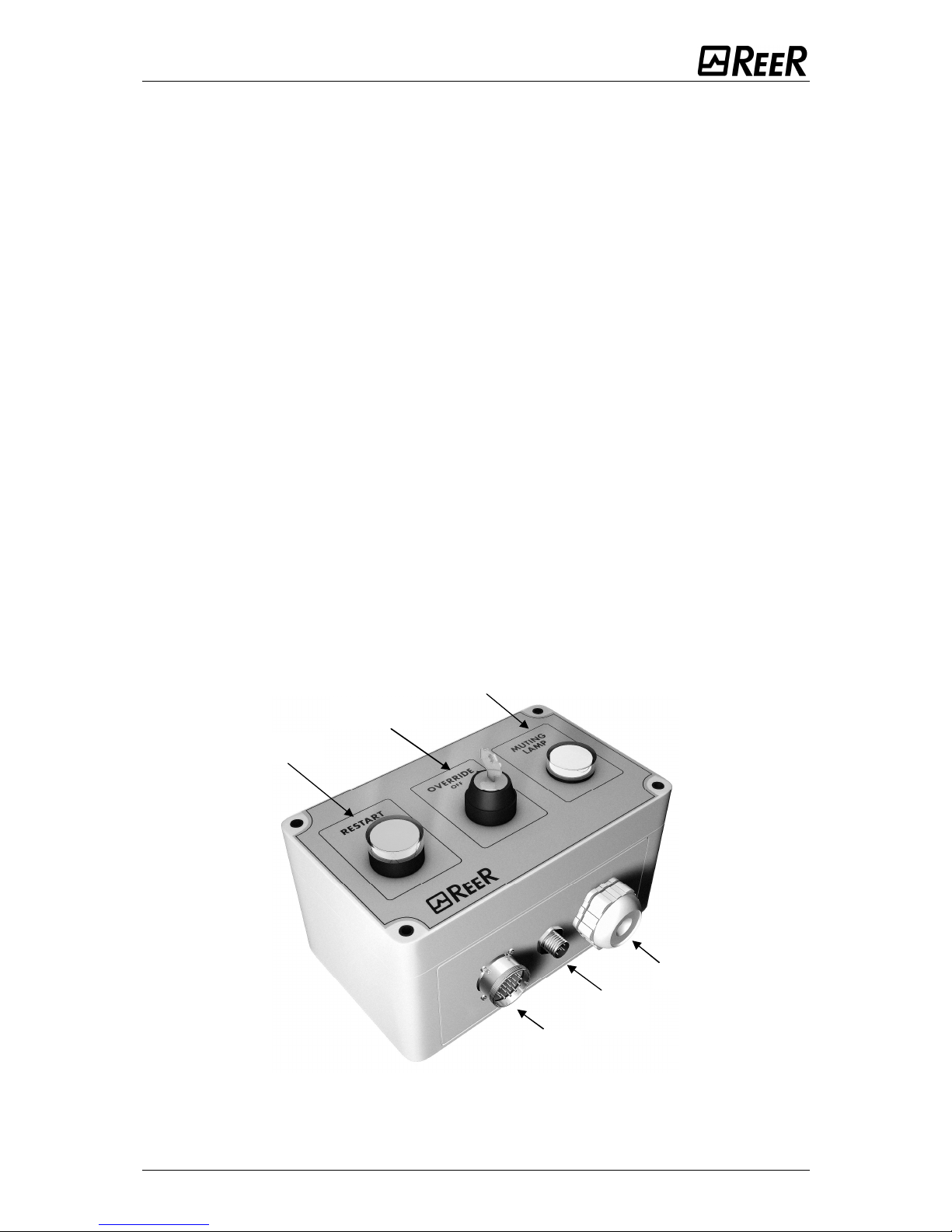
DESCRIPTION
Externally both models have:
1. Connectors for connecting with the light curtain (M23 for RX and M12 for TX).
2. Fairlead for passage of cables towards the machine for:
- power supply;
- connection with output contacts of the internal safety relays and static
outputs of the light curtain;
- Muting enable signals from the outside;
- output signals which indicate the status of the safety light curtain.
The MJB1/MJB3 models also present:
1. Lighted restart button and output status / weak signal led.
2. Key selector switch for Override function.
3. Lamp to signal Muting/Override active.
Figure 1 - MJB1/MJB3
OVERRIDE
KEY
MUTING LAMP /
OVERRIDE
RESTART BUTTON -
OUTPUT STATUS LED
CABLE
FAIRLEAD
RX
TX
(Janus)
Page 2
10 8540705 • 18/12/2012 • Rev.6
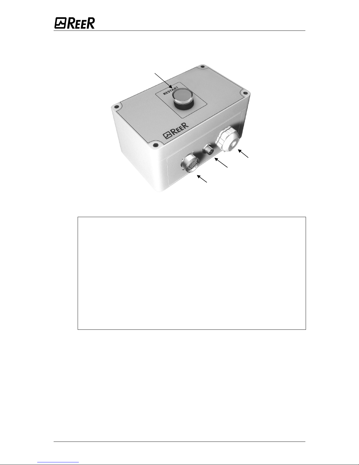
The MJB2 /MJB4 model has:
1. Lighted restart button and output status / weak signal led.
Figure 2 - MJB2/MJB4
It is also possible to match the MJB2 and MJB4 models (without muting
lamp and override command) with muting light curtains as they are fitted
with the required settings.
If connecting an MJB1 or MJB3 model to a JANUS J series safety barrier
(without Muting function), the following connections must be disregarded:
SW1 (pins 1,2,3,4), CJ5, CJ7 (pins 7,8) and CJ9.
For the JANUS, MI, ML, MT versions use of a muting lamp (internal or
external) (0.55W) is obligatory for correct functioning of the light
curtains.
Where the risk analysis of the application requires it, the light curtain
permits connection of an external lamp to signal active Muting (0.55W).
Perform a check of the operation of this lamp periodically verifying its
turning on during the Muting or Override phase.
CABLE
FAIRLEAD
RX
RESTART BUTTON –
OUTPUT STATUS LED
TX
(Janus)
Page 3
8540705 • 18/12/2012 • Rev.6 11
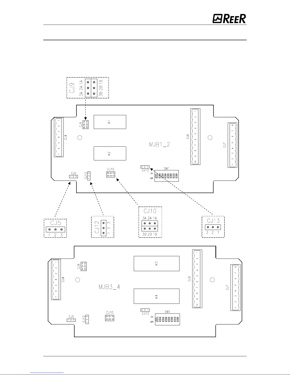
CONFIGURATION
With the aid of the figures of the main board of the single models, the
configuration of the methods of the operating modes is described below.
This configuration is performed, following the descriptions of the following tables,
setting the various jumpers, connectors and dip-switches present on the same
card.
Figure 3 - Models MJB1/MJB2 main board
Figure 4 - Models MJB3/MJB4 main board
Page 4

12 8540705 • 18/12/2012 • Rev.6
SELECTION OF MUTING MODE AND TIMEOUT MUTING (dip-switch SW1)
MI (2 sensors)
MI TRX (2 sensors)
1 2 3 4 5 6 7 8
CONCURRENT
timeout = 30 sec
on
█
see
paragraphs
below
off
█
█ █
1 2 3 4 5 6 7 8
CONCURRENT
timeout = 90 min
on █
see
paragraphs
below
off
█ █ █
MI ("L" logic)
MI TRX ("L" logic)
MM TRX (ML version)
1 2 3 4 5 6 7 8
CONCURRENT
timeout = 30 sec
on
█ █ █
see
paragraphs
below
off
█
1 2 3 4 5 6 7 8
CONCURRENT
timeout = 90 min
on █
█ █
selection pre-
set off
█
MI 4 sensors
MT S4
MI TRX 4 sensors
MT TRX
MM TRX (MT version)
1 2 3 4 5 6 7 8
CONCURRENT
timeout = 30 sec
on
█
see
paragraphs
below
off
█ █ █
1 2 3 4 5 6 7 8
CONCURRENT
timeout =
on
█
see
paragraphs
below
off █ █
█
MI 4 sensors
MT S4
MI TRX 4 sensors
MT TRX S4
MM TRX (MT version)
1 2 3 4 5 6 7 8
Sequential
timeout = 30 sec
on █ █
█
see
paragraphs
below
off
█
1 2 3 4 5 6 7 8
Sequential
timeout =
on █ █ █
see
paragraphs
below
off
█
ML - MT - MLS2
ML TRX
1 2 3 4 5 6 7 8
timeout = 30 sec
on
█
n.c.
see paragraphs
below
off █
1 2 3 4 5 6 7 8
timeout = 90 min
on
█
n.c.
see paragraphs
below
off
█
If a time out limit of 90min is a too short time for a particular machine cycle, the
configuration without time monitoring (t=∞) can be selected. In this case
alternative solutions or additional measures shall be implemented to detected the
condition of a muting function permanently active caused by accumulation of
faults or by the muting sensors activated all the time. For example for the
application of guarding the openings of a conveyor system (palletizers) by
monitoring appropriate signals generated by the transport system to determinate
if and when a pallet is in the detection zone.
Perform a specific risk analysis of the application if the timeout t =
is selected.
Page 5

8540705 • 18/12/2012 • Rev.6 13
MANUAL /AUTOMATIC MODE SELECTION (dip-switch SW1)
ALL MODELS
1 2 3 4 5 6 7 8
Automatic
on
see preceding
paragraph
█
see
par.
below
off
█
ALL MODELS
1 2 3 4 5 6 7 8
Manual
on
see preceding
paragraph
█
see
par.
below
off
█
OTHER CONFIGURATIONS NOT PERMITTED
RANGE AND TEST SELECTION (dip-switch SW1)
JANUS J
JANUS
MI/ML/MT
1 2 3 4 5 6 7 8
Low range *
on
see preceding paragraphs
█
off
█
JANUS J
JANUS MI
1 2 3 4 5 6 7 8
High range *
on
see preceding paragraphs
█
off
█
ALL MODELS
(excluding versions
TRX)
1 2 3 4 5 6 7 8
TEST
on
see preceding paragraphs
off
█ █
OTHER CONFIGURATIONS NOT PERMITTED
* IF TO SELECT THE RANGE OF OPERATION SEL_RANGE1 AND SEL_RANGE2 (PIN 1 and 6
TERMINAL BOARD CJ7) ARE USED, SET DIP 7 and 8 on OFF-OFF (TEST)
* ML/MT MODELS: ALLOWED ONLY THE LOW RANGE SELECTION.
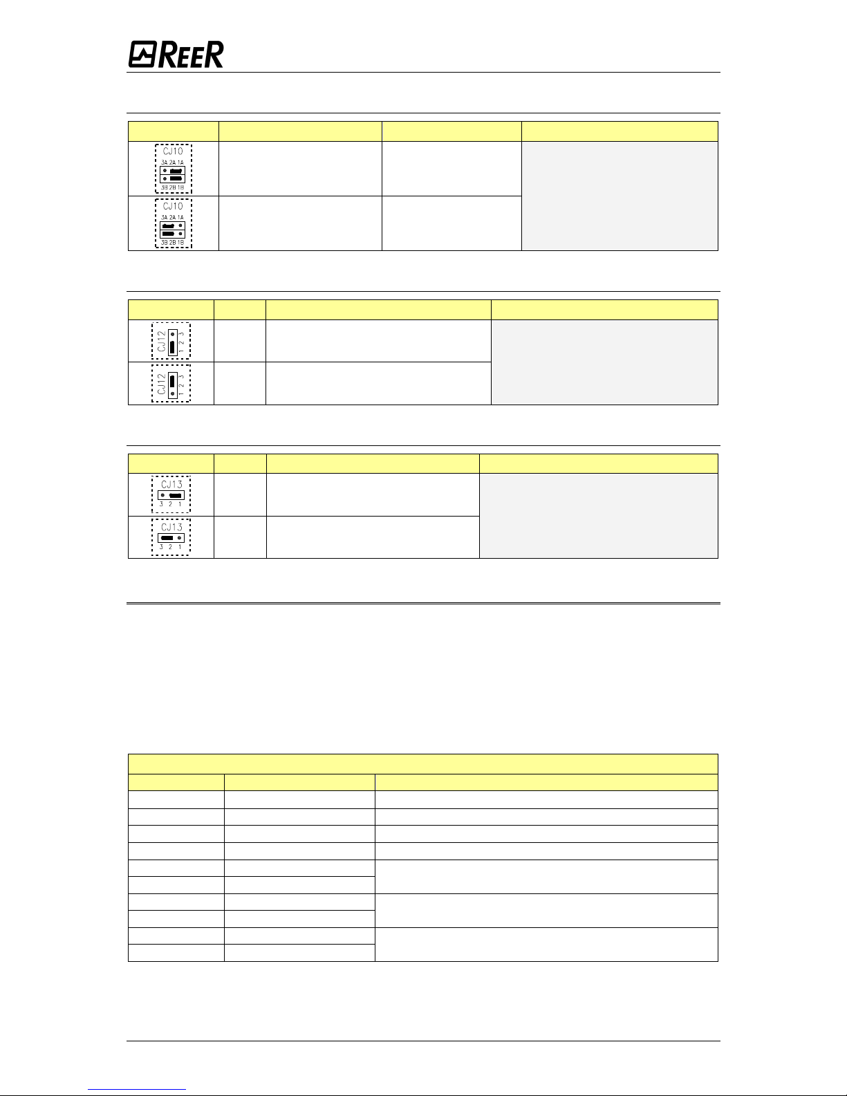
SELECTION OF INTERNAL /EXTERNAL MUTING LAMP
JUMPER PIN DESCRIPTION SELECTION PRESET
1 – 2 External lamp enabled
Internal lamp enabled
2 – 3
Internal lamp enabled
SELECTION TYPE OF OVERRIDE
JUMPER PIN DESCRIPTION SELECTION PRESET
1A – 2A 1B – 2B
Override 1
(with continuous action)
Override 1
(with continuous action)
2A – 3A 2B – 3B
Override 2 (with pulse)
Page 6
14 8540705 • 18/12/2012 • Rev.6
SELECTION STATIC OUTPUTS/RELAYS
JUMPER PIN DESCRIPTION SELECTION PRESET
1A – 2A 1B – 2B Static outputs
Relay
2A – 3A 2B – 3B Relay
READ FEEDBACK ENABLE
JUMPER PIN DESCRIPTION SELECTION PRESET
1 – 2 Read feedback not enabled
Read feedback enabled
2 –3 Read feedback enabled
SELECTION FEEDBACK INTERNAL/EXTERNAL RELAYS
JUMPER PIN DESCRIPTION SELECTION PRESET
1 – 2
Feedback external relays
Feedback internal relays
2 – 3 Feedback internal relays
INSTALLATION AND ELECTRIC CONNECTIONS
The JANUS MJBOX modules can be fixed to the wall, using the proper plastic brackets
inserted in the holes placed on the box rear side corners. These brackets can easily rotate
to reach 90°.
The light curtain must be connected to the respective connectors M23 and M12 (Fig. 1
and 2) using the cables.
The cables coming out from the fairlead (PG21) must be connected - depending on its
utilization - to the connectors CJ6 e CJ7.
Terminal board CJ6
CLAMP NAME DESCRIPTION
1 +24Vdc
24 20%
2 0V 0 Vdc
3 PE Earth clamp
4 SYSTEM STATUS Ref to JANUS instruction manual
5 NA2_B
Ends of the contact normally open n. 2
6 NA2_A
7 NA1_B
Ends of the contact normally open n. 1
8 NA1_A
9 NCB
Ends of contacts normally closed, in parallel
(present only in models MJB3 and MJB4)
10 NCA
Page 7

8540705 • 18/12/2012 • Rev.6 15
Terminal board CJ7
CLAMP NAME DESCRIPTION
1 SEL_RANGE1 Range selection external control
2 EXT LAMP Output of External MUTING lamp (24V; max 5W)
3 OSSD1 Safety static output 1
4 OSSD2 Safety static output 2
5 K1_K2 Input Feedback external relays K1/K2
6 SEL_RANGE2 Range selection external control
7 MUTING_STATUS Output condition of muting function (only for cur. M TRX)
8 MUTING_ENABLE Input of Muting enable (only for cur. M TRX)
Figure 5 - Internal scheme of contacts available on safety relays of MJB1/MJB2 and
MJB3/MJB4
SIGNALS
SIGNAL
MJB1/MJB3 MJB2/MJB4
CONDITION MEANING CONDIZIONE MEANING
OUTPUT STATUS
(Green)
ON Outputs active ON Outputs active
Flashing
Optical signal
received weak *
(Ref. to JANUS
instruction manual)
Flashing
Optical signal
received weak *
(Ref to JANUS
instruction manual)
OFF
Light curtain occupied
: outputs disabled
OFF
Light curtain occupied
: outputs disabled
MUTING
OVERRIDE
(Yellow)
ON
Muting
function (or of
Override) active
OFF Normal functioning
* ACTIVE ONLY WITH JANUS LIGHT CURTAIN
Page 8

16 8540705 • 18/12/2012 • Rev.6
CHARACTERISTICS OF OUTPUT RELAYS
The modules use two guided contacts safety relays (pin 5-6 and 7-8 of CJ6 on
MJB1 and MJB2), (pin 5-6, 7-8 and 9-10 of CJ6 on MJB3 and MJB4), for the output
circuit.
These relays are specified by the manufacturer for voltages and currents greater
than what is indicated in the technical data; nevertheless to guarantee correct
insulation and avoid damage or premature aging, protect each output line with a
3.15 A delayed fuse and verify that the features of the load conform to the
indications on the following table.
MJB1/MJB2 MJB3/MJB4
Number of contacts
2 N.A. 2N.A. - 1N.C.*
Relay category (according to EN60947-5-1)
AC15 / DC13
Max commutable voltage
250Vac, 24Vdc
Min commutable voltage
10Vac/10Vdc
Max commutable current
2A
Min commutable current
10mA@24Vdc
Number of commutations (life)
> 50 x 10
3
(el) / > 40 x 106 (mech)
* 1N.C. = DO NOT USE AS A SAFETY CONTACT
SAFETY DATA
FEEDBACK CONNECTION ACTIVE FEEDBACK CONNECTION MISSING
PFHd SFF MTTFd DCavg PFHd SFF MTTFd DCavg
8,16E-09 99,5% 71,02 99,0% tcycle1
AC15
(6A)
4,60E-07 0,50 71,01738 0 tcycle1
AC15
(6A)
6,78E-10 99,5% 851,50 98,9% tcycle2 4,43E-09 0,52 851,5035 0 tcycle2
4,35E-11 99,2% 13442,07 97,6% tcycle3 9,73E-11 0,69 13442,07 0 tcycle3
1,52E-09 99,5% 378,64 99,0% tcycle1
AC15
(2A)
1,86E-08 0,51 378,6359 0 tcycle1
AC15
(2A)
1,28E-10 99,4% 4523,66 98,5% tcycle2 3,62E-10 0,58 4523,66 0 tcycle2
9,14E-12 99,0% 67522,13 91,9% tcycle3 1,74E-11 0,87 67522,13 0 tcycle3
tcycle1: 300s (one commutation every 5 minutes)
tcycle2: 3600s (one commutation every hour)
tcycle3: one commutation every day
(PFHd according to IEC61508, MTTFd and DCavg according to ISO13849-1)
 Loading...