

Page 1
TYPE 4 SAFETY LIGHT CURTAIN
JANUS
IINNSSTTAALLLLAAZZIIOONNEE,, UUSSOO EE MMAANNUUTTEENNZZIIOONNEE
IINNSSTTAALLLLAATTIIOONN,, UUSSEE AANNDD MMAAIINNTTEENNAANNCCEE
IINNSSTTAALLLLAATTIIOONN,, UUTTIILLIISSAATTIIOONN EETT MMAAIINNTTEENNAANNCCEE
IINNSSTTAALLLLAATTIIOONN,, BBEEDDIIEENNUUNNGG UUNNDD WWAARRTTUUNNGG
IINNSSTTAALLAACCIIÓÓNN,, UUSSOO YY MMAANNTTEENNIIMMIIEENNTTO
O
www.reer.it
Page 2

www.reer.it
8540573 • 16/09/2016 • Rev.20
1
TYPE 4 SAFETY LIGHT CURTAIN
JANUS
SUMMARY
INTRODUCTION ............................................................................................................................................... 3
PRINCIPLE OF OPERATION ........................................................................................................................... 4
LIGHT CURTAIN ............................................................................................................................................ 4
MUTING FUNCTION ..................................................................................................................................... 5
SERIES "ML" - PREASSEMBLED KIT OF JANUS LIGHT CURTAIN AND SENSOR ELEMENT “Ml
S” Integrated Muting sensors – only for one-way openings with pallet exit. ........................................ 5
SERIES "MT" - KIT PREASSEMBLED OF JANUS LIGHT CURTAIN AND SENSORS ELEMENTS
“MT SI” and “MT SE” Integrated Muting sensors – for two-way openings with pallet entrance/exit. .. 6
SERIES "MT S4" - KIT PREASSEMBLED OF JANUS LIGHT CURTAIN AND SENSORS
ELEMENTS “MT S” Integrated Muting sensors – for two-way openings with pallet entrance/exit. .... 6
SERIES "ML S2" - KIT PREASSEMBLED OF JANUS LIGHT CURTAIN AND SENSORS
ELEMENTS “ML S” Integrated Muting sensors – for one-way openings with pallet exit. ................... 7
MODEL "MI" – external sensors 3 selectable methods of Muting. ...................................................... 7
MI models used with “l” operational logic.............................................................................................. 9
INSTALLATION ................................................................................................................................................ 9
POSITIONING .............................................................................................................................................. 11
POSITIONING OF THE MUTING SENSORS ("MI" SERIES). ........................................................... 11
POSITIONING AND ADJUSTMENT OF SENSOR ELEMENTS FOR "ML" and "MT" SERIES: ...... 13
CALCULATION OF THE SAFETY DISTANCE .................................................................................. 14
VERTICAL POSITIONING OF THE LIGHT CURTAIN ....................................................................... 15
MULTIPLE SYSTEMS ........................................................................................................................ 17
DISTANCE FROM REFLECTIVE SURFACES .................................................................................. 17
LIGHT SIGNALS .......................................................................................................................................... 19
Emitter SIGNALS ................................................................................................................................ 19
Receiver SIGNALS ............................................................................................................................. 20
ELECTRICAL CONNECTIONS AND CONNECTORS ................................................................................ 22
EMITTER Connections (Male Connector) ......................................................................................... 22
RECEIVER CONNECTIONS (Main Connector - Male) ...................................................................... 23
Connections CONNECTOR M12 n. 1 (for muting sensor) ("MI" MODELS) (Female Connector) ...... 24
Connections CONNECTOR M12 n. 2 (for muting sensor) ("MI" MODELS) (Female Connector) ..... 24
RECEIVER CONNECTIONS J LR M12 MODELS ............................................................................. 25
SELECTION OF CONFIGURATION AND OPERATING MODE ................................................................. 25
SELECTION FEEDBACK EXTERNAL CONTACTORS K1/K2 .......................................................... 25
SELECTION OF MANUAL/AUTOMATIC FUNCTIONING ................................................................. 26
SELECTION OF THE MAXIMUM DURATION AND TYPE OF MUTING .......................................... 27
OVERRIDE CONFIGURATION .......................................................................................................... 27
MUTING OVERRIDE FUNCTION (“M” MODELS) ............................................................................. 28
"SYSTEM STATUS" OUTPUT (“M” MODELS) .................................................................................. 29
TEST FUNCTION ............................................................................................................................... 29
SAFETY MODULES MJB1 - MJB2 - MJB3 - MJB4 ........................................................................... 29
EXAMPLE OF CONNECTION WITH EXTERNAL CONTACTORS K1/K2 WITH start/restart interlock
activated .............................................................................................................................................. 30
EXAMPLE OF CONNECTION WITH AD SR0 WITH start/restart interlock activated ....................... 31
MUTING STATUS AND LIGHT ("M" MODELS) .............................................................................. 31
CONFIGURATION AND OPERATION MODES J LR M12 ......................................................................... 32
AUTOMATICO MODE ........................................................................................................................ 32
MANUAL MODE ................................................................................................................................. 33
Page 3

2 8540573 • 16/09/2016 • Rev.20
DIMENSIONS .................................................................................................................................................. 34
JANUS "MI" - "J" .......................................................................................................................................... 34
JANUS "ML" ................................................................................................................................................. 35
JANUS "MT" ................................................................................................................................................. 35
JANUS "ML S2" - "MT S4" ........................................................................................................................... 36
TECHNICAL DATA ......................................................................................................................................... 37
CHECKOUTS AND MAINTENANCE ........................................................................................................... 41
TROUBLESHOOTING ................................................................................................................................. 42
ACCESSORIES ........................................................................................................................................... 44
GUARANTEE .................................................................................................................................................. 45
Page 4

8540573 • 16/09/2016 • Rev.20 3
INTRODUCTION
This symbol indicates an important personal safety warning. Failure to comply with the
warning may result in very high risks for exposed personnel.
The JANUS safety light curtain is a multi-beam opto-electronic safety system of the Type 4
category of electro-sensitive devices (in accordance with IEC 61496-1,2; EN 61496-1) – if
necessary equipped with MUTING function (“M” models) - for the protection of persons exposed
to dangerous machines or plants.
The two PNP auto-controlled static outputs permit connection of the light curtain to a control
system complying with the requirements and level of safety required for the application.
The light curtain integrates the start/restart interlock and EDM functions (control of external relays
K1 and K2). In this way, the light curtain can be connected to a simple pair of relays or external
safety contactors without having to install additional modules.
A diagnostic display on the Emitter and Receiver provide the information required for correct use
of the device and to check for any operating faults.
The diagnostic output (see TROUBLESHOOTING, page 42) makes it possible to obtain weak
signal and light curtain status information from a single wire.
JANUS is ideal for protecting:
automatic palletizing/depalletizing systems
materials handling and storage systems;
packing and packaging machines;
assembly lines;
industrial automatic warehouses;
AGV transit openings;
metal, wood, marble and glass tool machines;
presses, die cutting machines.
For problems regarding safety, if necessary, consult the competent safety authorities of
your country or the related industrial association.
For applications in the food industry, consult the manufacturer to check compatibility
between the materials of the light curtain and the chemical agents used.
The guarding function of opto-electronic safety devices is not effective in the case in
which the machine cannot be electrically controlled and is unable to stop the dangerous
movement immediately at any time during the work cycle.
Page 5
4 8540573 • 16/09/2016 • Rev.20
PRINCIPLE OF OPERATION
LIGHT CURTAIN
If the area guarded is clear, the two outputs on the Receiver are active and permit normal
functioning of the machine connected to these.
When an object larger than or equal to the resolution of the system interrupts the sensing field of
one or more beams, the Receiver de-activates its outputs.
This condition makes it possible to block the dangerous movement of the machine (using a
suitable machine stop circuit).
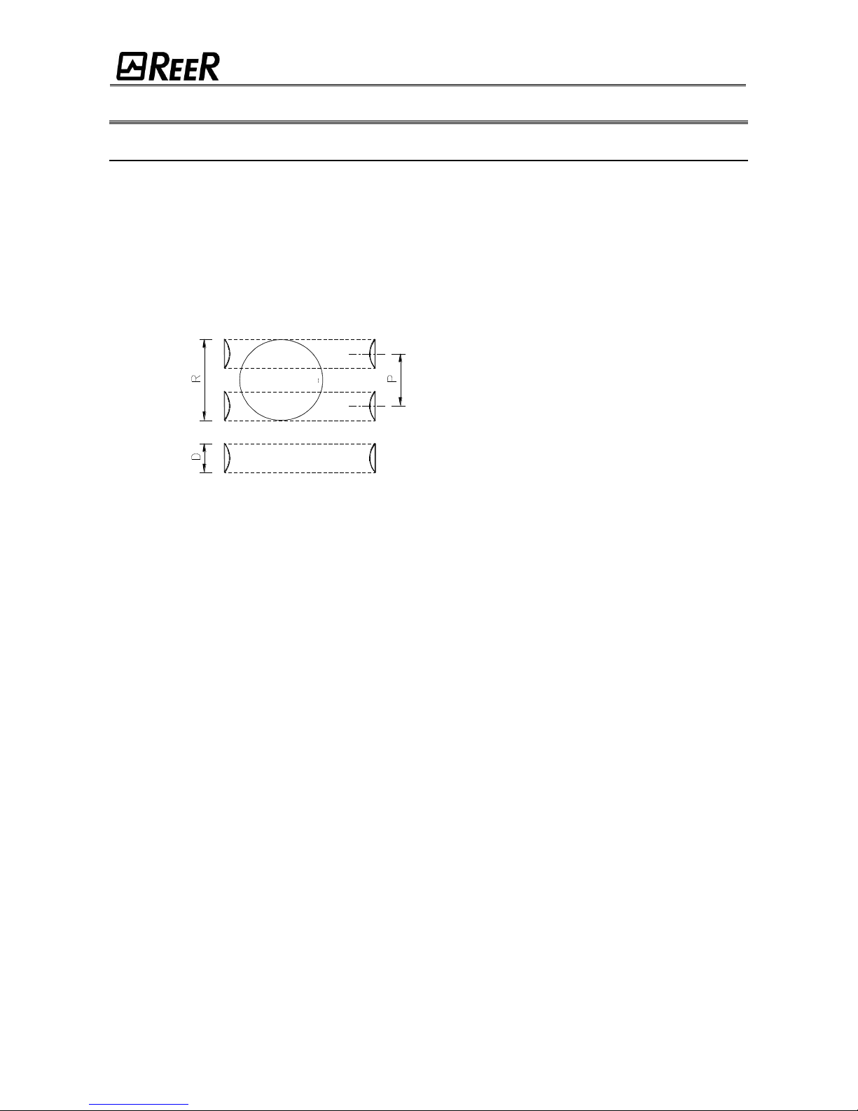
Resolution is the smallest diameter object that will be reliably detected by at least one of the
optical beams generated by the light curtain (Figure 1).
Figure 1- Light curtain resolution
Resolution is constant regardless of working conditions as it depends only on the geometrical
characteristics of the lenses and the center distance between two adjacent lenses. The height of
the guarded area is the height effectively protected by the safety light curtain.
If the curtain is positioned horizontally, this value indicates the depth of the guarded zone. The
useful range is the maximum operating distance that can exist between the Emitter and Receiver.
JANUS is available with the following resolutions (MODEL "MI") :
30mm (protected heights from 300mm to 1200mm) ("MI" models):
PROTECTION OF THE HANDS.
40mm (protected heights from 300mm to 1800mm) (“MI”, "MILR" and “JLR” models):
PROTECTION OF THE HANDS.
90mm (protected heights from 300mm to 1800mm) ("MI" models):
PROTECTION OF THE LIMBS.
JANUS is also available in a Multibeam version ("MI", "MT" and "ML" models) with a pitch
between the lenses of:
500mm (2 beams), 400mm (3 beams), 300mm (4 beams only models "MI"), "MILR"
”J” and “JLR”. PROTECTION OF THE BODY.
P = Pitch bewteen two lenses
D = Diameter of one lens
R = Resolution = P+D
Emitter
Receiver
Opaque Object
Page 6

8540573 • 16/09/2016 • Rev.20 5
MUTING FUNCTION
The Muting function is a temporary suspension of the safety light curtain’s protective
function. Carefully check your risk analysis in order to assess whether the Muting function
is compatible with your application and what additional measures have to be taken.
The Muting function generates a temporary, automatic interruption of safety light curtain
functioning in order to permit normal transit of material through the guarded opening.
The Muting function is activated when the system detects the object that interrupts the opening
protected. In other words, when the system recognizes the material and distinguishes between
this and any operator (in a potentially dangerous situation), it is enabled to bypass the light
curtain temporarily, allowing the material to pass through the opening.
The Muting sensors – which can be integrated in the light curtain (models "ML" and "MT") or be
external (model "MI") – form the sensing system that decides whether the Muting function is to
be activated (or not). Control of the dangerous opening can be de-activated only by a correct
sequence of interruption of the beams of the Muting sensors.
The JANUS system is available in the “ML" and "MT” models (with 2 integrated opto-electronic
sensors) and "MI" models to which 2 or 4 sensors of various type can be connected (proximity,
optical, capacitive etc).
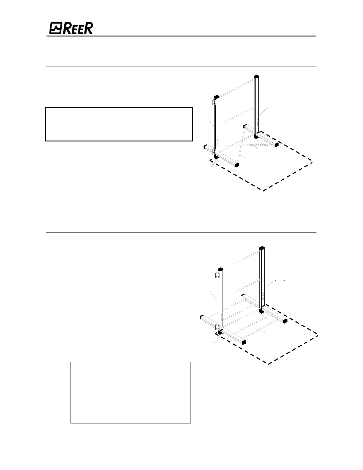
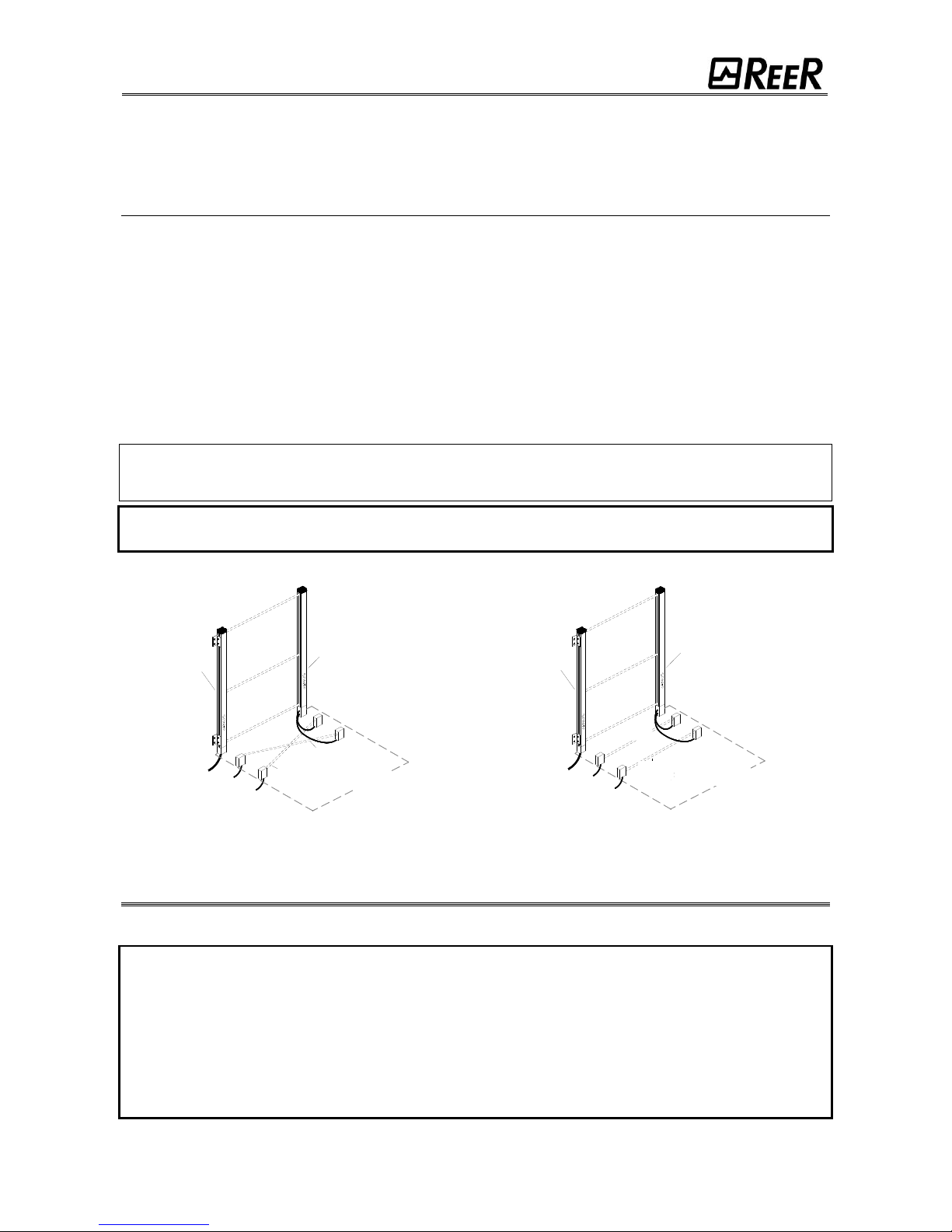
SERIES "ML" - PREASSEMBLED KIT OF JANUS LIGHT CURTAIN AND SENSOR ELEMENT “ML S”
Integrated Muting sensors – only for one-way openings with pallet exit.
In this model, the sensors 1 and 2 are on the same side of
the vertical light curtain and are placed in front of the
guarded opening (Figure 2).
This model is one-way and is useful for protecting pallet exit
openings.
The Muting function is activated following concurrent
interruption (within max. 4 sec) of sensors S1 and S2. The
Muting function remains active as long as both sensors
remain occupied.
When the first of the 2 sensors is cleared, the material has
four seconds to abandon the guarded area delimited by the
light curtain. The Muting condition will be disabled as soon
as the protected area is cleared.
After 4 seconds, if the light curtain is still occupied, the
OSSD outputs are disabled, interrupting functioning of the
machine. For this model, the maximum duration of the
Muting condition (timeout) can be set to 30 seconds or 90
minutes.
To guarantee the safety operation of the ML
series, the horizontal muting sensor must be
mounted INSIDE the dangerous area
(dashed on Figure 2).
When using a ML series JANUS, the minimum
distance between two consecutive pallet must
be less than 10cm or more than 32cm.
Figure 2
Emitter
Receiver
Sensor 1
Sensor 2
DDAANNGGEERROOUUSS
AARREEA
A
Page 7
6 8540573 • 16/09/2016 • Rev.20
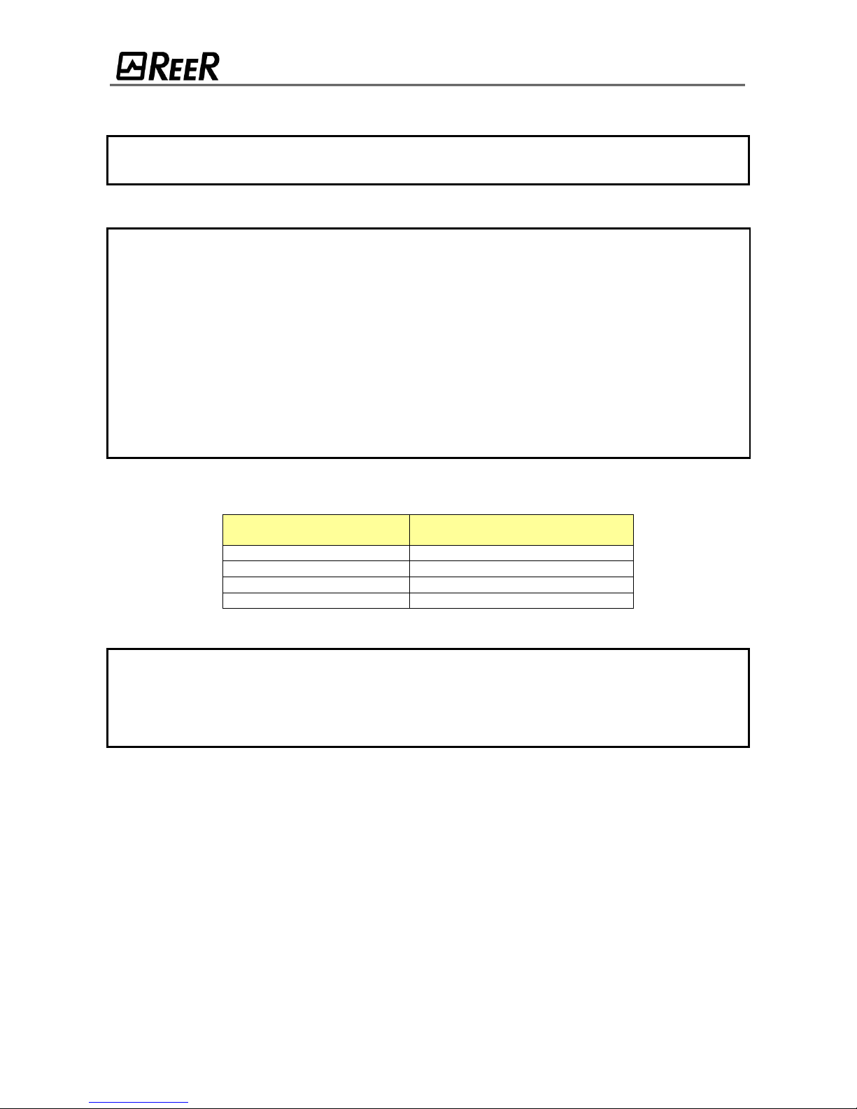
SERIES "MT" - KIT PREASSEMBLED OF JANUS LIGHT CURTAIN
AND SENSORS ELEMENTS “MT SI” and “MT SE”
Integrated Muting sensors – for two-way openings with pallet entrance/exit.
In this model, the Muting sensors are the first on one side
and the second on the other in relation to the vertical light
curtain (Figure 3).
This model is therefore two-way and is useful for
protecting pallet entrance/exit openings.
The point of intersection of the two muting
sensors (Figure 11) must be inside the
dangerous area in order to avoid accidental
actuation of the Muting function.
The Muting function is activated following concurrent
interruption (within max. 4 sec) of sensors S1 and S2.
The Muting function remains active as long as both
sensors remain occupied.
When the first of the two sensors is cleared, the Muting
function is disabled.
Also for this model, the maximum duration of the Muting
condition (timeout) can be set to 30 seconds or 90
minutes.
Figure 3
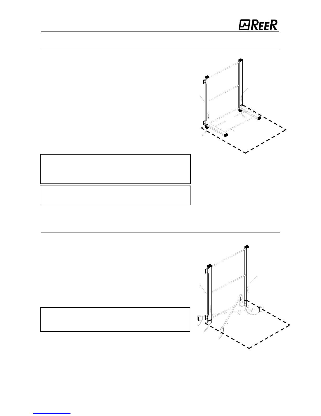
SERIES "MT S4" - KIT PREASSEMBLED OF JANUS LIGHT CURTAIN AND SENSORS ELEMENTS “MT S”
Integrated Muting sensors – for two-way openings with pallet entrance/exit.
This model is two-way and is useful for protecting pallet
entrance/exit openings (Figure 4).
Using this model, two methods of operation are possible:
Concurrent
The Muting function is activated following concurrent
interruption of sensors S1 and S2 (within maximum
4sec) (or S4 and S3 with material transiting in the
opposite direction). Muting status ends after clearing
of the opening and of S3 (or S2 with material
transiting in the opposite direction).
Sequential
The Muting function is activated following sequential
interruption of sensors S1 and S2, of the opening and of
sensors S3 and S4. It is important to remember that,
for correct actuation of the Muting function, the
sequence indicated in Figure 8 and Table 1 is
required (without time restrictions).
The MT S4 models have two
available timeouts: 1) 30 sec;
2) infinite (Sequential operation).
The pallet minimum length (in both
operation modes) must be 70cm (all
the 4 sensors have to be
simultaneously occupied).
Figure 4
Emitter
Receiver
Sensor 1
Sensor 2
Sensor 3
Sensor 4
DDAANNGGEERROOUUSS
AARREEA
A
Emitter
Receiver
Sensor 1
Sensor 2
DDAANNGGEERROOUUSS
AARREEA
A
Page 8
8540573 • 16/09/2016 • Rev.20 7
SERIES "ML S2" - KIT PREASSEMBLED OF JANUS LIGHT CURTAIN AND SENSORS ELEMENTS “ML S”
Integrated Muting sensors – for one-way openings with pallet exit.
In this model, the sensors 1 and 2 are on the same side of the
vertical light curtain and are placed in front of the guarded opening
(Figure 5).
This model is one-way and is useful for protecting pallet exit
openings.
The Muting function is activated following concurrent interruption
(within max. 4 sec) of sensors S1 and S2. The Muting function
remains active as long as both sensors remain occupied.
When the first of the 2 sensors is cleared, the material has four
seconds to abandon the guarded area delimited by the light curtain.
The Muting condition will be disabled as soon as the protected area
is cleared.
After 4 seconds, if the light curtain is still occupied, the OSSD
outputs are disabled, interrupting functioning of the machine. For
this model, the maximum duration of the Muting condition (timeout)
can be set to 30 seconds or 90 minutes.
To guarantee the safety operation of the ML S2
series, the horizontal muting sensor must be
mounted INSIDE the dangerous area (dashed in
Figure 5).
When using a ML series JANUS, the minimum distance
between two consecutive pallet must be 40cm.
Figure 5
MODEL "MI" – external sensors
3 selectable methods of Muting.
The "MI" model can use 2 or 4 sensors that must be connected to
the M12 connectors on the front part of the vertical light curtain.
These sensors may be of various types (proximity, optical,
capacitive with PNP or electromechanical type output and with
DARK-ON switching (i.e. output active when material is present).
If 4 sensors are connected, it is possible to choose two methods of
operation: 1) Concurrent; 2) Sequential.
CONNECTION WITH 2 EXTERNAL SENSORS (Figure 6)
This model is two-way and is useful for protecting pallet
entrance/exit openings.
The point of intersection of the two sensors must be
located inside the dangerous area to prevent accidental
and dangerous activation of the Muting function.
The Muting function is activated following concurrent interruption
(within max. 4s) of sensors S1 and S2. The Muting function
continues as long as both sensors are occupied. When the first of
the two sensors is cleared, the Muting function is disabled.
Also for this model, the maximum duration of the Muting condition
(timeout) can be set to 30 seconds or 90 minutes.
Figure 6
Receiver
Emitter
Sensor 2
Sensor 1
DDAANNGGEERROOUUSS
AARREEA
A
Emitter
Receiver
Sensor 1
Sensor 2
DDAANNGGEERROOUUSS
AARREEA
A
Page 9

8 8540573 • 16/09/2016 • Rev.20
CONNECTION WITH 4 EXTERNAL SENSORS
Using 4 sensors, two methods of operation are possible:
Sequential (figure 7)
The Muting function is activated following sequential interruption of
sensors S1 and S2 and of sensors S3 and S4. It is important to
remember that, for correct actuation of the Muting function,
the sequence indicated in Figure 8 and Table 1 is required
(without time restrictions).
It is also possible to enable a control of the activation time of the 4
sensors.
Concurrent
The Muting function is activated following concurrent interruption
of sensors S1 and S2 (within maximum 4sec) (or S4 and S3 with
material transiting in the opposite direction).
Muting status ends after clearing of the opening and of S3
(or S2 with material transiting in the opposite direction).
The MI models connected with 4 external
sensors, have two available timeouts:
1) 30 sec; 2) infinite.
Figure 7
sensor1
sensor2
sensor3
sensor4
Muting
Figure 8
Sequential muting: activation sequence.
SENSOR 1
SENSOR 2
SENSOR 3
SENSOR 4
LIGHT CURTAIN STATUS
0 0 0
0
LIGHT CURTAIN ACTIVE
1 0 0
0
LIGHT CURTAIN ACTIVE
1 1 0 0 MUTING
1 1 1 0 MUTING
1 1 1 1 MUTING
0 1 1 1 MUTING
0 0 1 1 MUTING
0 0 0
1
LIGHT CURTAIN ACTIVE
0 0 0
0
LIGHT CURTAIN ACTIVE
Table 1
LEGEND:
0 = SENSOR FREE; 1 = SENSOR ENGAGED
SENSOR 1
SENSOR 2
SENSOR 3
SENSOR 4
MUTING
ENGAGED
CLEAR
Emitter
Receiver
Sensor 4
Sensor 3
Sensor 2
Sensor 1
Page 10
8540573 • 16/09/2016 • Rev.20 9
Both operating modes with 4 sensors are TWO-WAY.
The correct Muting sequence can start either from sensor 1 or from sensor 4.
MI MODELS USED WITH “L” OPERATIONAL LOGIC
In this model the sensors 1 and 2 are on the same side with respect to the vertical curtain and are positioned
in front of the dangerous opening (Figure 9 and Figure 10). This model is unidirectional and is useful for
protecting openings with pallet exit.
The activation of the Muting function takes place following the simultaneous interruption (within max. 4 sec)
of sensors S1 and S2. The Muting function remains while both sensors are occupied.
On release of the first of the 2 sensors, the material will still have 4 seconds available to abandon the
protected area delimited by the curtain. The Muting condition will be disabled as soon as the protected area
is released.
If the curtain is still occupied after the 4 seconds, the OSSD outputs are disabled, interrupting machine
functioning.
For this model, the maximum duration of the Muting condition (timeout) can be selected in 30 seconds or 90
minutes (Table 13).
It is indispensable that a Muting sequence is completed (release of controlled area) in order to
guarantee the correct activation of the successive sequence.
For safe functioning of the MI series (with L logic), it is necessary that the muting sensors
are positioned inside the dangerous area (traced in Figure 9 and Figure 10).
Figure 9 - Crossed sensors
Figure 10 - Parallel sensors
INSTALLATION
Before installing the JANUS safety system, check that:
The safety system is used only as stopping device and not as machine control device.
The machine can be controlled electrically.
Any dangerous action of the machine can be promptly interrupted. In particular, the
stopping time of the machine must be known, if necessary measure this.
The machine must not cause dangerous situations due to flying or dropping of material;
otherwise, additional mechanical guards are required.
The minimum size of the object that must be detected must be greater than or equal to the
resolution of the model selected.
DDAANNGGEERROOUUSS
AARREEA
A
Emitter
Receiver
Sensor 2
Sensor 1
DDAANNGGEERROOUUSS
AARREEA
A
Emitter
Receiver
Sensor 2
Sensor 1
Page 11
10 8540573 • 16/09/2016 • Rev.20
Knowing the shape and dimensions of the dangerous area, it is possible to assess the width and
height of its access area:
Compare these dimensions with the maximum useful range and the height of the area
protected of the model used.
Before positioning the safety device, take into account the following general indications:
Check that the temperature of the environments where the system is installed is
compatible with the temperature operating parameters indicated in the technical data.
Do not position the Emitter and Receiver close to sources of bright light or high intensity
flashing lights.
Particular environmental conditions may impair the detection efficiency of light curtains. In
places with the possibility of mist, rain, fumes or dust, for correct functioning of the
equipment it is advisable to apply suitable correction factors Fc to the values of useful
operating range.
In these cases:
Pu = Pm x Fc
where Pu and Pm are respectively the useful and maximum operating range in meters.
The recommended Fc factors are indicated in the table below.
ENVIRONMENTAL
CONDITION
CORRECTION FACTOR Fc
Mist
0,25
Vapors
0,50
Dust
0,50
Dense fumes
0,25
Table 2
If the device is installed in areas liable to sudden changes in temperature, suitable
measures must be taken in order to avoid formation of condensation on the lenses which
could impair detection efficiency.
If JANUS light curtains are used with palletizers, depalletizers and stacking/destacking
machines for empty pallets, refer to European standard EN 415-4.
Page 12
8540573 • 16/09/2016 • Rev.20 11
POSITIONING
Protection of the guarded opening by JANUS must be integrated with suitable mechanical
guards.
While the "MI" model permits various types of installation (2, 4 sensors, one- or two-way), the
"ML" and "MT" have been designed for "dedicated" use.
In particular, "ML" manages the muting function in one-way mode (normally for
pallet exit); in this case, the horizontal arms must be positioned between the
dangerous area and the light curtain.
The "MT" model manages the muting function in two-way mode using four horizontal
arms. This model is useful when the pallets, once the process has been carried out
by the dangerous machine, must be returned outside using the same palletizer.
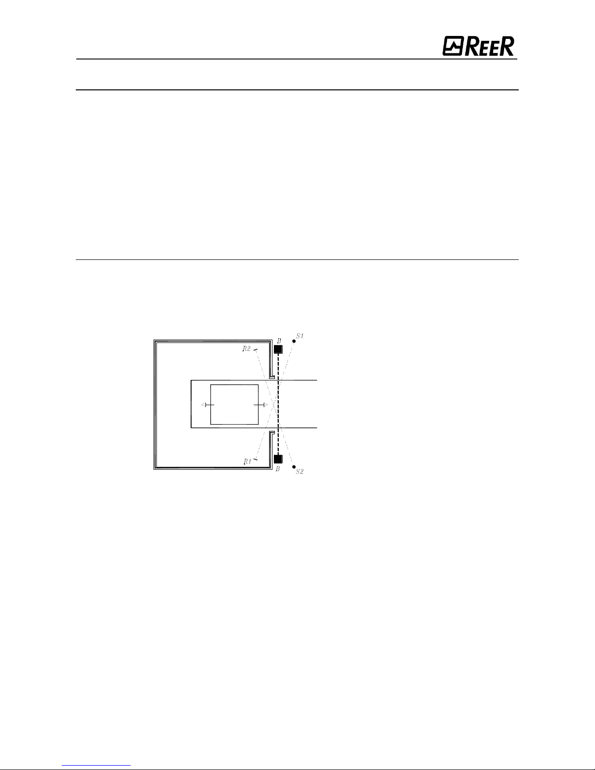
POSITIONING OF THE MUTING SENSORS ("MI" SERIES).
2 sensors
The Emitter and receiver of the light curtain must be positioned so as to permit access to the
dangerous area from above, from below and from the sides without first of all intercepting at least
one of the optical beams.
Indications for correct positioning of the light curtain are provided in the figure below.
Figure 11
For correct positioning of sensors 1 and 2, i.e. those that manage enabling and disabling of the
Muting function, take into account the following:
the two beams must be crossed and pass diagonally through the zone guarded by
the light curtain;
the point of intersection of the two beams must be in the dangerous area beyond
the light curtain;
the angle between the two Muting beams must be calculated according to the size of
the pallet and its speed, taking into account that the Muting function is activated only
if the interception delay between the two sensors is less than 4 seconds;
the pallet must interrupt the two beams before intercepting the light curtain;
the two beams must be interrupted continuously by the pallet for the entire period
during which the pallet passes between the sensors;
make sure that the two beams are effectively intercepted by the material on the pallet
and not by the empty pallet;
the zone identified by the points of interception and clearing of the beams of sensors
1 and 2 by pallet must be limited as far as possible (or suitably protected) so as
S1 = Sensor 1
S2 = Sensor 2
R1 = Reflector 1 (or Receiver 1)
R2 = Reflector 2 (or Receiver 2)
B = Light curtain
Material
Dangerous area
Page 13
12 8540573 • 16/09/2016 • Rev.20
to avoid the possibility of accidental passing through the light curtain with Muting
active (Figure 12).
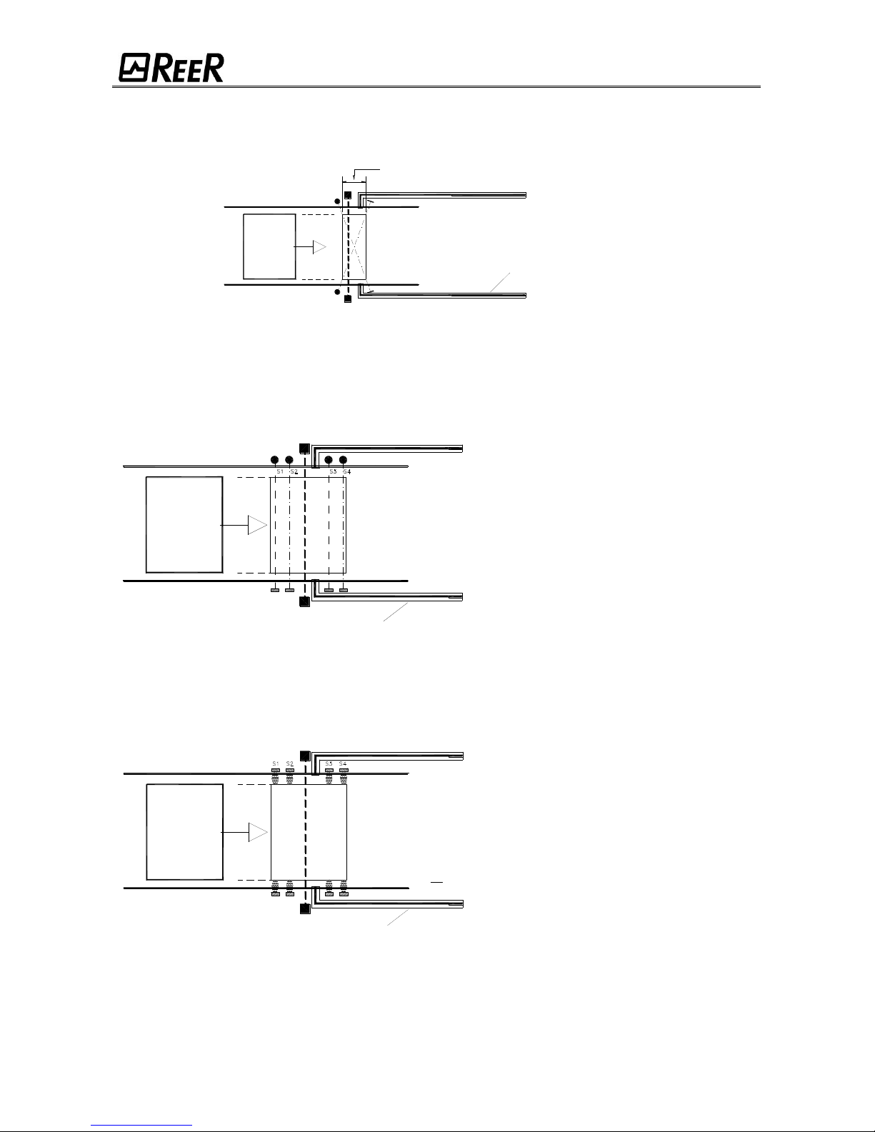
Figure 12
4 sensors
For correct positioning of sensors 1, 2, 3 and 4, i.e. those that manage enabling and disabling of the
Muting function, take into account the following:
Figure 13
SEQUENTIAL (Figure 8, Figure 13 Table 1):
the distance between the first and the
last sensor must never exceed the length
of the pallet (in one of the phases of
the sequence, the 4 sensors must all
be intercepted simultaneously);
the pallet must interrupt sensors S1 and
S2 (or S4 and S3 in the opposite
direction) before intercepting the light
curtain;
make sure that the two beams are
intercepted by the material on the pallet
and not by the empty pallet
Figure 14
CONCURRENT (Figure 14):
The Muting function is activated following
concurrent interruption (within max. 4
sec) of sensors S1 and S2 (or S4 and
S3 in the opposite direction).
also in this operating mode, for correct
activation of the Muting function, for a
short period of time, all 4 sensors
must be intercepted simultaneously.
Dimension to be reduced to a minimum
Mechanical guards
Material
DANGEROUS
AREA
Mechanical guards
DANGEROUS
AREA
Material
Mechanical guards
DANGEROUS
AREA
Material
Page 14
8540573 • 16/09/2016 • Rev.20 13
POSITIONING AND ADJUSTMENT OF SENSOR ELEMENTS FOR "ML" AND "MT" SERIES:
As already mentioned, the pre-assembled JANUS "ML" and "MT" kit consist of a vertical light
curtain and of one ("ML" series) or two ("MT" series) horizontal sensor element in which the
Muting sensors are integrated.
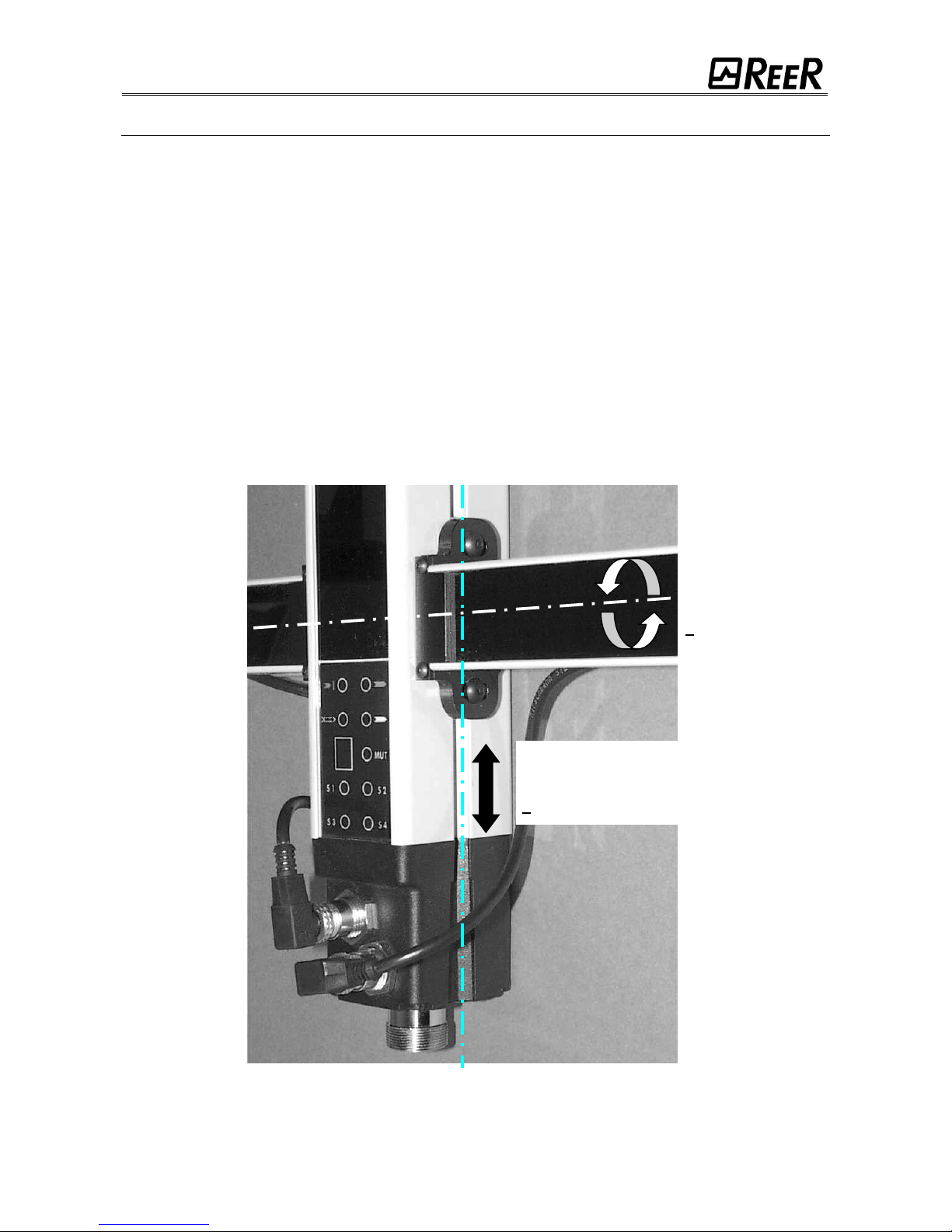
The system is equipped with a VERTICAL adjustment of the sensor elements to solve the
following problems:
Incorrect and non-continuous sensor beam interception by the material in movement.
Need to reduce the beam intensity when transparent objects (i.e. glass, plastic, etc)
are detected.
At the operating range limits (1 ÷ 2,5m) or in dusty environments, it would be necessary to use
the ANGULAR adjustment to reach the maximum signal intensity. (REER advise against this
operation with transparent materials).
Figure 15 shows the two axes (horizontal and vertical) on which to operate.
To make the adjustment:
loosen the Allen screws;
operate on the arms to make the adjustments;
tighten the Allen screws.
Figure 15
NOTE: For installations that do not require any particular adjustments, the ML and MT
models are pre-aligned and do not require further regulation.
MAXIMUM VERTICAL
ADJUSTMENT
PERMITTED:
+ 70mm
MAXIMUM
ANGULAR
ADJUSTMENT
PERMITTED:
+ 8°
Page 15
14 8540573 • 16/09/2016 • Rev.20
CALCULATION OF THE SAFETY DISTANCE
The light curtain must be positioned at a distance exceeding or equal to the minimum safety
distance S so that a dangerous point can be reached only after stopping the dangerous action of
the machine (Figure 16).
Referring to European standard EN999, the minimum safety distance S must be calculated
according to the following formula:
S = K (t1 + t
2
) + C
where:
S
minimum safety distance
mm
K
speed of approach of the body to the danger area.
mm/sec
t1
total response time in seconds of the safety light curtain
sec
t2
response time of the machine in seconds, i.e. the time taken by the machine
to interrupt the dangerous action from the moment in which the stop signal is
transmitted
sec
C
additional distance
mm
Failure to comply with the safety distance reduces or defeats the protective function of the
light curtain.
If the position of the light curtain does not exclude the possibility of the operator
accessing the danger area without being detected, the system must be equipped with
additional mechanical guards.
Figure 16
Page 16

8540573 • 16/09/2016 • Rev.20 15
VERTICAL POSITIONING OF THE LIGHT CURTAIN
Models with resolution 30, 40mm.
These models are suitable for detecting the hands
The minimum safety distance S is calculated according
to the following formula:
S = 2000 (t1 + t2) + 8(D-14)
(D=resolution)
This formula is valid for distances S between 100 and
500 mm. If, according to the calculation, S exceeds 500
mm, the distance can be reduced up to a minimum of
500 mm using the following formula:
S = 1600 (t1 + t2) + 8 (D-14)
Where, due to the particular configuration of the
machine, it is possible to access the danger area from
above, the highest beam of the light curtain must be at a
height H of at least 1800 mm from the resting surface G
of the machine.
Figure 17
Models with resolution 90mm.
These models are suitable for detecting the arm or legs
and must not be used to detect the fingers or hands.
The minimum safety distance S is calculated according
to the following formula:
S = 1600 (t1 + t2) + 850
In any case, the height H of the highest beam
from the reference surface G must not be less
than 900 mm while the height of the lowest
beam P must not exceed 300 mm.
Figure 18
Light
curtain
Dangerous
point
Reference surface
Direction
of approach
Light
curtain
Dangerous
point
Direction
of
approach
Reference surface
Page 17

16 8540573 • 16/09/2016 • Rev.20
Mutlibeam Models
These models are suitable only for detection of the
entire body.
The minimum safety distance S is calculated
according to the following formula:
S = 1600 (t1 + t2) + 850
The recommended height H from the
reference surface G (ground) is as follows:
Figure 19
MODEL
BEAMS
Recommended height H
(mm)
2B
3B
4B
2
3
4
400 – 900
300 – 700 – 1100
300 – 600 – 900 - 1200
For applications on packaging machines (palletizers and depalletizers), comply with the
indications of European standard EN 415-4, which are repeated below.
Figure 20
Protection of the opening with JANUS light curtain and mechanical side guards.
From low level (floor)
Device with minimum 3 beams
Above the conveyor (roller bed)
Device with minimum 2 beams
Type of access
Dimensions in m
Light
curtain
Dangerous point
Direction
of
approach
Reference surface
Page 18

8540573 • 16/09/2016 • Rev.20 17
MULTIPLE SYSTEMS
When several JANUS systems are used, these must not interfere optically with each other.
Position the elements so that the beam emitted by the Emitter of a system is received only by the
respective Receiver.
Figure 21 provides various examples of correct positioning of two photo-electric systems.
Incorrect positioning could generate interference and possibly result in irregular functioning.
Figure 21
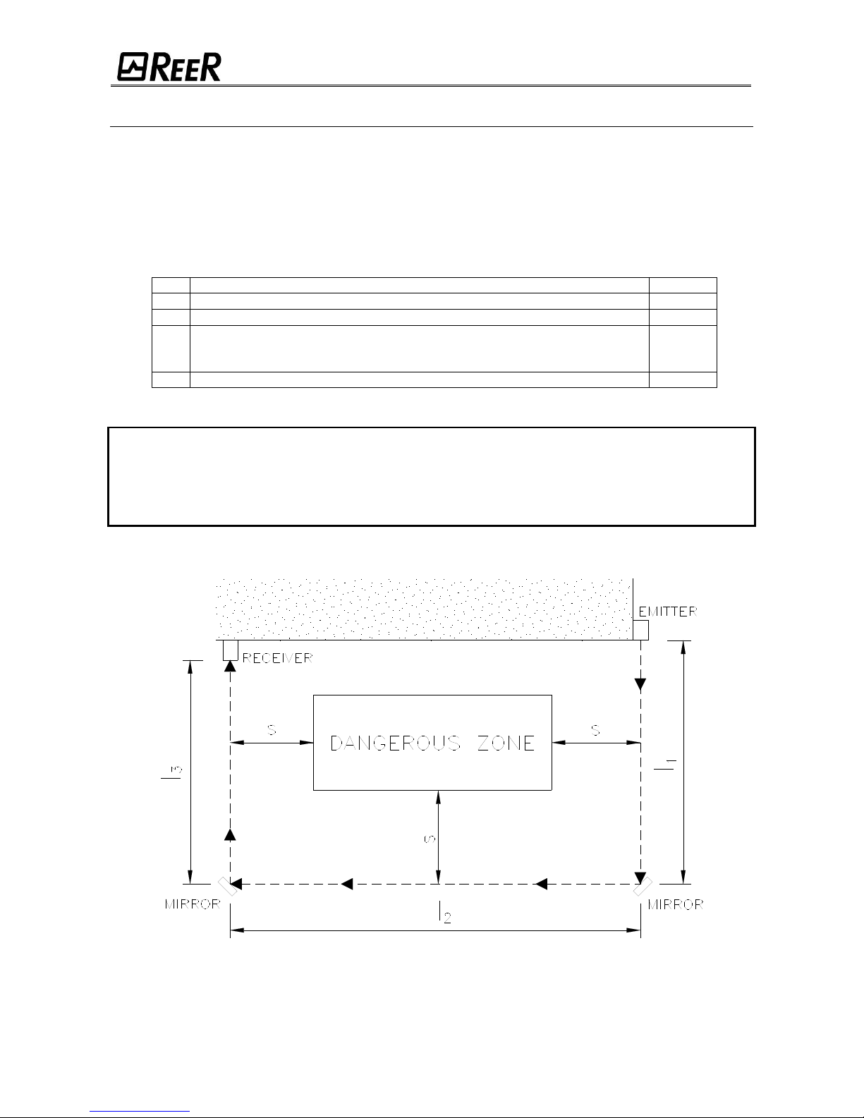
DISTANCE FROM REFLECTIVE SURFACES
The presence of reflective surfaces close to the light curtain may cause spurious reflections that
prevent detection. Referring to Figure 22, object A is not detected because of surface S which,
reflecting the beam, closes the sensing field between the Emitter and Receiver. A minimum
distance d must therefore be maintained between any reflective surfaces and the protected area.
The minimum distance d must be calculated according to the distance l between Emitter and
Receiver and taking into account that the angle of projection and reception is equal to 4º.
Figure 22
Figure 23 indicates the values of the minimum distance d to be complied with as the distance l
between Emitter and Receiver varies.
Side by side systems: A
Adjacent positoning of the
two projectors
Systems one above the other: B
Emitter
Receiver
Direct beam
Reflected beam
Page 19

18 8540573 • 16/09/2016 • Rev.20
Figure 23
After installation, check for any reflective surfaces, intercepting the beams first of all at the center
and those close to the Emitter and Receiver.
During this procedure, the red led on the Receiver must never switch off.
SENSITIVE AREA
EMITTER
RECEIVER
JANUS
JANUS Long Range
Page 20

8540573 • 16/09/2016 • Rev.20 19
LIGHT SIGNALS
EMITTER SIGNALS
At power-on, all the leds are ON for a period of 5 seconds.
Subsequently, the leds display functioning condition.
"ML" - "MT" MODELS "J"-"LR"-"MI" MODELS
Figure 24
LED
MEANING NORMAL
FUNCTIONING (LED ON)
COLOR
Test
Light curtain under test
YELLOW
Light curtain functioning
GREEN
Fault detected
RED High range selected *
ORANGE
Table 3
If a fault is detected, the led will indicate the type of alarm (ref. "TROUBLESHOOTING").
* The value of the selected range depends on the JANUS model. (Refer TECHNICAL DATA - page 31).
RANGE
Page 21

20 8540573 • 16/09/2016 • Rev.20
RECEIVER SIGNALS
At power-on, for a period of 5 seconds, the display will show the number "8" and all the leds will
be ON. In the next 10 seconds, the display and the leds will show the configuration selected. At
initial power-on after installation, always check the accuracy of these settings very carefully.
This check is also indispensable in all cases of malfunctioning (ref. "TROUBLESHOOTING").
During display of the configuration, the display will show the letter "C" while during normal
functioning, a hyphen "-" will be displayed.
Initial display
(JANUS “M”) (JANUS “J”)
Figure 25
JANUS “M”
LED
INITIAL CONFIGURATION
COLOR
(LED ON)
(LED OFF)
S1
Enabling of timeout 30s
Enabling of timeout 90min
YELLOW
S2
With 4 sensors, enabling of
Sequential muting
With 4 sensors, enabling
of concurrent op. mode
YELLOW
S3
Manual functioning mode
enabled
Automatic functioning
mode enabled
YELLOW
S4
Control of feedback
external relays enabled
Control of feedback
external relays disabled
YELLOW
MUT
Muting configuration
with 4 sensors
Muting configuration
with 2 sensors
YELLOW
Weak (1)
-
-
ORANGE
Break (2)
OSSD outputs set to OFF
-
RED
Guard (3)
-
-
GREEN
Clear/Override (4)
Push button override
Spring return key override
YELLOW
JANUS “J”
Weak (1)
-
-
ORANGE
Break (2)
OSSD outputs set to OFF
-
RED
Guard (3)
-
-
GREEN
Clear (4) CLEAR
-
-
YELLOW
MAN/AUTO
Manual functioning
mode enabled
Automatic functioning
mode enabled
YELLOW
EN EDM
Control of feedback
external relays enabled
Control of feedback
external relays disabled
YELLOW
Table 4
2
1
3
4
2
1
3
4
Page 22

8540573 • 16/09/2016 • Rev.20 21
Normal display
Figure 26
JANUS “M”
LED
NORMAL FUNCTIONING
COLOR
(LED ON)
(LED OFF)
S1
Interruption Sensor 1
Sensor 1 clear
YELLOW
S2
Interruption Sensor 2
Sensor 2 clear
YELLOW
S3
Interruption Sensor 3
Sensor 3 clear
YELLOW
S4
Interruption Sensor 4
Sensor 4 clear
YELLOW
MUT
Muting active *
Light curtain active
YELLOW
Weak (1)
Weak signal received
Signal received OK
ORANGE
Break (2)
Light curtain occupied,
OSSD outputs set OFF
-
RED
Guard (3)
Light curtain clear,
OSSD outputs set ON
-
GREEN
Override_1 (3)
Light curtain in override,
OSSD outputs set ON **
-
Clear (4)
Light curtain clear, OSSD
outputs set OFF (the receiver
is waiting for a Restart signal)
-
YELLOW
Override_2 (4)
Override request
(BLINKING LED)
-
* The Muting/Override lamp lights on.
** A small "o" letter appears on the display and at the same time the external Muting/Override lamp blinks.
JANUS “J”
Weak (1)
Weak signal received
Signal received OK
ORANGE
Break (2)
Light curtain occupied,
OSSD outputs set OFF
-
RED
Guard (3)
Light curtain clear,
OSSD outputs set ON
-
GREEN
Clear (4) CLEAR
Light curtain clear, OSSD
outputs set OFF (the receiver
is waiting for a Restart signal)
-
YELLOW
Table 5
In case of fault, only the red led will remain ON and the display will show a flashing "C" or “F” followed by
the fault code (ref. TROUBLESHOOTING paragraph).
2
1
3
4
2
1
3
4
Page 23

22 8540573 • 16/09/2016 • Rev.20
ELECTRICAL CONNECTIONS AND CONNECTORS
Caution
Before making the electrical connections, always check that the voltage available matches that
indicated in the technical data.
The Emitter and Receiver must be powered at 24Vdc±20%.
The external power supply must comply with EN 60204.
The electrical connections must be made according to the diagrams provided in this manual.
In particular, never connect other devices to the connectors of the Emitter and Receiver.
To assure dependable functioning, using a diode bridge power supply unit, its output capacity
must be at least 2000F for each Ampere absorbed.
EMITTER CONNECTIONS (Male Connector)
MOD
PIN
COLOR
NAME
TYPE
DESCRIPTION
FUNCTIONING
"ML"
- "MT"
1
Brown
24VDC
IN
24Vdc power supply
Protected with 2A fuse
2
White
TEST
IN
External test command
+24VDC : LIGHT CURTAIN ACTIVE
0VDC : LIGHT CURTAIN IN TEST
STATUS
3
Blue
0VDC
IN
0Vdc power supply
-
4
Black
N.C.
-
-
-
5
Grey
PE
-
Ground connection
-
If the TEST command is not used, connect pin 2 of the connector to +24 VDC permanently.
MOD
PIN
COLOR
NAME
TYPE
DESCRIPTION
FUNCTIONING
"J"
- "LR"
- "MI"
1
Brown
24VDC
IN
24Vdc power supply
Protected with 2A fuse
2
White
SEL
RANGE/TEST1
IN
INPUT1 for range/test
selection
see table "RANGE and TEST
SELECTION"
3
Blue
0VDC
IN
0Vdc power supply
-
4
Black
SEL
RANGE/TEST2
IN
INPUT2 for range/test
selection
see table " RANGE and TEST
SELECTION"
5
Grey
PE
-
Ground connection
-
RANGE and TEST SELECTION ("J"-"LR"-"MI" models)
PIN 2
PIN 4
MEANING
+24 Vdc
0 Vdc *
LOW range (Refer TECHNICAL DATA - page 31)
0 Vdc *
+24 Vdc
HIGH range (Refer TECHNICAL DATA - page 31)
0 Vdc *
0 Vdc *
EMITTER IN TEST CONDITION
+24 Vdc
+24 Vdc
Condition not allowed
* (0 Vdc or open circuit)
Table 6
5 2 1
3
4
Page 24

8540573 • 16/09/2016 • Rev.20 23
RECEIVER CONNECTIONS (Main Connector - Male)
Make sure the M23 connector is screwed down tightly to ensure correct barrier operation! (4 turns)
PIN
COLOR
NAME
TYPE
DESCRIPTION
FUNCTIONING
* 1
White
MUT. LAMP
OUT
Muting lamp output
24VDC with Muting
active
2
Red
OSSD2
OUT
Safety outputs
24VDC with :
Light curtain clear
Muting active
Muting Override
3
Grey
OSSD1
OUT
4
Yellow
STATUS
OUT
Weak signal condition
+ OSSD status
ref. Figure 28
5
Green
N.C. - -
-
6
Blue
0VDC
0Vdc power supply
-
* 7
Violet
CONF0
IN
Configuration
of Muting characteristics
ref. Table 12
Table 13
* 8
Pink
CONF1
IN
* 9
Grey-Pink
CONF2
IN
* 10
Red-Blue
CONF3
IN
11
White-Green
ENABLE_K
IN
Enabling of external contactor
control
ref. Table 10
12
Black
PE
Ground connection
-
13
White-Yellow
MAN/AUTO
IN
Manual / Automatic mode
selection
ref. Table 11
14
Yellow-Brown
RESTART
IN
Restart
Active on LO-HI
transition (min.
duration of the signal
400 msec)
15
White-Grey
N.C.
* 16
Grey-Brown
OVERRIDE1
IN
Override signals
ref. Table 14
* 17
White-Pink
OVERRIDE2
IN
18
Brown-Green
FEED_K1K2
IN
Feedback external contactors
ref. Table 10
19
Brown
24VDC
24Vdc power supply
Table 7
* Connection present only in “M” models (with MUTING function)
Page 25

24 8540573 • 16/09/2016 • Rev.20
CONNECTIONS CONNECTOR M12 n. 1 (FOR MUTING SENSOR) ("MI" MODELS) (Female Connector)
PIN
COLOR
NAME
TYPE
DESCRIPTION
FUNCTIONING
1
Brown
24 VDC
OUT
Power supply sensors 1 and 3
Positive
2
White
SENSOR 1
IN
Input SENSOR 1
< 5VDC : SENSOR FREE
11÷30 VDC : SENSOR ACTUATED
3
Blue
0 VDC
OUT
Power supply sensors 1 and 3
Negative
4
Black
SENSOR 3
IN
Input SENSOR 3
< 5VDC : SENSOR FREE
11÷30 VDC : SENSOR ACTUATED
5
Grey
PE
-
-
-
Table 8
CONNECTIONS CONNECTOR M12 n. 2 (FOR MUTING SENSOR) ("MI" MODELS) (Female Connector)
PIN
COLOR
NAME
TYPE
DESCRIPTION
FUNCTIONING
1
Brown
24 VDC
OUT
Power supply sensors 2 and 4
Positive
2
White
SENSOR 2
IN
Input SENSOR 2
< 5VDC : SENSOR FREE
11÷30 VDC : SENSOR ACTUATED
3
Blue
0 VDC
OUT
Power supply sensors 2 and 4
Negative
4
Black
SENSOR 4
IN
Input SENSOR 4
< 5VDC : SENSOR FREE
11÷30 VDC : SENSOR ACTUATED
5
Grey
PE
-
-
-
Table 9
In the "ML" and "MT" series, the M12 connectors of the receiver must be connected only to the
sensors integrated in the horizontal arms provided with the system.
5 1 2 4 3
5 1 2 4 3
Page 26

8540573 • 16/09/2016 • Rev.20 25
RECEIVER CONNECTIONS J LR M12 MODELS
Figure 27
PIN
COLOR
NAME
TYPE
DESCRIPTION
OPERATION
2
Brown
24VDC
-
24VDC power supply
-
7
Blue
0VDC - 0VDC
-
8
Red
PE - Ground connection
-
1
White
OSSD1
OUTPUT
Safety static outputs
PNP active high
3
Green
OSSD2
OUTPUT
5
Grey
EXT_SEL_A
INPUT
Barrier configuration
According the normative
EN61131-2
6
Pink
EXT_SEL_B
INPUT
4
Yellow
EXT_K1_K2
INPUT
Feedback external contactors
SELECTION OF CONFIGURATION AND OPERATING MODE
The inputs of the JANUS light curtain receiver make it possible to configure various operating
modes. At power-on, for correct functioning, the various inputs must be connected as
indicated below.
SELECTION FEEDBACK EXTERNAL CONTACTORS K1/K2
Feedback of the external contactors K1/K2 is enabled at system power-on (as indicated
in Table 10). If this function is enabled, the set of N.C. contacts of the external relays must be
connected to pin 18 of the receiver. The voltage level of this input must be:
+24VDC with OSSD static outputs de-activated.
0VDC with OSSD static outputs activated.
+24VDC
18
11
RX
K1 K2
0VDC
Page 27

26 8540573 • 16/09/2016 • Rev.20
CONTROL OF
EXTERNAL
CONTACTORS
K1/K2
Receiver pins
MEANING
PIN 11
PIN 18
24VDC 0 Control disabled
0
K1 K2
Control enabled
0
0
Not permitted
24VDC
24VDC
Not permitted
Table 10
SELECTION OF MANUAL/AUTOMATIC FUNCTIONING
Manual or automatic operating mode can be set through connection of pins 13 and 14 of the
connector of the receiver.
In AUTOMATIC functioning, the two static outputs OSSD1 and OSSD2 follow the
status of the guarded opening. With the area guarded clear, the outputs will supply
+24VDC, while with the area occupied they will supply 0VDC. Refer to Table 10 and
Table 11 for correct configuration of operating mode.
In MANUAL functioning, the two static outputs OSSD1 and OSSD2 are active only
with the danger area clear and after the light curtain has received a correct RESTART
signal. This command must be sent on pin 14 of the receiver and is active with a
0VDC ---> +24VDC transition.
The minimum duration of the RESTART command must be 100ms.
Use of manual mode (start/restart interlock activated) is compulsory if the safety device
controls an opening to protect a danger area and a person, after passing through the
opening, may remain in the danger area without being detected (use as 'trip device'
according to IEC 61496). Failure to comply with this rule may result in very serious
hazards for the persons exposed.
The Restart control must be installed outside the danger area in a position where the
danger area and the entire work area concerned are clearly visible. It must not be possible
to reach the control from inside the danger area.
SELECTION OF MANUAL/AUTOMATIC FUNCTIONING
CONNECTIONS
AUTOMATIC
JANUS RECEIVER
MANUAL
JANUS RECEIVER
PIN 13
PIN 14
NOT PERMITTED
0
0
24VDC
24VDC
Table 11
Page 28

8540573 • 16/09/2016 • Rev.20 27
SELECTION OF THE MAXIMUM DURATION AND TYPE OF MUTING
The inputs of the JANUS light curtain receiver make it possible to configure the various types of
Muting available and the maximum duration of the Muting condition (timeout).
At power-on, for correct functioning, the various inputs must be connected as indicated below.
Model
Receiver pin
Timeout
selected
10 (CONF3)
9 (CONF2)
"MT"
0
24VDC
t1
24VDC
0
t2
"ML"
"ML S2"
0
24VDC
t1
24VDC
0
t2
Table 12 - Models with 2 sensors
where: t1 = 30 sec; t2 = 90 min
NOTE: For the MT (with 2 sensors) and ML models, pin 7 and 8 must not be connected.
Model
Receiver pin
Timeout
selected
MEANING
10 (CONF3)
9 (CONF2)
8 (CONF1)
7 (CONF0)
"MI"
(2 sensors)
0
24VDC
0
0
t1
Concurrent mode
(within 4sec)
24VDC
0 0 0
t2
"MI" with
“L” logic
0
24VDC
24VDC
24VDC
t1
24VDC
0
24VDC
24VDC
t2
"MI"
(4 sensors)
"MT S4"
0 0 0
24VDC
t1
Concurrent mode
(within 4sec)
0
0
24VDC
0
infinite
24VDC
24VDC
0
24VDC
t1
Sequential mode
24VDC
24VDC
24VDC
0
infinite
Table 13 - Models MI and models MT with 4 sensors
where: t1 = 30 sec; t2 = 90 min
OVERRIDE CONFIGURATION
Receiver pin
MEANING
16 (OVERRIDE1)
17 (OVERRIDE2)
0 0 Selection override with spring return key
0
24VDC
Selection override with push button (switch)
24VDC
0
Not permitted
24VDC
24VDC
Not permitted
Table 14
Page 29

28 8540573 • 16/09/2016 • Rev.20
MUTING OVERRIDE FUNCTION (“M” MODELS)
The OVERRIDE function must be used when the machine stops due to incorrect Muting
activation sequences with the material obstructing the guarded opening.
In this situation, the OSSD outputs are not active as the light curtain and/or at least one Muting
sensor is occupied. In this condition the OVERRIDE request led blinks (ref.Table 5).
This function activates the OSSD outputs making it possible to remove the material that is
obstructing the opening concerned; moreover the Muting lamp lights on.
Throughout the entire phase during which the OVERRIDE function is active, the
OVERRIDE/MUTING light is ON. Check efficiency of this light periodically (during the Muting
or Override phases).
Warning!! The Override with pulse command automatically activates the outputs of the light
curtain until both the light curtain and the muting sensors are free of obstacles again. During
this period, the light curtain is unable to protect access to the guarded opening. Therefore, all
operations must be carried out under the strict supervision of expert personnel.
The operator will use the Override mode previously selected (ref. Table 14).
1. Override with continuous action command
2. Override with pulse command
Override with continuous action command
This function is activated driving pins 16 and 17 of the receiver to +24VDC at the same time
(maximum delay = 400ms) using a 2-way key selector with spring return;
PIN 16
PIN 17
CONDITION
0 0 Normal operation
24VDC
24VDC
OVERRIDE request
The maximum override duration is 15 minutes; it can be stopped for two different causes.
When the selector is released or if the 15 minutes has been elapsed, override
ends, de-activating the OSSD outputs, turning off the muting lamp and showing
normal condition on the display. A new override condition can be started, releasing
and rearming the selector.
Once the opening has been cleared and the sensors are free again, override
ends and GUARD condition (light curtain in normal operation) is activated without
necessity of further commands.
Override with pulse command
This function is activated inverting (maximum delay = 400ms) the condition of pin 16 and 17 of
the receiver using a push button (switch). During the override the 16 and 17 are not controlled.
PIN 16
PIN 17
CONDITION
0
24VDC
Normal operation
24VDC 0 OVERRIDE request
The override condition can last a maximum of 15 minutes (repeatable).
The function can only be re-started by pressing the pushbutton again (subject to the following
conditions) :
1. Maximum total OVERRIDE time (after n consecutive requests) = 60 min
2. Maximum number of consecutive requests for OVERRIDE = 30.
The override condition ends when the barrier and sensors are cleared (entrance clear) and the
GUARD condition is re-enabled (barrier fully operational) without sending any further commands.
The timer (point 1) and counter (point 2) are reset when one of the following conditions occurs:
A correct muting sequence.
A system reset (switched off and then turned on).
Page 30

8540573 • 16/09/2016 • Rev.20 29
"SYSTEM STATUS" OUTPUT (“M” MODELS)
A signal that makes it possible to detect 2 separate items of information is available on pin 4 of
the receiver:
1. Weak signal arriving from the Emitter;
2. Status of the OSSD outputs.
The output signal will be set to one (24 Vdc) or zero (according to the status of the
OSSD) if the weak signal condition is not present
The output signal will be at one (24 Vdc) or zero with impulses towards 0 V or
towards 24 in weak signal conditions.
The conditions of the signal concerned are summarized in the figure below:
Figure 28
TEST FUNCTION
By means of the test function, which simulates occupation of the protected area, it possible to
verify the operation of the entire system by means of an external supervisor (e.g. PLC, control
module, etc.). The JANUS barrier system features an automatic self-diagnosis function that
enables it to detect response time malfunctions (this time is declared for each model).
This safety system is permanently active and does not require any interventions from the outside.
The TEST function is available should the user wish to check equipment connected downstream
of the barrier (without physically entering the protected area). By means of this function the
OSSDs can be switched from ON to OFF as long as the function remains active. Please see
Table 6 for details about the use of the test function.
The minimum duration of the TEST function must be 40 msec.
SAFETY MODULES MJB1 - MJB2 - MJB3 - MJB4
JANUS light curtain can be integrated by the safety modules MJB1 - MJB2 - MJB3 and MJB4.
In fact they contain terminal boards, pre-wired connection, dip switches for the configuration
choice and two safety relays connected to the light curtain outputs.
MJB1 - MJB3 operates with Janus M (muting) and has: RESTART push button,
key selector for the Muting OVERRIDE, muting function active signaling lamp and two
safety relays.
MJB2 - MJB4 operates with Janus J (without muting) and has: RESTART push
button and two safety relays.
OSSD outputs de-activated and
indication of weak signal de-activated.
OSSD outputs active and indication of
weak signal de-activated.
OSSD outputs de-activated and
indication of weak signal active.
OSSD outputs active and indication of
weak signal active.
15 45ms
800ms
Page 31

30 8540573 • 16/09/2016 • Rev.20
EXAMPLE OF CONNECTION WITH EXTERNAL CONTACTORS K1/K2 WITH START/RESTART INTERLOCK ACTIVATED
K1
K2
PE
Figura 29
In order to assure a correct barrier operation, it is necessary to connect the pins 2 and
4 of the Emitter according to table 6 (page 20) and to the "TEST FUNCTION" paragraph of
page 26. For correct operation (in the case of JANUS "M" without the use of Muting) the
muting light must be connected (pin 1) and the Muting mode must be configured correctly
(pin 7-8-9-10) following the indications in Table 13.
“M” MODELS
(With Muting)
“J” MODELS
(Without Muting)
Page 32

8540573 • 16/09/2016 • Rev.20 31
EXAMPLE OF CONNECTION WITH AD SR0 WITH START/RESTART INTERLOCK ACTIVATED
Figura 30
In the protected area clear condition, the Receiver supplies a voltage of 24VDC on both
outputs. The required load must therefore be connected between the output terminals and
the 0DVC (Figure 31).
Figure 31
MUTING STATUS AND LIGHT ("M" MODELS)
Muting status must be highlighted to the outside using a indicator light close to the
guarded opening.
JANUS is equipped with an output (pin 1 of connector M23 on the receiver) to which the indicator
light can be connected and is able to monitor correct functioning of this and also that it is present.
For a JANUS "M" light curtain correct operation the muting lamp must be connected. When using
JANUS "M" without Muting function or Muting lamp, connect the receiver pin 1 to 0VDC (via a 10KΩ
(1/4 W) resistor). If the muting lamp has a malfunction, the curtain switches to stop status indicating
a FAIL on the display of the receiver.
Page 33

32 8540573 • 16/09/2016 • Rev.20
CONFIGURATION AND OPERATION MODES J LR M12
The JANUS J LR M12 operation mode is selected realizing appropriate connections on the M12
8 poles of the active element (Table 15 and Table 16).
AUTOMATICO MODE
In this operation mode the OSSD1 and OSSD2 safety outputs follow the barrier status :
with proteceted area clear, the safety outputs are active.
with proteceted area intercepted, the safety outputs are disabled.
CONNECTION
OPERATION MODE
EXT_SEL_A (PIN 5)
connected to :
ext_OSSD1 (PIN 1)
EXT_SEL_B (PIN 6)
connected to :
ext_OSSD2 (PIN 3)
EXT_K1_K2 (PIN 4)
connected to :
0VDC
AUTOMATIC without
K1-K2 feedback
EXT_SEL_A (PIN 5)
connected to :
ext_OSSD2 (PIN 3)
EXT_SEL_B (PIN 6)
connected to :
ext_OSSD1 (PIN 1)
EXT_K1_K2 (PIN 4)
connected to : 24VDC
(through series of contatcts
N.C. of external relays)
AUTOMATIC with
K1-K2 feedback
Table 15
Example of connection of J LR M12 barrier in
AUTOMATIC mode with feedback K1K2
Example of connection of J LR M12 barrier in
AUTOMATIC mode without feedback K1K2
Page 34

8540573 • 16/09/2016 • Rev.20 33
MANUAL MODE
In this operating mode the safety outputs OSSD1 and OSSD2 are activated (+24VDC) only if the protected
area is free and after the reception of the RESTART signal, using a push button or thank to an appropriate
control on the SEL_A or SEL_B input (ref.Table ).
After an interception of the protected area, the safety outputs will be de-activated.
To re-activate them it will be necessary to repeat the sequence described above.
The RESTART command is active with a voltage of +24VDC.
The minimum duration of the RESTART command is 400ms.
Use of manual mode (start/restart interlock activated) is compulsory if the safety device
controls an opening to protect a danger area and a person, after passing through the
opening, may remain in the danger area without being detected (use as 'trip device'
according to IEC 61496). Failure to comply with this rule may result in very serious
hazards for the persons exposed.
CONNECTION
OPERATION MODE
EXT_SEL_A (PIN 5)
connected to :
24VDC (PIN 2)
EXT_SEL_B (PIN 6)
connected to :
24VDC (PIN 2)
(through the RESTART
pushbutton)
EXT_K1_K2 (PIN 4)
connected to :
0VDC
MANUALE senza
feedback K1-K2
EXT_SEL_A (PIN 5)
connected to :
24VDC (PIN 2)
(through the RESTART
pushbutton)
EXT_SEL_B (PIN 6)
connected to :
24VDC (PIN 2)
EXT_K1_K2 (PIN 4)
connected to : 24VDC
(through series of contatcts
N.C. of external relays)
MANUALE con
feedback K1-K2
Table 16
Example of connection of J LR M12 barrier in
MANUAL mode with feedback K1K2
Example of connection of J LR M12 barrier in
MANUAL mode without feedback K1K2
Page 35

34 8540573 • 16/09/2016 • Rev.20
DIMENSIONS
The following tables shows the dimensions of the different JANUS models; refer to the drawings of pages 34 ÷ 36.
"J" MODELS
DIMENSION
16m RANGE
LR
2B
3B
4B
600
900
1200
2B
3B
4B
A (TX - RX)
736
1036
1136
736
1036
1336
736
1036
1136
B (Protected Area)
- - -
610
910
1210 - -
-
C
(First beam position)
120
76
"MI" MODELS
DIMENSION
16m RANGE
LR
300
450
600
750
900
1050
1200
1350
1500
1650
1800
2B
3B
4B
2B
3B
4B
A (TX)
436
586
736
886
1036
1186
1336
1486
1636
1786
1936
736
1036
1136
736
1036
1136
A (RX)
476
626
776
926
1076
1226
1376
1526
1676
1826
1976
776
1076
1176
776
1076
1176
B
(Protected Area)
310
460
610
760
910
1060
1210
1360
1510
1660
1810 - - - - - -
C
(First beam position)
72
120
76
MODELS "ML" - "MT"
DIMENSION
2B
3B
A (TX - RX)
776
1076
C (First beam position)
120
JANUS "MI" - "J"
Figure 32
C: POSITION OF THE 1st ACTIVE BEAM
TX (MODELS "MI / J")
TX/RX (MODELS "J LRM12")
RX
Fastening:
Models with A<1050 2 brackets LL with 2 inserts
Models with A>1050 3 brackets LL with 3 inserts
Page 36

8540573 • 16/09/2016 • Rev.20 35
JANUS "ML"
Figure 33
JANUS "MT"
Figure 34
RX
RX
Dimension
ML
D
330
E
300
F
50
Dimension
MT
D
230 E 330 F 200 G 300
Page 37

36 8540573 • 16/09/2016 • Rev.20
JANUS "ML S2" - "MT S4"
Figure 35
Figure 36 - Fastening brackets LL
Figure 37 - Fastening inserts FI
Dimension
ML S2 / MT S4
D
370 E 334 F 84
(Present on MT S4
models only)
Page 38

8540573 • 16/09/2016 • Rev.20 37
TECHNICAL DATA
GENERAL DATA
Safety category
4
Response time
ms
30
Reset
automatic or manual selectable
Power supply
Vdc
24 20%
Connections
Emitter M12 – 5 pins (male)
Receiver M12 – 8 pins (male)
Receiver M23 – 19 pins (male)
* Muting sensors M12 – 5 pins (female)
Protection rating
IP 65
Max. length of
electrical connections
m
100
Dimensions light curtain section
mm
50 x 60
Operating temperature
°C
-10 55
Max operative humidity
%
95
Safety outputs
2 PNP auto-controlled – 500 mA @ 24 Vdc
with short-circuit, overload, reversal of polarity protection
Max. output current
mA
500
Max. capacitive load
F
2,2
Max. off-state voltage
V
< 1
Max. resistance of connections between
OSSDs and the loads
Ohm
< 25
Light curtain status and
weak signal outputs
PNP – 100 mA at 24 Vdc
Max. consumption
W
3 (Emitter)
6 (Receiver)
* Max current to Muting sensors
(only MI models)
mA
100
* Muting lamp output
24Vdc / 0,5 5 W
* Response time on
Muting signals (sensors)
ms
100
* Muting max. time-out models ML -
ML S2 - MT - MI with 2 sensors
30 sec or 90 min (selectable)
* Muting max. time-out
models MI with 4 sensors - MT S4
30 sec or excludible (selectable)
* Override max. time-out
min
15 (renewable)
Light curtain lifetime
20 years
Safety level
Type 4
IEC 61496-1:2004
IEC 61496-2:2006
SIL 3
IEC 61508:1998
SILCL 3
IEC 62061:2005
PL e - Cat.4
ISO 13849-1 : 2006
* Specifications applicable only to models with Muting function
MI SERIES
Heights of guarded areas
mm
310 ÷ 1810 for light curtains with a resolution of 40 and 90 mm
310 ÷ 1210 for light curtains with a resolution of 30 mm
Resolution of light curtains for
detecting upper or lower limbs
mm
30 – 40 - 90
Number of beams of light curtains for
detection of body in access control
2 – 3 – 4
Operating range Low / High
m
0 ÷ 6 / 1 ÷ 16
Muting system
two-way with 2 or 4 sensors with max. concurrent time of 4 sec
two-way sequential with 4 sensors
Muting sensors
external with relay or PNP output
Page 39

38 8540573 • 16/09/2016 • Rev.20
ML SERIES
PRE-ASSEMBLED KIT OF JANUS LIGHT CURTAIN AND SENSOR ELEMENT “ML S”
Number of beams
2 – 3
Operating range
m
1 ÷ 2,5
0 ÷ 2 (ML S2 models)
Muting system One-way with max. concurrent actuation time 4 sec
Muting sensors 2 opto-electronic - integrated – pre-aligned– prewired
Muting sensor detection plane adjustable height and slope
MT SERIES
PRE-ASSEMBLED KIT OF JANUS LIGHT CURTAIN AND SENSOR ELEMENTS “MT SI” AND “MT SE”
Number of beams
2 – 3
Operating range
m
1 ÷ 2,5
0 ÷ 2 (MT S4 models)
2 ÷ 3,5 (MT H models)
Muting system Two-way with 2 (MT - MT H) or 4 (MT S4) sensors
Muting sensors
2 (MT - MT H) or 4 (MT S4)
opto-electronic - integrated – pre-aligned– prewired
Muting sensor detection plane adjustable height and slope
MT / ML / MT S4 / ML S2 SERIES
2B
3B
Number of beams
2
3
Distance between beams mm
500
400
Response time ms
7
7
Overall barrier ht. mm
776
1076
PFHd *
7,53E-09
7,70E-09
DCavg
#
97,94%
97,99%
MTTFd
#
years
100
CCF
#
80%
MI series
Resolution 30 mm
303
453
603
753
903
1053
1203
Number of beams
16
24
32
40
48
56
64
Response time ms
12
15
18
21
24
27
30
Overall barrier ht. mm
476
626
776
926
1076
1226
1376
PFHd *
9,06E-09
9,98E-09
1,09E-08
1,18E-08
1,28E-08
1,37E-08
1,46E-08
DCavg
#
98,24%
98,35%
98,44%
98,50%
98,55%
98,59%
98,63%
MTTFd
#
years
100,00
CCF
#
80%
MI series
Resolution 40 mm
304
454
604
754
904
1054
1204
1354
1504
1654
1804
Number of beams
10
15
20
25
30
35
40
45
50
55
60
Response time ms
9,5
11
13
15
17
19
21
23
25
27
28,5
Overall barrier ht. mm
476
626
776
926
1076
1226
1376
1526
1676
1826
1976
PFHd *
8,71E-09
9,45E-09
1,02E-08
1,10E-08
1,17E-08
1,25E-08
1,32E-08
1,40E-08
1,47E-08
1,55E-08
1,62E-08
DCavg
#
98,19%
98,29%
98,37%
98,44%
98,49%
98,53%
98,57%
98,60%
98,63%
98,65%
98,67%
MTTFd
#
years
100
96,72
90,94
CCF
#
80%
MI series
Resolution 90 mm
309
459
609
759
909
1059
1209
1359
1509
1659
1809
Number of beams
5 7 9
11
13
15
17
19
21
23
25
Response time ms
7 8 9
10
10,5
11
12
13
13,5
14
15
Overall barrier ht. mm
476
626
776
926
1076
1226
1376
1526
1676
1826
1976
PFHd *
8,91E-09
9,48E-09
1,01E-08
1,06E-08
1,12E-08
1,18E-08
1,24E-08
1,29E-08
1,35E-08
1,41E-08
1,47E-08
DCavg
#
98,22%
98,30%
98,36%
98,41%
98,46%
98,50%
98,53%
98,56%
98,58%
98,61%
98,63%
MTTFd
#
years
100
CCF
#
80%
* IEC 61508
#
ISO 13849-1
Page 40

8540573 • 16/09/2016 • Rev.20 39
MI - MILR SERIES
Number of beams of light curtains for
detection of body in access control
2 – 3 – 4
Operating range Low / High
m
8 ÷ 30 / 18 ÷ 60
Muting system
Two-way with 2 or 4 sensors with max. concurrent actuation time 4 sec
Two-way sequential with 4 sensors
Muting Sensors
external with relay or PNP output
MI and MILR Multibeam SERIES
2B
3B
4B
Number of beams 2 3
4
Distance between beams mm
500
400
300
Response time ms
7 7 7
Overall barrier ht. mm
776
1076
1176
PFHd *
7,53E-09
7,70E-09
7,87E-09
DCavg
#
97,94%
97,99%
98,03%
MTTFd
#
years
100
CCF
#
80%
MILR SERIES Resolution 40 mm
604
904
1204
Number of beams
30
45
60
Response time ms
17
23
28,5
Overall barrier ht. mm
776
1076
1376
PFHd *
1,02E-08
1,17E-08
1,32E-08
DCavg
#
98,37%
98,49%
98,57%
MTTFd
#
years
100
CCF
#
80%
J – JLR SERIES
Heights of guarded areas
mm
310 ÷ 1810 for light curtains with a resolution of 40 mm
Resolution of light curtains for
detecting upper or lower limbs
mm
40
Number of beams of light curtains
for detection of body in access control
2 – 3 – 4
Operating range
Low / High (J models)
m
0 ÷ 6 / 1 ÷ 16
Operating range
Low / High (JLR models)
m
8 ÷ 30 / 18 ÷ 60
J – JLR Multibeam SERIES
2B
3B
4B
Number of beams 2 3
4
Distance between beams mm
500
400
300
Response time ms
7 7 7
Overall barrier ht. mm
736
1036
1136
PFHd *
7,53E-09
7,70E-09
7,87E-09
DCavg
#
97,94%
97,99%
98,03%
MTTFd
#
years
100
CCF
#
80%
* IEC 61508
#
ISO 13849-1
Page 41

40 8540573 • 16/09/2016 • Rev.20
JLR SERIES Resolution 40 mm
604
904
1204
Number of beams
30
45
60
Response time ms
17
23
28,5
Overall barrier ht. mm
736
1036
1336
PFHd *
1,02E-08
1,17E-08
1,32E-08
DCavg
#
98,37%
98,49%
98,57%
MTTFd
#
years
100
CCF
#
80%
JLR SERIES
Number of beams of light curtains
for detection of body in access control
2 – 3 – 4
Operating range Low / High
m
8 ÷ 30 / 18 ÷ 60
JLR (M12 connector) Multibeam SERIES
2B
3B
4B
Number of beams 2 3
4
Distance between beams mm
500
400
300
Response time ms
7 7 7
Overall barrier ht. mm
736
1036
1136
PFHd *
7,53E-09
7,70E-09
7,87E-09
DCavg
#
97,94%
97,99%
98,03%
MTTFd
#
years
100
CCF
#
80%
* IEC 61508
#
ISO 13849-1
Page 42

8540573 • 16/09/2016 • Rev.20 41
CHECKOUTS AND MAINTENANCE
Verification of barrier efficiency.
Before each work shift or before switching on, check the correct operation of the
photoelectric barrier.
Proceed as follows, intercepting the beams using the appropriate test object (available free of
charge on request).
The correct test object must be used for testing, depending on the barrier resolution.
Please see page 41 for the correct ordering code.
Refer to Figure 38:
Introduce the test object into the protected area and move it slowly, starting from the
top and moving down (or vice versa), first in the centre and then in the vicinity of both
the Emitter and the Receiver.
Multibeam models:
Intercept each beam with an opaque object, first in the center of the detection zone
and then close to the emitter and the receiver.
Make sure that during each stage of the test object’s movements the red LED on the
Receiver is always on.
Figure 38
The JANUS barrier does not require any
specific maintenance operations; however,
periodic cleaning of the front protective
surfaces of the Emitter and Receiver optics is
recommended.
Wipe using a clean, damp cloth; in particularly
dusty environments, after cleaning the front
surface, the use of an anti-static spray is
recommended.
Never use abrasive or corrosive products,
solvents or alcohol, which could damage
parts. Do not use woollen cloths, that could
electrify the front surface.
Grooving or fine scratching of the front plastic surfaces can increase the amplitude of the
emission angle of the light curtain, jeopardising detection efficiency in the presence of
lateral reflecting surfaces.
This issue can also cause interference by muting sensors and jeopardise reliability of the
system, also in absence of lateral reflecting surfaces.
It is therefore fundamental to pay particular attention during the cleaning phases of the
curtain front window, especially in environments where abrasive dusts are present. (E.g.
cement factories, etc).
If the ORANGE weak signal LED on the Receiver switches on (LED 1 in Figure 26), check that:
the front surfaces are clean;
the Emitter and Receiver are aligned correctly.
If the LED stays on, contact the REER service department.
Page 43

42 8540573 • 16/09/2016 • Rev.20
TROUBLESHOOTING
The indications provided on the display of the Receiver make it possible to trace the cause of a
system malfunction. As indicated in the “INDICATIONS” chapter of this manual, in the case of a
fault, the system is blocked and a numeric code identifying the type of fault is shown on the
display of the receiver. (See the table below). As soon as the error condition is removed, the
code is cleared from the display and the system restarts automatically.
EMITTER
LEDS
(Flashing)
DIAGNOSIS
REMEDY
Red
Internal fault
Send the equipment for repair
to the REER laboratories.
Red + Yellow
Internal fault
Send the equipment for repair
to the REER laboratories.
Red + Green
Internal fault
Send the equipment for repair
to the REER laboratories.
Red + Orange
Range selection error
Correct the range selection on the Emitter Unit
RECEIVER
CODE (Flashing)
DIAGNOSIS
REMEDY
F
Displayed alternatively to the error code
CONFIGURATION ERRORS
C
Incorrect configuration of the system
(the flashing led together with the C indicates
the incorrect type of configuration) (ref. Table
4)
Check the connections according to configuration
selected
* L
Muting light not present or fault
Check that the MUTING lamp is present and
working efficiently
U
Incorrect "SYSTEM STATUS" or overload
signal connection
Check the connection of terminal 4.
2
OSSD outputs incorrectly connected to
+24VDC
Carefully check the connection of terminals 2 and 3
(OSSD) on the connector.
Warning : the load must be positioned between
the MUTING function (OSSD) and 0 Vdc.
E
External contact enabling/disabling signal
missing or contactors feedback missing
Check the connections of terminals 11 and 18.
H
Incorrect initial OVERRIDE configuration
Check the connections of terminals 16 and 17.
* II
Unstable Muting sensors signals
Barrier configured for 2 sensors but found 3
or 4 sensors (the corrispondent led flashes)
Check positioning of the muting sensors
Verify the number of the sensors connected and
the selected configuration
FAULTS
3
Internal error
Send the equipment for repair to the REER
laboratories.
4
Internal error
Send the equipment for repair to the REER
laboratories.
5
Internal error on the OSSD outputs
(or incorrect connection of these)
Carefully check the connection of terminals 2 and 3
(OSSD) on the connector.
These terminals could be connected directly to +
24 Vdc or 0 Vdc.
Otherwise, send the equipment for repair to the
REER laboratories.
A
Internal error
Send the equipment for repair to the REER
laboratories.
* Specifications applicable only to models with Muting function
Page 44

8540573 • 16/09/2016 • Rev.20 43
CODE
(Not flashing)
DIAGNOSIS
REMEDY
6
Short-circuit between the OSSD outputs
Carefully check the connection of terminals 2 and 3.
0
Overload of the OSSD outputs
Carefully check the connection of terminals 2 and 3
(OSSD) on the connector. If necessary, adjust load
reducing the current required to max 500 mA (2.2 F)
1
Interfering Emitter detected
(THE CODE REMAINS VISIBLE FOR
AL LEAST 30s)
Carefully locate the interfering Emitter and take action
in one of the following ways:
Switch the position of the Emitter and Receiver
Move the interfering Emitter to avoid this illuminating
the Receiver
Shield the beams coming from the interfering Emitter
using opaque protections
t (flashing)
Override with pulse command expired
Reset the system
Page 45

44 8540573 • 16/09/2016 • Rev.20
ACCESSORIES
MODEL
DESCRIPTION
CODE
JANUS MJB1
Muting Junction Box
1360902
JANUS MJB2
Junction Box
1360903
JANUS MJB3
Muting Junction Box
1360904
JANUS MJB4
Junction Box
1360905
JANUS RECEIVERS CONNECTORS
C8D5
M12 female connectors 8 poles 5 m cable
1330980
C8D10
M12 female connectors 8 poles 10 m cable
1330981
C8D15
M12 female connectors 8 poles 15 m cable
1330982
C8D25
M12 female connectors 8 poles 25 m cable
1330967
C8D40
M12 female connectors 8 poles 40 m cable
1330966
C8D95
M12 female connectors 8 poles 90° 5 m cable
1330983
C8D910
M12 female connectors 8 poles 90° 10 m cable
1330984
C8D915
M12 female connectors 8 poles 90° 15 m cable
1330985
C8DM9
M12 female connectors 8 poles PG9
1330986
C8DM99
M12 female connectors 8 poles 90° PG9
1330987
C8DM11
M12 female connectors 8 poles PG9/PG11
1330978
C8DM911
M12 female connectors 8 poles 90° PG11
1330979
CJ3
M23 female connectors 19 poles 3 m cable
1360950
CJ5
M23 female connectors 19 poles 5 m cable
1360951
CJ10
M23 female connectors 19 poles 10 m cable
1360952
CJ15
M23 female connectors 19 poles 15 m cable
1360953
CJ20
M23 female connectors 19 poles 20 m cable
1360954
CJM23
M23 female connectors 19 poles (not wired)
1360955
JANUS EMITTERS CONNECTORS
CD5
M12 female connector 5 poles 5 m cable
1330950
CD10
M12 female connector 5 poles 10 m cable
1330956
CD15
M12 female connector 5 poles 15 m cable
1330952
CD20
M12 female connector 5 poles 20 m cable
1330957
CABLES WITH 2 CONNECTORS FOR JANUS REICEIVERS AND MUTING BOX MJB 1 CONNECTION / MJB2
CJBR3
3 m cable with 2 M23 female connectors
1360970
CJBR5
5 m cable with 2 M23 female connectors
1360971
CJBR10
10 m cable with 2 M23 female connectors
1360972
CABLES WITH 2 CONNECTORS FOR JANUS EMITTERS AND MUTING BOX MJB 1 CONNECTION / MJB2
CJBE3
3 m cable with 2 M12 female connectors
1360960
CJBE5
5 m cable with 2 M12 female connectors
1360961
CJBE10
10 m cable with 2 M12 female connectors
1360962
CONNETTORS FOR JANUS EMITTERS
TR30
30mm diameter test rod
1330962
TR40
40mm diameter test rod
1330963
FIXING ACCESSORIES
LL
Set of 4 fastening brackets LL type
7200037
LH
Set of 4 fastening brackets LH type
7200081
FI 4
Set of 4 fastening inserts
1330972
FI 6
Set of 6 fastening inserts
1330973
Page 46

8540573 • 16/09/2016 • Rev.20 45
GUARANTEE
All new JANUS systems are guaranteed by REER for a period of 12 (twelve) months under normal
working conditions, against defects due to faulty materials and workmanship.
During the aforesaid period, REER promises to replace faulty parts free of charge. This guarantee
covers both material and labour.
REER reserves the right to decide whether to repair equipment or replace it with equipment of the
same type or having the same characteristics.
The validity of this guarantee is subject to the following conditions:
The user must notify REER of the fault within twelve months following the date of
delivery of the product.
The equipment and all parts thereof must be in the condition in which they were
supplied by REER.
The defect or malfunction must not arise directly or indirectly from:
Improper use
Non-observance of the instructions for use;
Negligence, inexperience, improper maintenance;
Repairs, modifications and adjustments carried out by personnel not authorised by
REER, tampering, etc.;
Accidents or collisions (also during transportation or due to acts of God);
Other reasons for which REER cannot be held responsible.
Repairs will be carried out at REER’s laboratories, to which the material must be consigned or
forwarded: transport costs and any damage or loss of material during transportation will be charged
to the Customer.
All replaced products and parts are property of REER.
REER does not recognise any other form of guarantee or rights other than those expressly stated
above; no requests for compensation for damages incurred for costs, suspension of activities or any
other events or circumstances related in any way to malfunctioning of the product or any parts
thereof will be taken into consideration.
In order to ensure the correct operation of the photoelectric barrier, careful and full compliance
with all the rules, instructions and warnings stated in this manual is essential.
REER s.p.a. declines all responsibility for events arising from non-compliance with all or part of
the aforesaid instructions.
Specifications subject to change without warning. No part of this manual may be reproduced without the prior consent of REER.
Page 47

Dichiarazione CE di conformità
EC declaration of conformity
Torino, 15/09/2016
REER SpA
via Carcano 32
10153 – Torino
Italy
dichiara che le barriere fotoelettriche JANUS sono Dispositivi Elettrosensibili di Sicurezza (ESPE) di :
Tipo 4 (secondo la Norma EN 61496-1:2013; EN 61496-2:2013)
SIL 3 (secondo la Norma EN 61508-1:2010; EN 61508-2:2010; EN 61508-3:2010; EN 61508-4:2010)
SILCL 3 (secondo la Norma EN 62061:2005/A2:2015)
Cat.4 - PL e (secondo la Norma EN ISO 13849-1:2015)
declares that the JANUS photoelectric safety barriers are :
Type 4 (according the Standard EN 61496-1:2013; EN 61496-2:2013)
SIL 3 (according the Standard EN 61508-1:2010; EN 61508-2:2010; EN 61508-3:2010; EN 61508-4:2010)
SILCL 3 (according the Standard EN 62061:2005/A2:2015)
Cat.4 - PL e (according the Standard EN ISO 13849-1:2015)
Electro-sensitive Protective Equipments (ESPE)
realizzati in conformità alle seguenti Direttive Europee:
complying with the following European Directives:
2006/42/EC "Direttiva Macchine"
"Machine Directive"
2014/30/EU "Direttiva Compatibilità Elettromagnetica"
"Electromagnetic Compatibility Directive"
2014/35/EU "Direttiva Bassa Tensione"
"Low Voltage Directive"
e alle seguenti Norme: /and to the following Standards:
EN 50178: 1997
EN 55022: 2006
EN 61000-6-2: 2005
e sono identiche all'esemplare esaminato ed approvato con esame di tipo CE da:
and are identical to the specimen examined and approved with a CE - type approval by:
TÜV SÜD Product Service GmbH – Zertifizierstelle – Ridlerstraße 65 – 80339 – München – Germany
N.B. number: 0123 – Certificate No. Z10 16 07 24820 067
Carlo Pautasso Simone Scaravelli
Direttore Tecnico Amministratore Delegato
Technical Director Managing director
Page 48

REER S.p.A.
32 via Carcano
10153 Torino Italia
Tel. +39/0112482215 r.a.
Fax +39/011859867
Internet: www.reer.it
e-mail: info@reer.it
 Loading...