

Page 1
Dichiarazione CE di conformità
EC declaration of conformity
Torino, 1/1/2010
REER SpA
via Carcano 32
10153 – Torino
Italy
dichiara che le barriere fotoelettriche EOS2 sono Dispositivi Elettrosensibili di Sicurezza (ESPE) di :
Tipo 2 (secondo la Norma CEI EN 61496-1:2005; CEI EN 61496-2:2007)
SIL 2 (secondo la Norma CEI EN 61508:2002)
SILCL 2 (secondo la Norma CEI EN 62061:2005 + CEI EN 62061/EC2:2008)
PL d (secondo la Norma UNI EN ISO 13849-1:2008)
declares that the EOS2 photoelectric safety barriers are :
Type 2 (according the Standard IEC 61496-1:2004; IEC 61496-2:2006)
SIL 2 (according the Standard IEC 61508:1998)
SILCL 2 (according the Standard IEC 62061:2005)
PL d (according the Standard ISO 13849-1:2006)
Electro-sensitive Protective Equipments (ESPE)
realizzati in conformità alle seguenti Direttive Europee:
complying with the following European Directives:
2006/42/CE "Direttiva Macchine"
"Machine Directive"
2004/108/CE "Direttiva Compatibilità Elettromagnetica"
"Electromagnetic Compatibility Directive"
2006/95/CE "Direttiva Bassa Tensione"
"Low Voltage Directive"
e sono identiche all'esemplare esaminato ed approvato con esame di tipo CE da:
and are identical to the specimen examined and approved with a CE - type approval by:
TÜV SÜD Rail GmbH – Ridlerstrasse 65 – D-80339 – Muenchen – Germany
Carlo Pautasso Giancarlo Scaravelli
Direttore Tecnico Presidente
Technical Director President
Page 2
EOS2 SAFETY LIGHT CURTAIN
1
English
SSAAFFEETTYY LLIIGGHHTT CCUURRTTAAIINN EEOOSS22
SUMMARY
INTRODUCTION.................................................................................................................................................3
PRINCIPLE OF OPERATION ...........................................................................................................................4
INSTALLATION ...................................................................................................................................................5
Positioning ........................................................................................................6
Master/Slave Positioning ....................................................................................7
Calculation of safety distance ............................................................................8
Multiple systems................................................................................................9
Use of deflecting mirrors .................................................................................10
Distance from reflective surfaces .....................................................................11
Mechanical assembly and optical alignment.....................................................12
Vertical positioning of the light curtain............................................................13
Models with 30, 40mm resolution ................................................................13
Models with 50, 90mm resolution ................................................................13
Multibeam Models ........................................................................................14
Horizontal positioning of the light curtain .......................................................14
Electrical connections ......................................................................................15
Layout of the connectors on MASTER/SLAVE light curtain .............................15
Emitter connections......................................................................................16
Receiver connections ....................................................................................17
Warnings regarding connection cables..........................................................18
Configuration and operating modes (Master Models / With integrated control
functions) ........................................................................................................19
Automatic operation.....................................................................................19
Manual operation..........................................................................................19
Connection of external contactors K1 and K2 ...............................................20
Examples of connection with REER safety modules .......................................21
OPERATION AND TECHNICAL DATA .................................................................................................... 22
Light signals ....................................................................................................22
Emitter light signals......................................................................................22
Receiver light signals....................................................................................22
Internal TEST function......................................................................................23
Periodical system TEST ....................................................................................23
Status of the outputs .......................................................................................23
Technical specifications ...................................................................................24
Dimensions......................................................................................................26
CHECKOUTS AND MAINTENANCE.......................................................................................................... 27
Checking of light curtain efficiency..................................................................27
Troubleshooting ..............................................................................................29
Accessories/Spares ..........................................................................................31
GUARANTEE...................................................................................................................................................... 32
8540738 • 2nd December 2009 • Rev.2
Page 3
EOS2 SAFETY LIGHT CURTAIN
ABBREVIATIONS AND SYMBOLS USED IN THIS MANUAL
FE = Functional earth (earth connection)
M/S = Master/Slave System
OSSD = Output Signal Switching Device (Light curtain’s solid state safety outputs)
TX = Safety light curtain emitter.
RX = Safety light curtain receiver.
Hand protection light curtains
Arm and leg protection light curtains.
Full body protection light grids.
This symbol indicates an important warning for personal safety. Failure to comply
with this warning may result in high level risk for exposed personnel.
Î
This symbol indicates an important warning.
English
2 8540738 • 2nd December 2009 • Rev.2
Page 4
EOS2 SAFETY LIGHT CURTAIN
INTRODUCTION
The EOS2 light curtain is an optoelectronic safety device belonging to the category of
Type 2 electro-sensitive protective equipment for the protection of personnel exposed to
risks inherent in the use of dangerous machines or plants, complying with the
IEC 61496-1,2 and EN 61496-1 standards.
The EOS2 is available in three different versions:
1. EOS2 A
Type 2 light curtain consisting of Emitter plus Receiver with automatic reset.
2. EOS2 X (With integrated control functions)
Type 2 light curtain consisting of Emitter plus Receiver with integration of additional
functions such as control of feedback from any external contactors and management of
manual/automatic operation.
3. EOS2 XM/XS (MASTER/SLAVE)
Type 2 light curtain (with integrated control functions) comprising two (or three) TX/RX
pairs (connected in series), one of which comprising the MASTER light curtain (with
integrated functions) and one (or two) the SLAVE light curtain.
A set of indicator leds on the Emitter and Receiver provide the information needed for a
correct use of the device and for the assessment of any malfunction. The automatic fault
sensing system permits independent detection by the EOS2 light curtain of any
dangerous fault in a time equal to the light curtain response time.
For any safety problem, if necessary, consult the safety authorities of the country of
use or the competent industrial association.
For applications in the food industry, consult the manufacturer to verify compatibility
of light curtain materials with the chemical agents used.
The protection capability of optoelectronic safety devices is not effective in cases in
which:
- The machine stopping device cannot be actuated electrically and it is not possible
to stop all dangerous machine movements immediately and at any time during the
operating cycle.
- The dangerous condition is associated with the falling of objects from above or
ejection of these from the machine.
- Anomalous forms of light radiation are present (for example, use of cablelless
control devices on cranes, radiation from weld spatter, etc).
In this case additional measures may be necessary to ensure that the ESPE does not
fail to danger.
English
8540738 • 2nd December 2009 • Rev.2 3
Page 5
EOS2 SAFETY LIGHT CURTAIN
PRINCIPLE OF OPERATION
If the protected area is clear, the two outputs on the Receiver are active and
enable the machine to which they are connected to operate normally.
Each time that an object bigger than or equal in size to the resolution of the
system intercepts the optical path of one or more beams, the Receiver deactivates
its own outputs.
This condition enables dangerous machine movements to be stopped (by means
of an adequate machine emergency stop circuit).
Î
Resolution is the smallest sized object that, passing through the protected area,
interrupts at least one of the beams generated by the light curtain (Figure 1),
causing certain intervention of the device and consequent stopping of the
dangerous movement of the machine.
Figure 1 - Resolution
P = Pitch between two lenses
D = Diameter of a lens
R = Resolution = P+D
P
R
D
Receiver
Emitter
Beam
Resolution remains constant regardless of working conditions as it depends only on the
geometric characteristics of the mirrors and on the centre distance between two adjacent
lenses.
The height of the protected area is the effective height protected by the safety light
curtain. If the curtain is positioned horizontally, this value indicates the depth of the
protected area.
The working range indicates how far the emitter and receiver can be separated and
function properly.
EOS2 is available with the following resolutions:
• 30mm (protected heights from 150mm to 1500mm): PROTECTION OF THE HANDS.
• 40mm (protected heights from 300mm to 1500mm): PROTECTION OF THE HANDS.
• 50mm and 90mm (protected heights from 300mm to 1800mm):
PROTECTION OF THE LIMBS.
English
The EOS2 is also available in a Multibeam version with a distance between the
mirrors of:
• 500mm (2 beams), 400mm (3 beams), 300mm (4 beams).
PROTECTION OF THE BODY.
4 8540738 • 2nd December 2009 • Rev.2
Page 6
EOS2 SAFETY LIGHT CURTAIN
INSTALLATION
Before installing the EOS2 safety system, check all the conditions listed below:
The level of protection of EOS2 (Type 2, SIL2, SILCL2, PLd) must be compatible with
the level of danger of the system to be protected.
The safety system is used only as a stopping device and not to control the machine.
The machine movement is actuated electrically.
All dangerous movements of the machine can be interrupted immediately. In
particular, the machine stopping times must be known and, if necessary, measured.
materials from The machine must not generate hazards due to projection or falling of
above; otherwise, additional mechanical guarding must be provided.
etected must be greater than or equal to the The smallest size object to be d
resolution of the selected model.
Knowing the shape and dimensions of the da
ngerous area, it is possible to calculate the
idth and height of the related access area :
w
e maximum working range and the height of the Compare these dimensions with th
protected area of the model used.
Before positioning the safety device, comply with the following general indications:
Check that the temperature of the environment in which the system is installed is
compatible with the operating temperature parameters indicated on the product label
and in the technical data.
Do not position the Emitter and the Receiver close to very bright or flashing sources
of light.
Particular operating conditions may affect the sensing level of photo-electric devices.
In environments characterised by fog, rain, fumes or dust, to always guarantee
correct operation of the appliance, it is advisable to apply suitable correction factors
Cf so as to maximum working ran cases: ge values. In these
where Pu
Pu = Pm x Cf
and Pm are, respectively, the working and maximum range expressed in
metres.
The recommende e indic
OPERATING CONDITIONS CORRECTI
d correction factors CF ar ated in the table below.
ON FACTOR Cf
Fog 0.25
Vapours 0.50
Dust 0.50
Dense fum 0.25 es
Table 1 – CF correction factors
n changes in If the device is installed in environments characterised by sudde
English
temperature, suitable precautions must be taken to prevent the formation of
condensation on the mirrors, which could impair detection capability.
8540738 • 2nd December 2009 • Rev.2 5
Page 7
EOS2 SAFETY LIGHT CURTAIN
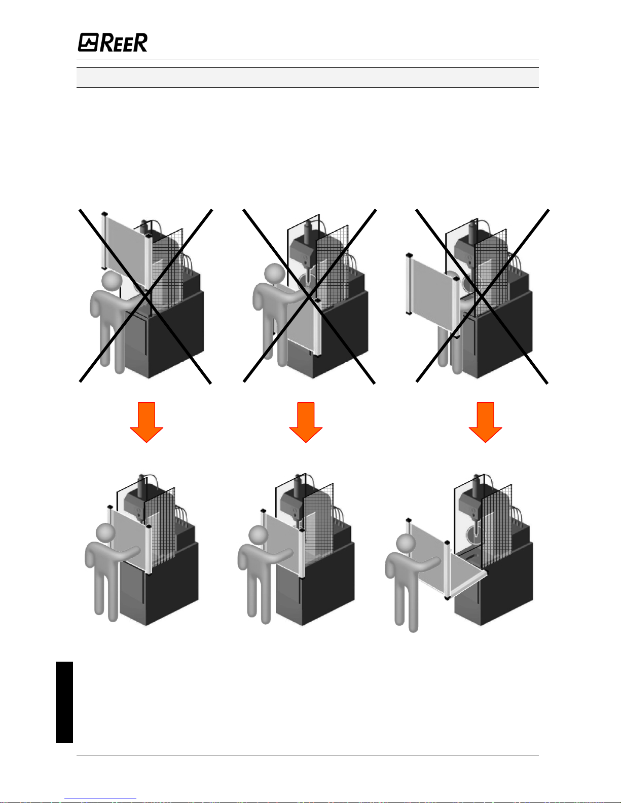
Positioning
The Emitter EOS2E and the Receiver EOS2R must be positioned so that it is
impossible to access the dangerous area from above, from below and from the
sides without intercepting one of the beams. Useful indications for correct
positioning of the light curtain are provided in the figure below.
Incorrect positioning of the light curtain
Correct positioning of the light curtain
Figure 2 - Positioning
English
6 8540738 • 2nd December 2009 • Rev.2
Page 8

EOS2 SAFETY LIGHT CURTAIN
Master/Slave Positioning
In addition to standard models (that can be positioned either horizontally or vertically),
EOS2 can be purchased in a MASTER/SLAVE configuration. This configuration comprises
two (or three) pairs of light curtains in which the two (or three) Emitters and the two (or
three) Receivers are connected in series.
SLAVE
SLAVE
SLAVE2
MASTER
MASTER
Figure 3 – Examples of Master/Slave configurations
The connection cable between the master and slave may be up to 50 metres in length.
This characteristic permits configuration of an application with two light curtains
positioned one at the front and one at the rear of the dangerous machine, with a single
connection towards the machine power and control circuits (Figure 4).
English
Figure 4 - Example of Master/Slave application with mechanical guards
8540738 • 2nd December 2009 • Rev.2 7
Page 9
EOS2 SAFETY LIGHT CURTAIN
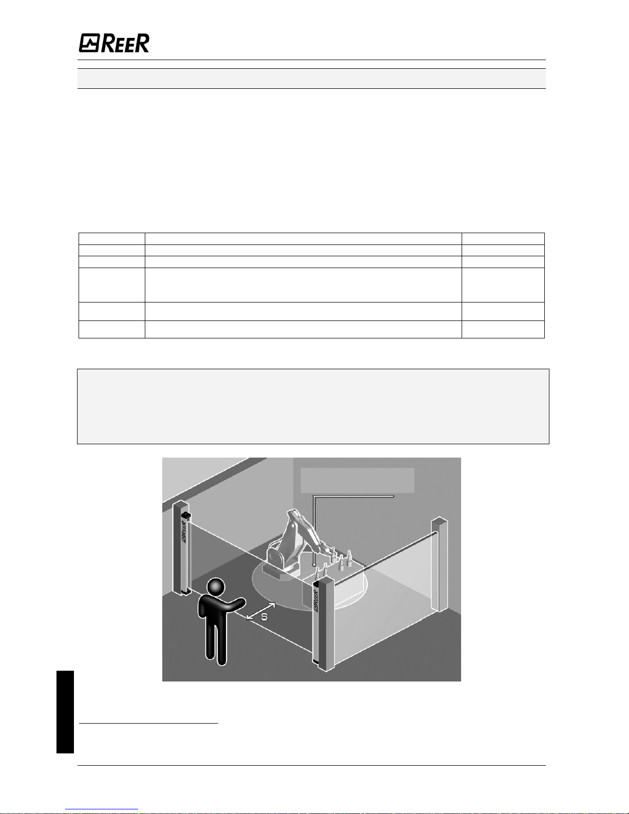
Calculation of safety distance
The light curtain must be positioned at a distance equal to or greater than the minimum
safety distance S so that the dangerous point can be reached only after stopping the
dangerous movement of the machine (Figure 5).
According to the EN999:2008 European standards, the minimum safety distance S must
be calculated using the following formula :
S = K (t1 + t2) + C
C = 8 (d-14)
where:
S Minimum safety distance mm
K Operator approach speed to the dangerous area mm/sec
t1 Total response time of the light curtain, in seconds sec
t2
Response time of the machine in seconds, i.e. the time taken by
the machine to stop the dangerous movement from the moment
in which the stop signal is transmitted
sec
C
Additional distance that varies according to the application
1
mm
d Resolution mm
Table 2 – Safety distance
Failure to comply with the safety distance reduces or impairs the protection function
of the light curtain.
If positioning of the light curtain does not prevent the operator from accessing the
dangerous zone without being detected, additional mechanical guards must be
installed.
DANGEROUS ZONE
Figure 5 – Safety distance S
English
1
For further information on additional safety distance, refer to EN999:2008.
8 8540738 • 2nd December 2009 • Rev.2
Page 10
EOS2 SAFETY LIGHT CURTAIN
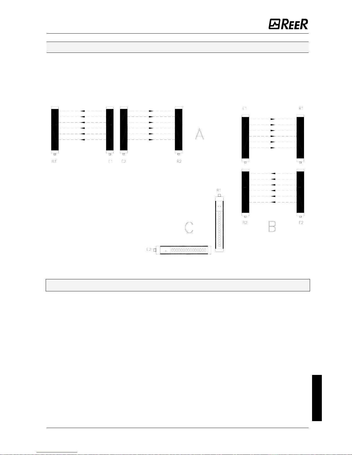
Multiple systems
When several EOS2 are used, precautions must be taken to prevent optical interference
between these: position the elements so that the beam of the Emitter of one system is
received only by its respective Receiver.
Figure 6 provides examples of correct positioning of two photo-electric systems. Incorrect
positioning may cause interference, with possible malfunction of the system.
Systems installed side by side: A
Adjacent positioning of the two emitters
Systems installed one above the other: B
“L” installation: C
Crossed positioning between emitters and
receivers
Figure 6 – Multiple systems
Î
This precaution is not necessary in the case of MASTER/SLAVE systems.
English
8540738 • 2nd December 2009 • Rev.2 9
Page 11

EOS2 SAFETY LIGHT CURTAIN
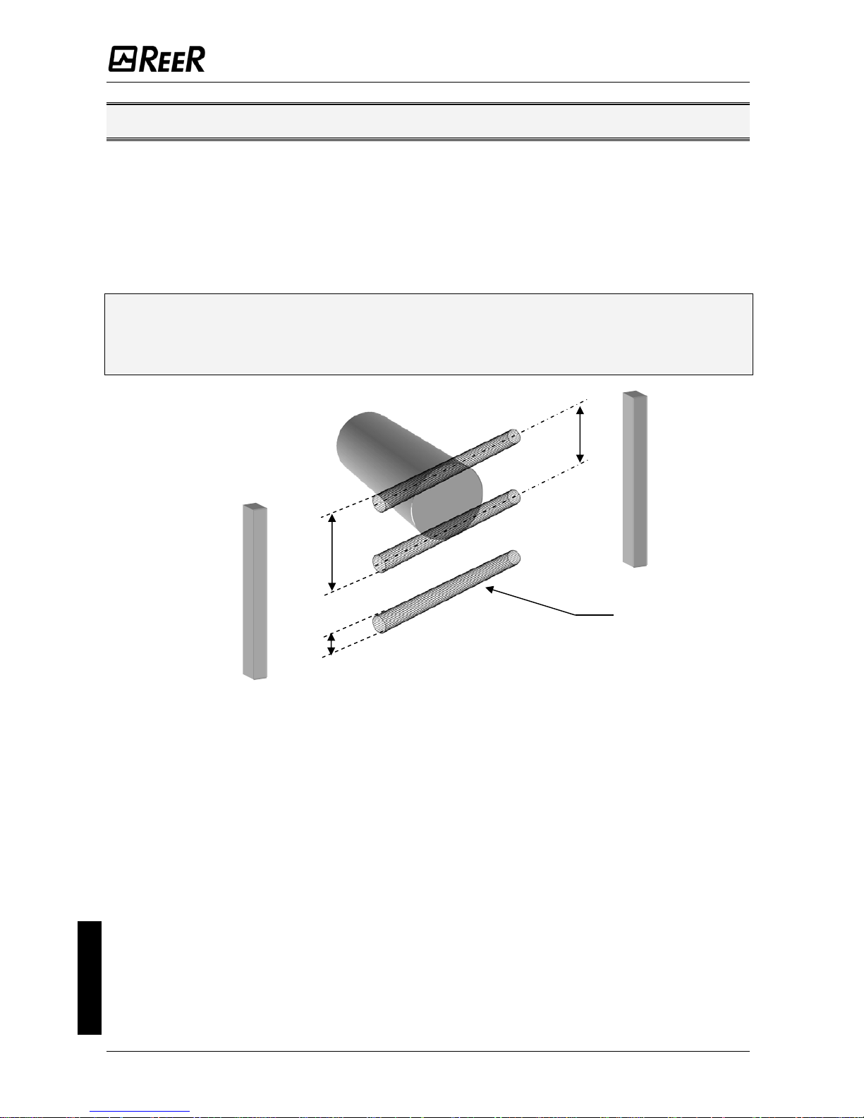
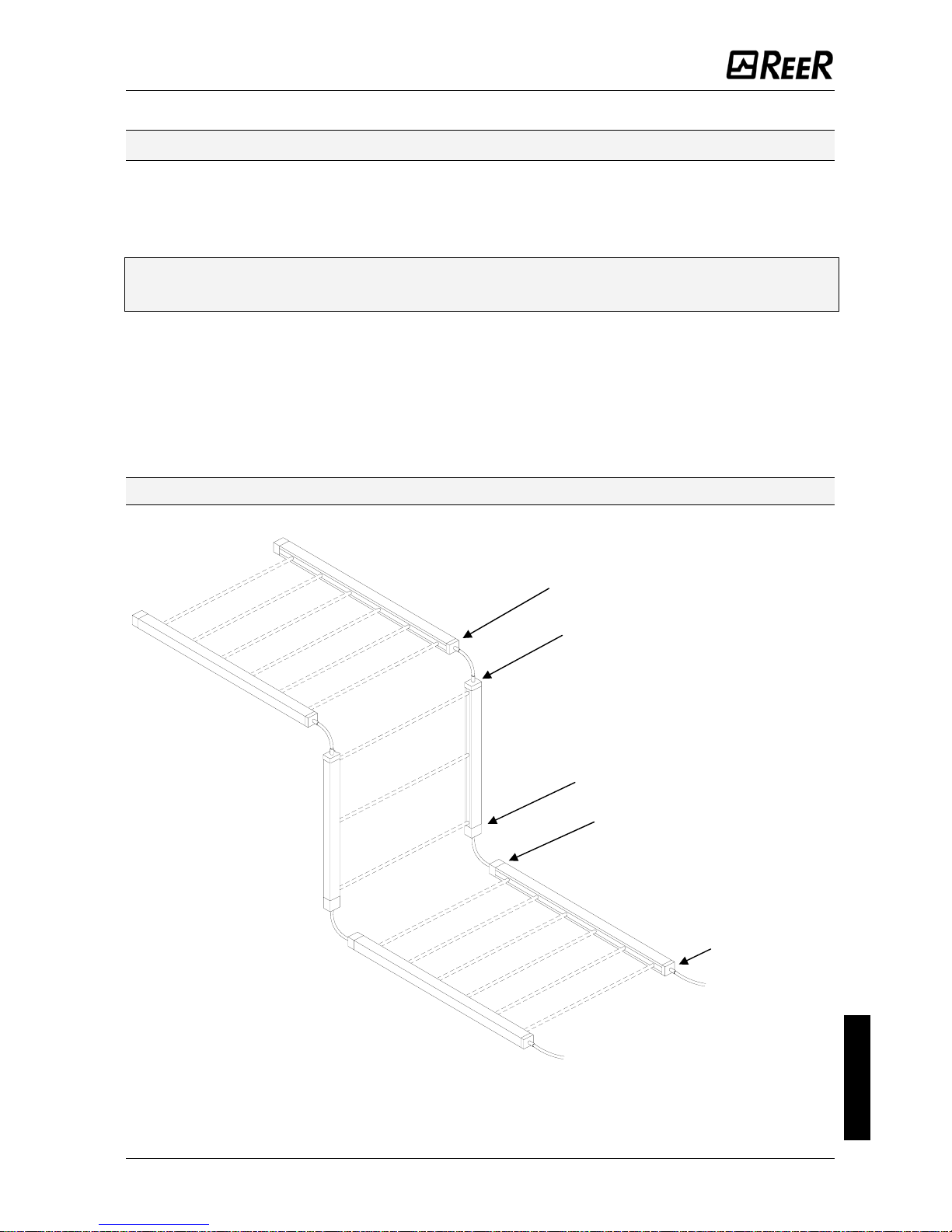
Use of deflecting mirrors
For protection or control of areas accessible from several sides, one or more deflecting
mirrors can be used in addition to the Emitter and Receiver.
Deflecting mirrors make it possible to redirect the beams generated by the Emitter on
several sides.
Wishing to deflect the beams generated by the Emitter by 90°, the perpendicular to the
surface of the mirrors must form an angle of 45° with the direction of the beams.
An application in which two deflecting mirrors have been used for "U" shaped protection
is illustrated in the figure below.
Figure 7 – Deflecting mirrors
When using deflecting mirrors, comply with the following rules:
• Position the mirrors so as to comply with the minimum safety distance S
(
Figure 7) on each side of access to the dangerous area.
• The working distance (working range) is given by the sum of the lengths of all the
access sides to the protected area. (Note that the maximum working range
between the Emitter and Receiver is reduced by 15% for each mirror used).
• In the installation phase, take care to avoid twisting along the longitudinal axis of
the mirror.
• Standing close to and in axis the Receiver, check that the entire shape of the
Emitter is visible on the first mirror.
• It is advisable not to use more than three deflecting mirrors.
English
10 8540738 • 2nd December 2009 • Rev.2
Page 12

EOS2 SAFETY LIGHT CURTAIN
Distance from reflective surfaces
The presence of reflective surfaces close to the light curtain may cause occasional
reflections that prevent sensing. Referring to Figure 8, object A is not detected due to
surface S that, reflecting the beam, closes the optical path between the Emitter and
Receiver. Therefore, a minimum distance d must be maintained between any
reflecting surfaces and the guarded area. The minimum distance d must be
calculated according to the distance l between the Emitter and Receiver and taking
into account that the angle of projection and reception is 5°.
Figure 8 - Reflective surfaces
The distance d to be kept as the distance l between Emitter and Receiver varies is shown
in Picture 9.
d
l
Figure 9 - Minimum distance d
English
After installing the system, check for any reflective surface that intercept the beams, first
of all at the centre and then close to the Emitter and Receiver. During this procedure, the
red led on the Receiver must never switch off.
8540738 • 2nd December 2009 • Rev.2 11
Page 13

EOS2 SAFETY LIGHT CURTAIN
Mechanical assembly and optical alignment
The Emitter and Receiver must be installed facing each other, at a distance equal to or
less than that indicated in the technical data. Using the provided inserts and fastening
brackets, place the Emitter and Receiver so that they are aligned and parallel to each
other, and with the connectors facing the same side.
According to the dimensions and shape of the support to be used to install the Emitter
and Receiver, these must be mounted with the fastening inserts to the rear or inserting
these in the side spline (
Figure 10).
Perfect alignment of the Emitter and Receiver is essential for efficient functioning of the
light curtain; this operation is facilitated observing the indicator leds of the Emitter and of
Receiver.
Figure 10 – Mechanical assembly
Figure 11 – Optical alignment
• Position the optical axis of the first and last beam of the Emitter on the same axis
as that of the corresponding beams on the Receiver.
• Move the Emitter in order to locate the area within which the green led on the
Receiver remains on, then position the first beam of the Emitter (that close to the
indicator led) at the centre of this area.
• Using this beam as pivot, with minor movements of the opposite end, establish the
free protected area condition which, in this situation, will be indicated by lighting
up of the green led on the Receiver.
• Lock the Emitter and the Receiver in place.
Î
If the Emitter and Receiver are installed in areas subject to strong vibrations, vibrationdamping supports must be used (for the order code, see the ACCESSORIES/SPARES
paragraph) so as not to impair operation of the circuits.
English
12 8540738 • 2nd December 2009 • Rev.2
Page 14

EOS2 SAFETY LIGHT CURTAIN
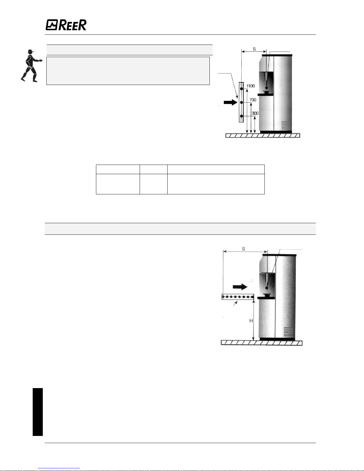
Vertical positioning of the light curtain
Models with 30, 40mm resolution
English
These models are suitable for hand detection.
The minimum safety distance S is calculated according
to the following formula:
S = 2000 (t
1
+ t2) + 8(D-14)
(D=resolution)
This formula is valid for distances S
between 100 and
500 mm. If, according to the calculation, S exceeds
500 mm, the distance can be reduced down to a
minimum of 500 mm using the following formula:
S = 1600 (t
1
+ t2) + 8(D-14)
If, in view of the particular configuration of the
machine, the dangerous zone can be reached from
above, the highest beam of the light curtain must be at
a height H (from resting surface G) whose value is
determined by using the ISO 13855 Standard.
G
Figure 12 -
Vertical positioning
30mm, 40mm
point of
dan
Light curtain
ger
direction
of
approach
reference plane
Models with 50, 90mm resolution
These models are suitable for detecting the arm
or the leg and must not be used to detect
fingers or hands.
The minimum safety distance S is determined
according to the following formula:
S = 1600 (t
1
+ t2) + 850
Î
In every case the height H of the highest beam
from resting surface G must not be smaller
than 900 mm, while the height of the lowest
beam P must not be bigger than 300 mm (ISO
13855 Standard).
G
point of
dan
ger
Light curtain
direction
of
approach
reference plane
Figure 13 - 50mm, 90mm
8540738 • 2nd December 2009 • Rev.2 13
Page 15
EOS2 SAFETY LIGHT CURTAIN
English
Multibeam Models
These models are suitable for whole body
detection and must not be used to detect arms
or legs.
The minimum safety distance S is determined
according to the following formula:
S = 1600 (t
1
+ t2) + 850
The recommend height H from the reference surface G
(ground) is as follows (ISO 13855 Standard) :
G
point of
dan
ger
Light grid
direction
of
approach
Figure 14 - Multibeam
reference plane
MODEL BEAMS Recommended height H (mm)
EOS2 2B
EOS2 3B
EOS2 4B
2
3
4
400 – 900
300 – 700 – 1100
300 – 600 – 900 - 1200
Table 3 - Height H of Multibeam models
Horizontal positioning of the light curtain
When the direction of approach of the body is parallel to
the plane of the protected area, the light curtain must be
positioned so that the distance between the far end of the
dangerous area and the outermost beam is equal to or
greater than the minimum safety distance S calculated as
follows:
S = 1600(t
1
+ t2) + 1200 – 0.4H
where H is the height of the protected surface from
the machine reference plane;
H = 15(D-50)
(D=resolution)
In this case, H must always be less than of 1m
(ISO 13855 Standard).
G
Light curtain
point of
dan
ger
direction
of approach
reference plane
Figure 15 - Horizontal positioning
14 8540738 • 2nd December 2009 • Rev.2
Page 16
EOS2 SAFETY LIGHT CURTAIN
Electrical connections
WARNINGS
Before making electrical connections, make sure that the mains voltage matches the one
indicated in the technical data.
The Emitter and Receiver must be powered at a 24Vdc±20% (PELV, in compliance with
the standard EN 60204-1 (Chapter 6.4)).
The electrical connections must be made according to the wiring diagrams provided in
this manual.
In particular, do not connect other devices to the connectors of the Emitter and Receiver.
To guarantee reliable operation using a diode bridge power supply unit, its output
capacity must be at least 2000μF for each A absorbed.
Layout of the connectors on MASTER/SLAVE light curtain
SLAVE primary connector
SLAVE2 secondary connector
SLAVE
SLAVE 2
SLAVE2 primary connector
MASTER secondary connector
MASTER
MASTER primary
connector
English
Figure 16 - Connector layout
8540738 • 2nd December 2009 • Rev.2 15
Page 17
EOS2 SAFETY LIGHT CURTAIN
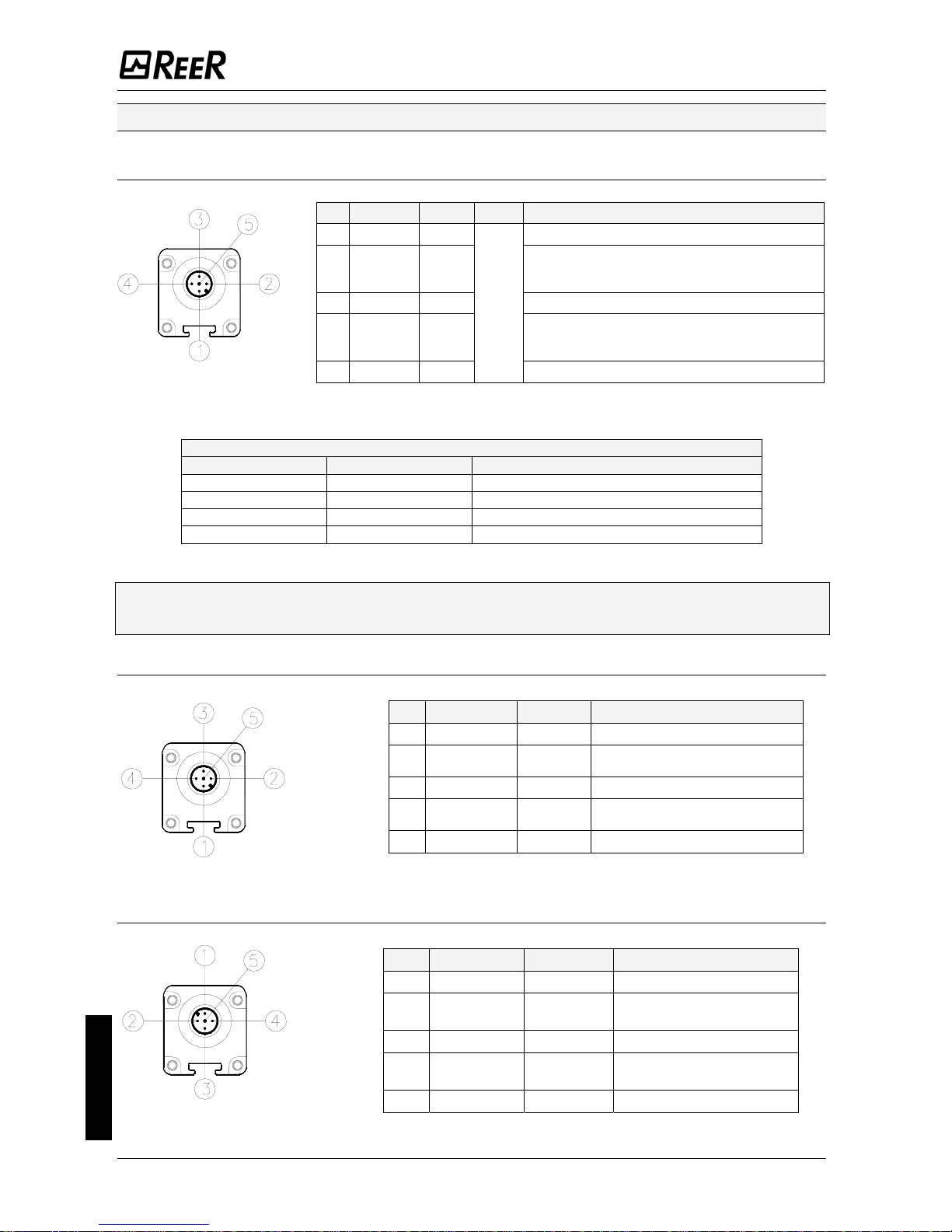
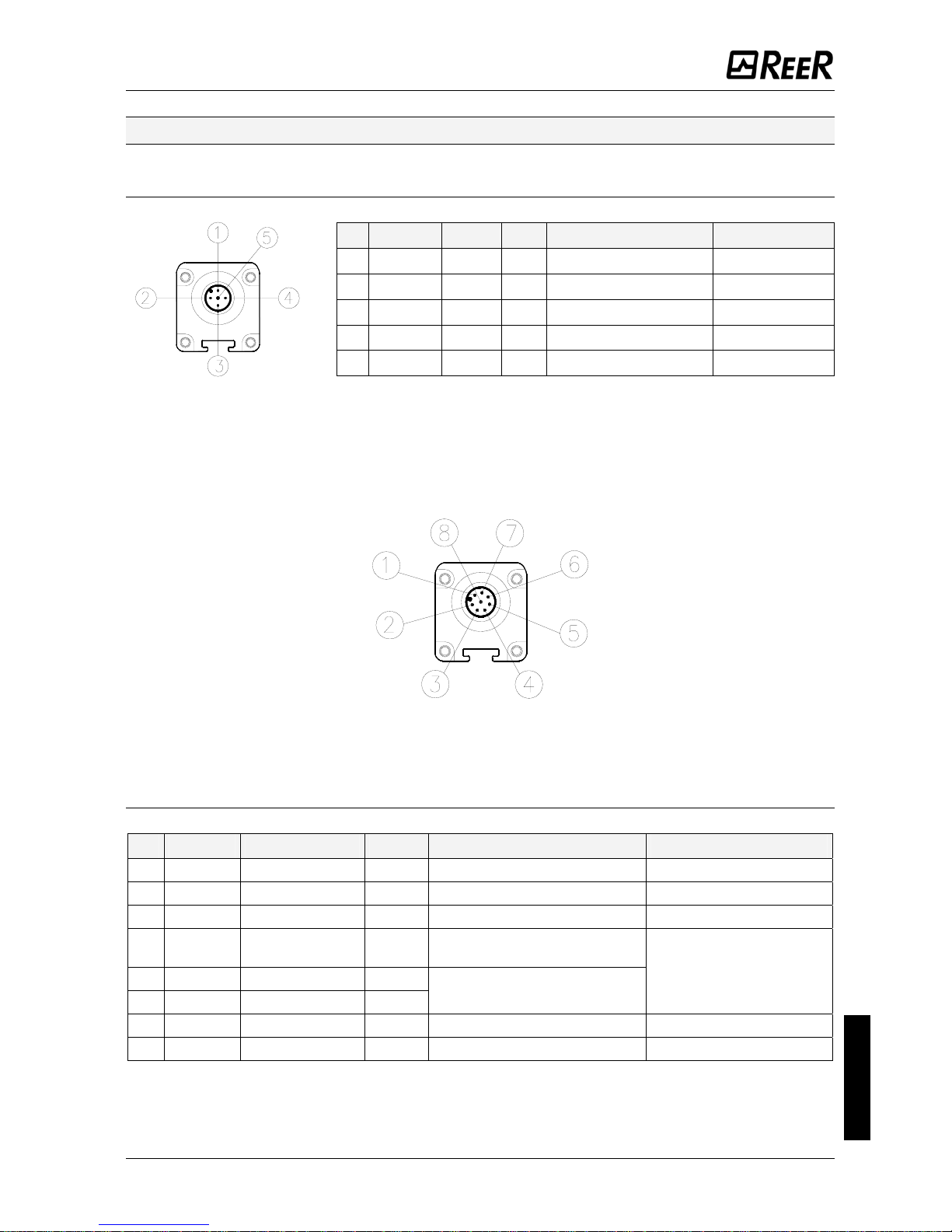
Emitter connections
STANDARD - WITH INTEGRATED CONTROL FUNCTIONS - MASTER MODELS
M12 5-pin primary connectors.
PIN
COLOUR NAME TYPE
DESCRIPTION
1 Brown 24VDC power supply 24VDC
Light curtain configuration
complying with the EN61131-2 standard
(ref.
2 White RANGE0
Table 5)
English
3 Blue 0VDC 0VDC power supply
INPUT
Light curtain configuration
4 Black
complying with the EN61131-2 standard
(ref.
RANGE1
Table 5)
5 Grey Ground connection FE
Table 4 - M12, 5 pin
Master/Standard/with integrated control functions TX
RANGE AND TEST SELECTION - (PRIMARY CONNECTOR M12, 5 PIN)
PIN 4 PIN 2 MEANING
24V 0V
Selection HIGH Range
0V 24V
Selection LOW Range
0V 0V
Emitter in TEST
24V 24V Selection error
Table 5 – Range and TEST selection
Î
For correct operation of the light curtain, pins 2 and 4 of the Emitter must be
connected as indicated in .Table 5
SLAVE/SLAVE2 MODELS - M12, 5-pin primary connector.
PIN COLOUR NAME DESCRIPTION
24VDC power supply
1 Brown 24VDC
Communication
MASTER-SLAVE
2 White
LINE_A
0VDC power supply
3 Blue 0VDC
Communication
MASTER-SLAVE
4 Black
LINE_B
Ground connection
5 Grey FE
Table 6 - M12, 5-pin Primary Slave TX
MASTER MODELS – M12, 5-pin secondary connector.
SLAVE2 MODELS – M12, 5-pin secondary connector.
PIN COLOUR NAME DESCRIPTION
1 Brown 24VDC power supply 24VDC
Communication
MASTER-SLAVE
2 White
LINE_A
3 Blue 0VDC power supply 0VDC
Communication
MASTER-SLAVE
4 Black
LINE_B
5 Grey Ground connection FE
Table 7 - M12, 5-pin Secondary TX
16 8540738 • 2nd December 2009 • Rev.2
Page 18
EOS2 SAFETY LIGHT CURTAIN
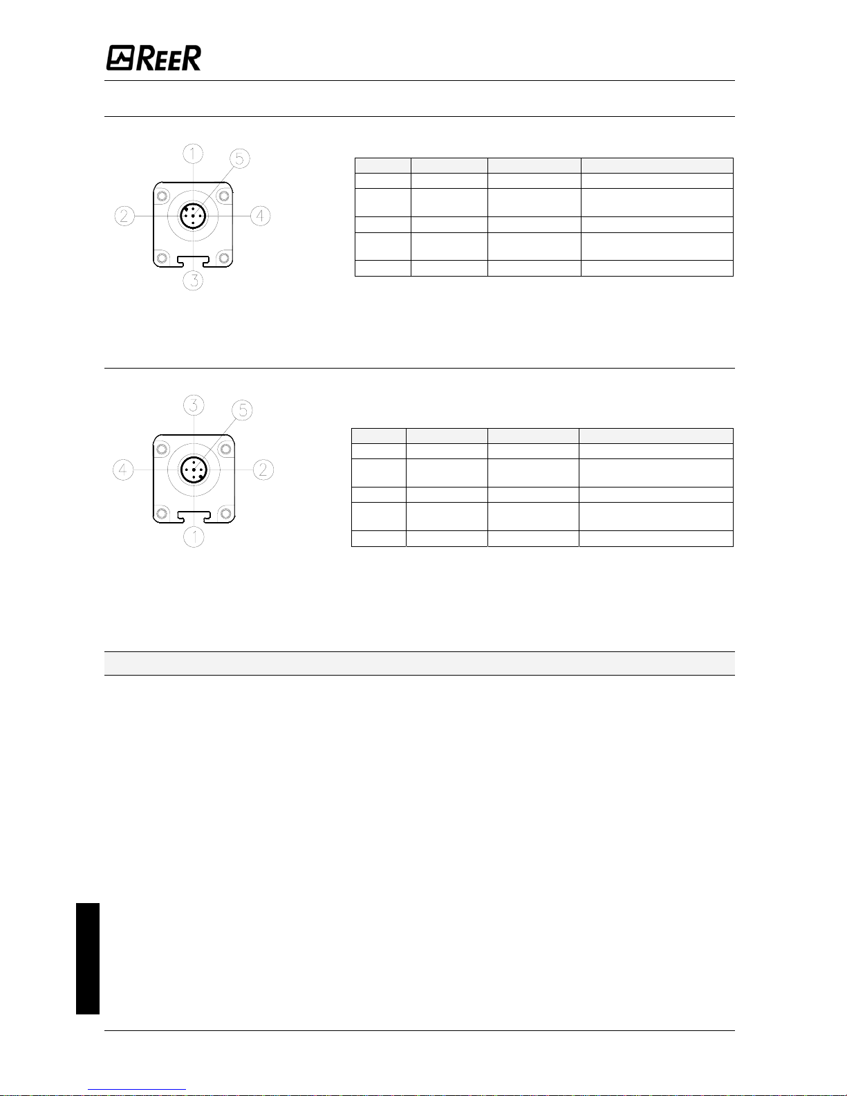
Receiver connections
STANDARD MODELS - M12, 5-pin connector.
PIN COLOUR NAME TYPE
DESCRIPTION OPERATION
1 Brown - 24VDC power supply - 24VDC
2 White OUT Static safety output 1 PNP active high OSSD1
3 Blue - 0VDC power supply - 0VDC
4 Black OUT Static safety output 2 PNP active high OSSD2
5 Grey - Ground connection - FE
Table 8 - M12, 5 pins Primary RX
MODELS WITH INTEGRATED CONTROL FUNCTIONS - M12, 8-pin connector.
MASTER MODELS - M12, 8-pin primary connector.
PIN COLOUR NAME TYPE DESCRIPTION OPERATION
1 White OUTPUT
Static safety output 1 PNP active high OSSD1
2 Brown - 24VDC power supply - 24VDC
3 Green OUTPUT
Static safety output 2 PNP active high OSSD2
Feedback from external
contactors
English
4 Yellow K1_K2/RESTART INPUT
5 Grey SEL_A INPUT
Complying with the
EN61131-2 standard
(ref. Par. "Configuration
and operating modes")
Light curtain configuration
6 Pink INPUT SEL_B
7 Blue - 0VDC power supply - 0VDC
8 Red - Ground connection - FE
Table 9 - M12, 8 pins RX
8540738 • 2nd December 2009 • Rev.2 17
Page 19
EOS2 SAFETY LIGHT CURTAIN
SLAVE/SLAVE2 MODELS - M12, 5-pin primary connectors.
PIN COLOUR NAME DESCRIPTION
1 Brown 24VDC power supply 24VDC
Communication
MASTER-SLAVE
2 White LINE_A
3 Blue 0VDC power supply 0VDC
Communication
MASTER-SLAVE
4 Black LINE_B
5 Grey Ground connection FE
Table 10 - M12, 5 pins Primary Slave RX
MASTER MODELS - M12, 5-pin Secondary Connector.
SLAVE2 MODELS - M12, 5-pin Secondary Connector.
PIN COLOUR NAME DESCRIPTION
1 Brown 24VDC power supply 24VDC
Communication
MASTER-SLAVE
2 White LINE_A
3 Blue 0VDC power supply 0VDC
Communication
MASTER-SLAVE
4 Black LINE_B
5 Grey Ground connection FE
Table 11 - M12, 5 pin Secondary RX
Warnings regarding connection cables
• For connections with a length of more than 50m, use cables having a cross-section
of at least 1mm
2
.
• It is good practice to keep the power supply of the light curtain separate from that
of other electric power equipment (electric motors, inverters, frequency variators)
or other sources of disturbance.
• Connect the Emitter and Receiver to the ground outlet.
• The connection cables must follow a different route from that of other power
cables.
English
18 8540738 • 2nd December 2009 • Rev.2
Page 20
EOS2 SAFETY LIGHT CURTAIN
Configuration and operating modes
(Master Models / With integrated control functions)
The operating mode of the EOS2 light curtain is set by making suitable connections on
the M12 – 8-pin connector of the Receiver (
Table 12).
CONNECTIONS OPERATING MODE
SEL_A (PIN 5)
connected to :
SEL_B (PIN 6)
connected to :
K1_K2/restart (PIN 4)
connected to : 24VDC
AUTOMATIC
(Figure 17)
24VDC 0VDC
K1_K2/restart (PIN 4)
connected to : 24VDC
(via set of NC contacts of K1K2)
SEL_A (PIN 5)
connected to :
SEL_B (PIN 6)
connected to :
AUTOMATIC
with control K1K2
(24VDC 0VDC Figure 18)
K1_K2/restart (PIN 4)
connected to : 24VDC (via RESTART
button)
SEL_A (PIN 5)
connected to :
SEL_B (PIN 6)
connected to :
MANUAL
(
Figure 19)
0VDC 24VDC
K1_K2/restart (PIN 4)
connected to : 24VDC
(via RESTART button and set of NC
contacts of K1K2)
SEL_A (PIN 5)
connected to :
SEL_B (PIN 6)
connected to :
MANUAL
with control K1K2
(
0VDC 24VDC
Figure 20)
Table 12 –Setting of manual/automatic mode
Automatic operation
If the EOS2 light curtain is used in AUTOMATIC mode, it will not be equipped with a
start/restart interlock circuit. In most applications, this safety function is compulsory.
Carefully assess the risks analysis of your own application.
In this operating mode, the OSSD1 and OSSD2 safety outputs follow the status of the light
curtain :
• with guarded area free, the outputs are ON.
• with guarded area occupied, they are OFF.
Manual operation
Use in manual mode (start/restart interlock ON) is compulsory if the safety device
controls an opening in order to protect a dangerous area and if a person, after
passing through the opening, can remain in the dangerous area without being
detected (use as 'trip device' according to IEC 61496). Failure to comply with this
regulation may result in very serious hazards for the persons exposed.
In this operating mode, the safety outputs OSSD1 and OSSD2 are activated in a condition
of free protected area and after having received the RESTART signal via push-button or a
specific command on the K1K2/RESTART input).
Following occupation of the protected area, the outputs will be disabled. For re-activation,
repeat the sequence described above.
The RESTART command is active with a voltage of 24 Vdc.
English
The minimum duration of the command is 100 ms.
8540738 • 2nd December 2009 • Rev.2 19
Page 21

EOS2 SAFETY LIGHT CURTAIN
The Restart command must be installed outside the danger area in a position where
the danger area and the entire work area concerned are clearly visible.
It must not be possible to reach the control from inside the danger area.
Connection of external contactors K1 and K2
In both operating modes, it is possible to activate control of the external contactors
K1/K2. If this control is to be used, it is necessary to connect pin 4 of the M12 8-pin
connector of the Receiver with the power supply (24VDC) via a set of NC contacts
(feedback) of the external contactors.
In the case of manual operation, the RESTART button in series with the NC contacts
(feedback) of the external contactors K1/K2 (
Figure 20) must also be present.
Figure 17 - Automatic
Figure 18 – Automatic with K1K2 feedback
Figure 19 - Manual
English
Figure 20 – Manual with K1K2 feedback
20 8540738 • 2nd December 2009 • Rev.2
Page 22

EOS2 SAFETY LIGHT CURTAIN
Examples of connection with REER safety modules
For correct operation
of the light curtain,
connect pins 2 and 4
of the Emitter as
indicated in Table 4.
Figure 21 - EOS2 A: Manual operation with AD SR1 module
For correct operation
of the light curtain,
connect pins 2 and 4
of the Emitter as
indicated in Table 4.
English
Figure 22 - EOS2 X: Automatic operation with AD SR0 module
8540738 • 2nd December 2009 • Rev.2 21
Page 23
EOS2 SAFETY LIGHT CURTAIN
OPERATION AND TECHNICAL DATA
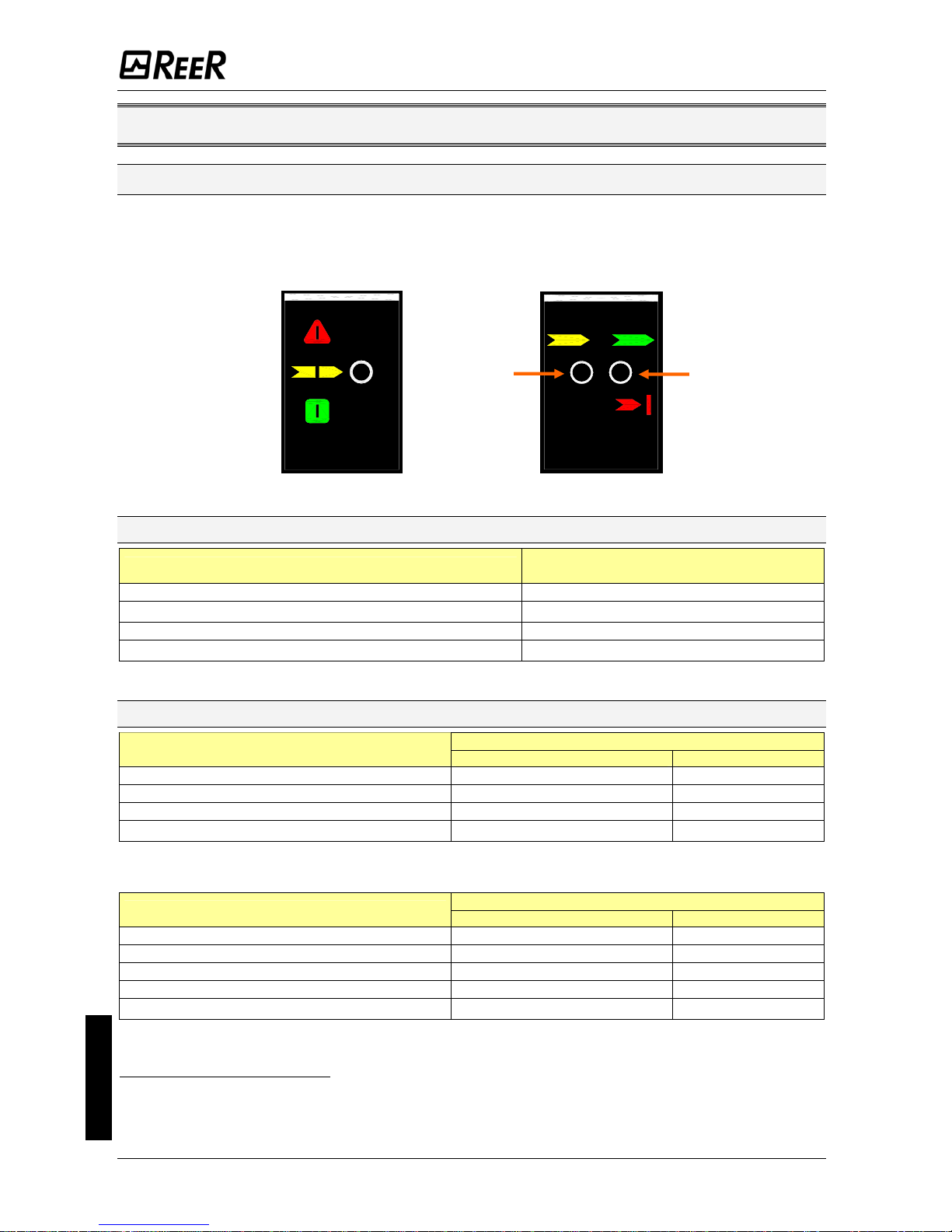
Light signals
The leds on the Emitter and Receiver light up according to system operating conditions.
Refer to the tables below to identify the various indications (ref.
Figure 23).
EMITTER RECEIVER
2
1
Figure 23 - Light signals
Emitter light signals
THREE-COLOUR LED
MEANING
(Red/Green/Orange)
System power-on. Initial TEST. RED
FAIL condition (Table 18)
2
RED BLINKING
TEST condition ORANGE
Normal operating condition
3
GREEN
Table 13 – TX light signals
Receiver light signals
LED
MEANING
TWO-COLOUR (Red/Green) (2) YELLOW (1)
System power-on. Initial TEST. RED ON
BREAK condition (A) RED OFF
GUARD condition (C) GREEN OFF
FAIL condition (Table 18) OFF
RED BLINKING
3
Table 14 – RX light signals EOS2 / EOS2 Slave
LED
MEANING
TWO-COLOUR (Red/Green) (2) YELLOW (1)
System power-on. Initial TEST RED ON
BREAK condition (A) RED OFF
CLEAR condition (B) OFF ON
GUARD condition (C) GREEN OFF
FAIL condition (Table 18) OFF
RED BLINKING
3
Table 15 – RX light signals EOS2 (With integrated control functions)
English
2
The type of fault is identified by the number of flashes (see Troubleshooting chapter)
3
Double blinking (at power-on) of the GREEN led indicates that high range has been selected.
22 8540738 • 2nd December 2009 • Rev.2
Page 24

EOS2 SAFETY LIGHT CURTAIN
LED
MEANING
TWO-COLOUR (Red/Green) YELLOW
System power-on. Initial TEST RED ON
BREAK condition (A) RED OFF
CLEAR condition (B) OFF ON
GUARD condition (C) GREEN OFF
FAIL condition (Table 18) OFF
RED BLINKING
3
MASTER : Light curtain free;
RED Flashing
SLAVE : Light curtain(s) occupied
Table 16 – RX light signals EOS2 (Master)
(A) Light curtain occupied - outputs disabled
(B) Light curtain free - outputs disabled - awaiting restart
(C) Light curtain free - outputs enabled
Internal TEST function
As required according to EN 61496-1, type 2 safety light curtains must be able to check
their internal circuits at regular intervals for any dangerous faults.
The EOS2 with its integrated automatic fault detection system checks correct functioning
of the light curtain within a maximum of 0,5s and always after switching from CLEAR to
GUARD status.
Periodical system TEST
Equipment connected downstream of the light curtain can be checked (without
necessarily occupying the protected area) using the TEST command on the emitter.
This command enables the OSSDs to be switched from ON to OFF as long as it is active.
Please see
Table 5 for details on how to activate this command.
The test function simulates the occupation of the protected area so that correct
functioning of the devices downstream of the light curtain can be checked by an external
supervisor (e.g. PLC, control unit, etc.).
Î
REER recommend to operate a TEST before each work shift.
Î
The minimum duration of the TEST command must be at least 4 msec.
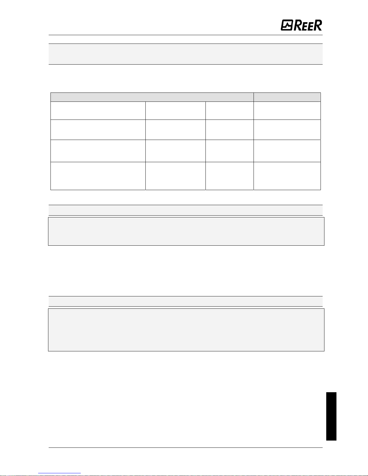
Status of the outputs
On the Receiver of the EOS2 there are two PNP static outputs whose status depends on
the condition of the protected area.
• The maximum permissible load for each output is 400mA@24VDC, corresponding to a resistive load of 60
Ω
.
• The maximum OFF-state voltage is < 0,5VDC.
• The maximum output current in OFF-state (leakage current) is <2mA.
• The maximum load capacity corresponds to 0.82
μ
F@24VDC.
The meaning of the status of the outputs is illustrated in the table below. Any shortcircuit between the outputs or between the outputs and 24VDC or 0VDC power supply is
detected by the light curtain.
SIGNAL NAME CONDITION MEANING
OSSD1
English
24VDC Light curtain free condition.
OSSD2
OSSD1
Light curtain occupied
or fault detected condition
0VDC
OSSD2
Table 17 - Status of the outputs
8540738 • 2nd December 2009 • Rev.2 23
Page 25

EOS2 SAFETY LIGHT CURTAIN
In free protected area conditions, the Receiver provides a voltage of 24VDC on both
outputs. Therefore, the established load must be connected between the output
terminals and the 0VDC (Figure 24).
RECEIVER
RECEIVER
Max. load
400mA
Max. load
400mA
Figure 24 – Correct load connection on the outputs
Technical specifications
TECHNICAL SPECIFICATIONS EOS2 LIGHT CURTAINS
Protected height mm 160 – 1510
Resolutions mm 30 – 40 - 50 - 90
No. of beams (Multibeam Models) 2/3/4 beams
0 ÷ 4 (low)
Working range (selectable) m
3 ÷ 12 (high)
Safety outputs 2 PNP – 400mA @ 24VDC
3 ÷ 19,5 (see models tables)
Response time ms
24 ± 20%
Power supply VDC
Connections M12 (5/8 pin) connectors
Max. length of connections m 100 (50 between Master and Slave)
-10 ÷ 55°C
Operating temperature °C
Protection rating IP 65 - IP 67
Section dimensions mm
2
28 x 30
Max. consumption W 1 (Emitter) 2 (Receiver)
Light curtain lifetime 20 years
IEC 61496-1:2004
IEC 61496-2:2006
Type 2
SIL 2 IEC 61508:1998
English
SILCL 2 IEC 62061:2005
Safety level
PL d - Cat.2 ISO 13849-1
Î
If the EOS2 light curtain is used in a Master-Slave configuration, use the following
formula to calculate the total response time of the device:
t
tot
= [0,1104 * (Nr
slave1
+ Nr
master
) + 1,1044] * 2 (Master + 1 slave)
t
tot
= [0,1104 * (Nr
slave1
+ Nr
slave2
+ Nr
master
) + 1,3228] * 2 (Master +2 slave)
CAPTION
t
tot
= Total response time Nr = number of beams (of the model selected)
24 8540738 • 2nd December 2009 • Rev.2
Page 26

EOS2 SAFETY LIGHT CURTAIN
8540738 • 2nd December 2009 • Rev.2 25
English
30 mm Resolution Models
153 303 453 603 753 903 1053 1203 1353 1503
Number of beams
8 16 23 31 38 46 53 61 68 76
Response time
(EOS models)
ms 4,5 6 8 10 11 13 14,5 16 17,5 19,5
Response time
(Master + 1 slave)
ms
t
tot
= [0,1104 * (Nr
slave1
+ Nr
master
) + 1,1044] * 2
Response time
(Master + 2 slaves)
ms
t
tot
= [0,1104 * (Nr
slave1
+ Nr
slave2
+ Nr
master
) + 1,3228] * 2
Protected height
mm 160 310 460 610 760 910 1060 1210 1360 1510
Curtain tot. height
mm 236,5 386,5
536,5 686,5 836,5 986,5 1136,5 1286,5 1436,5 1586,5
PFHd *
2,04E-08 2,65E-08 3,29E-08 3,90E-08 4,54E-08 5,15E-08 5,78E-08 6,39E-08 7,03E-08 7,64E-08
DCavg
91,3% 91,1% 90,9% 90,7% 90,6% 90,6% 90,5% 90,5% 90,4% 90,4%
MTTFd 100
CCF 80%
40 mm Resolution Models
154 304 454 604 754 904 1054 1204 1354 1504
Number of beams
6 11 16 21 26 31 36 41 46
51
Response time
(EOS models)
ms 4 5 6 7,5 8,5 9,5 10,5 11,5 13 14
Response time
(Master + 1 slave)
ms
t
tot
= [0,1104 * (Nr
slave1
+ Nr
master
) + 1,1044] * 2
Response time
(Master + 2 slaves)
ms
t
tot
= [0,1104 * (Nr
slave1
+ Nr
slave2
+ Nr
master
) + 1,3228] * 2
Protected height
mm 160 310 460 610 760 910 1060 1210 1360 1510
Curtain tot. height
mm 236,5 386,5
536,5 686,5 836,5 986,5 1136,5 1286,5 1436,5 1586,5
PFHd *
1,83E-08 2,29E-08 2,73E-08 3,18E-08 3,63E-08 4,08E-08 4,53E-08 4,98E-08 5,43E-08 5,88E-08
DCavg
#
94,6% 93,8% 93,2% 92,8% 92,4% 92,2% 92,0% 91,8% 91,7% 91,5%
MTTFd
#
years
100
CCF
#
80%
50 mm Resolution Models
155 305 455 605 755 905 1055 1205 1355 1505
Number of beams 4 8 12 16 20 24 28 32 36 40
Response time
(EOS models)
ms 3,5 4,5 5,5 6 7 8 9 10 10,5 11,5
Response time
(Master + 1 slave)
ms
t
tot
= [0,1104 * (Nr
slave1
+ Nr
master
) + 1,1044] * 2
Response time
(Master + 2 slaves)
ms
t
tot
= [0,1104 * (Nr
slave1
+ Nr
slave2
+ Nr
master
) + 1,3228] * 2
Protected height
mm 160 310 460 610 760 910 1060 1210 1360 1510
Curtain tot. height
mm 236,5 386,5
536,5 686,5 836,5 986,5 1136,5 1286,5 1436,5 1586,5
PFHd * 1,75E-08 2,13E-08 2,47E-08 2,85E-08 3,19E-08 3,57E-08 3,91E-08 4,29E-08 4,63E-08 5,01E-08
DCavg
#
94,8% 94,0% 93,5% 93,1% 92,8% 92,5% 92,3% 92,1% 91,9% 91,8%
MTTFd
#
years
100
CCF
#
80%
90 mm Resolution Models 309 459 609 759 909 1059 1209 1359 1509
Number of beams 4 6 8 10 12 14 16 18 20
Response time
(EOS models)
ms
3,5 4 4,5 5 5,5 6 6 6,5 7
Response time
(Master +1 slave)
ms
t
tot
= [0,1104 * (Nr
slave1
+ Nr
master
) + 1,1044] * 2
Response time
(Master + 2 slaves)
ms
t
tot
= [0,1104 * (Nr
slave1
+ Nr
slave2
+ Nr
master
) + 1,3228] * 2
Protected height
mm
310 460 610 760 910 1060 1210 1360 1510
Curtain tot. height mm
386,5 536,5 686,5 836,5 986,5 1136,5 1286,5 1436,5 1586,5
PFHd * 1,82E-08 2,05E-08 2,27E-08 2,50E-08 2,72E-08 2,95E-08 3,18E-08 3,41E-08 3,63E-08
DCavg
#
94,7% 94,2% 93,8% 93,5% 93,2% 93,0% 92,8% 92,6% 92,4%
MTTFd
#
years
100
CCF
#
80%
* IEC 61508
#
ISO 13849-1
Page 27

EOS2 SAFETY LIGHT CURTAIN
Multibeam Models 2B 3B 4B
Number of beams 2 3 4
Distance between the beams mm 500 400 300
Response time ms 3 3,5 3,5
Response time
(Master +1 slave) ms
t
tot
= [0,1104 * (Nr
slave1
+ Nr
master
) + 1,1044] * 2
Response time
(Master + 2 slaves) ms
t
tot
= [0,1104 * (Nr
slave1
+ Nr
slave2
+ Nr
master
) + 1,3228] * 2
Curtain tot. height mm
677,5 977,5 1127,5
1,71E-08 1,87E-08 2,02E-08 PFHd *
DCavg
#
94,9% 94,6% 94,2%
MTTFd
#
years
100
CCF
#
80%
* IEC 61508
#
ISO 13849-1
Dimensions
Figure 25 - Emitter and Receiver
Height
Model
150 300 450 600 750 900 1050 1200 1350 1500
213 363 513 663 813 963 1113 1263 1413 1563 A
236.5 386.5 536.5 686.5 836.5 986.5 1136.5 1286.5 1436.5 1586.5
A (Master/Slave)
61.5 B
29.5 C
11 D
D (Master/Slave2)
(With 2 connectors)
34.5
3 LE TYPE brackets with
3 inserts
2 LE TYPE brackets with 2 inserts Fastening
Model 2B 3B 4B
653 953 1053 A
677 977 1077 A (Master/Slave2)
English
102 B
29.5 C
51 D
75 D (Master/Slave2) (With 2 connectors)
2 LE TYPE brackets with 2 inserts Fastening
26 8540738 • 2nd December 2009 • Rev.2
Page 28

EOS2 SAFETY LIGHT CURTAIN
Figure 26 - FIE inserts and LE fastening brackets (provided)
CHECKOUTS AND MAINTENANCE
Checking of light curtain efficiency
Before each shift or at power-on, check the correct operation of the light curtain.
To do this, comply with the following procedure which uses a test object (available free of
charge on request as accessory) to intercept the beams.
The correct test object must be used for the test, depending on light curtain
resolution. Refer to the Accessories/Spares chapter (page 31) for the correct
ordering code.
Referring to Figure 27:
• Introduce the test object in the protected area and move it slowly up and down,
first at the centre and then close to both the Emitter and Receiver.
• For Multibeam models: using an opaque object, interrupt the beams one by one,
first of all at the centre and then close to the Emitter and Receiver.
• Check that, in each phase of test object movement, the red led on the Receiver
always remains ON.
Figure 27 – Efficiency check
English
The EOS2 light curtain does not require any specific maintenance; however, it is good
practice to clean the front protective surfaces of the mirrors of the Emitter and Receiver.
Clean with a damp cloth; in very dusty environments, after cleaning the front surface,
spray with an anti-stat product.
8540738 • 2nd December 2009 • Rev.2 27
Page 29

EOS2 SAFETY LIGHT CURTAIN
Never use abrasive or corrosive products, solvents or alcohol that could damage the
part to be cleaned or wool cloths in order to prevent electrifying the front surface.
Even very fine scratching of the front plastic surfaces may increase the width of the
beam emitted by the light curtain, thereby impairing its efficiency in the presence of
reflecting side surfaces.
Therefore, during cleaning, it is essential to dedicate particular attention to the front
window of the light curtain, in particular in environments characterised by abrasive
powders (e.g. cement works etc).
English
28 8540738 • 2nd December 2009 • Rev.2
Page 30

EOS2 SAFETY LIGHT CURTAIN
Troubleshooting
The indications provided by the leds on the Emitter and Receiver make it possible to trace
the cause of any system malfunction. As indicated in the “LIGHT SIGNALS” paragraph of
this manual, in the case of a fault, the system switches to stop status and the leds of each
unit indicate the type of fault that has occurred. (See the tables below). The numbers of
the leds are referred to
Figure 23.
EMITTER
THREE-COLOUR LED
REMEDY
MEANING
(Red/Green/Orange)
Irregular connection of
pins 2 and 4
- Check connections of pins 2 & 4.
RED 2 consecutive flashes
- Send to REER for repair.
Internal failure
RED 3/4 consecutive flashes
Master and slave not
compatible
- Check model compatibility
RED 5 consecutive flashes
- Check condition of the Master.
English
Awaiting communication
Master/Slave
4
ORANGE Flashing
- If in FAIL condition, check the type of
fault.
- If the fault persists, send the device to
ReeR laboratories for repair.
Loss of Master/Slave
communication
5
ORANGE 2 consecutive flashes
onnections.
-
Slave to ReeR laboratories for repair
- Check Master/Slave c
- Reset of the system.
If the fault persists, send Master and
RECEIVER
MEANING TWO-COLOUR (Red/Green) REMEDY
- Check connections.
Incorrect configuration
RED 2 consecutive flashes
No feedback from
- Check connection of pin 4.
external contactors
RED 3 consecutive flashes
Carefully locate the interfering Emitter and
s:
hat it
- ams emitted by the
sing opaque
take action in one of the following way
- Reduce the range of the interfering
Emitter from High to Low
- Swap over the position of Emitter and
Receiver
Interfering emitter
detected
RED 4 consecutive flashes
- Move the interfering Emitter so t
does not illuminate the Receiver
Shield the be
interfering Emitter u
protections
- nnections. Check co
- If the fault persists, send to REER for
repair.
OSSD outputs error
5 c esRED onsecutive flash
- Send the device to ReeR laboratories for
repair
6/7 consecutive
flashes
Internal failure
RED
- Check Master/Slave connections
- If the fault persists, send the device to
ReeR laboratories for repair.
Incorrect Master/Slave
connections
6
RED 8 consecutive flashes
Table 18 - Troubleshooting
4
Indication present only on Slave light curtains
5
Indication present only on Master and Slave light curtains
6
Indication present only on Master and Slave2 light curtain
8540738 • 2nd December 2009 • Rev.2 29
Page 31

EOS2 SAFETY LIGHT CURTAIN
In any case, if a system stoppage occurs, switch the system off and on again to check
whether the incorrect behaviour of the system is to be ascribed to transitory
electromagnetic disturbances.
If the malfunction persists:
• Check that electrical connections are correct and undamaged;
• Check that supply voltage levels comply with those indicated in the technical data.
• Check that the Emitter and the Receiver are correctly aligned and that front
surfaces are perfectly clean.
• It is advisable to keep the power supply of the light curtain separate from that of
other electric power equipments (electric motors, inverters, frequency variators) or
other sources of disturbance.
If it is not possible to trace the cause of the malfunction and eliminate this, stop the
machine and contact the Reer assistance service.
If the checks suggested are not sufficient to restore the correct operation of the system,
please send the device, with all its parts, to the REER laboratories, clearly indicating:
• product code number (P/N field shown in the product label);
• serial number (S/N field shown in the product label);
• date of purchase;
• period of operation;
• type of application;
• detected fault.
English
30 8540738 • 2nd December 2009 • Rev.2
Page 32

EOS2 SAFETY LIGHT CURTAIN
Accessories/Spares
MODEL ITEM CODE
ADMIRAL AD SR1 safety module 1330900 AD SR1
ADMIRAL AD SRM safety module with muting function 1330904 AD SRM
ADMIRAL AD SR0 safety relay 1330902 AD SR0
ADMIRAL AD SR0A safety relay 1330903 AD SR0A
Straight M12 5-pin female connector with 5-m cable 1330950 CD5
90° M12 5-pin female connector with 5-m cable 1330951 CD95
Straight M12 5-pin female connector with 15-m cable 1330952 CD15
90° M12 5-pin female connector with 15-m cable 1330953 CD915
Straight M12 5-pin female connector PG9 1330954 CDM9
90° M12 5-pin female connector PG9 1330955 CDM99
Straight M12 8-pin female connector with 5m cable 1330980 C8D5
Straight M12 8-pin female connector with 10m cable 1330981 C8D10
Straight M12 8-pin female connector with 15m cable 1330982 C8D15
90° M12 8-pin female connector with 5m cable 1330983 C8D95
90° M12 8-pin female connector with 10m cable 1330984 C8D910
90° M12 8-pin female connector with 15m cable 1330985 C8D915
Straight M12 8-pin female connector PG9 1330986 C8DM9
90° M12 8-pin female connector PG9 1330987 C8DM99
0.3m cable with 2 straight M12 5-pin female connectors 1330990 CDS03
3m cable with 2 straight M12 5-pin female connectors 1360960 CJBE3
5m cable with 2 straight M12 5-pin female connectors 1360961 CJBE5
10m cable with 2 straight M12 5-pin female connectors 1360962 CJBE10
Test rod diameter 30mm 1330962 TR30
Test rod diameter 40mm 1330963 TR40
Test rod diameter 50mm 1330964 TR50
Set of 4 fastening accessories (brackets, inserts and bolts)
for models up to 1050
1310970 SA 4
Set of 6 fastening accessories(brackets, inserts and bolts)
for models from 1200
1310971
SA 6
Set of 4 vibration-damping supports (for models h=150) 1310972 SAV4E
Set of 8 vibration-damping supports (for models h=300÷1050) 1310973 SAV8E
Set of 12 vibration-damping supports (for models h=1200÷1500) 1310974 SAV12E
English
8540738 • 2nd December 2009 • Rev.2 31
Page 33

EOS2 SAFETY LIGHT CURTAIN
GUARANTEE
All new EOS2 systems are guaranteed by REER for a period of 12 (twelve) months under
normal working conditions, against defects due to faulty materials and workmanship.
During the aforesaid period, REER promises to replace faulty parts free of charge. This
guarantee covers both material and labour.
REER reserves the right to decide whether to repair equipment or replace it with
equipment of the same type or having the same characteristics.
The validity of this guarantee is subject to the following conditions:
• The user must notify REER of the fault within twelve months following the date of
delivery of the product.
• The equipment and all parts thereof must be in the condition in which they were
supplied by REER.
• The defect or malfunction must not arise directly or indirectly from:
- Improper use
- Non-observance of the instructions for use;
- Negligence, inexperience, improper maintenance;
Repairs, modifications and adjustm
- ents carried out by personnel not
acts of God);
- Other reasons for which REER cannot be held responsible.
ries, to which the material must be
amage or loss of material during
d for costs, suspension
f activities or any other events or circumstances related in any way to malfunctioning of
e product or any parts thereof will be taken into consideration.
authorised by REER, tampering, etc.;
- Accidents or collisions (also during transportation or due to
Repairs will be carried out at REER’s laborato
consigned or forwarded: transport costs and any d
transportation will be charged to the Customer.
All replaced products and parts are property of REER.
REER does not recognise any other form of guarantee or rights other than those expressly
stated above; no requests for compensation for damages incurre
o
th
Precise, complete compliance with all the indications and warnings indicated in this
manual is essential for correct operation of the light curtain. Therefore, REER s.p.a.
English
declines any responsibility for defects caused by even partial non-compliance with
such indications.
Characteristics liable to modifications without prior notice. • Complete or partial reproduction is forbidden with out REER’ s prior authorisat ion.
32 8540738 • 2nd December 2009 • Rev.2
 Loading...