

Operating Instructions
Quadrocopter „Shadow 2.0“ RTF
Item no. 1400004
Version 10/16

Table of Contents
Page
1. Introduction .......................................................................................................................................................... 4
2. Explanation of Symbols ....................................................................................................................................... 4
3. Intended Use .......................................................................................................................................................5
4. Scope of Delivery ................................................................................................................................................. 5
5. Product Description .............................................................................................................................................6
6. Safety Information ................................................................................................................................................ 7
a) General Information ....................................................................................................................................... 7
b) Mains Unit ...................................................................................................................................................... 8
c) Before Commissioning .................................................................................................................................. 8
d) During Operation ........................................................................................................................................... 8
7. Notes on Batteries and Rechargeable Batteries ................................................................................................ 10
8. Preparation of the Quadrocopter ....................................................................................................................... 11
a) Assemblies, Displays and Attachments ....................................................................................................... 11
b) Mounting the Propellers ............................................................................................................................... 12
c) Stabilised Camera Holder (2 D-Gimbal) ...................................................................................................... 13
d) Charging the Flight Battery .......................................................................................................................... 14
e) Testing the Rechargeable Battery Charge Condition ..................................................................................15
9. Transmitter Controls ..........................................................................................................................................16
10. Setting up the Transmitter ..................................................................................................................................18
a) Inserting the Batteries .................................................................................................................................. 18
b) Switching on the Transmitter .......................................................................................................................18
c) Setting the Control Stick Length .................................................................................................................. 21
11. Commissioning of the Quadrocopter .................................................................................................................22
a) Checking Activation/Deactivation function of the Flight Battery ...................................................................22
b) Inserting the Flight Battery into the Quadrocopter ....................................................................................... 23
c) Calibration of the Compass ......................................................................................................................... 24
d) Basic Information Relevant for Controlling of Quadrocopters .....................................................................25
e) Setting the Toggle Switches ........................................................................................................................29
f) Starting the Quadrocopter ........................................................................................................................... 30
g) Trimming the Quadrocopter .........................................................................................................................31
h) Overview of the Flashing Displays of the Status LEDs ...............................................................................32
2

Page
12. Overview of the Flight Modes ............................................................................................................................33
a) „Manual Mode“ ............................................................................................................................................33
b) „GPS Mode“ ................................................................................................................................................. 33
c) „IOC“ Function (Smart Flight Orientation) .................................................................................................... 33
d) „CL Mode“ ....................................................................................................................................................34
e) „HL Mode“ ....................................................................................................................................................35
f) „POI Mode“ .................................................................................................................................................. 35
13. Activating the Flight Modes ................................................................................................................................36
14. „Go-Home“ Function ..........................................................................................................................................37
15. „Following“ Function ..........................................................................................................................................39
16. Undervoltage Warning ....................................................................................................................................... 40
17. Failsafe Function ...............................................................................................................................................40
18. Flight Space Limitation and Flight Prohibition Zones .........................................................................................41
19. Gimbal Control ...................................................................................................................................................42
20. Binding Function ................................................................................................................................................43
21. Programming the Remote Control .....................................................................................................................44
22. The System Setting Menu „System Setup“ ........................................................................................................45
a) Control stick Assignment „Sticks mode“ ......................................................................................................45
b) Display Brightness „LCD brightness“ ........................................................................................................... 47
c) Transmitter Software Version „Firmware ver.“ .............................................................................................48
d) Transmitter Software Update „Firmware update“ ........................................................................................49
e) Reset to Factory Settings „Factory reset“ .................................................................................................... 50
23. The Function Setting Menu „Functions setup“ ...................................................................................................51
a) Control Encoder Test „Display“ ....................................................................................................................52
b) Basic Trim „Subtrim“ .................................................................................................................................... 53
24. Maintenance and Care ......................................................................................................................................54
25. Disposal ............................................................................................................................................................. 54
a) General Information ..................................................................................................................................... 54
b) Batteries and Rechargeable Batteries ......................................................................................................... 54
26. Troubleshooting .................................................................................................................................................55
27. Declaration of Conformity (DOC) .......................................................................................................................56
28. Technical Data ...................................................................................................................................................56
3
1. Introduction
Dear Customer,
thank you for purchasing this product.
This product complies with the statutory national and European requirements.
To maintain this status and to ensure safe operation, you as the user must observe these operating instructions!
These operating instructions are part of this product. They contain important notes on commissioning and
handling. Also consider this if you pass on the product to any third party.
Therefore, retain these operating instructions for reference!
All company names and product names are trademarks of their respective owners. All rights reserved.
If there are any technical questions, please contact:
International: www.conrad.com/contact
United Kingdom: www.conrad-electronic.co.uk/contact
2. Explanation of Symbols
The symbol with a lightning bolt in a triangle is used where there is a health hazard, e.g. from electric
shock.
The symbol with the exclamation mark points out particular dangers associated with handling, function or
operation.
The arrow symbol indicates special advice and operating information.
4
3. Intended Use
This product is an electrically powered helicopter-like model with wireless radio control via the remote control system
included in the delivery. The quadrocopter is solely designed for private use in the eld of model construction and the
operating times associated with it.
The model is designed for operation outdoors but may also be used in sufciently sized rooms (e.g. gyms) if required.
The enclosed LiPo ight battery can be charged with an enclosed charter.
This system is not suitable for other types of use. Any use other than that described above can damage the product
and involves additional risks such as short circuit, re, electric shock, etc.
The product must not get damp or wet.
The product is not suitable for children under 14 years of age.
Observe all safety information in these operating instructions. They contain important information on hand-
ling of the product.
You are solely responsible for the safe operation of your remote control and your model!
4. Scope of Delivery
• Quadrocopter with 2D-gimbal, assembled ready to y
• Radio remote control transmitter with GPS aerial
• Flight battery with integrated electronics
• Mains unit with charge adapter
• Mains connection cable
• USB cable
• Exchange blades screwdriver
• Binding plug
• Operating instructions
Latest operating instructions:
1. Open the website www.produktinfo.conrad.com in your browser or scan the QR
2. Select the type of document and the language and then enter the corresponding
code on the right.
order number into the search box. Start searching and download the documents
found.
5

5. Product Description
The ready-to-y quadrocopter has 4 separate motors that drive one propeller each. Concurrent acceleration of all
propellers permits the quadrocopter to lift off of the ground and hover stably in the air at the corresponding propeller
speeds.
The enclosed remote control permits controlling the quadrocopter specically to the desired ight altitude and direction.
The installed GPS receiver enables the quadrocopter to orient itself in the open eld to independently perform complex ight manoeuvres. Another GPS receiver that is connected to the remote control transmitter enables the quadro-
copter to automatically follow the moving transmitter.
To better recognise the alignment of the model in ight, the two arms pointing forward are lit white from below, the ones
pointing back are lit red. The current operating condition of the quadrocopter is displayed with status LEDs.
The enclosed 2.4 GHz radio remote control system may be switched from „Mode 2“ to „Mode 1“ without any great
effort and permits detailed control of the model.
Below the quadrocopter, a camera holder (2D gimbal) that is stabilised around two axes is installed. It may hold action
cams of the GoPro type or corresponding cameras with the same dimensions, and permits a perfectly calm video in
ight.
Legal note:
Observe the legal basics of your country regarding photographs and videos of persons, objects and fa-
cilities, as well as their publication. You alone are taking full responsibility if use of the quadrocopter as a
camera carrier violates any rights, laws or regulations.
Commercial use of the quadrocopter requires a ight permission in Germany.
Also observe applicable provisions under ight law, such as the max. permissible ight altitude or ight
prohibitions for models in direct proximity of airelds or military facilities. Find out in how far these or other
provisions and regulations must be observed and complied with at the planned site of use.
Even though the quadrocopter can y autonomously, you alone are responsible for use of the ight unit.
For operation of the transmitter, 4 AA/mignon batteries (e.g. Conrad item no.: 652506, order 4x) are required.
6

6. Safety Information
In case of damage caused by non-compliance with these operating instructions, the warranty/gua-
rantee will expire. We do not assume any liability for consequential damage!
We do not assume any liability for property damage and personal injury caused by improper use or
non-compliance with the safety instructions! In such cases the warranty/guarantee is voided.
Normal wear and tear during operation (e.g. worn-out motor-shaft bearings) are excluded from the guaran-
tee and warranty, the same is the case for accidental damage (e.g. broken housing parts or propellers).
Dear customer, these safety instructions are not only for the protection of the product but also for your own
safety and that of other people. Therefore, read this chapter very carefully before taking the product into
operation!
a) General Information
Caution, important note!
Operating the model may cause damage to property and/or individuals. Therefore, make sure that you are
sufciently insured when using the model, e.g. by taking out private liability insurance.
If you already have private liability insurance, verify whether or not operation of the model is covered by your
insurance before commissioning your model.
Note: In some countries you are required to have insurance for all model aircraft!
• The unauthorised conversion and/or modication of the product is prohibited for safety and approval reasons.
• This product is not a toy and not suitable for children under 14 years of age.
• The product must not get damp or wet.
• As delicate control electronics are used in the quadrocopter which are also sensitive to temperature uctuations
and are optimised for a particular temperature range, operation below +10 °C is to be avoided. The product was
developed for operation at an ambient temperature between +10 °C and +40 °C and a humidity that is normal for
dry weather in Central Europe. Operation under different conditions can lead to changed (material) properties and
damage to the product as a result.
• If you do not have sufcient knowledge regarding handling of remote-controlled models, contact an experienced
model sportsman or model construction club.
• Do not leave packaging material unattended. It may become a dangerous toy for children.
• Should questions arise that are not answered by these operating instructions, contact us (for contact information,
see chapter 1) or another expert.
The operation and handling of remote controlled quadrocopters must be learned! If you have never steered such a
model, start especially carefully and get used to the reactions of the model to the remote control commands rst. Be
patient!
7

b) Mains Unit
• The mains unit is constructed pursuant to protection class II.
• Use only a proper mains socket of the public mains for voltage/power supply of the mains unit. Use the enclosed
mains cable for connection.
• The socket to which the mains unit‘s connection cable is connected must be easily accessible.
• Do not pull the plug of the mains cable from the mains socket by pulling the cable. Always take the plug and pull it
straight from the mains socket.
• Protect the mains unit/mains cable from moisture and wetness as well as from damage.
If the mains unit/mains cable has gotten moist or wet or damaged, do not touch it. Danger to life from electric
shock!
First deactivate all sides of the mains socket to which the mains unit/mains cable is connected (e.g. switch
off the respective fuse or turn out the fuse. Then deactivate the FI protection switch).
Only then pull the mains plug of the mains cable from the mains socket; no longer use the mains unit/mains
cable, but dispose of it environmentally compatibly.
c) Before Commissioning
• Always rst switch on the transmitter and then connect the ight battery to the quadrocopter. This is the only way for
an attunement function to take place between transmitter and receiver, so that your model will react reliably to the
control commands of your transmitter.
• Check the functional safety of the model and remote control system. Watch out for any visible damage such as
defective plug connections or damaged cables. All moving parts on the model must run smoothly but must not have
any tolerance in the bearing.
• The ight battery required for operation must be charged before operation.
• Ensure that the batteries in the transmitter have a sufcient remaining capacity (transmitter indication). If the batte-
ries are empty, always replace the complete set, never individual cells only.
• Give the quadrocopter enough time to receive the required GPS satellites so that the quadrocopter can perform
autonomous ight manoeuvres. Observe the ashing displays of the status-LEDs.
d) During Operation
• Do not take any risks when operating the product! Your own safety and that of your environment depends completely
on your responsible use of the model.
• Improper operation can cause serious damage to people and property! Therefore make sure to keep a sufciently
safe distance from persons, animals or objects during operation. Never try to grab the ying model with your hand!
• When you operate the model, always make sure that no parts of your body, other people or objects come within the
dangerous range of the propellers.
• Only y your model if your ability to react is unlimited. The inuence of tiredness, alcohol or medication can cause
incorrect responses.
• Motors, motor regulator and ight battery can heat during operation. For this reason, wait for 10 to 15 minutes before
recharging or replacing the ight battery or taking off again with a second, already-charged ight battery.
8

• Never switch off the remote control (transmitter) while the model is in use. After landing, always switch off the ight
battery before the remote control. Then remove the ight battery from the quadrocopter.
• Never switch off the remote control while the quadrocopter is still in operation.
• Never expose your model and the remote control system to direct solar irradiation or great heat for an extended
period.
9

7. Notes on Batteries and Rechargeable Batteries
Although use of batteries and rechargeable batteries in everyday life is a matter of course today, there are
many dangers and problems.
Ensure that you observe the following general information and safety information when handling batteries
and rechargeable batteries.
• Keep batteries/rechargeable batteries out of the reach of children.
• Do not leave any batteries/rechargeable batteries lying around openly. There is a risk of batteries being swallowed
by children or pets. If swallowed, consult a doctor immediately!
• Batteries/rechargeable batteries must never be short-circuited, disassembled or thrown into re. There is a danger
of explosion!
• Leaking or damaged batteries/rechargeable batteries can cause chemical burns to skin on contact; therefore, use
suitable protective gloves.
• Do not recharge normal batteries. There is a risk of re and explosion! Only charge rechargeable batteries (1.2 V)
intended for this purpose. Use suitable battery chargers. Batteries (1.5 V) are intended for one-time use only and
must be disposed of properly when discharged.
• Always observe the correct polarity when inserting batteries or connecting the charger (observe plus/+ and minus/-).
Incorrect polarity will damage not only the transmitter but also the plane model and the batteries. There is a danger
of re and explosion.
• Always replace the whole set of batteries. Do not mix full batteries with half-full ones. Always use batteries/rechar-
geable batteries of the same type and manufacturer.
• Never mix batteries and rechargeable batteries! Therefore, only use batteries for the remote control transmitter.
• If the device is not used for an extended period of time (e.g. storage), remove the inserted batteries from the remote
control to avoid damage from leaking batteries.
Attention!
After ying, switch off the ight battery and remove the ight battery from the quadrocopter. Do not leave
the ight battery in the quadrocopter when you are not using the model (e.g. during transport or storage).
Otherwise, the ight battery may be fully discharged and is thus destroyed/unusable!
• Never charge the ight battery right after use. Always let the ight battery to cool down until it has reached room or
ambient temperature again.
• Only charge intact and undamaged ight batteries. If the outer isolation of the rechargeable battery is damaged or
the battery is deformed or bloated, it must not be charged. There is acute danger of re or explosion!
• Never damage the outer shell of the ight battery, do not cut the foil cover, do not puncture the ight battery with
pointed objects. There is a risk of re and explosion!
• Never recharge the ight rechargeable battery unattended.
• Disconnect the ight battery from the charger when it is charged completely.
10
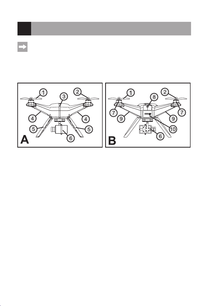
8. Preparation of the Quadrocopter
In the further course of these instructions, gures in the text always refer to the adjacent gure or the gures
within the section. References to other gures are indicated with the corresponding gure number.
a) Assemblies, Displays and Attachments
Illustration A in gure 1 shows the quadrocopter from the front. Illustration B in gure 1 shows the quadrocopter from
the rear.
Figure 1
1 Propeller
2 Propeller nut
3 Status LEDs
4 Propeller arm lighting front
5 Landing frame
6 2D-gimbal
7 Brushless motor
8 USB interface
9 Propeller arm lighting rear
10 Battery box with LED-display
11
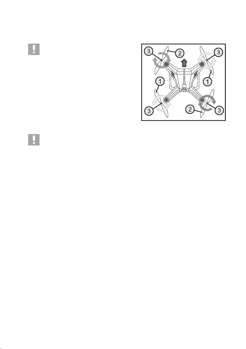
b) Assembly of the Propellers
The quadrocopter comes with 1 pair of left-turning propellers (1) and 1 pair of right-turning propellers (2) each.
Important:
Observe the rotating direction of the propellers at in-
stallation. The propellers at the front left and the rear
right turn clockwise when viewed from above; the
propellers on the front right and rear left turn counter-
clockwise (see rotating direction arrows in gure 2).
In addition to the motors, circular arrows are placed on the top of
the housing to indicate the rotating direction precisely.
The arrow in the upper half of the picture shows the ight direction of the model forwards.
Figure 2
Attention!
The propellers have glued-in attachment nuts (see gure 2, item 3), which tighten when the quadrocopter is
in operation.
To attach the propellers, place the respective propellers on the threads of the motor shafts and manually turn
the propellers contrary to the regular operating rotating direction. Hold the bell of the brushless motor with
the other hand.
Wear protective gloves when installing the propellers to avoid injury from the thin and sharp-edged propel-
lers.
Do not over-tighten the propellers and do not use any threadlocker varnish or glue to secure the propel-
lers.
If a propeller is damaged (cracks or small pieces broken out), replace the defective propeller without delay.
Do not continue to use defective propellers.
Stay away from turning propellers to avoid accidental injury.
If the propellers must be replaced, use only the spare propellers provided by the manufacturer.
12
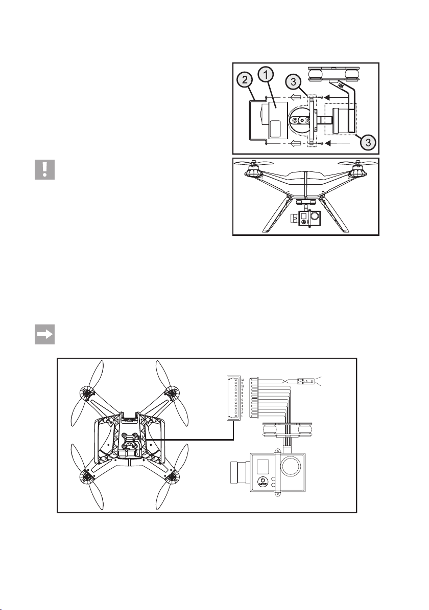
c) Stabilised Camera Holder (2 D-Gimbal)
The quadrocopter has a camera holder stabilised around two
axes (gimbal) installed already. Once the ight battery at the
quadrocopter is switched on, the holder will automatically align
and compensate any nod and roll movements of the quadro-
copter in ight.
To install a camera of type GoPro or other corresponding cameras (1), the holding bracket (2) must be removed and attached
again with the two M2 x 5 screws after inserting the camera. The
required screwdriver is enclosed with the quadrocopter.
Caution, important!
The two transparent plastic covers (3) that are pushed
onto the camera holder from the rear and from the side
only serve to protect the gimbal when transporting the
quadrocopter. The covers must be removed before in-
serting the ight battery or the camera. Otherwise, the
gimbal cannot perform the required movements and is
thus destroyed!
Never operate the camera holder without a camera
inserted. The missing weight of the camera will cause
the holder to be unbalanced, which will put too much
of a strain on the controlling electronics, which may be
damaged.
If the camera holder must be removed from the quadrocopter, disconnect the 12-pin plug connector from the corresponding connection in the quadrocopter. The camera holder itself is attached to the quadrocopter with four screws.
The two-pin plug with the red/black cable is used to supply power to an optional video signal transmitter
(red = +12 V/DC, black = GND). Hook-and-loop tape for attaching the video transmitter is enclosed with the
quadrocopter.
Figure 3
Figure 4
GND
+12 V/DC
13
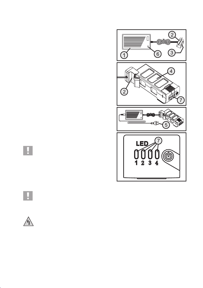
d) Charging the Flight Battery
The 3-cell ight battery is charged using the enclosed mains unit
(1) supplied. For this, open the cover of the charge adapter (2),
so that the two large charging contacts (3) are visible.
Connect the ight battery (4) to the charge adapter according to
the two middle illustrations in gure 5.
After connecting the enclosed mains cable to the mains unit,
connect the mains plug (5) to a proper mains socket of the public
mains.
The indicator lamp at the mains unit lights up red to signal that
charging is in progress. At the same time, the four LEDs at the
ight battery (7) indicate the current charge condition.
When the ight battery is discharged, only LED 1 is lit. With
increasing battery charge, LED 2 rst starts to ash and then
remains lit. This display will also be repeated in LED 3 and LED
4 as charging continues. Before charging is complete, all 4 LEDs
will be permanently lit.
When the ight battery is fully charged, the four LEDs at the
ight battery (7) will go out and the control indicator at the mains
unit (6) will light up green.
Once charging is completed, disconnect the ight battery from
the charge adapter and pull the mains plug from the mains socket.
The connection cable of the charge adapter is shown
coiled for better illustration in the drawings in gure 5.
Before the rst charging process, however, you need
to remove the cable tie and use the charge adapter
cable in the uncoiled condition.
Figure 5
Attention!
During the charging procedure, place the LiPo battery on a re-proof support or in an appropriate clay
vessel.
Never charge the battery unobserved.
The mains unit/mains cable is to be used in dry indoor locations only. It must never get damp or wet. Never
touch them with wet or damp hands. There is the risk of a potentially fatal electric shock!
14
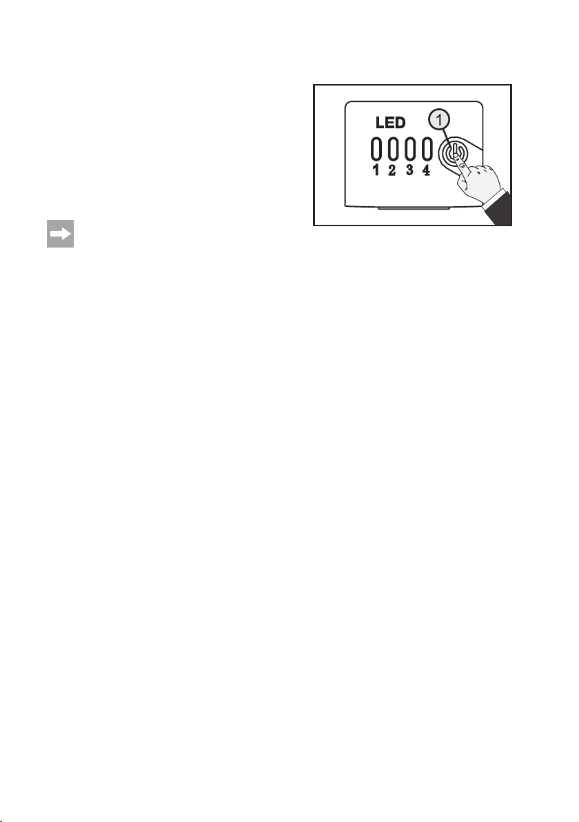
e) Testing the Rechargeable Battery Charge Condition
The current charge condition of the ight battery can be tested
easily at any time.
For this, briey push the on/off button (1) at the ight battery. For
approx. two seconds, the four LEDs show the current charge
condition.
When the ight battery is discharged, only LED 1 will be lit; if it
is fully charged, all four LEDs will be lit. At a partially discharged
ight battery, e.g., LED 1 and LED 2 would be permanently lit
and LED 3 may ash.
The display of the rechargeable battery voltage above
the four LEDs only serves as a general indication. The
precise battery voltage can be read in operation of the
quadrocopter at the transmitter display if necessary.
Figure 6
15
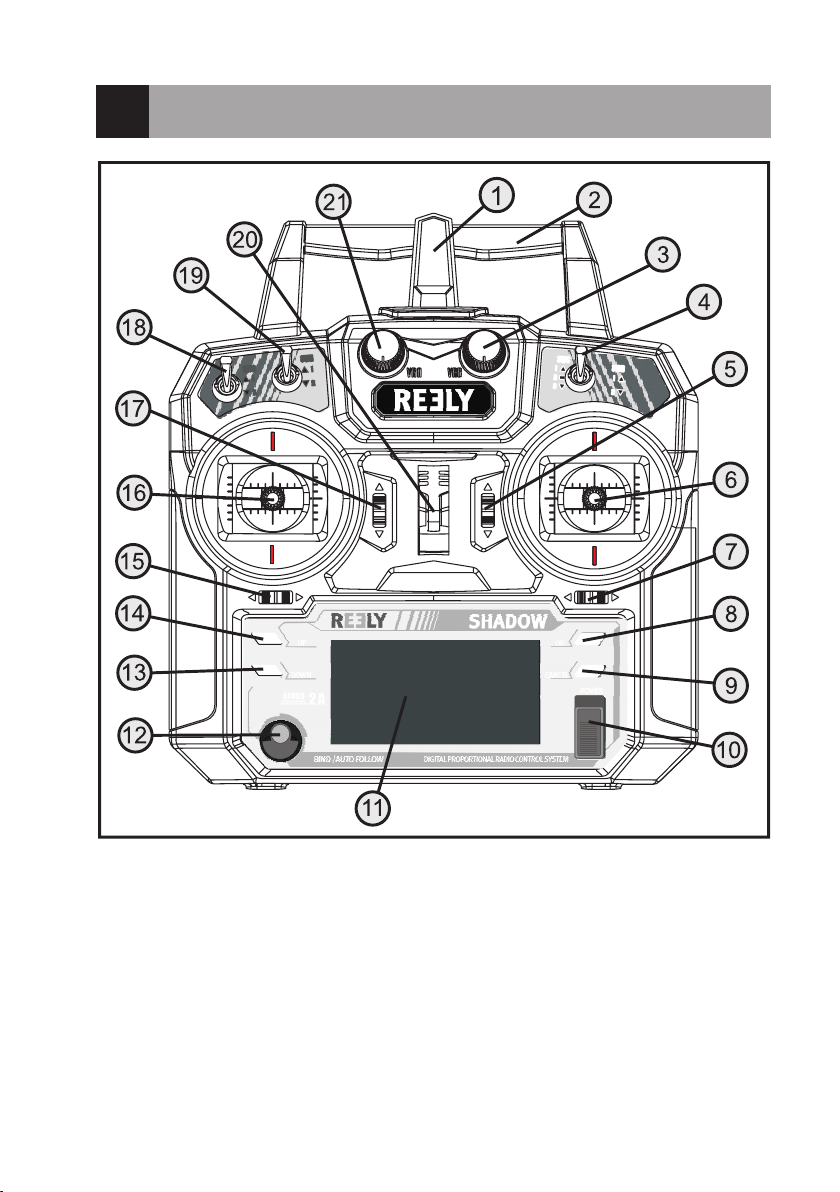
9. Transmitter Controls
16
Figure 7
Front (gure 7):
1 Transmitter aerial
2 Carry handle with integrated second transmitter aerial
3 Rotary encoder „VRB“
4 Toggle switch „GPS“
5 Trim button for nod function
6 Control stick for nod and roll functions
7 Trim button for roll function
8 „OK“ button
9 Button „CANCEL“
10 On/off switch
11 LC display
12 „BIND/AUTO FOLLOW“ button
13 „DOWN“ button
14 „UP“ button
15 Trim button for yaw function
16 Control stick for the yaw and pitch functions
17 Trim button for pitch function
18 Toggle switch „IOC“
19 Toggle switch „GO-HOME“
20 Eyelet for shoulder belt
21 Rotary encoder „VRA“
Rear (gure 8):
22 GPS receiver connection socket
23 Battery compartment lid
Figure 8
17
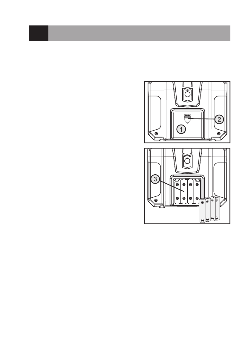
10. Setting up the Transmitter
a) Inserting the Batteries
For the power supply of the transmitter you will need 4 alkaline batteries (e.g. Conrad item no. 652507, pack of 4,
order 1) of the size AA/mignon.
Proceed as follows to insert the batteries:
The battery compartment lid (1) is located on the back of the
transmitter. Press the corrugated area (2) and push off the lid
downwards.
Ensure that the polarity is correct when inserting the 4 batteries.
A corresponding note (3) is located on the bottom of the battery
compartment.
Then slide the lid of the battery compartment back on from the
bottom until the locking mechanism engages.
Figure 9
b) Switching on the Transmitter
After you have inserted four new batteries, check the position at the toggle switches. All switches must be in the front/
top position. The two control sticks are held in the middle position by spring power. Now switch on the transmitter using
the on/off switch (see g. 7, item 10).
First, three signals sound in increasing altitude and the backlit display shows the operating display. The backlighting
is deactivated automatically about 20 seconds after activation or the last button operation.
If no operating element is operated within 60 seconds with the transmitter on, the transmitter will emit short signal
sounds as a warning.
18

The operating display consists of the following elements:
1 Model name
2 Model type gure
3 Battery symbol for transmitter voltage supply
4 Battery symbol for receiver voltage supply
5 Nod trimming display
6 Roll trimming display
7 Information area for status messages
8 Yaw trimming display
9 Distance display in „Following-Mode“
10 Pitch trimming display
11 Display for GPS reception of the transmitter*
* The display only appears when the GPS receiver has been connected to the transmitter.
If one of the three toggle switches (see gure 7, item 4,
18 and 19) is not in the front position, warning sounds
will be emitted when activating and the corresponding
note is displayed (see gure 11).
In this case, the affected switches must be put in the
required position. The display then switches to the
operating display and the warning sounds go out.
Figure 10
Figure 11
19

The operating display shown in gure 10 will only appear completely if the receiver system or quadrocopter is in operation as
well.
Pushing the button „UP“ or „DOWN“ calls two more display windows alternatingly.
The rst window shows the following information:
• Flight altitude „Altitud“
• Flight battery voltage „Voltage“
• Number of received satellites „Satelli“
• Flight speed „Speed“
The second windows shows the following information:
• Geographic longitude „Lon“
• Geographic latitude „Lat“
• Flight mode
• „GPS Mode“
Example in gure 12:
The two upper gures show the displays without GPS reception
of the quadrocopter. The two lower ones represent a display with
GPS reception.
Figure 12
If the power supply is not sufcient for correct transmitter operation anymore, the battery icon will ash at a
voltage of less than 4.2 V and the transmitter emits acoustic warning sounds at regular intervals. The model
should then no longer be operated.
When the voltage drops below 4.0 V, the transmitter emits alarm sounds without interruption. In this case,
operation of the model must be ceased as quickly as possible. Insert new batteries for further operation of
the transmitter.
20

c) Setting the Control Stick Length
You can adjust the length of the control sticks, depending on
your steering habits.
To do so simply hold the bottom part of the grip (1) and turn the
upper part (2) up anti-clockwise.
You can now set the length of the control stick by turning the
bottom part of the grip.
Finally, tighten the upper part of the grip back up.
Figure 13
21

11. Commissioning of the Quadrocopter
Before you start the quadrocopter for the rst time, read this section with care. Only if you are absolutely
certain that you have made all settings correctly must you start the motors and let the quadrocopter lift off.
Otherwise, contact an experienced model pilot who can support you in initial commissioning. We recom-
mend using a ight simulator where you can train your rst ight tasks without danger.
a) Checking Activation/Deactivation function of the Flight Battery
Before inserting the ight battery in the quadrocopter, check the activation/deactivation function of the electronics in
the ight battery.
Switching on
To switch on the ight battery, briey push the on/off button (1)
at the ight battery and release it again at once. When the ight
battery is fully charged, the four LEDs of the ight battery will
start to light up.
Now push the on/off button (1) again and keep it pushed. The
four LEDs will go out and start to light up again in sequence
(LED 1 to LED 4).
When all four LEDs are lit, release the button again. The ight
battery is now on and voltage is pending on the rechargeable
battery contacts.
Switching Off
Briey push the on/off button (1) at the ight battery with the
ight battery switched on and release it again at once. The four
LEDs of the ight battery will start to ash three times.
During this time, push the on/off button (1) again and keep it
pushed. The four LEDs will be lit and then go out in sequence
(LED 4 to LED 1).
When LED 1 has gone dark as well, release the button again.
The ight battery is now off and the battery contacts are powered down.
Figure 14
Figure 15
22

b) Inserting the Flight Battery into the Quadrocopter
To ensure a sufciently good satellite reception, the quadrocopter should be set up on a free eld, where no high-
voltage lines, power masts, metal constructions or other obstacles may impair GPS reception.
Stay away from broadcasting systems and other facilities that may negatively inuence the electromagnetic conditions
in your environment.
The ight eld should also be free of obstacles such as buildings or trees to ensure unimpaired ight operation.
Choose a day with good whether and the least possible wind.
Before inserting the ight battery in the quadrocopter, check the voltage situation. For this, briey push the on/off
button (1) at the ight battery. All four LEDs must be lit for two seconds.
Switch on the remote control transmitter and check the correct function of the transmitter with the display. The trim-
ming displays (see gure 10, items 5, 6, 8 and 10) must be in the middle position. If this is not the case, the trimming
must be set (see the following chapter 11. g).
Turn the rotating encoder „VRB“ to the centre position or check the centre position of the controller.
Now push the deactivated ight battery (see gure 16, item 1) into the quadrocopter with the charge connection contacts rst. Slightly push the grooved surface of the battery lock (see gure 16, item 2) so that the locking tab can latch
and the ight battery is safely held in the quadrocopter.
When the ight battery has been inserted into the quadrocopter and is locked properly, switch on the ight battery with
the on/off button (see gure 6, item 1), so that the quadrocopter is supplied with power
Figure 16
The status LEDs (see gure 16, item 3) light up yellow (red and green) and the quadrocopter performs a self-test. After
a brief time, the downward-pointing LEDs in the book arms will ash and the quadrocopter will emit a brief signal.
The gimbal swivels the camera holder into the home position and the status LEDs will briey go out and then start to
ash. The meaning of the ashing impulses is described in more detail below.
When the binding between the transmitter and receiver is correct, the display of the remote control shows the voltage
supply of the receiver (see gure 10, item 4). Push the buttons „UP“ or „DOWN“ at the transmitter to get more information about the current reception of the GPS satellite.
23

c) Calibration of the Compass
The quadrocopter has a compass with the help of which it can
control the ight direction and ight altitude.
Before the quadrocopter can be started, the compass must be
calibrated. We recommend calibration before each ight.
After a site change to another starting position, the compass
must be calibrated.
To calibrate the compass in the free eld, proceed as follows:
• Switch the toggle switch „GPS“ 5 times quickly from the front
position (position 1) to the rear position (position 2) and back.
The status LEDs at the quadrocopter must be permanently lit
yellow (red and green).
• Hold the quadrocopter horizontally (see gure 17, illustration
A) and turn it around its vertical axis until the status LEDs
switch to green (at least 360°).
• Then hold the quadrocopter with the front propellers vertically
down and turn it 360° around the longitudinal axis (see gure
17, illustration B), until the status LEDs go out.
• Calibration is complete.
• Return the quadrocopter to the normal position.
• After a brief time, the status LEDs will ash according to the
GPS satellites received.
• If the status LEDs ash red and yellow, calibration was defective and must be repeated.
Figure 17
24

d) Basic Information Relevant to the Control of Quadrocopters
Before you let your model lift off for the rst time, you should rst familiarise yourself with the control possibilities open
to you and thereby be able to y safely.
The quadrocopter is controlled via the two control sticks at the remote control transmitter. Ex works, the control functions of the two sticks are programmed to „mode 2“.
If you want different control stick assignments, you can adjust them at any time. For further information on the control
stick assignment, see the chapter „Programming the Remote Control Transmitter“.
Control stick assignment „Mode 2“ offers the following functions:
Pitch Function
With the pitch function you can control the ight altitude of the quadrocopter (see gure 18). The left control stick (also
see gure 7, item 16) is used for control. In contrast to other remote control systems, where the control stick for the
pitch function can be moved forward and back without springing back to the middle position, the pitch control stick has
a middle position in the quadrocopter „Shadow“ in which it is held by spring force.
If the control stick for the pitch function is moved from the middle position upwards, the quadrocopter will climb. If it s
deected from the middle position downwards, the quadrocopter will sink.
Every time the control stick is returned to the middle position, the remote control will emit a signal sound.
Once the control stick is in the middle position, the propeller speeds should be high enough for the quadrocopter to
hover.
Figure 18
25

Yaw Function
The two right-ward turning and the two left-ward turning propellers balance out the torques acting on the model. The
quadrocopter hovers stably.
If the control stick for the yaw function (also see gure 7, item 16) is moved to the left, he electronics in the model will
increase the speed of the propeller turning to the right (clockwise) and at the same time rescue there speed of the
propellers turning to the left (counter-clockwise). This way, the entire lift force remains the same, but only one torque
acts on the model, which turns the quadrocopter around its vertical axis to the left (see gure 19).
If the control stick is moved to the right, the speed changes of the propellers are precisely the other way around and
the model turns to the right.
Figure 19
26

Roll function
The roll function allows you to move your quadrocopter sideways to the right and to the left (see gure 20). Use the
right control stick for control (also see gure 7, item 6).
If the stick is slightly moved to the left, the electronics in the quadrocopter change the propeller speeds so that the
model will turn to the left slightly and thus also y to the left.
If you move the transmitter to the right, the speed changes of the propellers are precisely inverted and the model will
y sideways to the right.
Figure 20
27

Nod Function
The nod function allows you to move your quadrocopter forward and backward (see gure 21). This is also controlled
with the right control stick (also see gure 7, item 6).
If the stick is slightly pushed to the front, the electronics in the quadrocopter change the propeller speeds so that the
model will turn to the front slightly and thus also y forward.
If you move the transmitter to the rear, the speed changes of the propellers are precisely inverted and the model will
y to the rear.
Figure 21
28

e) Setting the Toggle Switch
Before letting your model lift off for the rst time, check the switch
positions of the three toggle switches „IOC“ (also see gure 7,
item 18), „GO-HOME“ (see gure 7, item 19) and „GPS“ (also
see gure 7, item 4).
The switches must be in the front or upper position according to
the drawing in gure 22.
In this switch combination, the quadrocopter ies GPS-stabilised.
This switch position is ideal for the rst test ights outdoors.
If the quadrocopter is to be used indoors (e.g. in a hall or apartment, etc.), the switch „GPS“ must be put in the bottom position
„GPS“ off).
Since operation indoors does not have GPS support, beginners and inexperienced model pilots should
initially only operate the quadrocopter outdoors and with GPS support.
For more information on this, see the following chapter 12.
The switches have the following functions:
Figure 22
Switch position
front/top
Switch „IOC“ „IOC“ off „POI-Mode“ „Home Lock-Mode“
Switch „GO-HOME“ „Go-Home“ off - „Go-Home“ on
Switch „GPS“ „GPS“ on - „GPS“ off
For a precise description of the individual functions, see chapters 12 to 14.
Switch position
Middle
Switch position
rear/bottom
29

f) Starting the Quadrocopter
• Stand behind the quadrocopter.
• The quadrocopter should point at you with the voltage display of the ight battery (four LEDs).
• Check the voltage display of the ight battery and the remote control transmitter, as well as the position of the toggle
switches (position front/top).
• Wait until the quadrocopter receives more than six GPS satellites and has saved the starting point. The status LEDs
will then ash green approx. every 5 seconds. Now your quadrocopter is ready to start.
• Move the left control stick to the lower right and at the same
time the right control stick to the lower left (see gure 23).
• Once the motors start up, return both control sticks to the
middle position again without delay.
• The LEDs pointing down on the front boom arms are white and
the LEDs pointing down on the rear boom arms are red.
Important!
Never move both control levers at once to start the
motors while the quadrocopter is hovering or standing
on the ground with the motor running. The quadrocopter would crash with standing propellers or tip backwards on the ground and take damage.
• Push the control stick for the pitch function slowly to the front. The quadrocopter increases the propeller speed and
lifts off.
• When you return the control stick to the middle position, the quadrocopter will hover.
Important:
Do not deect the control stick for the pitch function too much; otherwise, the quadrocopter will rise very
quickly or drop too quickly.
Never try grabbing the ying quadrocopter with your hand. There is a considerable danger of injury.
• Perform the rst careful direction controls at an altitude of 1 - 2 m and observe how the quadrocopter reacts to the
control commands.
• To land the quadrocopter again, pull the control stick for the pitch function from the middle position back a bit for the
quadrocopter to slowly reduce ight altitude and land.
• When the quadrocopter has touched down, pull the control lever for the „pitch“ function all the way to your body and
keep it in this position. Once the motors have been switched off and the propellers are no longer turning, put the
control lever back into the middle position.
Attention!
Always keep an eye on the 4 LEDs of the voltage indication of the ight battery while ying. With increasing
ight length, LED 4 will start ashing rst and then go out. This repeats with LED 3 and LED 2.
At the latest when only LED 1 is lit anymore you should start landing without delay. If this is not done, the
quadrocopter will initiate a landing on its own to avoid harmful deep discharge of the ight battery. The status
LEDs at the quadrocopter start to ash red.
As an alternative to the rechargeable battery LEDs, which offer only a general indication in the end, you can
read the current voltage of the ight battery much more precisely in the transmitter display.
Figure 23
30

g) Trimming the Quadrocopter
When operating the quadrocopter indoors (e.g. in a hall) or in
manual mode („GPS“ off), the quadrocopter may y into a specic direction in spite of both control sticks being in the middle
positions.
If the quadrocopter drifts to the right when hovering, push the
trim button for the roll function (also see gure 7, item 7) to the
left until the quadrocopter stops trying to drift to the right.
The remote control emits a short signal sound for each press of
a trim stick. The tone height depends on the trimming direction.
The middle position is acoustically indicated by a longer signal.
The set value is automatically saved and is retained even after
switching the transmitter off and on.
The other three control functions can be set with the trim but-
tons (see gure 24, items 5, 15 and 17) according to the same
scheme as required.
Figure 24
31

h) Overview of the Flashing Displays of the Status LEDs
After switching on the transmitter and the ight battery in the quadrocopter, the quadrocopter will perform a self-test in
which it checks, among others, binding with the transmitter. During this time, the status LEDs will light up yellow*. Do
not move the quadrocopter during this period.
If the self-test of binding with the transmitter was defective, the status LEDs will ash green slowly.
If the self-test or binding with the transmitter was successful, the following displays of the status LEDs depending on
the position of the switch „GPS“.
In „manual mode“ (the switch „GPS“ is in the rear/bottom position), the status LEDs ash yellow* once and red 4 x
after two seconds. This ashing rhythm repeats continually.
In „GPS mode“ (the switch „GPS“ is in the top/front position), the status LEDs ash yellow once and red several times
after two seconds. When 4 or more GPS satellites are received, the status LEDs ash green and red.
The number of red ashing impulses shows the number of satellites received:
4 red ashing impulses: Insufcient GPS reception (ight not possible in „GPS mode“).
3 red ashing impulses: 4 GPS satellites received.
2 red ashing impulses: 5 GPS satellites received.
1 red ashing impulse: 6 GPS satellites received.
No red ashing impulses: 7 or less GPS satellites are received. The LED display ashes only green every 5 se-
The more satellites are received, the more precise will the automatic positioning of the quadrocopter in ight
be.
• The quadrocopter has a xed warning threshold that protects the ight battery from deep discharge. If the voltage of
the ight battery drops below the warning threshold, the quadrocopter will land on its own and the status LEDs will
ash red quickly.
• When the quadrocopter no longer receives any remote control signal, the status LEDs will ash green quickly.
• When the quadrocopter is in a ight prohibition zone, the status LEDs will ash 10 x with a subsequent pause of 2
seconds. This ashing scheme is repeated continually.
• When the quadrocopter is in an electromagnetically complex environment with interference signals, the status LEDs
remain lit red.
• When the quadrocopter has successfully saved the ight alignment, the status LEDs ash green quickly 20 x.
• When the quadrocopter has successfully saved the starting point, the status LEDs ash red quickly 20 x.
• When the quadrocopter has successfully saved the point of interest, the status LEDs ash yellow* quickly 20 x.
conds.
* To display the colour yellow, the red and green LEDs of the status display will light up together. Since the LEDs
are not placed very closely together, the yellow light effect is not quite as well recognisable as the red or green
display.
32

12. Overview of the Flight Modes
The quadrocopter has different ight modes that can be activated by toggle switch.
a) „Manual-Mode“
„Manual-Mode“ is suitable for indoor shows where it is not possible to receive a GPS signal for constructional reasons.
The quadrocopter can be controlled in all directions but there are no automatic corrections of the light position, since
the quadrocopter has no GPS information.
b) „GPS-Mode“
The „GPS-Mode“ is ideal for the rst ight attempts outdoors, where best GPS reception is possible. The quadrocopter
can be steered in all directions, and the ight position is corrected automatically. This means: The quadrocopter will
automatically maintain the last position/altitude when the control sticks at the transmitter are in their middle positions.
In „GPS mode“, the „IOC“ function („Intelligent Orientation Control“) can be activated.
c) „IOC“ Function (Smart Flight Orientation)
Without „IOC“ function (= „Intelligent Orientation Control“), the movement directions always refer to the build of the
quadrocopter. The side with the status LEDs is front. Looking at the quadrocopter from above, e.g. a control command
forward will always move it in the direction in which its front is aligned (no matter which direction the front of the quadrocopter is currently pointing in).
This may lead to problems when the quadrocopter, e.g, points to the pilot with its front (status LEDs). Now the quadrocopter will move in the opposite direction of the one the pilot steers it in at the transmitter from his point of view.
Figure 25
33

When the „IOC“ function has been activated, the movement directions of the quadrocopter no longer refer to its build.
The movement direction of the quadrocopter changes depending on which mode is called within the „IOC“ function.
Important!
The „IOC“ function requires concurrent reception of more than 6 GPS satellites and the quadrocopter must
be more than 5 m away from the starting point. Then, a total of three modes are available:
• „CL Mode“ (= „Course Lock“)
• „HL-Mode“ (= „Home Point Lock“)
• „POI-Mode“ (= „Point Of Interest“)
Attention!
When the quadrocopter is in „IOC-Mode“ and ies farther away, do not push the „IOC“ switch repeatedly
since this will overwrite saved values and, e.g, the „return home“ point will be in an entirely different location
(also see chapter 13).
d) „CL-Mode“
In „CL-Mode“ (= „Course Lock“), the quadrocopter uses its installed compass to measure its alignment. When the
quadrocopter has been aligned e.g. with a far-distance church tower with its front before the start, it will always y
towards the church tower when steering forward at the transmitter. This applies even if the quadrocopter has been
turned around during the ight and its front points in any other direction.
34
Figure 26

e) „HL-Mode“
In „HL-Mode“ (= „Home Point-Lock“), the movement direction of the quadrocopter always refers to the line from the
starting point (HP) in the direct proximity of which the pilot is placed as well, and the quadrocopter. Independently of
the direction in which the front of the quadrocopter is aligned, it will always y in the direction in which the pilot steers
at the transmitter from the pilot‘s point of view. This mode has a safe distance of at least 5 m from the starting point in
which the „HL mode“ cannot be activated or that the quadrocopter maintains automatically when ying.
Figure 27
f) „POI-Mode“
In „POI-Mode“ (= „Point Of Interest“), the movement direction of the quadrocopter refers to a freely selectable point in
the terrain with which the quadrocopter is aligned with its front. By steering to the right and left, you can choose the
direction and speed in which the quadrocopter circles around the point in the terrain. Steering forward (closer to the
„POI“) and backward (farther away from the „POI“) inuences the radius of the ight track. The possible radius around
the „POI“ is 5 - 500 m.
Figure 28
35

13. Activating the Flight Modes
The „IOC“ function is activated and deactivated with the „IOC“ switch, which also switches the respective ight modes.
The switch can be assigned with 3 combination options on demand. Ex works, the switch „IOC“ is occupied according
to the combination C in the following table.
Switch „IOC“ Switch position
front/top
Combination A „IOC“ off „CL-Mode“ „HL-Mode“
Combination B „IOC“ off „CL-Mode“ „POI-Mode“
Combination C „IOC“ off „POI-Mode“ „HL-Mode“
If you want to use „CL-Mode“, the quadrocopter must be reprogrammed to the switch combination A or combination
B.
The assistance software needed for this is available for download free of charge online on the respective product
page of www.conrad.com. The interface cable for connection of the quadrocopter to the computer is already enclosed
with the quadrocopter.
For the quadrocopter to be able to activate the different „IOC“ modes, it must record and save the alignment, the
„home point“ or the „point of interest“. This is partially done automatically or can be performed manually.
„CL-Mode“
The mode is only available if the switch „IOC“ has been reprogrammed to the combination A or B.
The alignment of the quadrocopter is automatically recognised 36 seconds after plugging in of the ight battery. More
than 6 GPS satellites must be received.
To manually save the alignment, the switch „IOC“ must be switched back and forth between the front/upper and the
middle position 3 - 5 times.
When the alignment has been saved successfully, the status LEDs ash green quickly 20 x.
„HL-Mode“
The mode is only available if the switch „IOC“ has been programmed to the combination A or C.
The point where the control stick for the pitch function has been pushed forward for the rst time and the quadrocopter
lifted off is saved as the starting point automatically.
The prerequisite for this is reception of more than 6 satellites for a period of at least 10 seconds.
To manually save another starting point, the switch „IOC“ must be switched back and forth between the middle and
the rear/lower positions 3 - 5 times.
When the starting point has been saved successfully, the status LEDs ash red quickly 20 x.
Switch position
Middle
Switch position
rear/bottom
36

„POI-Mode“
The mode is only available if the switch „IOC“ has been programmed to the combination B or C.
The „point of interest“ can only be saved manually. The prerequisite for this is reception of more than 6 satellites for
a period of at least 10 seconds.
To manually save the „point of interest“, the switch „IOC“ must be switched back and forth between the front/upper and
the middle position in combination C 3 - 5 times.
In combination B, the switch „IOC“ must be switched back and forth between the middle and the rear/lower positions
3 - 5 times.
When the „point of interest“ has been saved successfully, the status LEDs ash yellow quickly 20 x.
14. „Go-Home“ Function
The quadrocopter has a „Go-Home“ function that returns the quadrocopter to the starting point automatically or by
remote control command. The prerequisite for this function is that the starting point has been saved (see „HL-Mode“)
and that the quadrocopter is ying in „GPS-Mode“ and receives more than 6 GPS satellites. The distance between
the quadrocopter and the saved starting point must be more than 5 m as well.
When the switch „Go Home“ is put in the rear/lower position for the return function, the quadrocopter will turn more
or less and hover for approx. 3 seconds.
When the quadrocopter is below a ight altitude of 20 m, it will rst climb to 20 m before ying back over the saved
starting point. If it is at a ight altitude above 20 m, it will return to the starting point at once.
Figure 29
37

When it is above the saved starting point, it will quickly reduce the ight altitude to 5 mm and hover for 3 - 5 seconds
before nally slowly reducing the remaining ight altitude until touching down.
Figure 30
Attention!
The „Go-Home“ function is tripped automatically when the quadrocopter no longer receives any valid remote
control signal. With the assistant software, which is available as a free download in the Conrad-Shop with
the product, you can set if the quadrocopter is to perform the „go-home“ function or hover in place when it
loses contact.
Important:
When the quadrocopter receives fewer than 6 satellites or is not in „GPS-Mode“, the „Go-Home“ function is
no longer available.
If the quadrocopter is in a difcult to control situation or very far away from the pilot‘s site, activate the return
function with the „Go-Home“ switch. Never switch off the transmitter.
Observe obstacles that may be in the way during the automatic return ight. The quadrocopter does not
have any automatic obstacle recognition.
When the quadrocopter has landed, switch off the drive motors.
38

15. „Following“ Function
For the quadrocopter to be able to follow the remote control, the
transmitter also must be equipped with a GPS receiver (see gure 31, item 1). The installation of the GPS receiver on the remote
control can be taken from the above illustration in gure 31.
The connection plug (see gure 31, item 2) of the GPS receiver
is connected to the rear of the remote control.
If the transmitter with the connected GPS receiver is switched
on, the satellite display at the left of the display ashes (see
gure 10, item 7). If more than 7 satellites are received, the dis-
play remains lit.
Then take the quadrocopter into operation, calibrate the compass and then switch it to „GPS-Mode“.
Start the quadrocopter and y it to the desired position in which
it is to follow the remote control transmitter.
When the quadrocopter is in the desired position, push the button „BIND/AUTO FOLLOW“ (3). The quadrocopter will now align
with the transmitter and follow any movement of the transmitter
in the same altitude and at the same distance.
To end the following function, push the button „BIND/AUTO
FOLLOW“ again and land the quadrocopter.
Caution, important!
The quadrocopter cannot recognise obstacles. It will always maintain the same distance and altitude as
compared to the transmitter. It does this even if there are, e.g., trees or other obstacles in the way. Observe
this when working in „following mode“.
Figure 31
39

16. Undervoltage Warning
The quadrocopter checks the voltage of the ight battery continually in ight. The current voltage can be read in the
remote control‘s display if required (see upper illustration in gure 12). However, the voltage values are displayed with
a delay due to the data transmission.
If the voltage drops below the xed value set ex works, the status LEDs at the quadrocopter will ash red quickly and
the quadrocopter will land automatically. The remote control will emit continuous warning sounds and the display will
show a ashing warning message. To switch off the warning messages, you need to switch the transmitter off and on
again after switching the quadrocopter off.
Even if the ight direction can still be controlled within limits during independent landing, we recommend not
to y this long. Observe the voltage display at the ight battery and the transmitter and land in time.
17. Failsafe Function
The failsafe function protects the quadrocopter from crashing when it receives no valid remote control signal anymore.
In the assistant software, you can set how the quadrocopter is to behave if the transmitter signal fails. The automatic
ight control system in the quadrocopter can let it hover in place or return to the starting point and land there.
The failsafe function will, however, only work when GPS data are available. Otherwise, the quadrocopter can only try
to stabilise the ight position and to maintain the altitude.
For more information on the failsafe function, see the assistant software.
40

18. Flight Space Limitation and Flight Prohibition Zones
The quadrocopter has a distance and altitude limitation that can be set individually with the assistant software. Ex
works, a maximum ight altitude of 120 m and a max. distance of 300 m are set.
If the distance limit is exceeded by more than 10 m, the quadrocopter will automatically return to the starting point.
Compliance with the max. distances only works, however, if the quadrocopter is operated in „GPS-Mode“ and has
enough satellite reception.
The quadrocopter also considers ight prohibition zones. Flight prohibition zones are areas in direct proximity to
airports, military systems and other protection-worthy facilities. The quadrocopter has a digital map in which these
zones are shown. In connection with its intelligent orientation function, the quadrocopter can tell when it enters a ight
prohibition zone if in „GPS-Mmode“. In this case, the status LEDs will ash red 10 x.
If the ight prohibition zone has been entered, the quadrocopter will no longer react to the ight altitude control. The
other control functions are fully retained. The quadrocopter reduces the ight altitude automatically with a dropping
rate of approx. 3 m/s until it either lands automatically or is steered from the ight prohibition zone.
Attention!
Compliance with ight prohibition zones can be switched off and on in the assistant software. We urgently
recommend not switching off this function, however.
41

19. Gimbal Control
The camera holder that is stabilised around two axes (gimbal) compensates for the nod and roll movements of the
quadrocopter and thus ensures a calm camera image.
Additionally, the camera can be swivelled from the horizontal position vertically up by 45° and down by 135°. The
swivel movement is controlled with the rotary controller VRB (1).
Figure 32
Caution, important!
Never operate the camera holder without a camera inserted. The missing weight of the camera will cause
the holder to be unbalanced, which will put too much of a strain on the controlling electronics, which may be
damaged.
42

20. Binding Function
Transmitter and receiver in the quadrocopter are already aligned with each other (bound) in the factory and can
be used at once. Renewal of binding is only required after replacing the receiver in the model, when replacing the
transmitter or to remove a malfunction, e.g. when the receiver parameters are no longer displayed in the transmitter
display.
Attention!
When the transmitter is reset to the factory settings, the binding must be renewed, since the receiver ID has
also been deleted.
Re-establishing the binding:
To recover binding between the transmitter and model, the four propellers must be removed and the top of the housing
of the quadrocopter must be screwed off. For this, the landing frame must be removed and the 20 screws at the bottom
of the housing turned out.
The four screws below the motors do not need to be removed, since these screws only hold the motors.
• Transmitter and receiver must be in direct proximity (distance
approx. 50 cm).
• Switch off the transmitter.
• Disconnect the two plug connectors (1) with which the quadro-
copter is connected to the receiver from the receiver.
• Connect the enclosed programming plug (2) to the „B/VCC“
connection of the receiver with the cable loop.
• The receiver must be supplied with power via a receiver battery that is connected to any output of the receiver (3). Ensure
correct polarity. The minus connection (-) must be at the bottom.
• Switch on the receiver. The red LED in the receiver (4) starts
to ash quickly.
• Push the button „BIND/FOLLOW“ (5) at the transmitter and
keep it pushed.
• Switch on the transmitter with the on/off switch (6) with the binding button pushed. Then release the „BIND/FOLLOW“ button
at the transmitter.
• The display briey shows „RXBinding“ and, at correct binding, „RXBind OK“. Then the display switches to operating
display.
• The red LED in the receiver remains lit and binding is completed. If the LED ashes red, binding was not successful
and must be repeated.
• Switch off the receiver and then the transmitter.
• Remove the programming plug and connect the two plugs of the quadrocopter to the receiver again.
Figure 33
43

• Check the function of the system.
The receiver now must react to the control signals of the transmitter. If this is not the case, repeat binding or
check the digital encoding of transmitter and receiver.
21. Programming the Remote Control
Your remote control offers a system setting menu „System setup“ and a function setting menu „Functions setup“ with
different menu items in each. This way, you can make general settings or review functions at the transmitter.
The changes of the respective settings are made with the four
programming buttons (also see gure 7, items 8, 9, 13 and 14).
The settings are permanently saved and are retained even when
changing the batteries.
The functions of the operating elements:
„OK“ button
To call the programming menus, briey push the button „OK“ with the transmitter on. The displayed operating display
switches to the menu display and the transmitter switches to programming mode. This button can also activate selected settings. If the button is pushed or longer, the factory settings stored in the menu item are called.
„CANCEL“ button
This button allows you to leave the currently selected menu or submenu again. Every brief push of this button takes
you a step back until you reach the operational display. If the button is kept pushed for a while, the changed set values
are stored.
„UP“ and „DOWN“ buttons
The two buttons can be used to select the desired menu/submenu or change set values.
The transmitter emits a short signal sound for each permissible push of a button.
Figure 34
44

22. The System Setting Menu „System Setup“
The basic settings of the remote control transmitter are made in
the system setup menu rst.
To get to the system settings menu, push the button „OK“ with
the transmitter switched on. The operating display in the display
switches to the menu display. The selection window around the
remote control icon shows that you can call the „System Setup“
menu in this setting.
Briey push the button „OK“ again to get to the system settings
menu.
The 5 menu items of the system setting menu are now displayed.
The following setting functions are available for you in the system setting menu:
Function Display
Control stick assignment „Sticks mode“
Display brightness „LCD brightness“
Transmitter software version „Firmware ver.“
Transmitter software update „Firmware update“
Factory reset „Factory reset“
Figure 35
a) Control Stick Assignment „Sticks mode“
As already described in chapter „Commissioning of the Quadrocopter“, the two control sticks are assigned specic
control functions. The channels transmitted by the transmitter have the following functions:
CH1 = channel 1 (roll function)
CH2 = channel 2 (nod function)
CH3 = channel 3 (pitch function)
CH4 = channel 4 (yaw function)
When setting the control stick assignment (mode), you can exactly determine the control stick you want to use to
control channels 1 - 4. Ex works, the remote control is congured to „mode 2“.
45

Setting the Control stick Assignment
• Switch on the transmitter and call the system setting menu.
• The top menu item „Sticks mode“ is marked by the cursor ar-
row.
• Briey push the button „OK“ to activate the menu item.
The display shows the currently used control stick assign-
ment. The two circles with the lines offset by 90° are the two
control sticks. Additionally, the control functions are displayed
according to the control stick assignment.
• Pushing the buttons „UP“ or „DOWN“ permits setting the desired control stick assignment „Mode 1“ to „Mode 4“.
• Keep the button „CANCEL“ pushed for a longer period to save
the settings. The display then shows the system setup menu
again.
• Push the button „CANCEL“ repeatedly until you get back to
the operating display.
Note:
Any change to the control stick assignment is only possible with
the ight battery disconnected from the quadrocopter.
If the quadrocopter is in operation, the error message that the
receiver must be taken out of operation will be displayed.
46
Figure 36
Figure 37

b) Display Brightness „LCD brightness“
To have a perfectly legible display signals at all times, you can set the brightness value individually.
Setting the brightness value
• Switch on the transmitter and call the system setting menu.
• Move the cursor arrow to the menu item „LCD brightness“ with
the two buttons „UP“ and „DOWN“.
• Briey push the button „OK“ to activate the menu item.
The currently set brightness value is displayed with a nume-
ric value and a bar chart in the display. To better assess the
brightness settings, the quadrocopter is displayed as a model
icon at the lower display edge of the display as well.
• Push the buttons „UP“ or „DOWN“ to select the desired display
brightness now. If the button „OK“ is pushed and held, the factory parameters are called.
• Keep the button „CANCEL“ pushed for a longer period to save
the settings. The display then shows the system setup menu
again.
• Push the button „CANCEL“ repeatedly until you get back to
the operating display.
Figure 38
47

c) Transmitter Software Version „Firmware ver.“
On demand, you can have the version number and the date of the transmitter software displayed. This way, you can
recognise at once whether there is a newer software for the transmitter that can be installed (see following menu
item).
Display of the Transmitter Software Version
• Switch on the transmitter and call the system setting menu.
• Move the cursor arrow to the menu item „Firmware ver.“ with
the two buttons „UP“ and „DOWN“.
• Briey push the button „OK“ to activate the menu item.
The transmitter designation, software version and date of the
transmitter software are displayed in the display.
• Push the button „CANCEL“ repeatedly until you get back to
the operating display.
Figure 39
48

d) Transmitter Software Update „Firmware update“
To transfer a never version of the transmitter software to the remote control, the transmitter must be connected to a PC
or notebook with an USB interface cable. For the data to be transmitted to the remote control, the transmitter must be
put in the update mode. No receiver that belongs to the transmitter must be activated during this process.
Activate transmitter software update
• Switch on the transmitter and call the system setting menu.
• Move the cursor arrow to the menu item „Firmware update“
with the two buttons „UP“ and „DOWN“.
• Briey push the button „OK“ to activate the menu item.
The display shows a message that the transmitter is switched
to the update mode and all functions are stopped. You are asked to push the button „OK“ to activate the update function.
• After pushing the button „OK“, a safety prompt appears.
• Pushing the buttons „UP“ or „DOWN“ switches the cursor ar-
row from „No“ to „Yes“. Push the button „OK“ again to activate
the update function.
The push of the button is in this case not conrmed with a
sound but the display lighting is darkened. The display shows
that the update function is active. The data transmission can
now be started at the computer. All buttons at the remote control are out of order during the transmitter software update.
• Switch the transmitter off and on again after the data transmission is completed.
Figure 40
Important!
Since the remote control was already equipped with the latest transmitter software ex works, a software
update is usually not required.
49

e) Reset to Factory Settings „Factory reset“
With this function you have the option of deleting all the data of all remote control to their factory settings with a single
command.
Attention!
When you call this function, all previously entered settings are deleted! The remote control is returned to the
delivery condition and all individual data must be entered again.
Binding between the transmitter and receiver is lost! Binding must be performed and the quadrocopter must
be screwed open for this. Therefore, perform this action only if absolutely necessary.
Factory reset
• Switch on the transmitter and call the system setting menu.
• Move the cursor arrow to the menu item „Factory reset“ with
the two buttons „UP“ and „DOWN“.
• Briey push the button „OK“ to activate the menu item.
The display shows the message that the transmitter deletes
all entered settings when resetting to factory settings. You are
asked to push the button „OK“ to activate the reset function.
• After pushing the button „OK“, a safety prompt appears.
• Pushing the buttons „UP“ or „DOWN“ switches the cursor ar-
row from „No“ to „Yes“. Push the button „OK“ again to activate
the reset function. The display shows the system setup menu
again after a moment.
• Push the button „CANCEL“ repeatedly until you get back to
the operating display.
50
Figure 41

23. The Function Setting Menu „Functions setup“
In the function setup menu, you can check the switching and control functions and set the basic trim.
To get to the function settings menu, push the button „OK“ and
hold it with the transmitter switched on. The operating display in
the display switches to the menu display. The selection window
around the remote control icon shows that you can call the system setup menu in this setting.
Push the button „UP“ or „DOWN“ so that the selection window
frames the tools.
Briey push the button „OK“ to get to the function settings
menu.
The two menu items of the function setup menu are now displayed.
The following setting functions are available for you in the function setting menu:
Function Display
Control encoder test „Display“
Basic trim „Subtrim“
Figure 42
51

a) Control Encoder Test „Display“
In this menu, you can have the control signals of all 10 channels displayed graphically. When actuating the control
sticks, switches or dial switches, you can check the changes of the control value at the same time in the bar chart. This
shows you immediately if, e.g., a switch or potentiometer at the remote control is defective.
Test control encoder
• Switch on the transmitter and call the function setting menu.
• The top menu item „Display“ is marked by the cursor arrow.
• Briey push the button „OK“ to activate the menu item.
The display shows the rst 6 channels in the current position
of the encoders.
• If you move the control sticks or switches in different directions now, you will see precisely which channel is controlled in
which direction.
• By pushing the buttons „UP“ and „DOWN“, you can switch the
display to channels 7 – 10 and test the dial switches „VRA“
and „VRB“ there.
• Push the button „CANCEL“ repeatedly until you get back to
the operating display.
Figure 43
Since the remote control only has 9 control encoder functions, channel 10 is not controlled by the transmit-
ter.
If you push the button „CANCEL“ when testing the control functions, the servo test is started. The 10 bar displays now
continually run from one end stop to the other. Since the quadrocopter is not controlled by servos, however, the servo
test is not relevant for this model.
52

b) Basic Trim „Subtrim“
As already mentioned when trimming in the quadrocopter, it may happen in manual mode („GPS“ off) that the quad-
rocopter will y in a specic direction even though both control sticks are in the middle positions. The four trim buttons
(see gure 7, items 5, 7, 15 and 17) can be used to trim the quadrocopter so that it has a stable hover ight again
when the control sticks are not deected.
The basic trim can be used to pre-trim the quadrocopter so that the quadrocopter hovers stably again while the trim
displays (see gure 10, items 5, 6, 8 and 10) are back in the middle positions.
Important!
Before setting the basic trim, check with the operating display whether the four trim displays are set cen-
trally.
Setting the Basic Trim
• Switch on the transmitter and call the function setting menu.
• Move the cursor arrow to the menu item „Subtrim“ with the two
buttons „UP“ and „DOWN“.
• Briey push the button „OK“ to activate the menu item.
In the display you will see display items for the six control func-
tions with the respective currently set trim values.
• Push the buttons „UP“ or „DOWN“ to select the base trim for
channel 1.
• Brief pushing of the button „OK“ will cause the cursor arrow to
jump to channel 2. If the button „OK“ is pushed and held, the
factory parameter will be called.
• Push the buttons „UP“ or „DOWN“ to select the base trim for
channel 2.
• Repeat this process until you have set the desired basic trim in
all ten channels.
• Keep the button „CANCEL“ pushed for a longer period to save
the settings. The display then shows the function setup menu
again.
• Push the button „CANCEL“ repeatedly until you get back to
the operating display.
Figure 44
53

24. Maintenance and Care
Clean the exterior of the model and the remote control only with a soft, dry cloth or brush. Never use abrasive cleaning
agents or chemical solutions as these could damage the surfaces of the casings.
The propellers have to be easily movable and there should not be a clearance in the bearing. Propellers that are torn
or where small parts have broken off must be replaced with original propellers without delay in any case.
The spare parts list is located on our website www.conrad.com in the download section to the respective product.
Alternatively, you may also request the spare parts list on the phone. The contact information is included at the beginning of these operating instructions, chapter „Introduction“.
25. Disposal
a) General Information
The product does not belong in the household waste!
At the end of its service life, dispose of the product according to the relevant statutory regulations.
Remove any inserted batteries or rechargeable batteries and dispose of them separately from the product.
b) Batteries and Rechargeable Batteries
You as the end user are required by law (Battery Ordinance) to return all used batteries/rechargeable batteries. Disposing of them in household waste is prohibited!
Batteries and rechargeable batteries containing hazardous substances are marked with the adjacent sym-
bol to indicate that disposal in the household waste is prohibited. The descriptions for the respective heavy
metals are: Cd=cadmium, Hg=mercury, Pb=lead (the names are indicated on the battery/rechargeable battery e.g. below the rubbish bin symbol shown to the left).
You may return used batteries/rechargeable batteries free of charge at the ofcial collection points in your community,
in our stores, or wherever batteries/rechargeable batteries are sold.
You thus full your statutory obligations and contribute to the protection of the environment.
54

26. Troubleshooting
Even though the model and the remote control system were built to the state of the art, there may still be malfunctions
or faults. For this reason, we would like to give you some information on how to deal with possible problems.
Problem Remedy
Transmitter doesn’t respond. • Check the batteries in the transmitter.
• Check the polarity of the batteries in the transmitter.
• Check on/off switch.
The remote control displays undervoltage
after activation or after brief operation.
The remote control displays an error in the
switch positions after switching on.
The camera holder (gimbal) is not horizontally aligned after activation.
Motors cannot be started with the ight
battery fully charged.
Following function does not work. • Check the power supply of the quadrocopter and the remote cont-
The quadrocopter shows undervoltage. • Check the voltage situation of the ight battery. The voltage must be
The quadrocopter does not lift off or does
not climb properly.
• Exchange the batteries for new ones.
• Use high-quality alkaline batteries.
• Move the switches to the front/top position after switching on.
• Turn the dial switch „VRB“ to the middle position.
• Check the plug connections of the camera holder.
• Control sticks are mechanically blocked and will not reach the end
position in the respective inner/lower corner.
• Middle position of the trim is misadjusted too far.
rol.
• The quadrocopter does not receive at least 7 (or more) GPS satellites.
• The remote control transmitter does not receive at least 7 (or more)
GPS satellites.
• The GPS receiver is not properly connected to the remote control
transmitter.
• The remote control transmitter requires 5 - 8 minutes after switching
on until all possible satellites are received.
• Push the button „BIND/AUTO FOLLOW“, to activate the following
function.
above 12 V.
• The quadrocopter is in the ight prohibition zone.
• The propellers are installed wrongly or swapped.
• The wrong propellers are installed.
55

The quadrocopter cannot be switched to
„IOC mode“.
The quadrocopter does not perform the
„Coming Home“ function.
• Check the functions of the switches „IOC“ and „GPS“ in the remote
control menu „Display“.
• The quadrocopter is not operated in „GPS mode“.
• The quadrocopter does not receive at least 7 (or more) GPS satel-
lites.
• The quadrocopter is not operated in „GPS mode“.
• Check the functions of the switches „Go-Home“ and „GPS“ in the
remote control menu „Display“.
• The quadrocopter does not receive at least 7 (or more) GPS satellites.
27. Declaration of Conformity (DOC)
The manufacturer hereby declares that this product complies with the essential requirements and regulations and all
other relevant provisions of the 1999/5/EC directive.
The compliance statement for this product is available at www.conrad.com.
28. Technical Data
Transmitter:
Frequency range ..................................2.4 GHz
Number of channels .............................10
Digital encoding ....................................AFHDS2A (Automatic Frequency Hopping Digital System)
Operating voltage .................................6 V/DC via 4 type AA/mignon batteries
GPS signal input ...................................PS/2 socket
Dimensions (W x H x D) .......................174 x 187 x 80 mm
Weight ..................................................425 g (without batteries, incl. GPS receiver)
56

Quadrocopter:
Power supply ........................................3-cell LiPo battery back (rated voltage 11.1 V)
Dimensions ...........................................350 x 350 x 220 mm (L x W x H)
Rotor shaft distance ..............................425 mm (diagonal)
Propeller size ........................................254 x 97 mm (10“ x 3.8“)
Take-off weight .....................................1500 g (incl. rechargeable battery)
Max. turning angle ................................200°/s
Max. tipping angle ................................35°
Max. rising speed .................................6 m/s
Max. dropping speed ............................2 m/s
Max. ight speed ..................................15 m/s (in Smart GPS mode only)
LiPo rechargeable battery:
Voltage..................................................11.1 V
Capacity ................................................6400 mAh/10C
Max. charge current ..............................6 A
Max. discharge current .........................64 A
Permanent discharge current ...............32 A
Dimensions ...........................................55 x 45 x 145 mm
Weight ..................................................460 g
Mains unit:
Input voltage .........................................110 - 240 V/AC, 50/60 Hz
Output voltage ......................................12.6 V
Output current .......................................4 A
57

58

59

Legal Notice
This is a publication by Conrad Electronic SE, Klaus-Conrad-Str. 1, D-92240 Hirschau (www.conrad.com).
All rights including translation reserved. Reproduction by any method, e.g. photocopy, microlming, or the capture in electronic
data processing systems require the prior written approval by the editor. Reprinting, also in part, is prohibited. This publication
represent the technical status at the time of printing.
© Copyright 2016 by Conrad Electronic SE. 1400004_V3_1016_01_VTP_m_en
 Loading...