

INTRODUCTION
Please read all instructions and familiarize yourself with the products and controls before
operation. To prevent serious personal injury and/or property damage, operate all controlled
models in a responsible manner as outlined herein. If you come across any problems and
need some help, you can contact us on the internet at www.gv-hobby.com.tw.
We hope you to enjoy our product.
˙
This product is not a toy. It is a high performance model product. It is important to familiarize yourself with the model,
its manual, and its construction before assembly or operation. A child operating under the supervision of the adults is
necessary.
˙
Always keep this instruction manual ready at your hand for your assembling and operating reference, even after
completing the assembly.
˙
˙
CAUTIONS
CHOOSE THE RIGHT PLACE TO OPERATE YOUR R/C MODEL.
˙
Do not operate model products in rain, on public roads, near crowds, near airport, or near areas with restricted radio
operation. This could cause serious accidents, personal injuries, and/or property damage.
˙
Do not run where loud noises can disturb others, such as hospitals and residential areas.
˙
Never run R/C models near people or animals.
˙
Never run indoors. There is a high risk of fire and/or damage.
˙
To avoid injury, do not run in confined spaces.
INSPECT YOUR MODEL BEFORE OPERATION.
˙
For the best performance, it is important to make sure all the moveable parts work free without binding.
˙
Always use fresh batteries for your transmitter and for your receiver to avoid losing control of the model.
˙
Check the radio system and range before every driving session. To properly check the range, have a friend hold the
car
with the engine off and walk to the farthest distance that you plan to operate your model. Operate the controls
to make sure the model responds correctly. Do not operate the model if there is any problem with the radio system.
˙
Never share frequency with somebody else at the same time. Radio signals will be mixed and you will lose control of
your model. This may lead to accidents.
˙
Make sure that all screws and nuts are properly tightened. It is also a good idea to use removable thread lock
wherever metal screws go into metal.
˙
Always test the brakes and throttle before starting your engine to avoid losing control of the model.
˙
As the front end of the antenna may be dangerous, do not aim it toward faces.
˙
Never reverse connection/disassemble the battery. This may lead to damage and leakage.
˙
As the product includes small and sharp parts, assemble and store this product only in places out of the reach of
children.
AFTER OPERATION OF YOUR R/C MODEL
˙
Turn off receiver first, then turn off transmitter, this will prevent runaways.
˙
Be sure to keep your R/C model clean and free of excess dirt and grease, this will increase the life.
˙
Be careful when handling batteries, they will be hot after running.
˙
When the model is not in use, always turn off the receiver and transmitter. Furthermore, disconnect the batteries and
remove them from the model and the transmitter. This may be dangerous such as overheat and leakage.
˙
Replace any batteries, they have been dented or have frayed wires, short circuits can cause fire.
˙
Do not store this model in a high-temperature/humidity area or in direct sunlight.
INTRODUCTION
CAUTION
˙
˙
˙
˙
˙
˙
˙
˙
˙
˙
˙
˙
˙ ˙
˙
˙
˙
˙
˙
˙
1
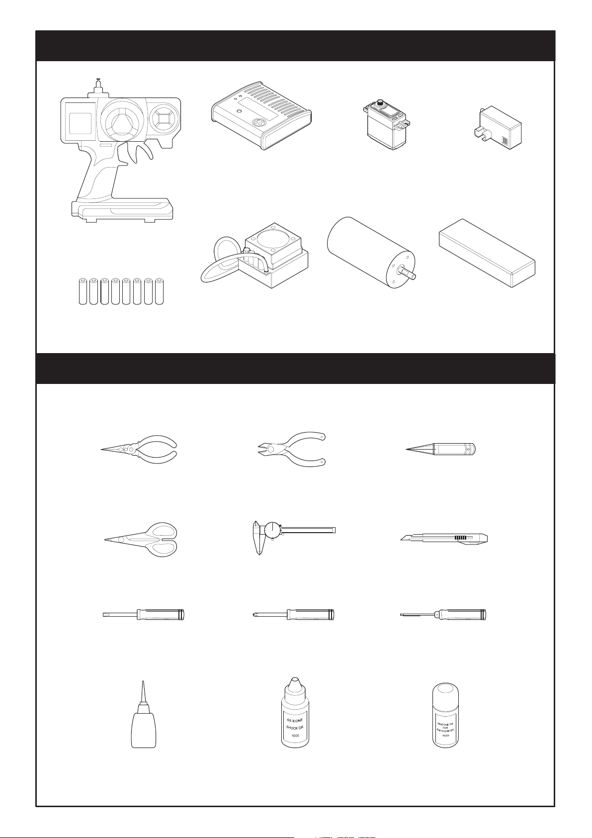
˙
Shock Oil
˙
Hex Wrench
(1.5,2.0,2.5,3.0mm)
˙
Screwdriver (+)
˙
Screwdriver (-)
˙
Body Scissors
˙Caliper
˙Knife
˙Cutting Pliers
˙Needlenose Pliers
˙Um-3 Battery (8 Pcs)
˙2 Channel Radio Set
EXTRA STUFF NEEDED
CAUTIONS
INTRODUCTION
(Included with RTR version)
(Purchase separately)
(Purchase separately)
˙Tyre Glue
˙
Differential Silicone oil
EXTRA STUFF NEEDED TO MAINTAIN YOUR BUGGY
ADDITIONAL ITEMS NEEDED FOR OPERATION
˙Body Reamer
˙
AC/DC Charger & Discharger
˙Steering Servo
˙Receiver
˙Li-Po Battery 2 Cell (7.4V) X2
Li-Po Battery 4 Cell (14.8V)
˙
Brushless Motor
˙ Brushless Speed Control
(Included with RTR version)
(Included with RTR version)
(Purchase separately)
(Included with RTR version)
(Included with RTR version)
(Purchase separately)
2
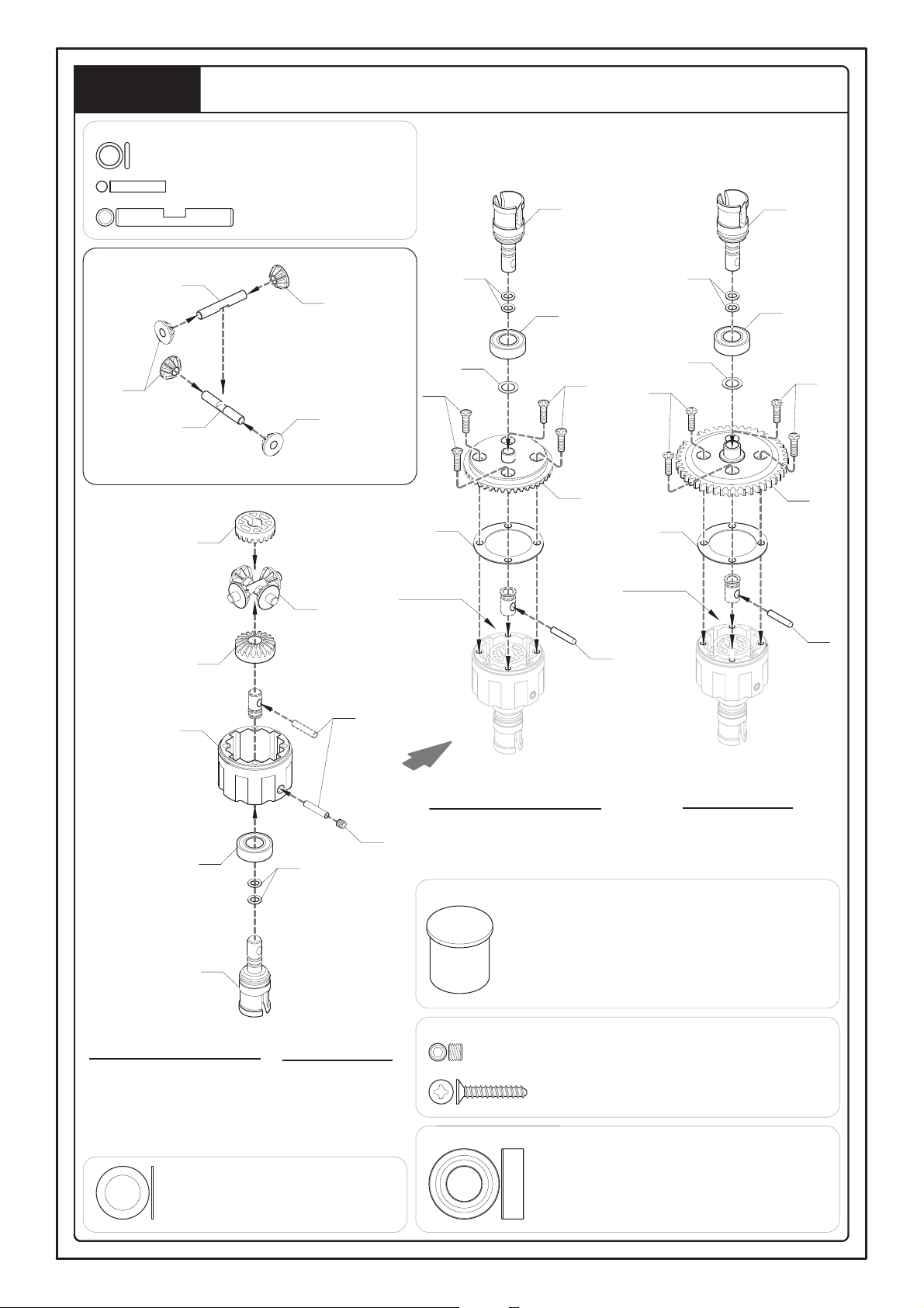
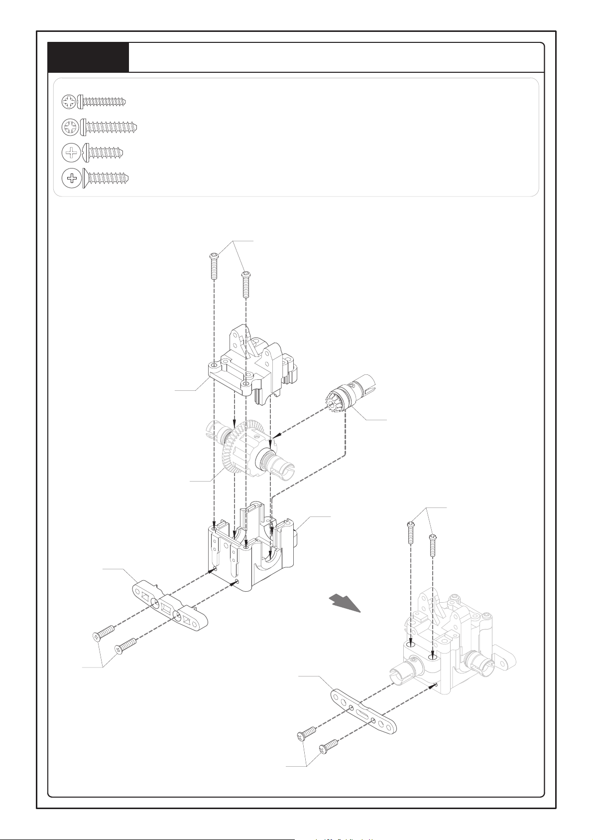
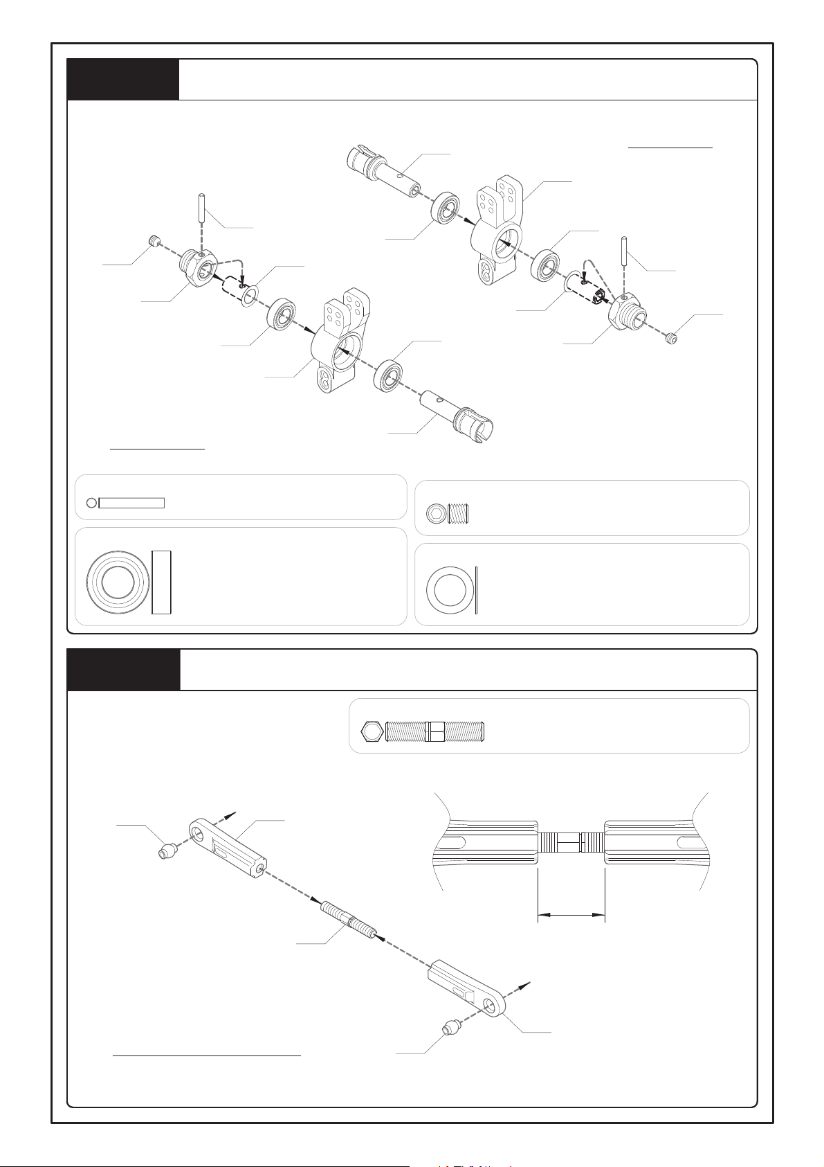
Step 1
Front, Rear and Center Differentials
1A - O-Ring 3x1mm -- 12
1B - Pin 2.5x12.8mm -- 6
1C - Pin 4x26.6mm -- 6
1C
MV22873
MV22873
1C
MV22873
<1-1>
MV22873
MV22873
Step 1-1
1B
1E
1G
MV22873
MV11721
For Center (x1)
For Front and Rear (x2)
For Front and Rear (x2)
For Center (x1)
Differential Oil -- 1
1E - Grub Screw 4x3mm -- 3
1F - F/H Tapping Screw 3x16mm -- 12
1G - Ball Bearing 8x16x5mm -- 6
1D - Shim 8x12x0.4mm -- 3
1B
Differential
Oil
MV22873
1F
1D
1A
MV11721
1G
1F
MV22811
(43T)
MV11721
1A
1G
1D
1F
1F
MV22832
(48T)
MV22873
Differential
Oil
1B
1A
3
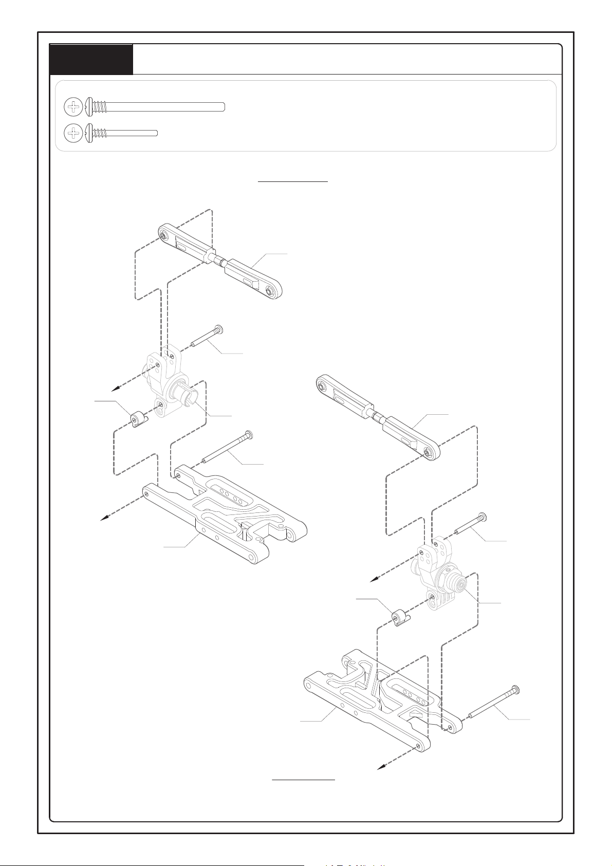
Step 2
Front Gearbox and Front Up Arm Carry Mounting
2B
For Front and Rear (x2)
2A
2C
MV1173
MV22821
13T
2D
2mm
<2-1>
2C- Shim 8x12x0.2mm -- 4
2A- Button Bearing 8x16x5mm -- 4
2B - Grub Screw w/Threadlock 5x4mm -- 2
2D- Shim 8.1x12x0.3mm -- 2
2E
2E - Round Head Tapping Screw 4x18mm -- 2
2H
MV162
Step 2-1
Step 1
MV162
MV162D2T
MV162D1
2F
2G
2H - Round Head Tapping Screw 3x15mm -- 2
2F - F/H Tapping Screw 4x16mm -- 2
2G - Button Head Tapping Scerw 4x8mm -- 2
4
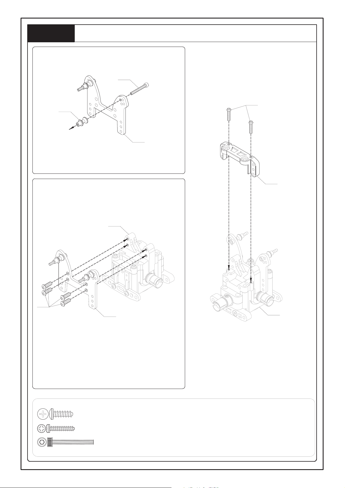
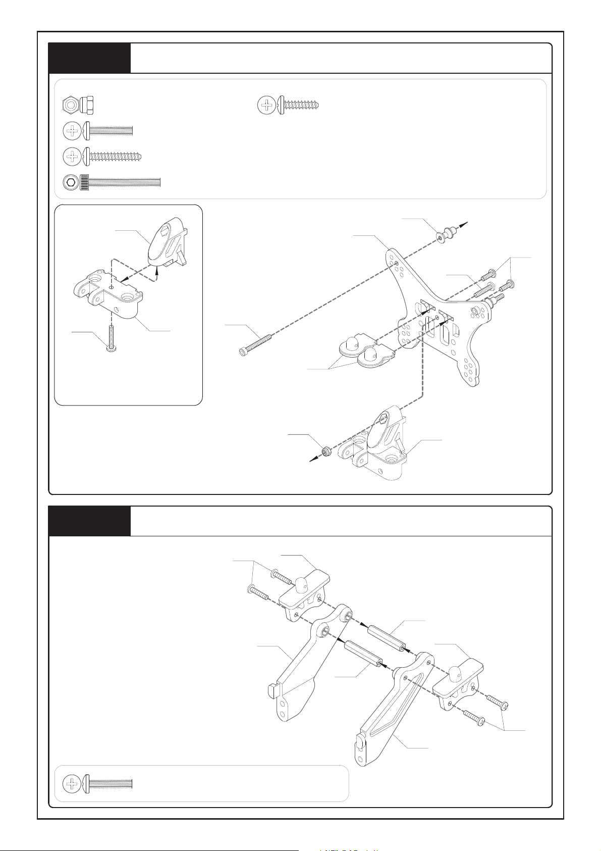
Front Shock Tower and Suspension Plate Holder Mounting
Step 3
3C
3B
MV110
MV1321T
<3-1>
MV162U1
Step 2
3A
Step 3-2
Step 3-1
<3-2>
3A - Button Head Tapping Screw 4x12mm -- 4
3B - Round Head Tapping Screw 3x15mm -- 2
3C - Cap Screw 3x25mm -- 2
5
Front Wheel Hubs
For Right and Left Sides (x2)
MV105
4C
XV134
4C
4D
4G
4A
MV107
<4-1>
4B
MV3531
4E
MV3481
(L)
Step 4-1
(R)
Step 4-1
(L)
MV3481
(R)
4F
MV3531
For Right Side
4B
For Left Side
4A - Grub Screw w/Threadlock 5x5mm -- 2
4B - Cap Screw w/Threadlock 4x12mm -- 4
4E - Shim 6.1x8x0.1mm -- 2
4C - Ball Bearing 8x16x5mm -- 4
4F - Shim 6.1x8x0.2mm -- 2
4G - Shim 8.1x12x0.3mm -- 2
4D - Pin 2.5x16.8mm -- 2
Step 4
6
Front Upper, Lower Suspension Arms
5A - Hub Stud 3x45.5mm -- 4
5B - Turnbuckle 5x25mm -- 2
MV349F1
10mm
5B
(MV34911)
MV349F1
For Right and Left Sides (x2)
<5-1>
For Left Side
Step 5-1
( L)
5A
(VX1502)
Step 5-1
(R)
5A
(VX1502)
Step 4
(R)
Step 4
( L)
MV347F1
(L)
MV347F1
(R)
For Right Side
Step 5
5A
(VX1502)
5A
(VX1502)
7
Front Suspension Arms
Step 3
Step 5
(R)
6B
(MV1112)
6A
(CB150)
Step 5
(L)
6A - Hub Stud 3x27mm -- 2
6B - Hub Stud 5x63mm -- 2
Step 6
MV3562
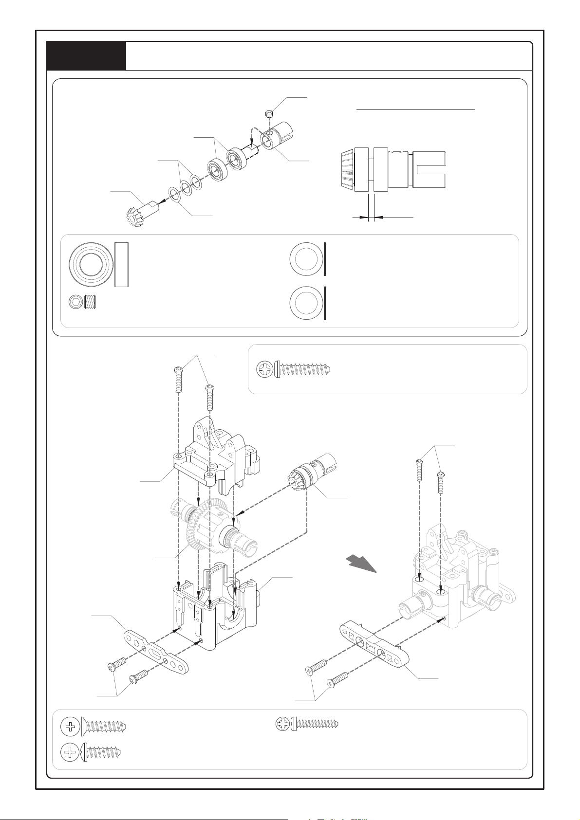
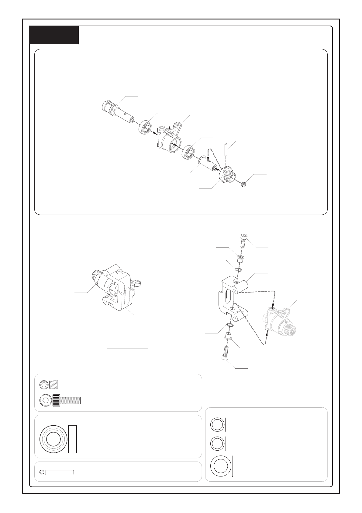
8
Rear Gearbox
7A - Round Head Tapping Screw 3x15mm -- 2
7B - Round Head Tapping Screw 4x18mm -- 2
7C - Button Head Tapping Scerw 4x8mm -- 2
7D - F/H Tapping Screw 4x16mm -- 2
7B
MV162
Step 1
MV162D1
7D
7C
MV162D3T
7A
Step 2-1
MV162
Step 7
9
Rear Shock Tower and Body Mount
8A - Lock Nut 3mm -- 1
8C - Button Head Machine Screw 3x15mm -- 1
8D - Button Head Tapping Screw 3x18mm -- 1
8E - Cap Screw 3x25mm -- 2
8B - Button Head Tapping Screw 3x12mm -- 2
MV1331T
MV110
8B
8E
MV142
8A
Step 8-1
MV162U3
MV162U2
8D
<8-1>
! Please assemble both right and left sides.
Spoiler Mount
9A - Button Head Machine Screw 3x15mm -- 4
MV141
(R)
9A
MV141
MV141
MV141
MV141
9A
MV141
(L)
Step 8
8C
Step 9
10
Rear Shock Tawer and Spoiler Mounting
10A - Button Head Tapping Screw 4x20mm -- 4
10B - Round Head Tapping Screw 3x15mm -- 2
10C - Round Head Tapping Screw 4x25mm -- 2
Step 9
10B
10C
10A
Step 8
Step 7
Step 10
11
XV1624R1
11A
(CB150A)
Rear Chassis Brace Mounting
11A - Hub Stud 3x22.5mm -- 1
Step 11
Step 10
12
Rear Hubs
Step 12
For Left Side
MV105
MV3461
(L)
12A
12B
12B
12C
12D
12A
MV107
12D
12C
12B
MV107
12B
MV3461
(R)
MV105
For Right Side
12A - Pin 2.5x16.8mm -- 2
12C - Grub Screw w/Threadlock 5x5mm -- 2
12B - Ball Bearing 8x16x5mm -- 4
12D - Washer 8x12x0.2mm -- 2
Step 13
Rear Upper Suspension Arms
13A - Turnbuckle 5x36mm -- 2
MV349R1
MV113
7mm
13A
(MV3492)
MV349R1
For Right and Left Sides (x2)
MV113
13
Rear Upper, Lower Suspension Arms and Hubs
Step 14
14A - Hub Stud 3x45.5mm -- 2
14B - Hub Stud 3x22.5mm -- 2
For Right Side
Step 13
(R)
14B
(CB150A)
MV3461
Step 12
(R)
Step 13
(L)
14A
(VX1502)
14B
(CB150A)
MV347R1
MV3461
Step 12
(L)
14A
(VX1502)
MV347R1
For Left Side
14

Rear Suspension Arms
Step 15
Step 11
15B
Step 14
(R)
15C
(MV1112)
Step 14
(L)
15A
MV3562
! Please assemble both
right and left sides.
15A - Lock Nut 3mm -- 2
15B - Cap Screw 3x18mm -- 2
15C - Hub Stud 5x63mm -- 2
15

Chassis
MV3073
16A
16A - F/H Machine Screw w/Threadlock 4x10mm -- 2
Step 16
MV3011T
16

Step 17
Side and Silencer Lever Mounting
MV3001
(R)
MV3001
(L)
17A
Step 16
17B
17B
17B
17C
17A - Flanged Lock 3mm -- 1
17B - F/H Tapping Screw 3x10mm -- 5
17C - F/H Machine Screw 3x10mm -- 1
17

Servo Saver
18A - Lock Nut 3mm -- 2
18D
18B - Servo Saver Screw 3x19.7mm -- 2
MV3073
18D
MV3071
18C - Shim 8x12x0.8mm -- 2
MV3071
MV3071
18D - Bushing 6x10x3mm -- 4
18D
18E - Flanged Ball Bearing 5x8x2.5mm -- 2
MV3073
MV3073
18D
<18-1>
18B
(MV3074)
MV3075T
18E
18C
Step 18-1
Step 18-1
18A
Step 18
18

19B
Step 19-1
(L)
Step 19-1
(R)
Step 18
19A
<19-1>
For Right and Left Sides (x2)
MV1301
(V221524)
MV1301
(MV113)
19C
(MV1301)
30.7mm
MV1301
(MV1131)
MV1301
(V221524)
19C - Turnbuckle 5x48mm -- 2
19B - Cap Screw 3x18mm -- 2
19A - Lock Nut 3mm -- 2
Steering Rod
Step 19
19

Step 20
Shock Bodies and Shock Shafts
20E - Shock Shaft 3.5x52mm -- 2
20A - Lock Nut 2.6mm -- 4
20F - Shock Shaft 3.5x61mm -- 2
20B - Washer 2.5x5.9x0.5mm -- 4
20G - Shock Body 14x45mm -- 2
20C - O-Ring 2.5x1mm -- 4
20D - O-Ring 3.5mm -- 8
20H - Shock Body 14x53mm -- 2
20I - Shock Body 14x53mm -- 4
For Front (x2)
33A3520
20C
20A
Please Lock Here
20B
Step 20-1
20E
(33A3520)
20A
20B
MV138017
20G
(33C450TA)
32A3520
20D
32A3610
Please Lock Here
20C
33C450TA
Step 20-1
20F
(32A3610)
MV138017
20H
(33C530TA)
32A3610
20D
33C530TA
For Rear (x2)
33C450TA
33C530TA
20I
<20-1>
20

Shock Oil
33C450TA
33C530TA
Silicone Shock Oil
(Not Included)
! After filling with shock oil,
GENTLY pump shock shaft
up and down several times
to eliminate air bubbles.
33C450TA
33C530TA
Step 20
For Front and Rear (x4)
Shock Springs
Step 21
(Front)
For Front (x2)
MV138017
Step 21
(Rear)
MV112
22A
(3106315BA)
MV138017
MV112
22B
(3108315BA)
For Rear (x2)
22A - Front Shock Spring 63x1.5mm -- 2
22B - Rear Shock Spring 83.5x1.5mm -- 2
Step 21
Step 22
21

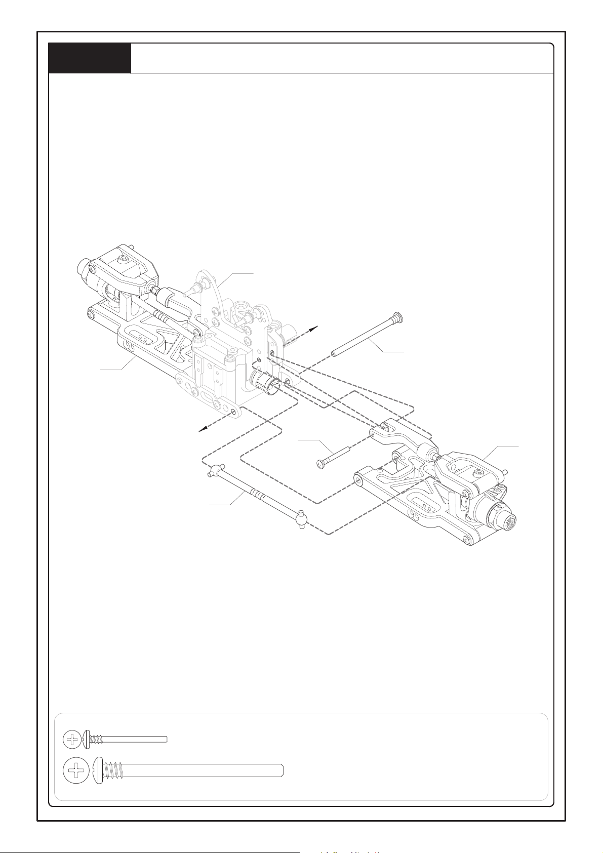
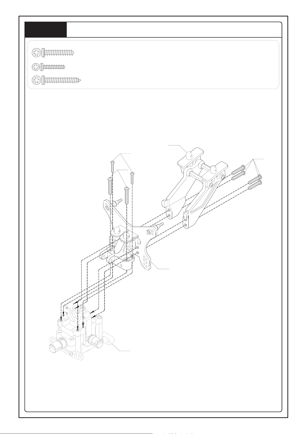
Front and Rear Shock Mounting
Step 6
Step 22
MV1382
23A
Step 22
(34C098A03)
23B
For Front
Step 22
Step 15
MV1382
23A
Step 22
(34C115A03)
23B
For Rear
23A - Flanged Lock Nut 3mm -- 4
23B - F/H Machine Screw 3x20mm -- 4
Step 23
22

24A
24B
Step 17
MV1401
Step 23
24B - F/H Tapping Screw 4x16mm -- 4
24A - F/H Tapping Screw 3x10mm -- 2
Front Bumper, Suspension Mounting
Step 24
23

25C - F/H Tapping Screw 4x16mm -- 4
25A - F/H Machine Screw 3x25mm -- 1
25B - Flange Lock Nut 3mm -- 1
25A
25C
25C
Step 24
25B
Step 23
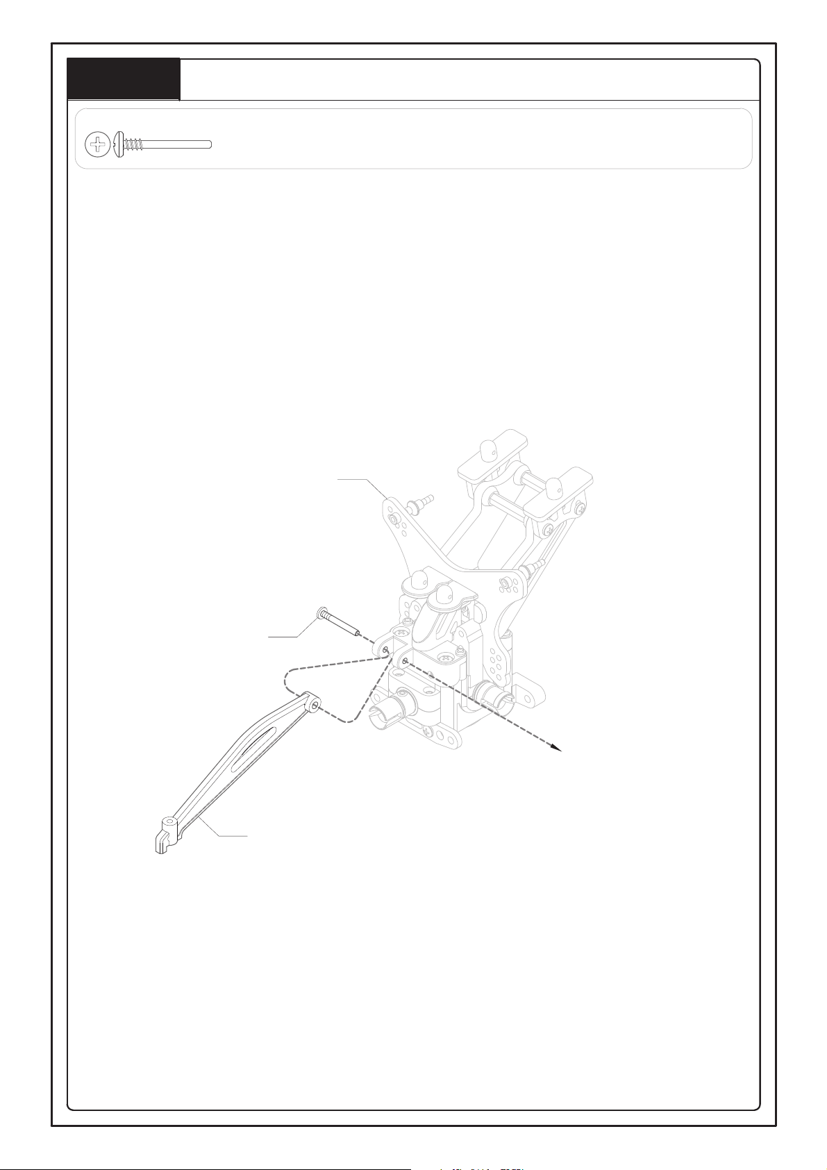
Rear Suspension Mounting
Step 25
24

26A - Cap Screw w/Threadlock 3x18mm -- 2
Step 25
Step 19
26A
26A
Steering Linkages Mounting
Step 26
25

27A - Round Head Tapping Screw 4x25mm -- 2
27C - Washer-Head Screw W/Threadlock 4x10mm -- 2
27D - Shim 6.1x9.8x0.2mm -- 2
MV142
MV3076T
27B
27B - Button Head Tapping Screw 3x12mm -- 1
Front Body Pillar
Step 27
27A
27C
Step 27-1
27C
27D
<27-1>
Step 26
26

Step 28
Servo Mounting
28A - F/H Machine Screw w/Threadlock 3x8mm -- 3
28B - Button Head Machine Screw 3x8mm -- 3
28C - Button Head Tapping Screw 3x10mm -- 4
28B
Step 28-2
MV308
MV308
Step 27
<28-1>
28C
CH1
(Steering Servo)
Step 28-1
28A
28A
MV310
<28-2>
27
MV30211AL

Motor Mounting and Center Differential
Step 29
29D
EL36741CO
29B
<29-1>
29B
29A
MV3042T
MV3041
Step 1
(Center)
MV3041
<29-2>
29A - Button Head Tapping Screw 3x15mm -- 2
29B - Button Head Machine Screw w/Threadlock 3x12mm -- 3
29C - Button Head Machine Screw w/Threadlock 3x6mm -- 1
29D - Grub Screw w/Threadlock 4x4mm -- 1
<29-3>
29C
Double Side Tape
(Move Out)
EV30421
Electronic
Speed
Control
28
EV0141
EV3041

Electric Speed Control Mounting
Step 30
Step 29-1
Step 29-2
Step 29-3
30A
30A - F/H Tapping Screw 3x8mm -- 2
29

Centre Differential and Drive Shafts
MV3551
31A
Step 28
Step 30
31A - F/H Tapping Screw 4x16mm -- 2
Step 31
31B
MV3562
! ESC and Motor Install Diagram
<31-1>
Brushless Motor
Electronic Speed Control
Blue
Yellow
Orange
C
B
A
Black
Rad
Yellow
31B - F/H Machine Screw w/Threadlock 4x10mm -- 2
30

31
32A - F/H Machine Screw w/Theadlock 3x8mm -- 16
32A
32A
32A
Step 31
Step 32-1
Step 32-1
<32-1>
32A
32A
32A
EV3021AL
EV3021AL
32A
32A
32A
Battery Box
Step 32
32B - SD Post 6x12mm --10
32B
32B
32B
32B
32B
32B
32B

Receiver case
Step 33
MV3746
MV3746
XV3742
33E
<33-1>
Step 33-1
33A
Receiver
33B
Step 32
33B
33C
XV3742
33D
(XV3742)
33A- Button Head Tapping Screw 3x10mm -- 4
33E- Flanged Lock Nut 4mm -- 1
33B- Button Head Machine Screw 3x15mm -- 2
33C- F/H Machine Screw w/Theadlock 3x8mm -- 2
33D- Post 6x19mm -- 2
32

Steering Linkage Mounting
34C - Button Head Machine Screw 3x12mm -- 1
34A - Lock Nut 3mm -- 2
34D - Button Head Machine Screw 3x18mm -- 1
34B - Grub Screw 3x16mm -- 1
34A
Servo Arm
(Included with Servo)
MV1302
MV1302
34B
34C
MV1302
<34-1>
MV1302
Retaining Screw
(Included with Servo)
34D
Step 34-1
Step 33
34A
Step 34
33

Battery
Step 34
Step 35
Li-Po Battery
(2 Cell)
Z477/1
34

EV3021AL
EV3021AL
EV3021AL
Electric Speed Control
Battery 14.8V
Li-Po Battery
4-Cells(14.8V)
Li-Po Battery
2-Cells(7.4V)
NEG-
POS+
Brushless Motor
ELS13
NEG-
NEG-
POS+
NEG-
Battery 11.1V
Li-Po Battery
2-Cells(7.4V)
POS+
POS+
Li-Po Battery
3-Cells(11.1V)
Red (Positive)
White (Neutral)
Black (Negative)
Brushless ESC
CH2
CH. 1
CH. 2
CH. 3
BATT
Receiver
For Fan(6V)
Battery 14.8V
Switch
(On/Off)
Li-Po Battery
2-Cells(7.4V)
Steering Servo
CH1
Li-Po Battery
2-Cells(7.4V)
Step 36
35

MV37001BA
MV3692S
MV3692S
Wheels and Tires
For Right and Left Sides (X4)
<52-1>
! Use small amount instant
cement into the groove of the
wheel. Make sure the tire is
secure on the wheel.
! Please glue both sides.
Instant Cement
(Not Included)
! Apply instant cement into
the groove of the wheel.
For Right and Left Sides (x4)
Step 38
! DO NOT cut the excess antenna shorter.
Allow the excess antenna wire to hang out
beyond the end of antenna support tube.
! Slide the antenna through the antenna
support tube, then push the antenna
support tube into the antenna mount.
Antenna Support Tube
Receiver
! Proper pruning the antenna support
tube does not exceed the body.
Suggested length: 50mm
Antenna Support Tube Mounting
Step 37
36

Wheels,Body and Wing Mounting
39A - Wheel Nut 17mm -- 4
MV1201
39A
(MV106)
XV3753BA
Step 35
Step 38
Step 38
39A
(MV106)
Step 39
XV1204
MV120
BODY
37

1/8 REX EP REPLACEMENT SPARE PARTS LIST
BB0306025
BB0508025T
BB051004
BB050825
Ball Bearings 3x6x2.5mm
Ball Bearing 5x10x4mm
Ball Bearing 5x8x2.5mm
Ball Bearings - Flanged 5x8x2.5mm
BU061003
BB081605
EV0141
EV3021AL
Ball Bearing 8x16x5mm
Motor Pinion Gear 14T - Steel
Battery Holder
Bushings 6x10x3mm
L=22.5mm
L=22.5mm
EV30421AL
EV3041
V221524
V221523
ESC Suspension Plate - Aluminium
Motor Mount
Ball Ends - 4mm For 7mm Ball
Ball Ends - 4mm For 7mm Ball
MV107
L=14.2mm
MV112
MV106
MV110
Wheel Nuts
Hex Hubs 17mm
Shock Mounting Studs
Balls - Steel 6.9x4.9mm
L=10mm
L=36mm
MV1131
MV1173
L=21mm
MV11721
MV113
Pinion Output Joint 21mm
Differential Output Joint 36mm
7x3mm Ball With Flange
Balls - Steel 7x3mm
L=43mm
MV1302
MV1301
L=48mm
L=45mm
MV105
33C450TA
Steering Rod Set
Steering Servo Rod Set
Wheel Shaft
Shock Body Set - C Type Titanium
38

32A3520
33C530TA
MV138017
Shock Body Set - C Type Titanium
Shock Rebuild Kit - C Type
Shock Shaft - C Type 3.5mm
MV1401
34C098A03
L=130.5mm
L=109mm
L=61mm
32A3610
34C115A03
Shock Set Titanium W/Black Spring
- C Type
Shock Set Titanium W/Black Spring
- C Type
Bumper
Shock Shaft - C Type 3.5mm
MV134
3106315BA
3108315BA
L=83.5mm
L=63mm
MV1112
L=63mm
Wheel Hub Front
Shock Springs 1.5mm - Black
Shock Springs 1.5mm - Black
Hub Stud - 5mm
CB150
MV150A
L=45.5mm
L=27mm
L=22.5mm
MV162
VX1502
Hub Stud Rear - 3mm
Hub Stud Rear - 3mm
Arm Stud Front - 3mm
Gear Box Halves - Front & Rear
MV162U1
MV162D3T
MV162D2T
MV162D1
Front Suspension Plate - Alu
Upper Arm Carry Front
Rear Suspension Plate - Alu
Suspension Plate Holder Set 0-3Deg
MV1321T
MV1331T
MV162U3
MV162U2
Shock Tower Rear 3mm - Alu
Brace Mount For Gear Box
Brace Mount For Rear Shock Tower
Shock Tower Front 3mm - Alu
L=53mm
L=52mm
MV1382
Shock Spring Adjust
39

Servo Mount Set - Throttle
Rear Hubs - Left/Right
Rear Suspension Arms - Lower
Front Suspension Arms - Lower
MV310
MV3461
MV347R1
MV347F1
Servo Saver Screw Set
Servo Saver Steering Plate 3mm - Alu
Servo Saver Plate 2mm - Alu
Fuel Tank Post
MV3074
MV308
MV3075T
MV3076T
Centre Differential Mount
Brake Plate - Alu
Servo Saver Plastic Parts
Servo Saver Metal Parts
MV3073
MV3071
MV3041
MV3042T
Side Guard
Front/Rear Differential 43T - Assembly
Chassis 3mm 6061 - Alu
MV3011T
MV22873FR1
MV3001
Differential Set - Bevel Gears
Spur Gear - 48T
Ring Gear - 43T
Pinion Gear -13T
MV22873
MV22821
MV22832
MV22811
Body support For Buggy
Wing Mount
Gaskets for Bevel Differentials
MV142
MV141
MV227542
MV22873M481
Centre Differential 48T - Assembly
40
Main Gear Plate
2mm Aluminum Color
MV30211AL

41
Receiver Mounting Box
XV3742
Body Clips Type "R"
Body Clips Type "R"
Tool Set
Body Clips Type "R"
L=27mm
L=65mm
MV1201
MV120
XV1204
SE285
L=80mm
Antenna Mount
Bi-Level Wing - Black
Buggy Tires
Racing Wheels - Black
MV37001BA
MV375BA
MV3746
MV3692S
Rear Suspension Arms - Upper
Rear Dog Bones - Centre
Rear Dog Bones - Axles
Rocker Pin
MV349R1
MV3531
MV3562
MV3551
L=93mm
L=97.8mm
Front Suspension Arms - Upper
Hubs Carrier Left/Right
Turnbuckles 5mm - Upper
Chassis Brace - Rear
L=25mm
MV3481
XV1624R1
MV34911
MV349F1
ELS193
EC5 Type "Y" Connector
EL36741CO
2370KV
Brushless Motor
EL66709CO
Brushless Speed Control
80A

1/8 REX EP OPTION PARTS LIST
EL00742
EL00711
EL0074
EL00745
Cooling Fan Mounting
Cooling Fan Y - Adapter
Cooling Fan - 30x30x10mm
Motor Heat - Sink
MV22812
L=56.2mm
MV138011
MV22822
EL00711F
Pinion Gear 13T - Steel
Motor Heat - Sink With Cooling Fans
Shock Shaft Set - Front 3.5mm
Ring Gear 43T - Steel
MV1383R13
Shock Spring Front 1.3mm - Red
MV1383W15
Shock Spring Front 1.5mm - White
MV1383Y
Shock Spring Front 1.6mm - Yellow
MV138014BA
MV1383BA
MV138016
L=58mm
L=47mm
MV1383B14
Front Shock Springs 1.7mm - Silver
Shock Rebuild Kit
Shock Body Set - Alu
Shock Spring Front 1.4mm - Blue
MV138B1Y16
MV1387B
Blue Body,Yellow Springs
Shock Bump Stops - Blue
MV138TA1Y16
Color Titanium,Yellow Springs
L=111mm
MV138B1W15
MV1387
Shock Absorber Front - Blue
Body,White Springs
Shock Bump Stops - Yellow
MV1393BA
Rear Shock Spring 1.7mm - Black
MV1393R13
Rear Shock Spring 1.3mm - Red
MV1393Y
Rear Shock Spring 1.6mm - Yellow
L=80.5mm
MV139014BA
MV139011
L=61mm
MV1393B14
Alu Steering Hub - Blue
Rear Shock Body Set - Alu
Shock Shaft Set - Rear 3.5mm
MV139B1Y16
Blue Body,Yellow Springs
MV139TA1Y16
Color Titanium,Yellow Springs
L=58mm
L=108mm
MV139B1W15
SEM138301
L=126mm
SEM13801BAY
Shock Absorber Rear - Blue Body,
White Springs
Front Shock Springs
1.4&1.5&1.6&1.7mm
Shock Absorber w/o Springs - Black
42

Silicone Differential Oil - 50K Wt
Silicone Shock Oil - 2000Wt
Silicone Differential Oil - 30K Wt
Silicone Differential Oil - 10K Wt
SEG050
SE112
SEG030
SEG010
Silicone Switch Cover - Red % Yellow
Silicone Shock Oil - 1000Wt
Silicone Shock Oil - 40Wt
SE111
SE030
SE110
Foam Tires w/Wheels - Yellow
MV386Y
Foam Tires w/Wheels - White
MV386W
Foam Tires w/Wheels - Black
Foam Tires w/Wheels - Black
MV386BA
MV3862BA
Foam Tires w/Wheels - Yellow
Foam Tires w/Wheels - Yellow
MV3862Y
MV3861Y
Foam Tires w/Wheels - White
Foam Tires w/Wheels - White
MV3862W
MV3861W
Foam Tires w/Wheels - Black
Racing Wheels - Black
MV3861BA
MV37003BA
Racing Wheels - Yellow
MV37003Y
Racing Wheels - Yellow
Racing Wheels - White
MV37003W
MV37002Y
Racing Wheels - White
Racing Wheels - Silver
MV37003GA
MV37002W
CVD Universal Joint Rebuild Kit
Racing Wheels - Silver
CVD Universals
Tire Racing
MV3574
L=123mm
MV3571
MV37002GA
MV0931
Dust Boots - Shock Shaft
Ball End Mount
Shock Absorber w/o Springs - Black
Front Shock Springs
1.4&1.5&1.6&1.7mm
SEM1591
L=80.5mm
MV1385
SEM13901BAY
L=125mm
SEM139301
43

Alu Servo Saver w/Bearings - Blue
Alu Servo Saver - Blue
Brake Disk Orientation
Alu Differential Housing
SEM3072B
SEM3043
SEM3071B
SEM2288
Titanium Turnbuckle - Upper Front
Titanium Turnbuckle - Upper Rear
Titanium Turnbuckles (Tie-Rods) 4mm
Alu Differential Case
SEM3492
SEM130
L=48mm
SEM3491
L=36mm
L=25mm
SEM2287
Ball Ends - 3.5mm for 7mm Ball
Rear Suspension Plate - Blue
Ball Ends - 3.5mm for 7mm Ball
Front Steering Hubs - Blue
SEM162D3B
MV1592
MV1591
L=25.5mm
L=22.5mm
SEM1341B
Front Suspension Plate - Blue
Suspension Plate Holder 30 - Alu
Suspension Plate Holder 20 - Alu
Front Aluminum Brace 7075 - Blue
SEM162C3
SEM162C2
SEM1621FB
SEM162D2B
Rear Shock Tower 5mm 7075 - Blue
Front Shock Tower 5mm 7075 - Blue
Rear Chassis Brace - Blue
Front Shock Tower 4mm
- Carbon Fiber
SEM1621B
SEM1321B
SEM1335B
SEM1325B
Silicone Differential Oil - 70K Wt
CVD Dust Boots - Blue
Silicone Differential Oil - 100K Wt
Silicone Differential Oil - 200K Wt
SEG070
SEM1170B
SEG100
SEG200
44

SEM3011BA1
SEM3461B
SEM3076B
SEM3481B
Alu Rear Hub L/R - Blue
Chassis 3mm 7075 - Black
Servo Saver Plate - Blue
Alu Hub Carrier L/R - Blue
SEM15914R
SEM15911
SEM15914L
SEM159135R
Ball End Cover
Steel Ball End "L" - M4x0.7mm
Steel Ball End "R" - M4x0.7mm
Steel Ball End - M3.5x0.6mm
SEM3571
EV0121
SEM375T
SEM1412T
Axle Adapters - Universals
Alu Super Wing
Motor Pinion Gear 12T - Steel
Alu Wing Mount
XV3751RE
SEM106BA
Bi-Level Wing - Red Type "S"
Wheel Nuts w/Nylon Lock - Black
SEM106TA
XV3751W
Wheel Nuts w/Nylon Lock - Titanium
Bi-Level Wing - White Type "S"
XV3751Y
SEM106S
Bi-Level Wing - Yellow Type "S"
Wheel Nuts w/Nylon Lock - Silver
XV3751BA
SEM106B
Bi-Level Wing - Black Type "S"
Wheel Nuts w/Nylon Lock - Blue
SE93010G
Micro Corner Markers - Green
SE93010O
Micro Corner Markers - Orange
SE93010R
Micro Corner Markers - Red
SE93010Y
SE93020R
SR100
Battery Level Indicator
Micro Corner Markers - Yellow
Racing Cones For Micros - Red
45
 Loading...