

Page 1

1:10 EP Buggy „Ranger“ 4WD
(Bausatz)
1:10 EP Buggy „Ranger“ 4WD
(Construction Kit)
1:10 EP Buggy „Ranger“ 4WD
(kit d’assemblage)
1:10 EP Buggy „Ranger“ 4WD
(bouwset)
Best.-Nr. / Item No. / N° de commande / Bestnr.: 23 67 16
Bedienungsanleitung Seite 2 - 39
Operating Instructions Page 40 - 77
Notice d’emploi Page 78 - 115
Gebruiksaanwijzing Pagina 116 - 153
¨
¨
Version 05/09
Page 2

1. Einführung .......................................................................................................................................................... 3
2. Bestimmungsgemäße Verwendung .................................................................................................................. 4
3. Lieferumfang ...................................................................................................................................................... 4
4. Symbol-Erklärung .............................................................................................................................................. 4
5. Sicherheitshinweise ........................................................................................................................................... 5
6. Batterie- und Akku-Hinweise ............................................................................................................................. 8
7. Zusammenbau ................................................................................................................................................... 9
8. Fahrwerk einstellen ..........................................................................................................................................27
9. Akkupack aufladen .......................................................................................................................................... 31
10. Inbetriebnahme ................................................................................................................................................ 32
Inhaltsverzeichnis
a) Allgemein ..................................................................................................................................................... 5
b) Zusammenbau ............................................................................................................................................. 5
c) Betrieb .......................................................................................................................................................... 6
a) Vorderes Differenzial ................................................................................................................................... 9
b) Hinteres Differenzial .................................................................................................................................. 11
c) Querlenker vorn ......................................................................................................................................... 14
d) Querenker hinten ....................................................................................................................................... 15
e) Motorhalter und Motor ............................................................................................................................... 16
f) Differentiale am Chassis montieren .......................................................................................................... 17
g) Lenkung ..................................................................................................................................................... 18
h) Vorderachse: Dämpferbrücke, Querlenker, Stoßdämpfer ........................................................................ 20
i) Hinterachse: Dämpferbrücke, Querlenker, Stoßdämpfer ..........................................................................21
j) Lenkservo .................................................................................................................................................. 22
k) Getriebeabdeckung, Chassisbrücke ......................................................................................................... 23
l) Akkuhalterung ............................................................................................................................................ 24
m) Heckspoiler-Halterung ............................................................................................................................... 24
n) Vordere Karosseriehalterung ..................................................................................................................... 25
o) Radmitnehmer und Räder ......................................................................................................................... 25
p) Empfänger und Fahrtregler ....................................................................................................................... 26
a) Einstellung des Radsturzes ....................................................................................................................... 27
b) Einstellung der Spur .................................................................................................................................. 28
c) Vorderachse ............................................................................................................................................... 29
d) Hinterachse ................................................................................................................................................ 30
a) Abnehmen der Karosserie ......................................................................................................................... 32
b) Akkupack in das Fahrzeug einsetzen ....................................................................................................... 32
c) Akkus/Batterien in die Fernsteuerung (Sender) einlegen ......................................................................... 32
d) Fernsteuerung (Sender) einschalten ......................................................................................................... 32
e) Akkupack am Fahrtregler anschließen ...................................................................................................... 32
f) Fahrtregler einschalten .............................................................................................................................. 33
Seite
2
Page 3

Seite
g) Antriebs- und Lenkfunktionen prüfen ........................................................................................................ 33
h) Karosserie aufsetzen und befestigen ........................................................................................................ 33
i) Fahrt beenden ........................................................................................................................................... 34
j) Tragen des Fahrzeugs ............................................................................................................................... 34
11. Reinigung und Wartung ................................................................................................................................... 35
a) Allgemein ................................................................................................................................................... 35
b) Einstellen des Zahnflankenspiels .............................................................................................................. 36
c) Quarzwechsel ............................................................................................................................................ 36
12. Entsorgung .......................................................................................................................................................37
a) Allgemein ................................................................................................................................................... 37
b) Batterien und Akkus ................................................................................................................................... 37
13. Behebung von Störungen ................................................................................................................................ 38
14. Technische Daten ............................................................................................................................................ 39
1. Einführung
Sehr geehrte Kundin, sehr geehrter Kunde,
wir bedanken uns für den Kauf dieses Produkts.
Dieses Produkt erfüllt die gesetzlichen, nationalen und europäischen Anforderungen.
Diese Bedienungsanleitung gehört zu diesem Produkt. Sie enthält wichtige Hinweise zur Inbetriebnahme und Handhabung. Achten Sie hierauf, auch wenn Sie dieses Produkt an Dritte weitergeben.
Heben Sie deshalb diese Bedienungsanleitung zum Nachlesen auf!
Alle enthaltenen Firmennamen und Produktbezeichnungen sind Warenzeichen der jeweiligen Inhaber. Alle Rechte
vorbehalten.
Bei technischen Fragen wenden Sie sich bitte an:
Tel.: 0180/5 31 21 11
Fax: 0180/5 31 21 10
E-Mail: Bitte verwenden Sie unser Formular im Internet: www.conrad.de, unter der Rubrik „Kontakt“.
Mo. bis Fr. 8.00-18.00 Uhr
www.conrad.at
www.business.conrad.at
Tel.: 0848/80 12 88
Fax: 0848/80 12 89
E-Mail: support@conrad.ch
Mo. bis Fr. 8.00-12.00, 13.00-17.00 Uhr
3
Page 4

2. Bestimmungsgemäße Verwendung
Bei diesem Produkt handelt es sich um den Bausatz eines allradangetriebenen Modellfahrzeugs.
Zum Betrieb erforderliche Zubehörteile (nicht im Lieferumfang): Fernsteueranlage (Sender/Empfänger), Lenkservo,
Fahrtregler, Fahrakku (Racingpack), Batterien/Akkus für die Fernsteueranlage, Ladegerät.
Das Produkt ist kein Spielzeug, es ist nicht für Kinder unter 14 Jahren geeignet.
Beachten Sie alle Sicherheitshinweise dieser Bedienungsanleitung. Diese enthalten wichtige Informationen zum Umgang mit dem Produkt.
Die Informationen dieser Anleitung beziehen sich zum Teil auf den Bausatz, zum Teil auch auf das
zusammengebaute Fahrzeug, das mit zusätzlichen Baugruppen (Sender/Empfänger, Fahrtregler,
Lenkservo, Fahrakku, jeweils nicht im Lieferumfang!) fahrfertig gemacht wird.
3. Lieferumfang
• Fahrzeug-Bausatz
• Elektromotor Typ 540
• Bedienungsanleitung
Die Ersatzteilliste zu diesem Produkt finden Sie auf unserer Website www.conrad.com im DownloadBereich zum jeweiligen Produkt.
Alternativ können Sie die Ersatzteilliste telefonisch anfordern, die Kontaktdaten finden Sie am Anfang
dieser Bedienungsanleitung im Kapitel „Einführung“.
4. Symbol-Erklärung
Das Symbol mit dem Ausrufezeichen weist Sie auf besondere Gefahren bei Handhabung, Betrieb oder
Bedienung hin.
Das „Pfeil“-Symbol steht für spezielle Tipps und Bedienhinweise.
4
Page 5

5. Sicherheitshinweise
Bei Schäden, die durch Nichtbeachtung dieser Bedienungsanleitung verursacht werden, erlischt
die Gewährleistung/Garantie. Für Folgeschäden übernehmen wir keine Haftung!
Bei Sach- oder Personenschäden, die durch unsachgemäße Handhabung oder Nichtbeachten
der Sicherheitshinweise verursacht werden, übernehmen wir keine Haftung! In solchen Fällen
erlischt die Gewährleistung/Garantie.
Von der Gewährleistung/Garantie ausgeschlossen sind ferner normaler Verschleiß bei Betrieb
(z.B. abgefahrene Reifen) und Unfallschäden (z.B. gebrochene Querlenker, zerkratzte bzw. zerstörte Karosserie usw.).
Sehr geehrte Kundin, sehr geehrter Kunde, diese Sicherheitshinweise dienen nicht nur zum Schutz des
Produkts, sondern auch zu Ihrer eigenen Sicherheit und der anderer Personen. Lesen Sie sich deshalb
dieses Kapitel sehr aufmerksam durch, bevor Sie das Produkt in Betrieb nehmen!
a) Allgemein
Achtung, wichtiger Hinweis!
Beim Betrieb des Modells kann es zu Sach- und/oder Personenschäden kommen. Achten Sie deshalb
unbedingt darauf, dass Sie für den Betrieb des Modells ausreichend versichert sind, z.B. über eine Haftpflichtversicherung. Falls Sie bereits eine Haftpflichtversicherung besitzen, so informieren Sie sich vor
Inbetriebnahme des Modells bei Ihrer Versicherung, ob der Betrieb des Modells mitversichert ist.
• Aus Sicherheits- und Zulassungsgründen (CE) ist das eigenmächtige Umbauen und/oder Verändern des Produkts
nicht gestattet.
• Das Produkt ist kein Spielzeug, es ist nicht für Kinder unter 14 Jahren geeignet.
• Das Produkt darf nicht feucht oder nass werden.
• Lassen Sie das Verpackungsmaterial nicht achtlos liegen, dieses könnte für Kinder zu einem gefährlichen Spiel-
zeug werden.
• Sollten sich Fragen ergeben, die nicht mit Hilfe der Bedienungsanleitung abgeklärt werden können, so setzen Sie
sich bitte mit uns (Kontaktinformationen siehe Kapitel 1) oder einem anderen Fachmann in Verbindung.
Die Bedienung und der Betrieb von ferngesteuerten Modellfahrzeugen muss erlernt werden! Wenn Sie
noch nie ein solches Fahrzeug gesteuert haben, so fahren Sie besonders vorsichtig und machen Sie sich
erst mit den Reaktionen des Fahrzeugs auf die Fernsteuerbefehle vertraut. Haben Sie Geduld!
b) Zusammenbau
• Beim Aufbau des Fahrzeugs besteht durch scharfe Kanten, spitze Teile und dem unsachgemäßen Umgang mit
Werkzeug Verletzungsgefahr.
• Bei falschem Zusammenbau kann es zur Beschädigung von Fahrzeugteilen und später zu schlechter Fahrleistung
kommen. Gehen Sie deshalb beim Zusammenbau gewissenhaft vor.
5
Page 6

• Bauen Sie das Fahrzeug nur auf einer ausreichend großen, ebenen, stabilen Fläche zusammen, schützen Sie die
Oberfläche z.B. eines Arbeitstisches mit einer geeigneten dicken Unterlage vor Kratzern.
• Wenden Sie beim Zusammenbau von Teilen keine Gewalt an; überdrehen Sie Schrauben nicht! Achten Sie jedoch
darauf, dass Schrauben, Muttern usw. korrekt fixiert sind.
• Verwenden Sie zum Zusammenbau geeignetes, einwandfreies Werkzeug.
• Nehmen Sie sich Zeit!
• Wenn Sie noch nie ein solches Fahrzeug zusammengebaut haben, so lassen Sie sich z.B. von einem Modellbaukollegen helfen, der mehr Kenntnisse hat. Gerade am Beginn einer „Modellbau-Karriere“ können einige wenige
gute Tipps und Hilfestellungen eines Profis viele Probleme leicht beseitigen.
c) Betrieb
• Stellen Sie vor jeder Inbetriebnahme sicher, dass innerhalb der Reichweite einer Fernsteuerung keine weiteren
Modelle auf der gleichen Frequenz betrieben werden. Die Kontrolle über die ferngesteuerten Modelle geht verloren!
Verwenden Sie immer unterschiedliche Frequenzen für jedes Modell.
• Bei jeder Inbetriebnahme müssen die Einstellungen der Trimmung für Vorwärts-/Rückwärtsfahrt sowie der Lenkung
kontrolliert und ggf. verändert werden.
Aus diesem Grund dürfen die Räder des Fahrzeugs bei Inbetriebnahme (Einschalten der Fernsteuerung und des
Fahrzeugs) noch nicht auf den Boden gestellt werden; stellen Sie das Fahrzeug auf eine geeignete Unterlage, so
dass sich die Räder frei drehen können (nicht in den Antrieb fassen!).
Stellen Sie dann die Trimmung entsprechend ein, so dass sich beim vollständigen Loslassen des Hebels für Vorwärts-/Rückwärtsfahrt (Neutralstellung) der Motor nicht mehr dreht bzw. die Lenkung gerade steht (eine genaue
Einstellung für Geradeausfahrt kann später während der Fahrt erfolgen).
• Schalten Sie bei der Inbetriebnahme immer zuerst die Fernsteuerung (Sender) ein. Erst danach darf der Akkupack
des Fahrzeugs mit dem Fahrtregler/Empfänger verbunden und das Modell eingeschaltet werden. Andernfalls kann
es zu unvorhersehbaren Reaktionen des Fahrtreglers/Empfängers und damit des Elektromodells kommen!
Ziehen Sie die Teleskopantenne der Fernsteuerung vollständig heraus. Bei Verwendung einer 2.4GHz-Fernsteuerung stellen Sie die Antenne senkrecht (sofern Ihre Fernsteuerung eine Klappantenne besitzt).
• Der unsachgemäße Betrieb kann schwerwiegende Personen- und Sachschäden verursachen! Fahren Sie nur,
solange Sie direkten Sichtkontakt zum Modell haben. Fahren Sie deshalb auch nicht bei Nacht.
• Fahren Sie nur, wenn Ihre Reaktionsfähigkeit uneingeschränkt gegeben ist. Müdigkeit, Alkohol- oder Medikamenten-Einfluss kann, wie bei einem echten Kraftfahrzeug, zu Fehlreaktionen führen.
• Beachten Sie, dass dieses Modellfahrzeug nicht auf öffentlichen Straßen und Wegen gefahren werden darf. Betreiben Sie es nur auf privaten oder extra zu diesem Zweck ausgewiesenen Plätzen.
• Fahren Sie nicht auf Tiere oder Menschen zu!
• Fahren Sie nicht bei Regen, durch nasses Gras, Wasser, Schlamm oder Schnee. Das Modell ist nicht wasserfest
oder wasserdicht.
• Vermeiden Sie auch das Fahren bei sehr niedrigen Außentemperaturen. Bei Kälte kann der Kunststoff der Karosserie und der Fahrwerksteile an Elastizität verlieren; dann führen auch kleine Unfälle zu Schäden am Modell.
• Fahren Sie nicht bei Gewitter, unter Hochspannungsleitungen oder in der Nähe von Funkmasten.
6
Page 7

• Gehen Sie bei Betrieb des Produkts kein Risiko ein! Ihre eigene Sicherheit und die Ihres Umfeldes hängen alleine
von Ihrem verantwortungsbewussten Umgang mit dem Modell ab.
• Lassen Sie immer die Fernsteuerung (Sender) eingeschaltet, solange das Modell in Betrieb ist. Zum Abstellen des
Fahrzeugs schalten Sie immer zuerst das Fahrzeug ab und trennen Sie den Akkupack vom Fahrtregler/Empfänger,
erst danach darf die Fernsteuerung ausgeschaltet werden.
• Prüfen Sie vor dem Betrieb am stehenden Modell, ob es wie erwartet auf die Fernsteuerbefehle reagiert.
• Bei schwachen Batterien (bzw. Akkus) in der Fernsteuerung nimmt die Reichweite ab. Wird der Fahrakku schwach,
wird das Fahrzeug langsamer bzw. es reagiert nicht mehr korrekt auf die Fernsteuerung.
In diesem Fall beenden Sie den Fahrbetrieb sofort. Tauschen Sie danach die Batterien/Akkus der Fernsteuerung
gegen neue aus bzw. laden die Akkus im Fahrzeug bzw. der Fernsteuerung wieder auf.
• Sowohl Motor und Antrieb als auch der Fahrtregler und der Akkupack des Fahrzeugs erhitzen sich bei Betrieb.
Machen Sie vor jedem Akkuwechsel bzw. Aufladevorgang eine Pause von mindestens 5-10 Minuten.
Fassen Sie den Motor, Fahrtregler und Akku nicht an, bis diese abgekühlt sind. Verbrennungsgefahr!
7
Page 8

6. Batterie- und Akkuhinweise
• Batterien/Akkus gehören nicht in Kinderhände.
• Lassen Sie Batterien/Akkus nicht offen herumliegen, es besteht die Gefahr, dass diese von Kindern oder Haustieren
verschluckt werden. Suchen Sie in einem solchen Fall sofort einen Arzt auf!
• Batterien/Akkus dürfen niemals kurzgeschlossen, zerlegt oder ins Feuer geworfen werden. Es besteht Explosionsgefahr!
• Ausgelaufene oder beschädigte Batterien/Akkus können bei Berührung mit der Haut Verätzungen verursachen,
benutzen Sie deshalb in diesem Fall geeignete Schutzhandschuhe.
• Herkömmliche (nicht wiederaufladbare) Batterien dürfen nicht aufgeladen werden. Es besteht Brand- und Explosionsgefahr! Laden Sie ausschließlich dafür vorgesehene Akkus; verwenden Sie dazu geeignete Akkuladegeräte.
• Achten Sie beim Einlegen von Batterien/Akkus bzw. dem Anschluss eines Akkupacks auf die richtige Polung
(Plus/+ und Minus/- beachten).
• Bei längerem Nichtgebrauch (z.B. bei Lagerung) entnehmen Sie die im Sender eingelegten Batterien (bzw. Akkus),
um Schäden durch auslaufende Batterien/Akkus zu vermeiden. Trennen Sie den Fahrakku vom Fahrtregler.
Laden Sie Akkus etwa alle 3 Monate nach, da es andernfalls durch die Selbstentladung zu einer sog. Tiefentladung
kommen kann, wodurch die Akkus unbrauchbar werden.
• Wechseln Sie immer den ganzen Satz Batterien bzw. Akkus aus. Mischen Sie nicht volle mit halbvollen Batterien/
Akkus. Verwenden Sie immer Batterien bzw. Akkus des gleichen Typs und Herstellers.
• Mischen Sie niemals Batterien mit Akkus! Verwenden Sie für den Sender entweder Batterien oder Akkus.
Der Betrieb des Senders mit Akkus anstelle von Batterien ist möglich.
Die geringere Spannung (Batterien=1.5 V, Akkus=1.2 V) und die geringere Kapazität von Akkus führt
jedoch zu einer Verringerung der Betriebsdauer. Dies spielt jedoch normalerweise keine Rolle, da die
Betriebsdauer des Senders weit über der des Fahrakkus liegt.
Wenn Sie Batterien im Sender einsetzen, so empfehlen wir Ihnen die Verwendung von hochwertigen
Alkaline-Batterien.
Bei Verwendung von Akkus kann es zu einer Verringerung der Reichweite kommen.
8
Page 9
7. Zusammenbau
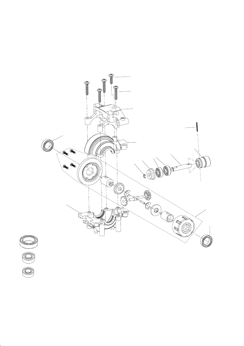
a) Vorderes Differenzial
Die beiden Differenziale für vorn und hinten sind bis auf die Antriebsachse für den Motor baugleich (beim hinteren
Differenzial ist das Hauptzahnrad für den Antrieb durch den Elektromotor montiert).
S1 (10mm)
S2 (15mm), 4x
A1
ST1
K1
SR1
A2
Z1
K2
AC1
A5
A3
A4
K1
K1 (Ø10 x Ø15 x 4)
K2 (Ø5 x Ø11 x 4)
K3 (Ø5 x Ø10 x 4)
Achten Sie darauf, die richtigen Kugellager zu verwenden. Das Kugellager „K3“ ist etwas kleiner und wird für das
hintere Differenzial verwendet.
Das Bauteil „A4“ ist das eigentliche Kegelrad-Differenzial und ist vormontiert (im Bild oben ist das Innenleben zu
sehen).
9
Page 10

Montieren Sie zuerst die Antriebsachse wie im Bild gezeigt. Setzen Sie das Zahnrad „Z1“ in richtiger Orientierung auf
die Achse „AC1“ und fixieren Sie es mit dem kleinen Sicherungsring „SR1“. Anschließend stecken Sie zwei Kugellager
„K2“ (5 x 11 x 4mm) auf die Achse und zuletzt die Kunststoffhülse „A5“ (auf richtige Orientierung achten, die Achse
passt durch die Abflachung nur in einer Position in die Kunststoffhülse).
Sichern Sie dann die Kunststoffhülse „A5“ mit dem langen schwarzen geschlitzten Metallstift „ST1“ auf der Achse.
Z1
SR1
Setzen Sie das Kegelrad-Differenzial „A4“ und die gerade zusammengebaute Antriebsachse in das Gehäuseunterteil „A3“ ein. Geben Sie ein geeignetes Fett (Modellbau-Getriebefett) auf die Zahnflanken der beiden Zahnräder.
Kontrollieren Sie den richtigen Sitz der beiden Kugellager, siehe
Bild rechts.
Setzen Sie das Gehäuseoberteil „A2“ auf, so dass die Kugellager
in den Führungen der Gehäuseteile sitzen.
Zuletzt ist noch das Gehäuseoberteil „A1“ aufzustecken; dann können die Gehäuseteile „A1“, „A2“ und „A3“ verschraubt werden.
Vier lange Schneidschrauben „S2“ (Gewindelänge 15mm) gehören dabei an den Rand, die eine kurze Schneidschraube „S1“
(Gewindelänge 10mm), siehe Bild rechts) gehört oben in die Mitte
des Gehäuseoberteils.
Damit ist das vordere Differenzial fertig.
AC1
K2
A5
ST1
¨
S2 (4x)
A4
A3
A2
A3
A1
S1
10
Page 11
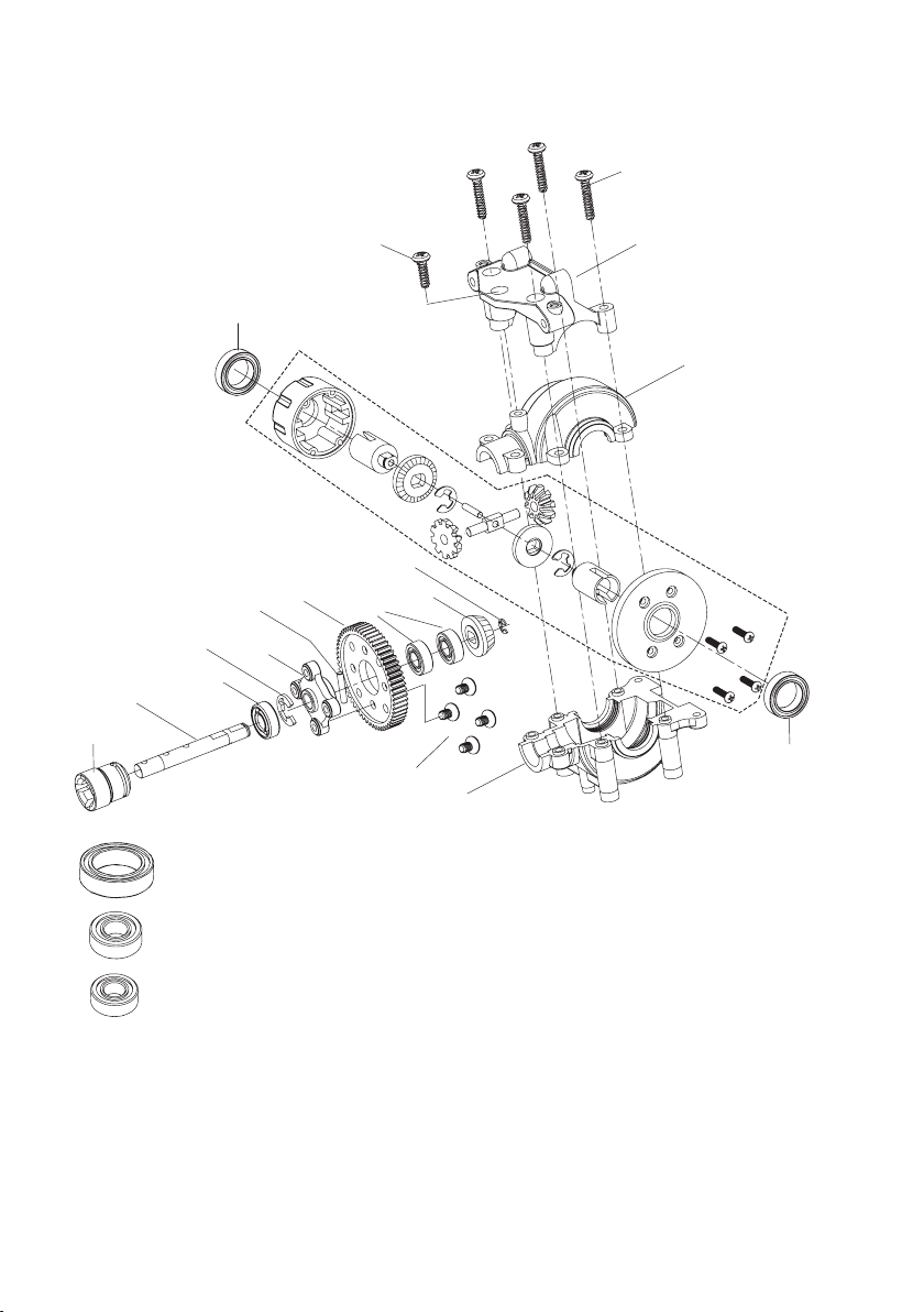
b) Hinteres Differenzial
S2 (15mm), 4x
A5
SR2
AC2
K2
K1 (Ø10 x Ø15 x 4)
K1
ST2
A6
S1 (10mm)
Z2
K3
SR1
S3
A1
A2
A4
Z1
K1
A3
K2 (Ø5 x Ø11 x 4)
K3 (Ø5 x Ø10 x 4)
Achten Sie darauf, die richtigen Kugellager zu verwenden. Das Kugellager „K3“ ist etwas kleiner als „K2“ und wird auf
der Seite zwischen Sicherungsring „SR2“ und Kunststoffhülse „A5“ gesteckt.
Das Bauteil „A4“ ist das eigentliche Kegelrad-Differenzial und ist vormontiert.
11
Page 12
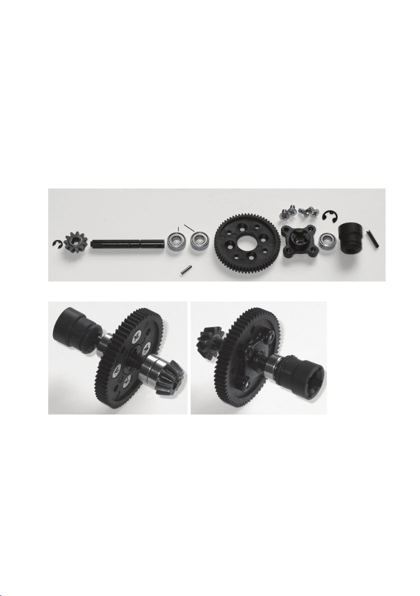
Montieren Sie zuerst die Antriebsachse wie im Bild gezeigt. Setzen Sie das Zahnrad „Z1“ in richtiger Orientierung auf
die Achse „AC2“ und fixieren Sie es mit dem kleinen Sicherungsring „SR1“. Anschließend stecken Sie zwei Kugellager
„K2“ (5 x 11 x 4mm) auf die Achse.
Verschrauben Sie das Zahnrad „Z2“ und den Mitnehmer „A6“ mittels den vier kurzen Senkkopfschrauben „S3“.
Stecken Sie dann den kurzen chromfarbigen Stift „ST2“ in die entsprechende Öffnung der Achse „AC2“. Schieben Sie
dann das fertig montierte Zahnrad „Z2“ mit dem Mitnehmer „A6“ auf die Achse „AC2“, und zwar so, dass die kreuzförmige Öffnung des Mitnehmers „A6“ den Stift „ST2“ umfasst. Zwischen der Achse „AC2“ und dem Mitnehmer „A6“
erfolgt dadurch die Kraftübertragung mittels dem Stift „ST2“.
Sichern Sie den Mitnehmer „A6“ und das Zahnrad „Z2“ über den Sicherungsring „SR2“.
Zuletzt wird noch das einzelne kleine Kugellager „K3“ auf die Achse „AC2“ gesteckt und die Kunststoffhülse „A5“ (auf
richtige Orientierung achten, die Achse passt durch die Abflachung nur in einer Position in die Kunststoffhülse).
Sichern Sie dann die Kunststoffhülse „A5“ mit dem langen schwarzen geschlitzten Metallstift „ST1“ auf der Achse.
Z2
SR1 Z1
Hier nochmals Detailbilder von beiden Seiten der fertig zusammengebauten hinteren Antriebsachse:
Achten Sie vor allem auf die richtige Anordnung des Mitnehmers „A6“ im Zahnrad „Z2“ und wie diese Kombination
dann auf die Achse „AC2“ gesteckt wird.
Vergessen Sie nicht, den Stift „ST2“ in das entsprechende Loch der Achse „AC2“ zu stecken und die Kombination aus
„A6“ und „Z2“ dann mit dem Sicherungsring „SR2“ zu fixieren.
AC2
K2
ST2
S3 (4x)
A6
SR2
K3
A5
ST1
12
Page 13

Setzen Sie das Kegelrad-Differenzial „A4“ und die gerade zusammengebaute Antriebsachse in das Gehäuseunterteil
„A3“ ein. Geben Sie ein geeignetes Fett (Modellbau-Getriebefett) auf die Zahnflanken der beiden Zahnräder des
Differenzials.
Kontrollieren Sie den richtigen Sitz der beiden inneren Kugellager,
siehe Bild rechts.
Setzen Sie das Gehäuseoberteil „A2“ auf, so dass die Kugellager
in den Führungen der Gehäuseteile sitzen.
A4
A3
A2
A3
Zuletzt ist noch das Gehäuseoberteil „A1“ aufzustecken; dann können die Gehäuseteile „A1“, „A2“ und „A3“ verschraubt werden.
Vier lange Schneidschrauben „S2“ (Gewindelänge 15mm) gehören dabei an den Rand, die eine kurze Schneidschraube „S1“
(Gewindelänge 10mm), siehe Bild rechts) gehört oben in die Mitte
des Gehäuseoberteils.
Damit ist das hintere Differenzial fertig.
S2 (4x)
A1
S1
13
Page 14

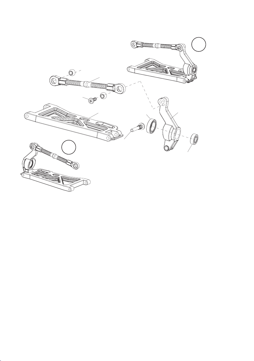
c) Querlenker vorn
B6
B5
B4
R
K2
B3
K1
B2
L
B1
Zwei Kugelkopfschrauben „B4“ werden in je einen Achsschenkel „B3“ gesteckt. Anschließend wird jede davon über
eine Gleithülse „B5“ und eine Kunststoff-Madenschraube „B6“ fixiert.
Achten Sie beim Einlegen der Gleithülse „B5“ auf die richtige Orientierung; gleiches gilt für die Madenschraube „B6“.
Wenn Sie sich die Madenschraube „B6“ genauer ansehen, so ist auf
einer Seite eine Öffnung, in die die Gleithülse genau hineinpasst.
Diese Seite der Madenschraube „B6“ muss in Richtung Gleithülse
„B5“ zeigen!
Drehen Sie die Madenschraube „B6“ mittels einem Sechskantschlüssel nicht mit Gewalt fest, sondern gerade so weit, dass die
Kugelkopfschraube „B4“ nicht wackelt aber auch nicht fest fixiert ist.
Achten Sie auf die richtige Anordnung der Achsschenkel für die linke und rechte Seite
des Fahrzeugs. Das Bild rechts zeigt den rechten Achsschenkel.
Mit einem kleineren Sechskantschlüssel lassen sich die Kugelkopfschrauben in die
Querlenker eindrehen.
Drehen Sie die Kugelkopfschrauben etwa 2/3 der Gewindelänge in die Querlenker.
14
Page 15
d) Querlenker hinten
S4 (M3x10)
R
B8
B9
L
B10
K1
B7
K2
Achten Sie wie schon bei den vorderen Querlenkern auf die richtige Anordnung der Achsschenkel.
Der obere Querlenker „B8“ ist bereits vormontiert.
Die Fixierung der oberen Querlenker an den Achsschenkeln geschieht mit Schrauben M3x10mm.
15
Page 16
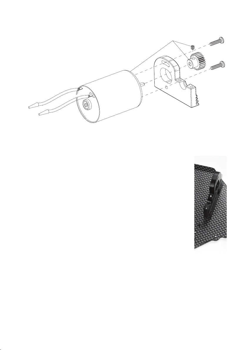
e) Motorhalter und Motor
Der Elektromotor wird mit zwei Schrauben M3x12mm am Motorhalter befestigt. Anschließend wird das Ritzel am
Motor mit einer Madenschraube befestigt. Eine Seite der Motorwelle ist dazu abgeflacht, so kann sich das Zahnrad
nicht verdrehen.
Befestigen Sie den Motorhalter am Chassis, dazu sind drei Senkkopf-Schrauben M3x8mm erforderlich. Das Bild rechts zeigt den Motorhalter ohne Motor.
Die genaue Ausrichtung des Motors am Motorhalter (Zahnflankenspiel) und die Position des
Ritzels auf der Motorwelle ist nach der Montage der beiden Differenziale (Kapitel 7. f und g)
durchzuführen.
Das Motorritzel muss das Hauptzahnrad vollständig überdecken, es darf nicht zu weit vorn oder
hinten auf der Motorwelle sitzen.
Der Abstand zwischen Ritzel und Hauptzahnrad muss später so gering wie möglich eingestellt
werden.
Die beiden Zahnräder dürfen aber nicht streng laufen! Dabei kommt es zu erhöhtem Verschleiß
des Hauptzahnrads, außerdem geht Leistung verloren (der Motor benötigt bereits viel Kraft, das
Hauptzahnrad zu drehen).
Bei einem zu großen Abstand zwischen Ritzel und Hauptzahnrad werden die Zähne des Hauptzahnrads bereits nach kurzer Fahrzeit durch das Ritzel abgeschert/abgerissen!
16
Page 17

f) Differenziale am Chassis montieren
Schrauben Sie zwei Querlenkerhalter an das Vorderteil der Chassisplatte. Benutzen Sie dazu 4 Senkkopf-Schneidschrauben (Gewindelänge 8mm).
Auf den Querlenkerhaltern finden Sie eine Markierung „A“ und „B“
(siehe Kreismarkierung im Bild rechts).
Achten Sie auf die richtige Orientierung beim Festschrauben; kontrollieren Sie die richtige Position; die Löcher in der Chassisplatte für die
Befestigung des Differenzials müssen freiliegen und dürfen nicht verdeckt sein.
Befestigen Sie das vordere Differenzial mit vier Senkkopf-Schneidschrauben (Gewindelänge 10mm).
B
A
Verfahren Sie bei der Montage der hinteren Querlenkerhalter genauso wie bei den vorderen.
Bevor Sie das hintere Differenzial festschrauben, setzen Sie die Kardanwelle zwischen den beiden Differenzialen ein.
Erst danach darf das hintere Differenzial mit vier Senkkopf-Schneidschrauben (Gewindelänge 10mm) am Chassis befestigt werden.
Verstellen Sie ggf. den Motor an der Motorhalterung, so dass sich
das Differenzial einsetzen lässt.
Stellen Sie jetzt den Abstand zwischen Motorritzel und Hauptzahnrad
ein, siehe Kapitel 7. e).
B
A
17
Page 18

g) Lenkung
C7
SR2
C4
C2
SR1
SR2
C6
C5
C3
C1
18
Page 19

Montieren Sie die beiden Halterungen für die Lenkhebel bzw. den Servosaver wie im Bild auf der vorangegangenen Seite gezeigt.
Die eine lange Servostange „LA2“ wird später zwischen Lenkgestänge und Servoarm montiert.
Mit den Senkkopf-Schrauben „S6“ (M3x6mm) werden die fertig zusammengebauten Halterungen „C1“
auf dem Chassis verschraubt.
Die Schrauben „S4“ (M3x10mm) dienen zur Montage der Servostangen „LA1“ und „LA2“.
Die Schrauben „S5“ (Flachkopf, M3x10mm) dienen
zur Montage der Kunststoffstange „VS1“ am Lenkgestänge („C4“ und „C5“).
Der Servosaver (das Bauteil mit der Feder) dient
später dazu, das Servo vor Beschädigung durch die
von außen auf die Lenkung wirkenden Kräfte zu
schützen.
S4 (M3x10mm)
S5 (M3x10mm)
S6
(M3x6mm)
C1
SR2
C2
VS1
LA2
SR1
C1 C3
C7
SR2
LA1
C6
C5
C4
19
Page 20
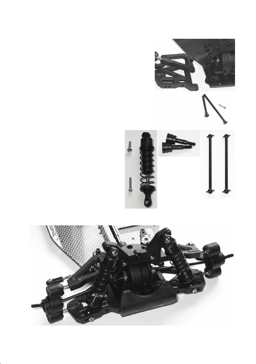
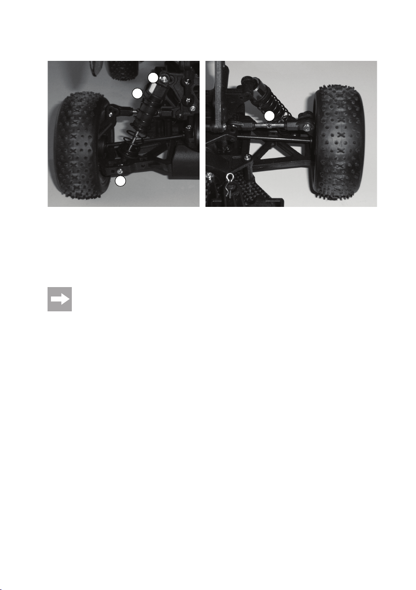
h) Vorderachse: Dämpferbrücke, Querlenker, Stoßdämpfer
Kontrollieren Sie, ob das Kugellager „K1“ richtig im Achsschenkel sitzt
und setzen Sie die Rad-Steckachsen (D) in die Achsschenkel ein.
Fügen Sie den Antriebsknochen (E) zwischen Differenzial und RadSteckachse ein.
Die vordere Dämpferbrücke wird mit zwei Schneidschrauben (A)
(Gewindelänge 10mm) am Differenzial befestigt. Anschließend wird
jeder der beiden Querlenker jeweils mit zwei Steckschrauben (B und
C) wie im Bild gezeigt montiert (die lange Steckschraube ist für den
unteren Querlenker, die kurze für den oberen).
Montieren Sie dann den vorderen Rammschutz mit zwei Senkkopfschrauben (Gewindelänge 8mm).
Zuletzt werden die beiden Stoßdämpfer (F) montiert.
Die M3x12-Schraube (G) dient zur Fixierung des
Stoßdämpfers an der Dämpferbrücke, die Schneidschraube (H, Gewindelänge 15mm) am Querlenker.
Drehen Sie die Schrauben nicht mit Gewalt fest!
Fixieren Sie den Stoßdämpfer an der linken und rechten Fahrzeugseite an den gleichen Montagepositionen/Löchern.
Achten Sie außerdem darauf, dass die Kunststoffhülse am oberen Ende des Stoßdämpfers zur
Dämpferbrücke hin liegt, da sich der Stoßdämpfer
sonst nicht frei bewegen kann.
F
G
H
D
C
A
B
E
20
Page 21

i) Hinterachse: Dämpferbrücke, Querlenker, Stoßdämpfer
Kontrollieren Sie, ob das Kugellager „K1“ richtig im Achsschenkel sitzt
und setzen Sie die Rad-Steckachsen (D) in die Achsschenkel ein.
Fügen Sie den Antriebsknochen (E) zwischen Differenzial und RadSteckachse ein.
Die hintere Dämpferbrücke wird mit zwei Schneidschrauben (A)
(Gewindelänge 10mm) am Differenzial befestigt. Anschließend wird
jeder der beiden Querlenker jeweils mit zwei Steckschrauben (B und
C) wie im Bild gezeigt montiert (die lange Steckschraube ist für den
unteren Querlenker, die kurze für den oberen).
Montieren Sie dann den hinteren Rammschutz mit zwei Senkkopfschrauben (Gewindelänge 8mm). Zusätzlich ist noch eine
Versteifungsstrebe mit zwei Schneidschrauben (Gewindelänge 10mm)
zwischen Rammschutz und Dämpferbrücke einzufügen.
Zuletzt werden die beiden Stoßdämpfer (F) montiert.
Die M3x12-Schraube (G) dient zur Fixierung des
Stoßdämpfers an der Dämpferbrücke, die Schneidschraube (H, Gewindelänge 15mm) am Querlenker.
Drehen Sie die Schrauben nicht mit Gewalt fest!
Fixieren Sie den Stoßdämpfer an der linken und rechten Fahrzeugseite an den gleichen Montagepositionen/Löchern.
Achten Sie außerdem darauf, dass die Kunststoffhülse am oberen Ende des Stoßdämpfers zur
Dämpferbrücke hin liegt, da sich der Stoßdämpfer
sonst nicht frei bewegen kann.
F
G
H
D
B
C
A
E
21
Page 22
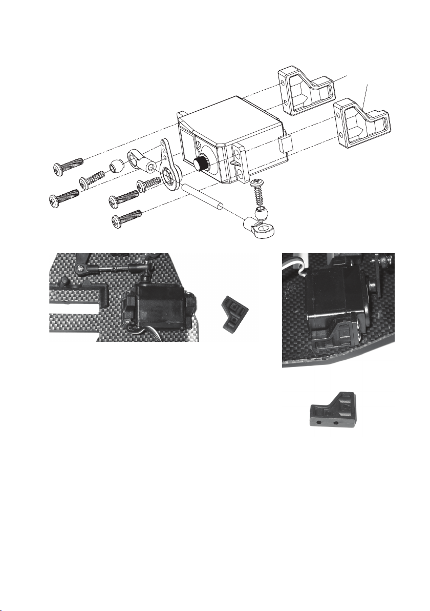
j) Lenkservo
SE1
Das Lenkservo (nicht im Lieferumfang, muss getrennt bestellt werden) wird
mittels den beiden Haltewinkeln „SE1“ auf dem Chassis befestigt. Zwischen
Servoarm und Lenkgestänge wird noch mit zwei Schrauben M3x10 die verstellbare Servostange montiert.
Die spätere Ausrichtung des Servoarms auf der Servoachse bzw. die Einstellung der Servostange ist nach Fertigstellung des Fahrzeugs (Einbau eines Fahrtreglers und einer Fernsteuerung) durchzuführen. Dazu muss ggf.
das Servo nochmals ausgebaut werden, um den Servoarm auf der
Servoachse verstellen zu können.
Die Haltewinkel mit dem Servoarm werden mit 4 Senkkopf-Schneidschrauben
(Gewindelänge 8mm) am Chassis befestigt.
22
Page 23
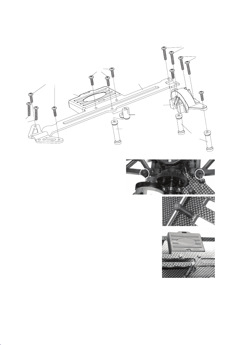
k) Getriebeabdeckung, Chassisbrücke
S1
S4
M3 x 10mm
EH1
S2
Zuerst werden die beiden kurzen Haltebolzen „HA1“ und der
lange Haltebolzen „HA2“ auf dem Chassis montiert; verwenden Sie dazu Senkkopf-Schneidschrauben, Gewindelänge
8mm.
Danach kann die Chassisbrücke „CB1“ montiert werden.
Die beiden Schrauben „S4“ (M3x10) werden mit den Halterungen der Lenkhebel verschraubt.
Die beiden Schrauben „S7“ (M3x15) werden durch die
Chassisbrücke und die Getriebeabdeckung hindurch mit der
Motorhalterung verschraubt.
Je 2 lange Schneidschrauben „S2“ (Gewindelänge 15mm) sind
vorn und hinten mit dem Differenzialgehäuse zu verschrauben.
Zuletzt werden noch 5 Schneidschrauben „S1“ (Gewindelänge
10mm) mit den Haltebolzen und der Empfängerhalterung
„EH1“ verschraubt, so dass die Montage der Chassisbrücke
abgeschlossen ist.
Die Halterung „AN1“ für das Antennenröhrchen wird zwischen
„HA2“ und „CB1“ eingefügt.
HA2
CB1
HA1
S7
M3 x 15mm
S2
S1
S1
GA1
AN1
HA1
HA1
HA2
EH1
23
Page 24
l) Akkuhalterung
Montieren Sie die Akkuhalterungen links und rechts der 6 Öffnungen im Chassis. Verwenden Sie dazu je 2 SenkkopfSchneidschrauben (Gewindelänge 8mm).
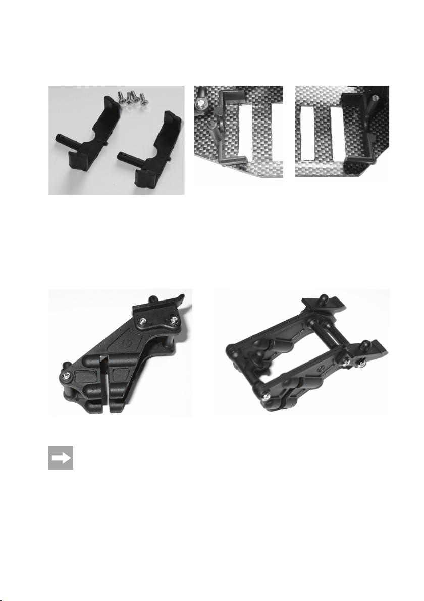
m) Heckspoiler-Halterung
An der Halterung für den Heckspoiler ist auch ein Stift für die Fixierung der Karosserie. Setzen Sie die beiden Seitenteile wie im Bild gezeigt zusammen. Das linke Seitenteil ist mit „L“ gekennzeichnet, das rechte mit „R“. Verwenden Sie
dazu insgesamt 6 Schneidschrauben (Gewindelänge 12mm).
Die fertig zusammengebaute Halterung wird über die hintere Dämpferbrücke gesteckt und dann mit vier langen Schneidschrauben (Gewindelänge 15mm) fixiert.
Befestigen Sie den mitgelieferten Heckspoiler mit zwei Splinten an der Heckspoiler-Halterung.
Die Neigung des Heckspoilers lässt sich durch die in der Halterung integrierte Mechanik in mehreren
Stufen verstellen.
24
Page 25
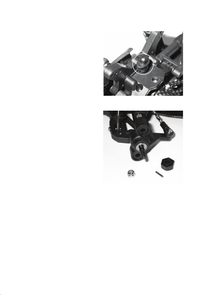
n) Vordere Karosseriehalterung
Für die vordere Karosseriehalterung ist an der vorderen
Dämpferbrücke noch ein kleines Kunststoffteil (siehe Kreis
im Bild rechts) mit einer Schneidschraube zu fixieren. Später
wird hier die Karosserie mit einem Splint gesichert.
o) Radmitnehmer und Räder
Setzen Sie die übrigen Kugellager „K2“ in alle Achsschenkel ein, falls noch nicht geschehen. Anschließend ist der
Metallstift in die Öffnung der Radachse zu stecken. Über
diesen Stift wird noch die Kunststoffmutter gesteckt.
Achten Sie dabei darauf, dass die Mutter richtig aufgesteckt
wird - die geschlitzte Seite muss über den Metallstift geschoben werden.
Zuletzt ist auf jede Achse ein Rad aufzustecken und die
Stoppmutter aufzuschrauben. Achten Sie hier auf die richtige Orientierung der Stoppmutter - die abgerundete Seite
liegt nach außen hin.
25
Page 26

p) Empfänger und Fahrtregler
Diese Bauteile sind nicht im Lieferumfang. Der Empfänger ist bei Ihrer Fernsteuerung dabei, der Fahrtregler muss getrennt bestellt werden.
Der Empfänger wird von der Unterseite der Empfängerhalterung „EH1“ her mit doppelseitigem Klebeband fixiert.
Zusätzlich ist er mit einem Kabelbinder zu sichern, der durch die Schlitze der Empfängerhalterung gesteckt wird.
Dadurch kann sich der Empfänger nicht lösen.
Der Fahrtregler wird auf der Oberseite der Chassisbrücke „CB1“ mit doppelseitigem Klebeband montiert. Achten Sie
dabei darauf, dass sich die Karosserie noch aufsetzen lässt!
Der Schalter des Fahrtreglers kann ebenfalls mit einem doppelseitigen Klebeband fixiert werden, z.B. auf dem
Lenkservo.
Führen Sie das Antennenkabel des Empfängers durch die Halterung „AN1“ und dann durch das Antennenröhrchen.
Stecken Sie das Antennenröhrchen in die Halterung „AN1“. Fixieren Sie das Antennenkabel am oberen Ende des
Antennenröhrchens mit einer Gummikappe.
Achten Sie beim Verlegen des Antennenkabels darauf, dass es nicht in die Kardanwelle oder andere drehende Teile
gelangt. Kürzen Sie das Antennenkabel niemals!
Verbinden Sie das Lenkservo und den Fahrtregler mit dem Empfänger. Beachten Sie hierbei die Bedienungsanleitung der Fernsteuerung, an welchen Anschlüssen Lenkservo und Fahrtregler angesteckt werden müssen.
26
Page 27
8. Fahrwerk einstellen
Nach dem Zusammenbau ist noch das Fahrwerk einzustellen.
Die Erläuterung der Zusammenhänge zwischen Chassis-Setupeinstellungen und Fahrverhalten sind sehr komplex
und würden den Rahmen dieser Anleitung sprengen. Aus diesem Grund können hier nur die zur Verfügung stehenden Einstellmöglichkeiten aufgezeigt werden.
Für weitere Informationen müssen wir Sie an einschlägige Fachzeitschriften sowie auf die umfangreichen Fachbücher zu diesem Thema verweisen.
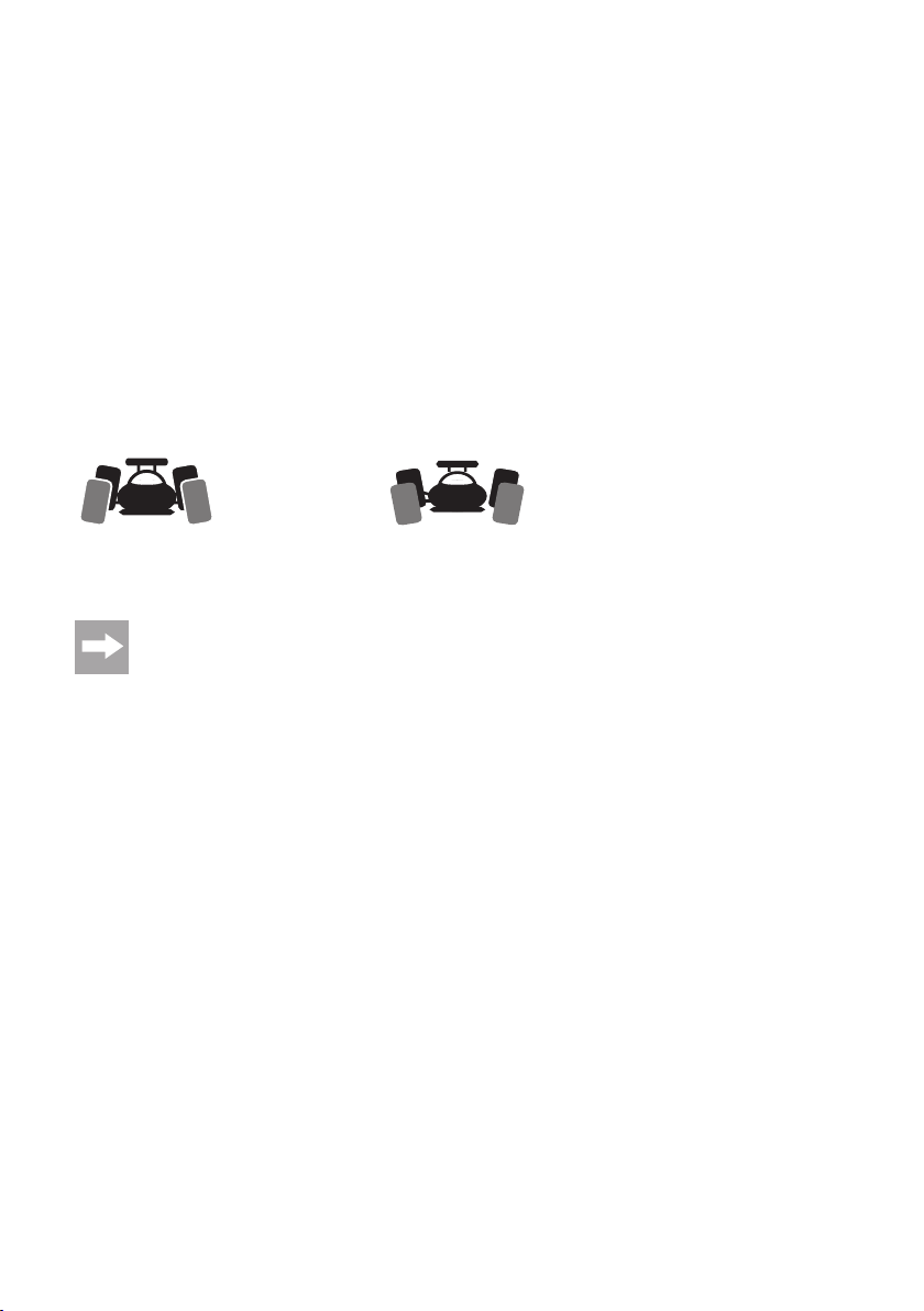
a) Einstellung des Radsturzes
Der Radsturz bezeichnet die Neigung der Radebene gegenüber der Senkrechten.
Negativer Sturz Positiver Sturz
(Radoberkanten zeigen nach innen) (Radoberkanten zeigen nach außen)
Die Einstellung der Räder bei den beiden Abbildungen oben ist übertrieben dargestellt, um Ihnen den
Unterschied zwischen negativem und positivem Sturz zu zeigen. Für die Einstellung am Modellfahrzeug
sollte eine so extreme Einstellung natürlich nicht vorgenommen werden!
Negativer Sturz an den Vorderrädern erhöht die Seitenführungskräfte der Räder bei Kurvenfahrten, die Lenkung
spricht direkter an, die Lenkkräfte werden geringer. Gleichzeitig wird das Rad in Achsrichtung auf den Achsschenkel
gedrückt. Damit wird axiales Lagerspiel ausgeschaltet, das Fahrverhalten wird ruhiger.
Negativer Sturz an den Hinterrädern vermindert die Neigung des Fahrzeughecks in Kurven auszubrechen.
Ein positiver Sturz vermindert dagegen die Seitenführungskräfte der Reifen und sollte nicht verwendet werden.
27
Page 28

b) Einstellung der Spur
Die Spur (Vorspur = Bild „a“, Nachspur = Bild „b“) bezeichnet die Stellung der Radebene zur Fahrtrichtung.
Während der Fahrt werden die Räder durch den Rollwiderstand vorne
auseinandergedrückt und stehen daher nicht mehr exakt parallel zur
Fahrtrichtung. Zum Ausgleich können die Räder des stehenden Fahrzeuges so eingestellt werden, dass sie vorne leicht nach innen zeigen.
Diese Vorspur bewirkt gleichzeitig eine bessere Seitenführung des
Reifens und damit ein direkteres Ansprechen der Lenkung.
Wird ein weicheres Ansprechen der Lenkung gewünscht, kann dies
entsprechend über die Einstellung einer Nachspur erreicht werden, d.h.,
die Räder des stehenden Fahrzeugs zeigen nach außen. Ein Spurwinkel von 0° an der Vorderachse sorgt für die beste Fahrbarkeit auf
fast jedem Untergrund.
Ein Spurwinkel von mehr als 3° Vorspur (a) oder Nachspur (b) führt zu Problemen im Handling und verminderter
Geschwindigkeit.
Die Vorspur der Vorderräder sollte 4° nicht überschreiten; die obigen Bilder zeigen eine stark übertriebene
Einstellung, die nur zur Verdeutlichung des Unterschieds zwischen Vor- und Nachspur dient.
a
b
¦¦
28
Page 29
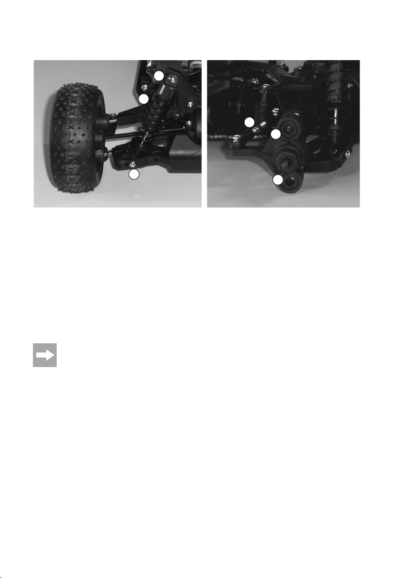
c) Vorderachse
A
C
F
D
B
• Die Stoßdämpfer können an den oberen (A) und unteren (B) Aufnahmepunkten an verschiedenen Positionen montiert werden.
• Der Stoßdämpfer selbst kann z.B. durch das Einfügen von Clipsen in seiner Dämpfung verstellt werden (C) bzw. es
kann der Federweg begrenzt werden.
• Der Radsturz kann verändert werden, indem die Einstellung am oberen (D) oder unteren (E) Querlenker verändert
wird.
Dazu ist ein kleiner Sechskant-Schlüssel erforderlich, mit dem die Kugelschraube am oberen bzw. unteren Querlenker verdreht wird. Achten Sie hierbei darauf, dass etwa mindestens 2/3 der Gewindelänge der Kugelkopfschraube
im Querlenker verbleibt und dass sich der Antriebsknochen nicht löst (Kugelkopfschrauben zu weit herausgedreht)
bzw. zu streng läuft (Kugelkopfschrauben zu weit eingedreht).
• Die Spurstange (F) für das Lenkgestänge dient zum Einstellen der Vor- bzw. Nachspur.
Neben den oben beschriebenen Einstellmöglichkeiten können z.B. andere Stoßdämpfer bzw. Federn
verwendet werden, sowie Dämpferöle, deren unterschiedliche Viskosität das Federverhalten beeinflussen.
E
29
Page 30
d) Hinterachse
A
C
D
B
• Die Stoßdämpfer können an den oberen (A) und unteren (B) Aufnahmepunkten an verschiedenen Positionen montiert werden.
• Der Stoßdämpfer selbst kann durch das Einfügen von Clipsen in seiner Dämpfung verstellt werden (C) bzw. es kann
der Federweg begrenzt werden.
• Der Radsturz kann verändert werden, indem der obere Querlenker mittels einer Gewindestange mit Loch (D) verstellt wird.
Neben den oben beschriebenen Einstellmöglichkeiten können z.B. andere Stoßdämpfer bzw. Federn
verwendet werden, sowie Dämpferöle, deren unterschiedliche Viskosität das Federverhalten beeinflussen.
30
Page 31

9. Akkupack aufladen
Bitte beachten Sie:
Im Lieferumfang ist kein Akkupack für das Fahrzeug enthalten, dieser muss getrennt bestellt werden.
Der Akkupack ist bei Lieferung in der Regel leer und muss aufgeladen werden.
Bevor ein Akkupack seine maximale Leistung bringt, sind mehrere vollständige Entlade- und Ladezyklen
erforderlich.
Fahren Sie einen NiCd-Akkupack nach Möglichkeit immer leer, da es beim mehrmaligen Aufladen eines
”halbvollen“ NiCd-Akkupacks zum sog. Memory-Effekt kommen kann. Das bedeutet, dass der Akkupack
seine Kapazität verliert, er gibt nicht mehr die ganze gespeicherte Energie ab, die Fahrzeit wird geringer.
Bei Akkus mit NiMH-Technik ist dieser Effekt viel geringer, ein Aufladen von teilentladenen Akkus unproblematischer.
Hochwertigere Akkupacks haben nicht nur eine höhere Kapazität, so dass Sie länger mit dem Modellfahrzeug fahren können, sondern auch eine höhere Ausgangsspannung bei Belastung. Somit steht für
den Motor mehr Leistung zur Verfügung, was sich in einer besseren Beschleunigung und einer höheren
Geschwindigkeit zeigt.
Wenn Sie mehrere Akkupacks oder Akkus verwenden, kann sich die Anschaffung eines hochwertigen
Ladegeräts lohnen. Dieses bietet normalerweise auch eine Schnellladung für Akkus an.
Akkus erwärmen sich beim Laden oder Entladen (beim Fahren des Fahrzeugs). Laden Sie Akkus erst
dann, wenn diese sich auf Zimmertemperatur abgekühlt haben. Gleiches gilt nach dem Ladevorgang;
benutzen Sie den Akku im Fahrzeug erst dann, wenn der Akku sich nach dem Ladevorgang ausreichend
abgekühlt hat.
31
Page 32

10. Inbetriebnahme
a) Abnehmen der Karosserie
Die Karosserie wird mit Halteklammern gesichert, die aus den Haltebolzen herausgezogen werden müssen. Anschließend kann die Karosserie nach oben abgehoben werden.
b) Akkupack in das Fahrzeug einsetzen
Achtung!
Der Akkupack darf noch nicht mit dem Fahrtregler verbunden werden!
Auf einer Seite des Fahrzeugs befindet sich die Halterung für den Akkupack. Die Fixierung der Akkupacks geschieht
über eine Kunststoffstrebe, die mit zwei Halteklammern gesichert wird.
Legen Sie den Akkupacks so ein, dass das Anschlusskabel des Akkus nicht in die Lenkmechanik bzw. den Antrieb
gelangen kann.
c) Akkus/Batterien in die Fernsteuerung (Sender) einlegen
Falls noch nicht geschehen, legen Sie Akkus bzw. Batterien in Ihre Fernsteuerung (Sender) ein. Beachten Sie dazu
die Bedienungsanleitung zu Ihrer Fernsteuerung.
d) Fernsteuerung (Sender) einschalten
Bevor der Akkupack im Fahrzeug mit dem Fahrtregler verbunden werden darf, ist immer zuerst die Fernsteuerung
(Sender) einzuschalten. Kontrollieren Sie den Zustand der dort eingelegten Batterien bzw. Akkus.
e) Akkupack am Fahrtregler anschließen
Bevor Sie einen Akkupack am Fahrtregler anschließen, nehmen Sie die Fernsteuerung (Sender) in Betrieb (siehe
Kapitel 9. c) und 9. d).
Um ein plötzliches Anlaufen des Antriebs und somit ein unkontrolliertes Losfahren des Fahrzeugs zu
verhindern (z.B. wenn die Trimmung für den Antrieb verstellt ist), setzen Sie das Fahrzeug auf eine geeignete Unterlage (z.B. Startbox), damit sich der Antrieb frei drehen kann.
Schalten Sie Ihren Fahrtregler aus.
Schließen Sie dann den Akkupack am Fahrtregler an.
32
Page 33

f) Fahrtregler einschalten
Nehmen Sie zuerst die Fernsteuerung (Sender) in Betrieb, siehe Kapitel 9. c) und 9. d), falls noch nicht geschehen!
Schalten Sie erst jetzt Ihren Fahrtregler ein.
Ggf. ist eine Programmierung Ihres Fahrtreglers erforderlich, um die Neutralstellung bzw. die Vollgasstellung für Vorwärts- und Rückwärtsfahrt festzulegen.
g) Antriebs- und Lenkfunktionen prüfen
Prüfen Sie vor jeder Fahrt, ob die Einstellungen an der Fernsteuerung (Sender) korrekt sind und ob das Fahrzeug
entsprechend den Steuerbefehlen richtig reagiert.
Wie bereits in Kapitel 9. e) beschrieben, ist das Fahrzeug dazu auf eine geeignete Unterlage (z.B. Startbox) zu setzen, damit sich der Antrieb frei drehen kann.
• Stellen Sie an Ihrer Fernsteuerung die Trimmung für den Antrieb so ein, dass sich der Antrieb nicht bewegt, wenn
der Gas-/Bremshebel in der Neutralstellung ist.
• Stellen Sie die Trimmung für die Lenkung so ein, dass die Vorderräder gerade stehen, wenn das Drehrad Ihrer
Fernsteuerung in Mittelstellung steht.
Falls der Trimmweg dazu nicht ausreicht, ist der Servohebel auf der Servoachse zu verstellen oder die Servostange
„LA2“ zu verdrehen (siehe Kapitel 7. g).
• Kontrollieren Sie die richtige Reaktion der Lenkung auf Ihre Fernsteuerung. Sollte die Reaktion der Lenkung z.B. bei
Verwendung einer Pistolengriff-Fernsteuerung gegenläufig sein (Drehrad nach links, Lenkeinschlag nach rechts),
so aktivieren Sie die Reverse-Funktion.
Gleiches gilt bei der Vorwärts-/Rückwärtsfahrt. Wenn der Fahrtregler über eine Bremsfunktion verfügt, kann es
erforderlich werden, nicht nur die Reverse-Funktion an der Fernsteuerung zu aktivieren, sondern auch die beiden
Motorkabel zu vertauschen (zwischen Motor und Fahrtregler).
Beachten Sie dazu die Bedienungsanleitung zu Ihrer Fernsteuerung.
h) Karosserie aufsetzen und befestigen
Führen Sie das Antennenröhrchen von der Unterseite der Karosserie durch die vorgesehene Öffnung. Sollte noch
keine Öffnung vorgesehen sein, so lässt sich diese an der entsprechenden Stelle mittels einem geeigneten Werkzeug
leicht herstellen.
Setzen Sie die Karosserie auf die Halterungen auf und sichern Sie diese mit den zu Beginn entfernten Halteklammern.
Ihr Fahrzeug ist jetzt für die erste Testfahrt bereit!
33
Page 34

i) Fahrt beenden
Um das Fahren zu beenden, gehen Sie wie folgt vor:
• Lassen Sie das Fahrzeug ausrollen.
• Nachdem das Fahrzeug still steht, nehmen Sie die Karosserie ab und schalten Sie das Fahrzeug aus (Schalter des
Fahrtreglers z.B. in die Stellung „OFF“ bringen).
Fassen Sie dabei nicht in die Räder oder den Antrieb und bewegen Sie auf keinen Fall den Bedienhebel
für die Fahrfunktion an der Fernsteuerung (Sender)!
• Trennen Sie den Akkupack vom Fahrtregler. Lösen Sie die Steckverbindung vollständig.
• Erst jetzt darf die Fernsteuerung (Sender) ausgeschaltet werden.
Achtung!
Motor, Fahrtregler und Akkupack werden beim Betrieb sehr warm! Fassen Sie deshalb diese Teile unmittelbar nach der Fahrt nicht an, Verbrennungsgefahr!
Beenden Sie das Fahren sofort, wenn Sie ungewöhnliche Reaktionen des Fahrzeugs auf die Steuerbefehle der Fernsteuerung feststellen oder wenn das Fahrzeug nicht mehr reagiert.
Dieses Verhalten könnte durch einen schwachen Fahrzeugakku, schwache Batterien/Akkus in der Fernsteuerung oder einem zu hohen Abstand zwischen Fahrzeug und Fernsteuerung verursacht werden.
Auch eine nicht vollständig herausgezogene Antenne an der Fernsteuerung, Störungen auf dem verwendeten Funkkanal (z.B. andere Modelle, Funkübertragungen durch andere Geräte) oder ungünstige Sende-/Empfangsbedingungen können eine Ursache für ungewöhnliche Reaktionen des Fahrzeugs sein.
j) Tragen des Fahrzeugs
Durch Funkstörungen, ungewollte Betätigung der Fernsteuerung oder durch einen anderen Sender auf dem gleichen
Kanal könnte es zu unvorhergesehenen Reaktionen des Fahrzeugs kommen.
34
Deshalb ist unbedingt darauf zu achten, dass Sie nicht in den Antrieb hineinfassen, wenn das Fahrzeug
an seine Startposition gestellt werden soll oder wenn Sie es vom Boden aufheben wollen.
Page 35

11. Reinigung und Wartung
a) Allgemein
Vor einer Reinigung oder Wartung ist das Fahrzeug auszuschalten und der Akkupack vom Fahrregler
vollständig zu trennen. Falls Sie vorher mit dem Fahrzeug gefahren sind, lassen Sie alle Teile (z.B. Motor,
Fahrtregler usw.) zuerst vollständig abkühlen.
Reinigen Sie das ganze Fahrzeug nach dem Fahren von Staub und Schmutz, verwenden Sie z.B. einen langhaarigen
sauberen Pinsel und einen Staubsauger. Druckluft-Sprays können ebenfalls eine Hilfe sein.
Verwenden Sie keine Reinigungssprays oder herkömmliche Haushaltsreiniger. Dadurch könnte die Elektronik beschädigt werden, außerdem führen solche Mittel zu Verfärbungen an den Kunststoffteilen oder
der Karosserie.
Zum Abwischen der Karosserie kann ein weiches, leicht angefeuchtetes Tuch verwendet werden. Reiben Sie nicht zu
fest, sonst gibt es Kratzspuren.
Durch die Motorvibrationen und Erschütterungen beim Fahren können sich Teile und Schraubverbindungen lösen.
Überprüfen Sie deshalb den festen Sitz der Radmuttern und aller Schraubverbindungen nach bzw. vor jeder Fahrt.
Gleiches gilt für andere Teile des Fahrzeugs.
Drehen Sie die Schrauben jedoch nicht mit Gewalt fest! Schrauben, die in Kunststoffteilen sitzen, werden
dabei überdreht, wodurch sie nicht mehr fest sitzen.
Werden beispielsweise die Radmuttern mit Gewalt angezogen, verklemmt dies die Kugellager/Radlager,
was zu erhöhtem Stromverbrauch des Elektromotors und der Überhitzung von Fahrtregler und Elektromotor sowie einer Verringerung der Geschwindigkeit führt.
Kontrollieren Sie, ob die Reifen noch richtig auf der Felge sitzen oder ob sich die Verklebungen gelöst haben.
Schmierung bedarf hauptsächlich das Differenzial, wie bereits beim Zusammenbau beschrieben. Die anderen Teile
des Fahrzeugs sollten nur von Staub und Schmutz gereinigt werden; ein Einfetten bringt hier kaum Vorteile - dagegen
setzt sich Staub und Schmutz sehr schnell an diesen Teilen ab, was zu erhöhtem Verschleiß führt.
Sollten abgenutzte oder defekte Fahrzeugteile ausgetauscht werden müssen, so verwenden Sie nur Originalersatzteile.
Achten Sie darauf, dass keine Kabel geknickt oder gequetscht werden und dass Kabel nicht in bewegliche Teile bzw.
den Antrieb gelangen.
Überprüfen Sie vor jedem Gebrauch das Modell auf Beschädigungen. Falls Sie Beschädigungen feststellen, so darf
das Fahrzeug nicht verwendet bzw. in Betrieb genommen werden.
35
Page 36

b) Einstellen des Zahnflankenspiels
Das Zahnflankenspiel muss vor der Erstinbetriebnahme richtig eingestellt werden.
Lösen Sie dazu die beiden Befestigungsschrauben des Elektromotors soweit, dass Sie den Motor mit sanftem Druck
in Richtung Hauptzahnrad verschieben können (Schrauben nur leicht lösen, aber nicht herausdrehen!). Dazu ist
vorher ggf. die Abdeckung über den Zahnrädern zu entfernen.
Das Motorritzel und das Hauptzahnrad greifen nun spielfrei ineinander.
Setzen Sie einen dünnen Papierstreifen zwischen das Motorritzel und das Hauptzahnrad, drehen Sie das Hauptzahnrad von Hand so, dass der Papierstreifen zwischen beide Zahnräder eingezogen wird.
Unter dem Druck des Papiers wird der Elektromotor um das erforderliche Maß zurückgedrückt. Drehen Sie nun in
dieser Stellung die Befestigungsschrauben des Motors fest.
Wenn Sie anschließend das Hauptzahnrad zurückdrehen, damit der Papierstreifen wieder entnommen werden kann,
sollten beide Zahnräder den erforderlichen Abstand zueinander aufweisen.
Idealerweise ist das Ritzel so nah wie möglich am Hauptzahnrad, ohne dass sich die Zähne berühren.
Sind die Zahnräder (Ritzel und Hauptzahnrad) zu weit von einander entfernt, so werden bereits nach
wenigen Sekunden Fahrt die Zähne des Hauptzahnrads vom Ritzel regelrecht abgefräst - Verlust von
Garantie/Gewährleistung!
Drückt das Ritzel jedoch gegen das Hauptzahnrad (Getriebe läuft spielfrei), so führt dies zu einem Leistungsverlust, außerdem zu einem erhöhten Stromverbrauch und zu einem vorzeitigen Verschleiß des Hauptzahnrads.
Überprüfen Sie nach jeder Fahrt das Zahnflankenspiel; möglicherweise hat sich auch der Motor durch die Vibrationen
gelöst oder verstellt.
c) Quarzwechsel
In der Reichweite des Senders darf es keine anderen Sender/Modelle mit der gleichen Frequenz geben, da sich die
Sender gegenseitig stören und die Modelle nicht mehr richtig auf die Befehle am Sender reagieren. Sind deshalb in
Ihrer Nähe andere Modelle in Betrieb, so sprechen Sie sich mit deren Besitzern ab, wer welche Frequenz nutzt.
Verwenden Sie ausschließlich für den Sender und Empfänger geeignete Zubehör-Quarze.
Vor einem Quarzwechsel ist zuerst das Fahrzeug und danach die Fernsteuerung (Sender) auszuschalten.
Senderquarze sind mit einem „T“ oder „TX“ gekennzeichnet, Empfängerquarze mit einem „R“ bzw. „RX“. Vertauschen
Sie die Quarze nicht, da andernfalls keine richtige Funktion möglich ist.
36
Page 37

12. Entsorgung
a) Allgemein
Elektrische und elektronische Geräte dürfen nicht in den Hausmüll!
Entsorgen Sie das Produkt am Ende seiner Lebensdauer gemäß den geltenden gesetzlichen Vorschriften.
b) Batterien und Akkus
Sie als Endverbraucher sind gesetzlich (Batterieverordnung) zur Rückgabe aller gebrauchten Batterien und Akkus
verpflichtet; eine Entsorgung über den Hausmüll ist untersagt!
Schadstoffhaltige Batterien/Akkus sind mit nebenstehenden Symbolen gekennzeichnet, die auf das Verbot der Entsorgung über den Hausmüll hinweisen. Die Bezeichnungen für das ausschlaggebende Schwer-
Sie erfüllen damit die gesetzlichen Verpflichtungen und leisten Ihren Beitrag zum Umweltschutz.
metall sind: Cd=Cadmium, Hg=Quecksilber, Pb=Blei (Bezeichnung steht auf Batterie/Akku z.B. unter den
links abgebildeten Mülltonnen-Symbolen).
Ihre verbrauchten Batterien/Akkus können Sie unentgeltlich bei den Sammelstellen Ihrer Gemeinde, unseren Filialen oder überall dort abgeben, wo Batterien/Akkus verkauft werden.
37
Page 38

13. Behebung von Störungen
Auch wenn das Modell nach dem heutigen Stand der Technik gebaut wurde, kann es dennoch zu Fehlfunktionen oder
Störungen kommen. Aus diesem Grund möchten wir Ihnen aufzeigen, wie Sie eventuelle Störungen beseitigen können.
Problem
Das Modell reagiert nicht
Fahrzeug bleibt beim Loslassen des
Bedienhebels für die Fahrfunktion
nicht stehen
Der Geradeauslauf stimmt nicht
Lenkung bzw. Fahrbewegung gegenläufig zur Bewegung von Drehrad und Gashebel des Senders
Fahrzeug wird langsamer bzw.
Lenkservo zeigt nur noch geringe
Reaktionen
Unvorhergesehene Reaktionen des
Fahrzeugs, Antrieb bzw. Servos laufen ohne Grund an, Steuerung funktioniert nicht richtig
Abhilfe
• Akkupack des Fahrzeugs prüfen.
• Akkus/Batterien im Sender prüfen.
• Anschluss des Akkupacks überprüfen.
• Ein-/Ausschalter des Fahrzeugs und Senders prüfen.
• Quarze bezüglich Beschriftung prüfen (gleiche Frequenz, bzw. Sender/Empfängerquarz richtig eingesetzt?).
• Quarzwechsel auf einen anderen Kanal durchführen.
• Stellen Sie mit Hilfe der Trimmung am Sender die Neutralstellung für
die Fahrfunktion richtig ein.
• Stellen Sie mit Hilfe der Trimmung am Sender die Lenkfunktion richtig
ein.
• Überprüfen Sie das Lenkgestänge.
• Spiel in der Lenkung/Radaufhängung überprüfen und gegebenenfalls
ausgeschlagene Teile erneuern .
• Servo-Reverse-Funktionen am Sender prüfen und gegebenenfalls umstellen.
• Akkupack des Fahrzeugs prüfen.
• Senderantenne vollständig ausziehen.
• Antenne des Empfängers abwickeln und richtig verlegen (im senkrecht
montierten Antennenröhrchen).
• Akkus/Batterien im Sender prüfen.
• Akkupack des Fahrzeugs prüfen.
• Quarze bezüglich Beschriftung prüfen (gleiche Frequenz, bzw. Sender/Empfängerquarz richtig eingesetzt?).).
• Quarzwechsel auf einen anderen Kanal durchführen.
• Abstand zwischen Fahrzeug und Sender zu gering bzw. zu groß.
38
Page 39

14. Technische Daten
Maßstab: ................................................... 1:10
Antrieb: ..................................................... Elektromotor Typ 540
Allrad-Antrieb über Kardanwelle
Kugelgelagerter Antrieb
Differenzial in Vorder- und Hinterachse
Federung: ................................................. Einzelradaufhängung, mit je 1 Stoßdämpfer
Abmessungen (L x B x H): ....................... Ca. 400 x 235 x 167mm
Reifen-Abmessungen (B x Ø): ................. Ca. 34 x 87mm
Spur: ......................................................... Ca. 205/200mm (vorn/hinten)
Radstand: ................................................. Ca. 270mm
Gewicht: ....................................................Je nach Ausrüstung ca. 1300-1500g (ohne Fahrakku)
Erforderliches/empfohlenes Zubehör (nicht im Lieferumfang):
Fahrtregler: ............................................... Elektronischer Fahrtregler (Vorwärts/Rückwärts/Bremse) mit BEC
Lenkservo: ................................................ Standard- bzw. Highspeed-Servo, 40x20mm
Fahrakku: .................................................. NiMH-Racingpack, 6 SubC-Zellen, 7.2V
Fernsteueranlage: .................................... 2 Kanäle
39
Page 40

1. Introduction ...................................................................................................................................................... 41
2. Intended Use .................................................................................................................................................... 42
3. Contents ........................................................................................................................................................... 42
4. Symbol Explanation ......................................................................................................................................... 42
5. Safety Instructions ........................................................................................................................................... 43
6. Information on Batteries and Rechargeable Batteries .................................................................................... 46
7. Assembly ..........................................................................................................................................................47
8. Setting the undercarriage ................................................................................................................................ 65
9. Recharging Battery Pack ................................................................................................................................. 69
10. Operation ......................................................................................................................................................... 70
Table of Contents
a) General information ................................................................................................................................... 43
b) Assembly ................................................................................................................................................... 43
c) Operation ................................................................................................................................................... 44
a) Front differential ......................................................................................................................................... 47
b) Rear differential ..........................................................................................................................................49
c) Front suspension arms .............................................................................................................................. 52
d) Rear suspension arms ............................................................................................................................... 53
e) Motor attachment and motor ..................................................................................................................... 54
f) Mounting differentials on the chassis ........................................................................................................ 55
g) Steering ...................................................................................................................................................... 56
h) Front axle: Shock tower, suspension arms, shock absorbers ...................................................................58
i) Rear axle: Shock tower, suspension arms, shock absorbers ................................................................... 59
j) Steering servo ............................................................................................................................................ 60
k) Drive covering, chassis bridge ................................................................................................................... 61
l) Rechargeable battery bracket ................................................................................................................... 62
m) Rear spoiler mount .................................................................................................................................... 62
n) Front body mount ....................................................................................................................................... 63
o) Hubs and wheels ....................................................................................................................................... 63
p) Receiver and drive control unit .................................................................................................................. 64
a) Setting the camber ..................................................................................................................................... 65
b) Setting the alignment ................................................................................................................................. 66
c) Front axle ................................................................................................................................................... 67
d) Rear axle .................................................................................................................................................... 68
a) Removing the car body .............................................................................................................................. 70
b) Placing the rechargeable battery pack in the vehicle ............................................................................... 70
c) Inserting batteries/rechargeable batteries into the remote control (transmitter) ....................................... 70
d) Switching on the remote control (transmitter) ........................................................................................... 70
e) Connecting the rechargeable battery pack to the drive control unit ......................................................... 70
f) Activating the drive control unit.................................................................................................................. 71
Page
40
Page 41

Page
g) Checking the driving and steering function ............................................................................................... 71
h) Mounting and fastening the car body ........................................................................................................ 71
i) Ending use ................................................................................................................................................. 72
j) Carrying the vehicle ................................................................................................................................... 72
11. Cleaning and Maintenance .............................................................................................................................. 73
a) General information ................................................................................................................................... 73
b) Adjusting the tooth profile clearance ......................................................................................................... 74
c) Changing crystal ........................................................................................................................................ 74
12. Disposal ........................................................................................................................................................... 75
a) General information ................................................................................................................................... 75
b) Batteries and rechargeable batteries ........................................................................................................ 75
13. Troubleshooting ............................................................................................................................................... 76
14. Technical Data ................................................................................................................................................. 77
1. Introduction
Dear Customer,
Thank you for purchasing this product.
This product complies with all current national and European requirements.
These operating instructions are part of this product. They contain important information regarding
installation and operation. Please bear this in mind in case you pass it on the product to a third
party.
Therefore, keep these operating instructions for future reference!
All company names and product names are trademarks of the respective owner. All rights reserved.
In case of any technical inquiries, contact or consult:
Tel. no.: +49 9604 / 40 88 80
Fax. no.: +49 9604 / 40 88 48
E-mail: tkb@conrad.de
Mon. to Thur. 8.00am to 4.30pm, Fri. 8.00am to 2.00pm
41
Page 42

2. Intended Use
This product is a construction kit to make an all-wheel drive model car.
The following components are required for operation (not included in the delivery): Remote control system (transmitter/
receiver), steering servo, drive control unit, rechargeable drive battery (racing pack), batteries/rechargeable batteries
for the remote control system, charger.
The product is not a toy and should be kept out of reach of children under 14 years of age.
Observe all safety instructions given these operating instructions. They contain important
information regarding the handling of the product.
The information provided in these instructions pertain partially to the construction kit and partially
to the constructed vehicle which requires the additional components before it is ready for use
(transmitter/receiver, drive control unit, steering servo, rechargeable drive battery, all not included
in delivery).
3. Contents
• Vehicle construction kit
• Electric motor type 540
• Operating instructions
The spare part list can be found on our Website in the Download domain specific to the corresponding
product.
Alternatively, you can order the spare parts by phone; the contact details are at the beginning of this
operating manual in the chapter "Introduction".
4. Symbol Explanation
The icon with the exclamation mark points out particular dangers associated with handling, function or
operation.
The “arrow“ symbol indicates special tips and operating information.
42
Page 43

5. Safety Instructions
In case of damage caused by not complying with these safety instructions the guarantee will be
rendered void. We will not assume any responsibility for consequential damage!
Nor do we assume liability for damage to property or personal injury caused by improper use or
the failure to observe the safety instructions! In such cases the guarantee will be rendered void.
Normal wear and tear during operation (e.g. worn tires) is excluded from the guarantee, the same
is the case for accidental damage (e.g. broken off suspension arm, scratched or destroyed car
body etc.).
Dear Customer, these safety instructions are not only for the protection of the product but also for your own
safety and that of other people. Therefore read this chapter very carefully before putting the product into
operation!
a) General information
Caution, important note!
Operating the model can lead to material and/or personal damage. Therefore, make sure that you are
properly insured when using the model, e.g. by taking out private liability insurance. If you already have
insurance, enquire whether the operation of the model is covered before operating it.
• The unauthorized conversion and/or modification of the product is prohibited for safety and approval reasons (CE).
• The product is not a toy and should be kept out of reach of children under 14 years of age.
• The product may not become damp or wet.
• Do not leave packaging material unattended. It may become a dangerous toy for children.
• Should questions arise that are not answered with the help of this operating manual, contact us (contact information
see chapter 1) or another expert.
The operation and the handling of remote control model cars must be learned! If you have never steered
such a vehicle, drive especially carefully and get used to the reactions of the car to the remote control
commands first. Do be patient!
b) Assembly
• There is a risk of injury through contact with sharp edges, pointed parts and incorrect use of tools when constructing
the vehicle.
• If the product is incorrectly constructed it can lead to damage to vehicle components and later on to poor driving
performance. Thus proceed with care when you assemble the product.
• Only construct the product on a suitably large, even, stable surface, protect the surface (i.e. of a work bench) from
scratches with a suitably thick covering or cloth.
• Do not use force during construction, do not excessively tighten the screws! Ensure however that screws and nuts
are correctly attached.
43
Page 44

• Use suitable, fully functional tools for construction.
• Take your time!
• IF you have never built this type of vehicle before, it may be a good idea to get help from a friend in your model club
or similar, who has more experience. In particular when you first start your "model building career" a few good tips
and pieces of assistance from a pro may avoid many problems.
c) Operation
• Every time before you use the product, make sure that there are no other models operated within the range and on
the same frequency as the remote control. Otherwise the control over remote controlled vehicles will be lost! Always
use different frequencies for each model.
• Every time you operate the car the settings of the trim regulator for forward/reverse drive as well as those for steering
must be checked, and if necessary, modified.
This is why the wheels of the car must not be placed on the ground yet when the car is put into operation (switching
on the remote control and the vehicle); place the model on a suitable base which allows the wheels to turn freely
(don’t put your hands in the moving parts!).
After that, adjust the trim so that the motor no longer turns when you let go of the lever for forward/reverse operation
(neutral setting) or until the steering assembly is straight (the precise settings for driving straight can be carried out
later on whilst driving).
• When putting the device into operation always turn on the remote control (transmitter) first. Only then can the
rechargeable battery pack of the vehicle be connected with the control unit/receiver and the model be switched on.
Otherwise there may be unexpected responses of the control unit/receiver and therefore the electric model!
Pull out the telescopic antenna on the remote control completely. If you are using a 2.4GHz antenna place the
antenna vertical (if the antenna is fold-out).
• Improper operation can cause serious damage to people and property! Only drive as long as you have visible
contact with the model. This is why you shouldn’t drive at night.
• Only drive when your ability to react is unrestrained. Tiredness, or the influence of alcohol or drugs can cause
incorrect responses; just as with real vehicles.
• Please note that this model car must not be driven on public roads or streets. Only operate it on private sites or
places which are specifically designated for this purpose.
• Don’t drive towards animals or people!
• Don’t drive in the rain, through wet grass, water, mud or snow. The model is not waterproof or watertight.
• Also avoid driving at very low outdoor temperatures. In the case of coldness, the plastic of the car body and
undercarriage components can loose elasticity; in this case even small accidents can lead to damage to the model.
• Do not drive in the case of thunderstorm, under high-voltage power lines or in the proximity of radio masts.
• Do not take any risks when operating the product! Your own safety and that of your environment is solely down to
you being responsible when dealing with the model.
• Always leave the remote control (transmitter) turned on, as long as the model is in operation. To stop the vehicle,
always turn the vehicle off first and then separate the rechargeable battery pack from the drive control unit/receiver,
only after that can the remote control be turned off.
44
Page 45

• Before operating the model, check whether the stationary model reacts as expected to the commands of the remote
control.
• In the case of weak batteries (or rechargeable batteries) in the remote control, the range decreases. When the
rechargeable drive battery is weak, the vehicle gets slower or no longer responds correctly to the remote control.
If this is the case, stop driving immediately. Replace the batteries/rechargeable batteries in the remote control with
new ones or recharge the batteries in the vehicle and remote.
• The motor, drive, control unit and the rechargeable battery pack in the car become hot during operation. Prior to
each change of rechargeable battery or charging process, wait approx. 5 to 10 minutes.
Do not touch the motor, the control unit or the rechargeable battery until they have cooled down. Danger of
burning!
45
Page 46

6. Information on Batteries and
• Keep batteries/rechargeable batteries out of reach of children.
• Do not leave the batteries lying around in the open; there is a risk of their being swallowed by children or domestic
• Batteries/rechargeable batteries must never be short-circuited, taken apart or thrown into fire. There is a risk of
• Leaking or damaged batteries/rechargeable batteries may cause acid burns when they come into contact with skin,
• Do not recharge normal, non-rechargeable batteries. There is a risk of fire and explosion! Only recharge suitable,
• When inserting batteries/rechargeable batteries or when connecting a battery pack observe correct polarity (note
• If the device is not used for a longer period of time (e.g. storage), take the inserted batteries or rechargeable batteries
• Always exchange the entire set of batteries or rechargeable batteries. Do not mix full batteries/rechargeable batteries
• Never mix batteries and rechargeable batteries! Either use batteries or rechargeable batteries for the transmitter.
Rechargeable Batteries
animals. In such a case, immediately call a doctor!
explosion!
therefore use suitable protective gloves.
rechargeable batteries and use a suitable charging device.
plus/+ and minus/-).
out of the transmitter to avoid damage from leaking batteries/rechargeable batteries. Disconnect the rechargeable
drive battery from the drive control unit.
Recharge the rechargeable batteries about every 3 months, as otherwise there may be a total discharge due to selfdischarge, which makes the rechargeable batteries useless.
with half-full ones. Always use batteries or rechargeable batteries of the same type and manufacturer.
The operation of the transmitter with rechargeable batteries instead of batteries is possible.
However, the low voltage (batteries=1.5V, rechargeable batteries=1.2V) and the lower capacity of
rechargeable batteries does lead to a decrease in the operating time. However, normally this does not
matter, since the operating time of the transmitter is far in excess of that of the drive battery.
When inserting batteries, we recommend the use of high-quality alkaline batteries.
When using rechargeable batteries there can be a decrease in range.
46
Page 47

7. Assembly
a) Front differential
The two differentials for front and back are the same apart from the drive axle for the motor (the rear differential holds
the main pinion for power transmission from the electric motor).
S1 (10mm)
S2 (15mm), 4x
A1
ST1
K1
SR1
A2
Z1
K2
AC1
A5
A3
K1 (Ø10 x Ø15 x 4)
K2 (Ø5 x Ø11 x 4)
K3 (Ø5 x Ø10 x 4)
Take care to use the right bearings. The "K3" is slightly smaller and is intended for the rear differential.
The "A4" component is the actual bevel differential and is pre-mounted (the inner workings are shown in the figure
above).
A4
K1
47
Page 48

Install the drive axle as shown in the figure. Place the "Z1" cog in the correct orientation on the axle "AC1" and affix it
there with the small securing ring "SR1". Then push the two bearings "K2" (5 x 11 x 4mm) onto the axle and then the
plastic sheath "A5" (ensure correct orientation, the axle fits through the flattened area in one position only inside the
sheath).
Then secure the plastic sheath "A5" to the axle with the long black split pin "ST1".
Z1
SR1
Place the bevel cog differential "A4" and the constructed drive axle
into the housing base component labelled "A3". Smear a suitable
grease (model construction gearing grease) onto the teeth of both
cogs.
Check whether the two bearings are seated properly as per the
figure on the right.
Place the housing upper component "A2" onto the bearings such
that the guides sit in the housing components.
Finally mount the housing upper component "A1", then you can
screw the three housing components "A1", "A2" and "A3" together.
Four long self-tapping screws "S2" (thread length 15mm) are fitted
around the edges and one short self-tapping screw "S1" (thread
length 10mm - see figure right) is placed in the upper middle of the
upper part of the housing.
This completes construction of the front differential.
AC1
K2
A5
ST1
¨
S2 (4x)
A4
A3
A2
A3
A1
S1
48
Page 49

b) Rear differential
S2 (15mm), 4x
A5
SR2
AC2
K2
K1 (Ø10 x Ø15 x 4)
K1
ST2
A6
S1 (10mm)
Z2
K3
SR1
S3
A1
A2
A4
Z1
K1
A3
K2 (Ø5 x Ø11 x 4)
K3 (Ø5 x Ø10 x 4)
Take care to use the right bearings. The "K3" bearing is slightly smaller than "K2" and is placed on the side between
the securing ring "SR2" and the plastic sheath "A5".
The "A4" component is the actual bevel differential and is pre-mounted.
49
Page 50

Install the drive axle as shown in the figure. Place the "Z1" cog in the correct orientation on the axle "AC2" and affix it
there with the small securing ring "SR1". Then place the two bearings "K2" (5 x 11 x 4mm) onto the axle.
Screw the "Z2" cog and the actuator "A2" together with the four short countersunk screws "S3".
Then slot the short chrome coloured pin "ST2" into the corresponding opening on the axle "AC2". Then slide the fully
mounted cog "Z2" and the the "A6" actuator onto the axle "AC2" in such a manner that the cross-shaped opening in
the actuator "A6" surrounds the "ST2" pin. Transmission of power between the axle "AC2" and the actuator "A6" is
carried out via the "ST2" pin.
Secure the actuator "A6" and the cog "Z2" using the securing ring "SR2".
Finally push the last single bearing "K3" onto the axle "AC2" and then the plastic sheath "A5" (ensure correct orientation,
the axle fits through the flattened area in one position only inside the sheath).
Then secure the plastic sheath "A5" to the axle with the long black split pin "ST1".
Z2
SR1 Z1
Here again are detailed views of both sides of the fully constructed rear drive axle:
Above all you should ensure the correct positioning of the actuator "A6" in the cog "Z2" and how this combination is
then placed on the axle "AC2".
Don't forget to insert the "ST2" pin into the corresponding hole in the axle "AC2" and then to secure the "AC6" and "Z2"
combination with the "SR2" securing ring.
AC2
K2
ST2
S3 (4x)
A6
SR2
K3
A5
ST1
50
Page 51

Place the bevel cog differential "A4" and the constructed drive axle into the housing base component labelled "A3".
Smear a suitable grease (model construction gearing grease) onto the teeth of both cogs in the differential.
Check whether the two inner bearings are seated properly as per
the figure on the right.
Place the housing upper component "A2" onto the bearings such
that the guides sit in the housing components.
A4
A3
A2
A3
Finally mount the housing upper component "A1", then you can
screw the three housing components "A1", "A2" and "A3" together.
Four long self-tapping screws "S2" (thread length 15mm) are fitted
around the edges and one short self-tapping screw "S1" (thread
length 10mm - see figure right) is placed in the upper middle of the
upper part of the housing.
This completes construction of the rear differential.
S2 (4x) A1
S1
51
Page 52

c) Front suspension arms
B6
B5
B4
R
K2
B3
K1
B2
L
B1
The two ball-head screws "B4" are inserted one into each of the axle stubs "B3". Then each is affixed using a slide
sheath "B5" and a plastic grub screw "B6".
Check that the orientation of the slide sheath "B5" is correct when
inserting it, the same applies for the grub screw "B6".
If you look at the grub screw "B6" closely you will see an opening into
which the slide sheath fits perfectly. This side of the grub screw "B6"
must point towards the slide sheath "B5"!
Tighten the grub screw "B6" carefully using an Allen key or hex key.
Do not use excessive force simply tighten it until the ball-head screw
"B4" does not waggle but is also not completely solidly fixed.
Observe the correct assignment of the axle stubs to the left and right side of the vehicle.
The figure on the right shows the right side axle stub.
The ball-head screws can be screwed into the suspension arms using a smaller Allen
key or hex key.
Turn the ball-head screws approximately 2/3 of their length into the suspension arms.
52
Page 53

d) Rear suspension arms
S4 (M3x10)
R
B8
B9
L
B10
K1
B7
K2
As with the front suspension arms, ensure the correct orientation of the axle stubs.
The upper suspension arm "B8" is already premounted.
The attachment of the upper suspension arms to the axle stub is carried out with M3x10mm screws.
53
Page 54

e) Motor attachment and motor
The electric motor is fastened to the motor attachment with two M3x12mm screws. The pinion gear is then generally
affixed with a grub screw. A side of the motor shaft is flattened so that the cog can not turn incorrectly.
Attach the motor attachment to the chassis which requires three countersunk M3x8mm screws.
The figure on the right shows the motor attachment without the motor.
The exact alignment of the motor on the motor attachment (cog clearance) and the position of
the pinion gear on the driveshaft should be carried out after the mounting of the two differentials
(chapter 7. f and g).
The motor pinion gear must completely cover the main cog, it must not sit too far backwards or
forwards on the motor shaft.
The distance between the pinion gear and the main cog must be set as small as possible later.
Both cogs must not however be too tight! This leads to increased wearing of the main cog and
there is also loss of performance (the motor already requires a lot of energy to turn the main
cog).
If the clearance between the main pinion and main cog is too large, the teeth of the main cog will
be worn/torn off after a very short period of driving!
54
Page 55
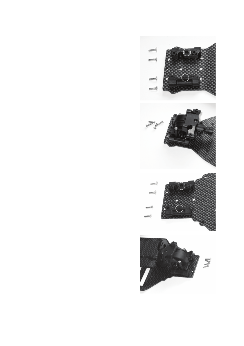
f) Mounting differentials on the chassis
Screw the two suspension arm holders into the front part of the chassis
plate. To do so use 4 counter-sunk self-tapping screws (thread length
8 mm).
On the suspension arm holders there is an "A" and "B" labelling (see
the circular mark in the figure on the right).
Ensure the correct orientation when fastening the screws; check the
correct position; the holes in the chassis plate for the attachment of
the differential must be left open and not be covered.
Attach the front differential with 4 counter-sunk self-tapping screws
(thread length 10mm).
B
A
Carry out the mounting of the rear suspension arm holders as with
those at the front.
Before you screw the rear differential tight, place the cardan shaft
between the two differentials.
Only then may you attach the rear differential to the chassis with 4
counter-sunk self-tapping screws (thread length 10mm).
If necessary adjust the motor on the motor attachment so that the
differential can be inserted.
Now set the distance between the motor pinion and main cog, see
chapter 7. e).
B
A
55
Page 56

g) Steering
C7
SR2
C4
C2
SR1
SR2
C6
C5
C3
C1
56
Page 57

Mount the two holders for the steering lever and the
servo saver as in the figure on the previous page.
The one long servo rod "LA2" will later be mounted
between the steering rod and the servo arm.
The counter-sunk screws "S6" (M3x6mm) are then
used to screw the preconstructed holders "C1" to
the chassis.
The "S4" screws (M3x10mm) serve for the mounting
of the servo rods "LA1" and "LA2".
The "S5" screws (flat-head M3x10mm) serve for the
mounting of the plastic rod "VS1" to the steering rods
("C4" and "C5").
The servo saver (the component with the spring)
serves later in protecting the servo from damage
caused by external forces affecting the steering.
S4 (M3x10mm)
S5 (M3x10mm)
S6
(M3x6mm)
C1
SR2
C2
VS1
LA2
SR1
C1 C3
C7
SR2
LA1
C6
C5
C4
57
Page 58

h) Front axle: Shock tower, suspension arms, shock absorbers
Check whether the bearing "K1" is sitting correctly on the axle stub
and insert the floating axles (D) into the axle stubs. Insert the swing
shaft (E) between the differential and the floating axle.
The front shock tower is attached to the differential with 2 self-tapping
screws (A) (thread length 10mm). Then each of the two suspension
arms are mounted each with two bolts (B and C) as shown in the
figure (the long bolt is for the bottom suspension arm and the short
one is for the upper).
Then mount the front bumper with two counter-sunk screws (8mm
thread length).
Finally you need to mount the two shock absorbers
(F). The M3x12 screw (G) attaches the shock absorber
to the shock tower, the self-tapping screw (H thread
length 15mm) is for attaching to the suspension arm.
Do not use force when tightening the screws!
Affix the shock absorbers to the left and right side of
the vehicle at the same mounting positions / holes.
Ensure also that the plastic sheath at the upper end
of the shock absorber is lying towards the shock tower,
as the shock absorber will otherwise not be able to
move freely.
F
G
H
C
D
A
B
E
58
Page 59
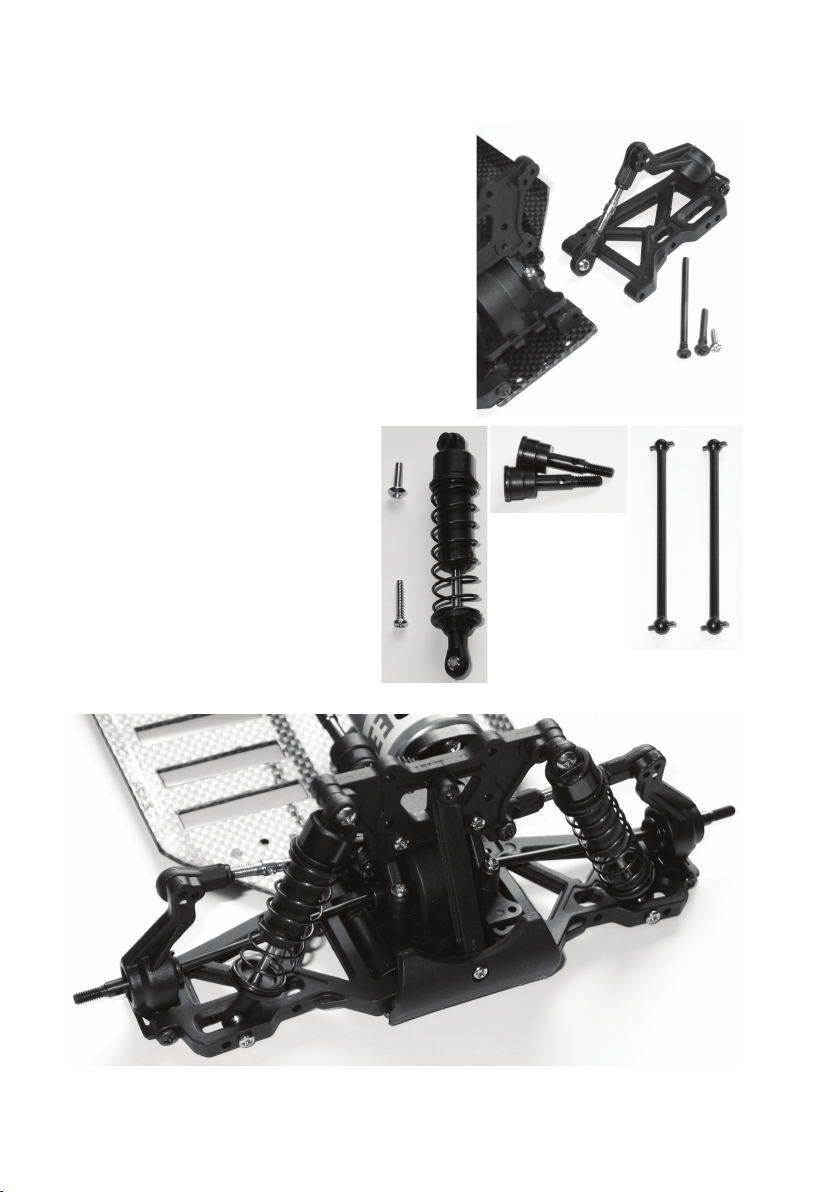
i) Rear axle: Shock tower, suspension arms, shock absorbers
Check whether the bearing "K1" is sitting correctly on the axle stub
and insert the floating axles (D) into the axle stubs. Insert the swing
shaft (E) between the differential and the floating axle.
The rear shock tower is attached to the differential with 2 self-tapping
screws (A) (thread length 10mm). Then each of the two suspension
arms are mounted each with two bolts (B and C) as shown in the
figure (the long bolt is for the bottom suspension arm and the short
one is for the upper).
Then mount the rear front bumper with two counter-sunk screws (8mm
thread length). In addition you need to insert a reinforcing strip between
the bumper and the shock tower with 2 self-tapping screws (thread
length 10mm).
Finally you need to mount the two shock absorbers
(F). The M3x12 screw (G) attaches the shock absorber
to the shock tower, the self-tapping screw (H thread
length 15mm) is for attaching to the suspension arm.
Do not use force when tightening the screws!
Affix the shock absorbers to the left and right side of
the vehicle at the same mounting positions / holes.
Ensure also that the plastic sheath at the upper end
of the shock absorber is lying towards the shock tower,
as the shock absorber will otherwise not be able to
move freely.
F
G
H
D
B
C
A
E
59
Page 60

j) Steering servo
SE1
The steering servo (not part of the delivery, must be ordered separately) is
attached to the chassis using the two holding brackets "SE1". The adjustable
servo rod is to be mounted between the steering rod and the servo arm with
2 M3x 10mm screws.
The later adjustment of the servo arm to the servo axle and the setting of the
servo rod is to be carried out once the vehicle is complete (after installation
of the drive control unit and a remote control). This may require the servo to
be removed again in order for the servo arm to be adjusted to the servo axle.
The holding brackets with the servo arm are attached to the chassis with 4
counter-sunk self-tapping screws (thread length 8mm).
60
Page 61

k) Drive covering, chassis bridge
S1
S4
M3 x 10mm
EH1
S2
First mount the two short retaining pins "HA1" and the long
retaining pins "HA2" on the chassis, use counter-sunk selftapping screws with a thread length of 8mm.
Afterwards, the chassis bridge "CB1" can be attached.
The two "S4" screws (M3x10mm) are screwed to the
attachments for the steering lever.
The two "S7" screws (M3x15mm) are screwed through the
chassis bridge and the gear cover to the motor attachment.
Two long self-tapping screws "S2" (thread length 15mm) are
to be attached to the differential housings front and rear.
Finally, 5 additional self-tapping screws "S1" (thread length
10mm) are screwed to the retaining pins and the receiver
mount "EH1" thus completing the mounting of the chassis
bridge.
The "AN1" attachment for the antenna tube is inserted between
"HA2" and "CB1".
HA2
CB1
HA1
S7
M3 x 15mm
S2
S1
S1
GA1
AN1
HA1
HA1
HA2
EH1
61
Page 62
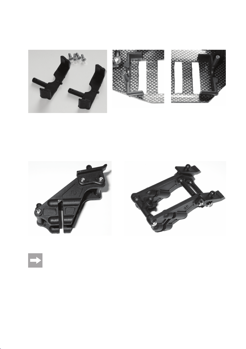
l) Rechargeable battery bracket
Attach the battery brackets left and right of the 6 opening in the chassis. To do so use 2 counter-sunk self-tapping
screws for each (thread length 8 mm).
m) Rear spoiler mount
There is a pin for mounting the car body on the rear spoiler mount. Attach the two sides together as shown in the figure.
The left side part is marled with an "L" and the right with "R". Use a total of 6 self-tapping screws (thread length 12mm).
The completed mount is placed over the rear shock tower and then affixed with four long self-tapping screws (thread
length 15mm).
Fix the rear spoiler supplied to the spoiler mount using two split pins.
The rear spoiler angle can be adjusted through several settings using the mechanism integrated into the
mount.
62
Page 63

n) Front body mount
The front body mount requires a small plastic part (see the
circle in the figure on the right) to be attached to the shock
tower with a self-tapping screw. Later, the car body will be
attached to this with a split pin.
o) Hubs and wheels
Place the remaining "K2" bearings onto all axle stubs if
you have not done so already. Then slot the metal pin into
the opening on the wheel axle. The plastic nut needs to be
placed over this pin.
Ensure that the nut is correctly positioned - the slotted side
must be slid over the metal pin.
Finally push a wheel onto each axle and screw on the stop
nuts. Do not fail to observe the correct orientation of the
stop nuts - the rounded side should face outwards.
63
Page 64

p) Receiver and drive control unit
These components are not included in the delivery. The receiver is included with your remote control, the
drive control unit needs to be ordered separately.
The receiver is attached to the underside of the receiver bracket "EH1" with double-sided adhesive tape. In addition
it is to be affixed with cable ties inserted through the slit in the receiver bracket. This ensures that the receiver will not
come loose.
The drive control is attached to the upper side of the chassis bridge "CB1" with double-sided adhesive tape. Be careful
to ensure that the car body still fits as you do this!
The drive control unit switch can also be attached with double-sided adhesive tape, e.g. to the steering servo.
Pass the antenna cable on the receiver through the "AN1" holder and then through the antenna tube. Insert the
antenna tube into the "AN1" holder. Affix the antenna cable at the upper end of the antenna tube with a rubber cap.
When laying the antenna cable, ensure that it doesn't enter the cardan shaft or other rotating parts. Never shorten the
antenna cable!
Connect the steering servo and the drive control unit with the receiver. Consult the operating instructions for the
remote control to determine which connections the steering servo and drive control unit need to be attached.
64
Page 65

8. Setting the undercarriage
Once it has been constructed the undercarriage needs to be adjusted/set.
The explanations of the correlation between chassis set-up settings and driving behaviour are, however, very complex
and would go beyond the scope of these instructions. For this reason, we can only show the setting options provided.
For further information we have to refer you to appropriate specialist magazines as well as comprehensive reference
books on this subject.
a) Setting the camber
The camber is the inclination of the wheel level as viewed from the front (vertical).
Negative camber Positive camber
(wheel upper edges point inwards) (wheel upper edges point outwards)
The setting of the wheels in the two figures is shown in an exaggerated in order to show you the difference
between negative and positive camber. Such an extreme setting should not be made on the model vehicle!
A negative camber (wheel upper edges point inward) on the front wheels increases the cornering force of the wheel
when driving in bends, the steering reacts more directly, the steering force required is reduced. At the same time the
wheel is pushed onto the axle leg in the direction of the axle. This disables axial bearing clearance, the overall handling
is improved.
A negative camber on the rear wheels reduces the tendency of the rear of the vehicle to swerve/slide out on bends.
A positive camber, on the other hand, reduces the cornering forces on the tyres and should not be used.
65
Page 66
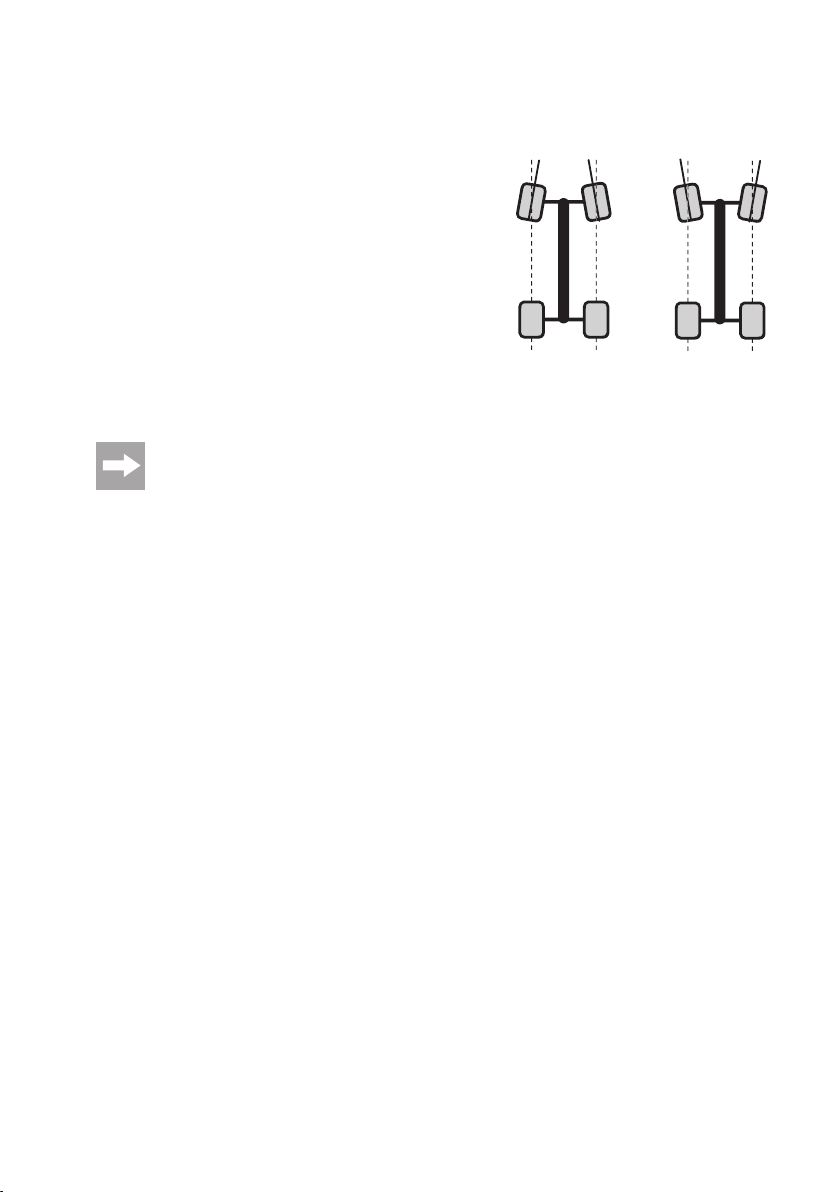
b) Setting the alignment
This alignment (toe-in = figure "a", toe-out = figure "b") designates the
position of the wheel level to the driving direction.
While you are driving, the tyres are pushed apart in the front because
of rolling friction and this is why they are no longer precisely parallel to
the direction being driven. To balance this out, the tyres of the stationary
vehicle can be adjusted in a way so that they point slightly inwards.
This toe-in improves the lateral cornering of the tire and therewith gives
a more direct response to the steering.
If a milder response to steering is desired, this can be achieved
accordingly by adjusting a toe-out, i.e. the wheels of the stationary
vehicle point outward at the front. An alignment angle of 0° on the front
axle ensures the best driveability on almost any ground.
An alignment angle of more than 3° toe-in (a) or toe-out (b) leads to
handling problems and reduces speed.
The toe-in of the front wheels should not exceed 4°; the figures on the figure show a very excessive setting
which only serves to show the difference between toe-in and toe-out.
a
b
¦¦
66
Page 67

c) Front axle
A
C
F
D
B
• The shock absorbers can be mounted on the top (A) and bottom (B) attachment points at different positions.
• The absorption of the shock absorbers themselves can - for example - be adjusted (C) by inserting clips and the
suspension travel can be reduced.
• The wheel camber can be changed by changing the setting on the upper (D) or lower (E) suspension arm.
A small hex/Allen key is required to turn the ball-head screw on the upper and lower suspension arm. Take care
when doing so to ensure that at least about 2/3 of the thread length of the ball-head screw remains in the suspension
arm and that the swing shaft does not become loose (ball-head screw is turned too far out) and that it is not too tight
(ball-head screws turned too far in).
• The steering linkages (F) for the linkage rods allows you to set a positive or negative toe.
In addition to the above described adjustment options, you could use different shock absorbers or springs,
and different shock absorber oils with a different viscosity that will influence the behaviour of the suspension.
E
67
Page 68

d) Rear axle
A
C
D
B
• The shock absorbers can be mounted on the top (A) and bottom (B) attachment points at different positions.
• The absorption of the shock absorbers themselves can be adjusted (C) by inserting clips and the suspension travel
can be reduced.
• The camber can be adjusted by adjusting the upper suspension arm using a threaded rod with a hole (D).
In addition to the above described adjustment options, you could use different shock absorbers or springs,
and different shock absorber oils with a different viscosity that will influence the behaviour of the suspension.
68
Page 69

9. Recharging Battery Pack
Please note:
No rechargeable battery pack is included with the vehicle, this must be ordered separately.
The rechargeable battery pack is empty on delivery and must be charged.
Before the rechargeable battery pack delivers its maximum power, several complete discharge and charge
cycles are necessary.
Always use the NiCD rechargeable battery pack until it is empty if possible, as recharging a "half-full"
rechargeable battery pack repeatedly can cause a so called memory effect. This means that the rechargeable
battery pack loses its capacity, it no longer releases all of its saved energy, drive time is decreased.
This effect is much slighter in rechargeable batteries with NiMH technology, and recharging partially
discharged rechargeable batteries is less problematic.
High-quality rechargeable batteries not only have a higher capacity, which allows you to drive your model
vehicle much longer and also delivers a higher output voltage for extreme situations. This gives the engine
more power and results in better acceleration and higher speed.
If you are using several rechargeable battery packs or rechargeable batteries, purchasing a high-quality
charger may be worthwhile. They are normally also suitably for fast charging of rechargeable batteries.
Rechargeable batteries heat up during charging/discharging (driving the vehicle). Wait until the rechargeable
battery has reached room temperature before charging it. The same applies after the charging procedure.
Do not use the rechargeable battery in the vehicle until it has cooled down sufficiently after the charge
process.
69
Page 70

10. Operation
a) Removing the car body
The car body is secured with holding brackets which must be slid out from the retaining pins. The car body can then be
taken off.
b) Placing the rechargeable battery pack in the vehicle
Note!
The rechargeable battery pack must not be connected to the drive control unit yet!
On one side of the vehicle there is a battery pack compartment. The attachment of the rechargeable battery pack is
carried out using a plastic brace which is secured using two attachment clips.
Insert the rechargeable battery pack in a manner that the connection cable cannot be caught in the steering mechanism
or the drive.
c) Inserting batteries/rechargeable batteries into the remote control
(transmitter)
If you have not done so already, insert the rechargeable battery/batteries into the remote control (transmitter). Please
also note the operating instructions of your remote control.
d) Switching on the remote control (transmitter)
Always turn on the remote control (transmitter) before connecting the rechargeable battery packs to the drive control
unit. Check the status of the inserted battery.
e) Connecting the rechargeable battery pack to the drive control unit
Before connecting a rechargeable battery pack to the drive control unit, switch on the remote control (transmitter) (see
chapter 9. c) and 9. d).
To prevent a sudden movement of the drive and an uncontrolled movement of the model (e.g. if the trim for
the drive is wrongly adjusted), place the vehicle on a suitable support (such as a start box), so that the
wheels can turn freely.
Switch off your drive control unit.
Then connect the rechargeable battery pack to the drive control unit.
70
Page 71

f) Activating the drive control unit
First switch on the remote control (transmitter), see chapter 9. c) and 9. d), if you have not already done so!
Only now should you turn on the drive control unit.
You may need to programme the drive control unit to specify the neutral setting, and full acceleration
forwards and backwards.
g) Checking the driving and steering function
Before every trip you should check that the remote control (transmitter) settings are correct and whether the vehicle
reacts appropriately to control commands.
As described in Chapter 9. e), the vehicle should be placed on a suitable base (e.g. a start box) or similar
stand to allow the drive to turn freely.
• Set the trimming on your remote control such that the drive does not move when the gas/brake lever is in the neutral
setting.
• Set the steering trim so that the wheels are aligned forward when the dial on your remote control is in the middle
setting.
If the trim range is not sufficient for correct setting, the servo lever on the servo axle needs to be adjusted or the servo
rod "LA2" needs to be turned (see chapter 7. g).
• Make sure that steering reacts appropriately to the remote control. If the wheels react in the opposite direction, e.g.
when using a pistol-grip remote control (dial to the left, wheel to the right), then activate the reverse function.
The same applies for forward/reverse: If the drive control unit has a braking function, it may be necessary to activate
not only the reverse function on the remote control but also to interchange the two motor cables (between the motor
and the drive control unit).
Please also note the operating instructions of your remote control.
h) Attaching and fastening the car body
Guide the tube of the antenna from underneath the car body through the hole intended for that purpose. If no opening
is present, use an appropriate tool to make the hole in the right place.
Now put the car body on the holders and fasten the vehicle panelling with the holding brackets removed at the start.
Your car is now ready for its first test run!
71
Page 72

i) Ending use
To stop driving, proceed as follows:
• Let the vehicle roll to a halt.
• Once the vehicle comes to a standstill, remove the body and turn the vehicle off (e.g. drive control unit switch to the
"OFF" position).
Make sure not to touch the wheels or the drive, and do not move, in any case, the lever for the drive
function on the remote control (transmitter)!
• Disconnect the rechargeable battery pack from the drive control unit. Disconnect the plug-in connection completely.
• Only then may you turn off the remote control (transmitter).
Note!
The motor, drive control unit and rechargeable battery pack become very hot during operation! Do not
touch these parts immediately after operation. Danger of burns!
Stop driving immediately if the vehicle shows unusual responses to the remote commands or if the vehicle
does not respond at all.
This behaviour could be caused by a weak vehicle battery, weak batteries/rechargeable batteries in the
remote control or by too great a distance between vehicle and remote control.
The antenna of the remote control not being fully extended, disturbances on the radio channel used (e.g.
other models, radio transmissions through other devices) or adverse transmission/reception conditions
could also be causes of unusual responses by the vehicle.
j) Carrying the vehicle
Radio interference, unintentional use of the remote control or a transmitter using the same channel can lead to
unpredictable responses by the vehicle.
72
Thus it is imperative to ensure that you do not reach into the drive, when the vehicle is being placed in its
start position or if it is to be lifted off the ground.
Page 73

11. Cleaning and Maintenance
a) General information
Prior to cleaning or servicing, turn the vehicle off and completely separate the rechargeable battery pack
from the drive control unit. If you drive the vehicle beforehand, leave all parts (e.g. engine, drive control,
etc.) to cool down completely first.
Clean the whole vehicle of dust and dirt after driving, e.g. with a long-haired clean brush and a vacuum cleaner.
Compressed air aerosols can also be helpful.
Do not use cleaning aerosols or conventional household cleaners. This may damage the electronics and
lead to discolouration on the plastic parts or the body.
A soft cloth, slightly dampened can be used to wipe the car body. Do not rub too firmly to avoid scratch marks.
Motor vibrations and shocks during driving can loosen parts and screw fittings. This is why you should check the
tightness of wheel nuts and all screw fittings before or after every use. The same applies for other parts of the vehicle.
Nonetheless, do not use force when tightening the screws! Screws which are inserted into plastic parts will
be overtightened or "threaded" and will no longer sit tightly.
If, for example, the wheel nuts are excessively tightened, the bearings/wheel bearings will jam, this increases
the power usage of the electric motor and leads to overheating of the drive control unit and electric motor
as well as a reduction in vehicle speed.
Check if the tyres sit correctly on the wheel rims and if the adhesives have loosened.
Only the differential requires lubrication/greasing, as already described in the construction instructions. The other
parts of the vehicle should only be cleaned of dust and dirt, greasing will not be of use - in fact dust and dirt build up
very quickly on these parts which leads to increased wear.
If worn-out or defective vehicle parts must be replaced, use original spare parts only.
Make sure that no cables are pinched or caught and that cable cannot enter or become entangled in moving parts or
the drive.
Check the model for damage before each use. If you notice any damage, the car must not be used anymore and has
to be taken out of operation.
73
Page 74

b) Adjusting the tooth profile clearance
The tooth profile clearance must be correctly set before you first use the vehicle.
To do so, loosen the two fastening screws on the electric motor so that you can move the motor with slight pressure in
the direction of the main pinion (only loosen the screws slightly, don't fully remove them!). The cog/pinion cover may
need to be removed prior to this.
The motor pinion and the main drive gear now engage without clearance.
Insert a thin paper strip between the motor pinion and the main pinion and rotate the main pinion manually in such a
way that the paper strip is pulled in between both pinions.
The paper positioned between the cogs lifts the electric motor as far as is necessary to ensure the correct clearance.
Now tighten the attachment screws of the motor again.
When you turn back the main drive gear afterwards so that the paper strip can be taken out again, the correct clearance
should be apparent between the cogs.
Ideally the pinion should be as close as possible to the main cog without the teeth touching.
If the cogs (pinion and main cog) are too far apart, then even a few seconds driving will destroy the main
cog's teeth - this voids your guarantee!
If the pinion is pushing too hard against the main cog (gears run with no clearance) then there will be a loss
of performance along with increased energy use and a premature use of the main cog.
Check after each use that the tooth clearance is correct; it is possible that the motor has come loose or been moved
due to vibrations.
c) Changing the crystal
There is not allowed to be any other transmitter/models with the same frequency in the range of the transmitter, as the
transmitters will interfere with each other. As a result, the models no longer respond correctly to the transmitter commands.
If there are other model vehicles in your range, talk to the other operators about the frequencies they use.
Only use suitable accessory crystals for the transmitter and the receiver.
Before changing a crystal, first turn off the vehicle and then the remote control (transmitter).
Transmitter crystals are marked with "T" or "TX", receiver crystals with "R" or "RX". Don't mix up the crystals, as
otherwise the model won't function correctly.
74
Page 75
12. Disposal
a) General information
Electronic devices must not be disposed of in the domestic waste.
Please dispose of the device, when it is no longer of use, according to the current statutory requirements.
b) Batteries and rechargeable batteries
You as end user are under legal obligation (Battery Regulation) to take back all used batteries and rechargeable
batteries. Disposing of them in the domestic waste is not permitted!
Batteries/rechargeable batteries containing harmful substances are marked with the following symbols,
which point out that disposal in the domestic waste is prohibited. The designations for the relevant heavy
You thus fulfil your statutory obligations and contribute to the protection of the environment.
metals are: Cd=cadmium, Hg=mercury, Pb=lead (name on battery/rechargeable battery, e.g. under the
trash icons on the left).
You can hand in your used batteries/rechargeable batteries at the official collection points of your community
at no cost, at our outlets or everywhere where batteries/rechargeable batteries are sold.
75
Page 76

13. Troubleshooting
Even though the model and the remote control system were built with the latest available technology, there can still be
malfunctions or faults. This is why we would like to show you how to remove some possible faults.
Problem
The model doesn’t respond
Vehicle doesn’t stop when you let
go of the operating lever for the drive
function
The vehicle doesn’t drive in a
straight line correctly
Steering or driving movements
opposite to movement of steering
dial and throttle lever
Vehicle becomes slower or the
steering servo only shows slight
reactions.
Unpredictable vehicle reactions;
drive or servos start without reason,
steering does not function properly.
Remedy
• Check the vehicle's rechargeable battery pack
• Check the rechargeable batteries/batteries in the transmitter
• Check the rechargeable battery pack connection.
• Check the on/off switch of the vehicle and the transmitter.
• Check marking on crystals (same frequency or transmitter/receiver crystal
correctly inserted?).
• Carry out crystal change to a different channel.
• Adjust the neutral position for the drive function via the trimmer on the
transmitter.
• Adjust the steering function correctly with the trimmer on the transmitter.
• Check the steering linkage.
• Check the clearance in the steering/wheel suspension and, if necessary,
replace the defect/worn out parts.
• Check servo reverse function on the transmitter, if necessary, modify
the setting.
• Check the vehicle's rechargeable battery pack
• Completely extend the transmitter antenna.
• Unwrap the receiver's antenna and install it properly (in the vertically
mounted antenna tube).
• Check the rechargeable batteries/batteries in the transmitter
• Check the vehicle's rechargeable battery pack
• Check marking on crystals (same frequency or transmitter/receiver crystal
correctly inserted?).
• Carry out crystal change to a different channel.
• Distance between vehicle and transmitter is too small or too large.
76
Page 77

14. Technical Data
Scale: ........................................................1:10
Drive: ........................................................ Electric motor type 540
Four-wheel drive via cardan shaft
Ball bearing drive
Differential in front and rear axle
Suspension: ..............................................Independent suspension, with 1 shock-absorber per wheel
Dimensions (L x W x H): ...........................approx. 400 x 235 x 167mm
Tyre dimensions (W x Ø):......................... Ca. 34 x 87mm
Alignment: .................................................approx. 205/200mm (front/back)
Wheel base:.............................................. Approx. 270mm
Weight:...................................................... Depending on fittings approx. 1300-1500g (without battery pack)
Required/recommended accessories (not included in delivery):
Drive control unit:...................................... Electronic drive control unit (forwards/reverse/brake) with BEC
Steering servo: ......................................... Standard or high speed servo 40x20mm
Rechargeable drive battery: .....................NiMH racing pack, 6 SubC-cells, 7.2V
Remote control system:............................ 2 channels
77
Page 78

1. Introduction ....................................................................................................................................................... 79
2. Utilisation conforme .......................................................................................................................................... 80
3. Contenu de la livraison ..................................................................................................................................... 80
4. Explication des symboles ................................................................................................................................. 80
5. Consignes de sécurité ...................................................................................................................................... 81
6. Indications afférentes aux piles et accumulateurs ........................................................................................... 84
7. Montage ............................................................................................................................................................ 85
8. Ajuster le châssis ............................................................................................................................................ 103
9. Recharger le pack d'accumulateurs ............................................................................................................... 107
10. Mise en service ............................................................................................................................................... 108
Table des matières
a) Généralités ..................................................................................................................................................81
b) Montage ...................................................................................................................................................... 81
c) Fonctionnement .......................................................................................................................................... 82
a) Différentiel avant ......................................................................................................................................... 85
b) Différentiel arrière ....................................................................................................................................... 87
c) Bras oscillant transversal avant .................................................................................................................. 90
d) Bras oscillant transversal arrière ................................................................................................................ 91
e) Support moteur et moteur ...........................................................................................................................92
f) Montage des différentiels au châssis ......................................................................................................... 93
g) Direction ...................................................................................................................................................... 94
h) Essieu avant : pont d'amortisseurs, bras oscillant transversal, amortisseurs ............................................96
i) Essieu arrière : pont d'amortisseurs, bras oscillant transversal, amortisseurs .......................................... 97
j) Servo de direction ....................................................................................................................................... 98
k) Revêtement de la boîte de vitesse , pont du châssis ................................................................................. 99
l) Support d'accumulateurs ..........................................................................................................................100
m) Support du déporteur ................................................................................................................................100
n) Support de carrosserie avant ................................................................................................................... 101
o) Entraineur de roue et roues ......................................................................................................................101
p) Récepteur et régulateur de vitesse .......................................................................................................... 102
a) Réglage du déport de roue .......................................................................................................................103
b) Réglage de la voie .................................................................................................................................... 104
c) Essieu avant ............................................................................................................................................. 105
d) Essieu arrière ............................................................................................................................................ 106
a) Retrait de la carrosserie ............................................................................................................................108
b) Mise en place du pack d´accus dans le véhicule ..................................................................................... 108
c) Mise en place des accumulateurs/des piles dans la radiocommande (émetteur) ................................... 108
d) Mise en marche de la radiocommande (émetteur) .................................................................................. 108
e) Raccordement du pack d´accumulateurs au régulateur de vitesse .........................................................108
f) Activation du régulateur de vitesse ..........................................................................................................109
Page
78
Page 79

Page
g) Contrôle des fonctions d'entraînement et de commande ........................................................................ 109
h) Mise en place et fixation de la carrosserie ............................................................................................... 109
i) Arrêt de la course ..................................................................................................................................... 110
j) Transport du véhicule ............................................................................................................................... 110
11. Nettoyage et maintenance .............................................................................................................................. 111
a) Généralités ................................................................................................................................................ 111
b) Réglage du jeu de battement ................................................................................................................... 112
c) Remplacement du quartz ......................................................................................................................... 112
12. Elimination....................................................................................................................................................... 113
a) Généralités ................................................................................................................................................ 113
b) Piles et accumulateurs .............................................................................................................................. 113
13. Dépannage ..................................................................................................................................................... 114
14. Caractéristiques techniques ........................................................................................................................... 115
1. Introduction
Chère cliente, cher client,
Nous vous remercions de l’achat du présent produit.
Ce produit répond aux exigences légales nationales et européennes.
Le présent mode d'emploi fait partie intégrante du produit. Sie enthält wichtige Hinweise zur Inbetriebnahme und Handhabung. Il faut respecter ces instructions, même si ce produit est transmis à
une tierce personne.
Conservez le présent mode d'emploi afin de pouvoir le consulter à tout moment!
Tous les noms d’entreprises et appellations de produits contenus dans ce mode d’emploi sont des marques déposées
des propriétaires correspondants. Tous droits réservés.
Pour toutes vos questions techniques, veuillez vous adresser au numéro suivant :
Pour toutes vos questions techniques, veuillez vous adresser à :
Tél. : 0892 897 777
Fax : 0892 896 002
e-mail : support@conrad.fr
Du lundi au vendredi de 8h00 à 18h00, le samedi de 8h00 à 12h00
Tél. : 0848/80 12 88
Fax : 0848/80 12 89
e-mail : support@conrad.ch
Du lundi au vendredi de 8h00 à 12h00 et de 13h00 à 17h00
79
Page 80

2. Utilisation conforme
Le produit est un kit pour modèle réduit de véhicule à quatre roues motrices.
Les accessoires indispensables au fonctionnement (non compris dans la livraison sont : radiocommande (émetteur/
récepteur), servo de direction, régulateur de vitesse, accumulateur pour moteur (racing pack), piles/accumulateurs
pour la radiocommande, chargeur.
Ce produit n’est pas un jouet et ne convient pas aux enfants de moins de 14 ans.
Tenez compte de toutes les consignes de sécurité du présent mode d’emploi. Il contient des
informations importantes relatives à l'utilisation du produit.
Les informations données dans cette notice se réfèrent en partie au kit et en partie au véhicule
assemblé qui est rendu prêt à être mis en service par le montage de modules supplémentaires
(émetteur/réceteur, régulateur de vitesse, servo de direction, accumulateur pour moteur, tous non
compris dans la livraison !).
3. Contenu de la livraison
• Kit d'assemblage pour véhicule
• Moteur électrique type 540
• Notice d'utilisation
Vous trouverez la liste des pièces détachées sur notre site Web www.conrad.com dans la section
téléchargement du produit respectif.
Vous pouvez aussi demander cette liste par téléphone, vous trouverez les coordonnées de contact au
début de cette notice d'utilisation au chapitre «Introduction».
4. Explication des symboles
Un point d'exclamation placé dans un triangle attire l'attention sur des dangers particuliers lors du maniement,
du fonctionnement et de l'utilisation.
Le symbole de la «flèche» précède des conseils et consignes d´utilisation particuliers.
80
Page 81

5. Consignes de sécurité
Tout dommage résultant d'un non-respect du présent mode d'emploi entraîne l'annulation de la
garantie ! Nous déclinons toute responsabilité pour d’éventuels dommages consécutifs !
Nous déclinons toute responsabilité pour d'éventuels dommages matériels ou corporels dus à un
maniement incorrect ou à la non-observation des consignes de sécurité ! De tels cas entraîne
l’annulation de la garantie.
La garantie ne couvre pas les traces d´usure normales causées par la mise en service (par ex.
pneus lisses) et les dommages causés par un accident (par ex. levier triangulaire cassé, carrosserie
rayée ou endommagée etc.).
Chère cliente, cher client, ces mesures de sécurité servent non seulement à la protection du produit mais
également à assurer votre propre sécurité et celle d’autres personnes. Pour cette raison, veuillez lire ce
chapitre attentivement avant la mise en service du produit !
a) Généralités
Attention, remarque importante !
L'utilisation du modèle réduit pourrait entraîner des dommages matériels ou corporels. Veillez par
conséquent à assurer suffisamment votre modèle réduit, par ex. dans le cadre d'une assurance de
responsabilité civile. Si vous possédez déjà une telle assurance, veuillez alors vous informer auprès de
votre assurance avant toute mise en service du modèle réduit si cette dernière lest couverte.
• Pour des raisons de sécurité et d’homologation (CE), il est interdit de modifier et/ou de transformer le produit soi-
même.
• Ce produit n’est pas un jouet et ne convient pas aux enfants de moins de 14 ans.
• Il faut impérativement veiller à ce que l’appareil ne soit ni mouillé ni humide.
• Ne laissez pas traîner le matériel d’emballage. Il pourrait devenir un jouet dangereux pour les enfants.
• Si vous avez des questions auxquelles le mode d'emploi n'a pus répondre, veuillez nous contacter (voir chapitre 1
pour les coordonnées) ou consultez un autre spécialiste.
Il faut apprendre à utiliser et à commander les modèles réduits de véhicule radiopilotés ! Si vous n’avez
jamais piloté un tel véhicule, veuillez alors être particulièrement prudent et prenez le temps de vous
familiariser aux réactions du véhicule aux commandes de la télécommande. Soyez patient !
b) Assemblage
• Lors de l'assemblage du véhicule les arêtes vives, les pièces pointues et une manipulation non conforme avec les
outils représentent un risque de blessures.
• Un mauvais assemblage peut entraîner l'endommagement des pièces du véhicule et détériore ultérieurement la
puissance du moteur. Procédez alors avec le plus grand soin pour l'assemblage.
81
Page 82

• Assemblez le véhicule uniquement sur une surface suffisamment grande, plane et stable. Protégez la surface d'une
table de travail par ex. à l'aide d'un support épais approprié contre toute rayure.
• Ne forcez pas lors de l'assemblage des pièces ; ne forcez jamais les vis ! Veillez cependant à ce que les vis, écrous
etc. soient correctement fixés.
• Utilisez des outils appropriés et en parfait état pour l'assemblage.
• Prenez votre temps !
• Si vous n'avez pas encore assemblé un tel véhicule, cherchez l'aide de par ex. un collègue modéliste qui a plus de
connaissances. Notamment au début d'une «carrière en tant que modéliste» quelques rares mais bons conseils et
astuces d'un expert peuvent vous dépanner dans de nombreuses cas.
c) Fonctionnement
• Assurez-vous avant chaque mise en service qu'aucun autre modèle réduit fonctionnant sur la même fréquence ne
se trouve dans la portée de la radiocommande. Ceci fait perdre le contrôle du modèle radiopiloté ! Utilisez toujours
différentes fréquences pour chacun des modèles.
• Avec chaque mise en service, contrôlez le réglage du compensateur pour la marche avant/arrière, de même que
pour la direction, et si nécessaire, modifiez le réglage.
Pour cette raison, veillez, lors de la mise en service (mise en marche de la télécommande et du véhicule), à ce que
les roues du modèle ne soient pas encore placées sur le sol ; placez le modèle sur un support approprié de sorte à
ce que les roues puissent tourner librement (ne pas toucher l'entraînement !).
Réglez ensuite le compensateur, de sorte qu'une fois que le levier pour la marche avant/arrière soit complètement
relâché (position neutre), le moteur ne tourne plus et que la direction soit alignée tout droit (un réglage de précision
pour la conduite en ligne droite peut être effectué plus tard pendant la course).
• Lors de la mise en service, allumez toujours d'abord la radiocommande (émetteur). Ce n'est qu'après cela que le
pack d'accumulateurs du véhicule peut être connecté au régulateur de vitesse/récepteur et que le modèle réduit
peut être mis allumé. Autrement, des réactions inattendues du régulateur de vitesse/récepteur et de par là du
modèle réduit peuvent survenir!
Ressortez complètement l'antenne télescopique de la radiocommande. Lorsque vous utilisez une radiocommande
2.4GHz, orientez l'antenne verticalement (si votre radiocommande est munie d'une antenne repliable).
• Une utilisation non conforme peut provoquer de graves dommages corporels ou matériels ! Veillez à toujours maintenir
un contact visuel direct de votre modèle réduit lors du pilotage. Pour cette raison, ne le mettez pas en service la nuit.
• Ne l'utilisez que si vos réflexes sont absolument non restreints. La fatigue, l'influence de l'alcool, des médicaments
peut entraîner de mauvais réflexes, exactement comme lors du maniement d'un véritable véhicule.
• Veuillez tenir compte du fait qu'il n'est pas autorisé d'utiliser ce modèle réduit dans des rues ou voies publiques. Ne
l’utilisez que dans des endroits privés ou des endroits prévus pour.
• Ne le dirigez pas vers des animaux ou des personnes!
• Ne l’utilisez pas en temps de pluie, sur une pelouse mouillée, dans de l’eau, de la boue ou de la neige. Le modèle
réduit n'est pas résistant à l'eau et n'est pas étanche.
• Evitez également son utilisation par des températures extérieures très basses. Par temps froids, le plastique de la
carrosserie et des pièces du train pourrait perdre de son élasticité et même de petits accidents pourraient endommager
le modèle réduit.
82
Page 83

• Ne l'utilisez pas par temps orageux, sous des lignes hautes tensions ou à proximité de pylônes d'antennes.
• Évitez de prendre des risques lors du fonctionnement du produit ! Votre sécurité personnelle et celle de votre
entourage dépendent exclusivement de votre comportement responsable lors de la manipulation du modèle réduit.
• Laissez toujours la télécommande (émetteur) allumé, tant que le modèle réduit est en service. Pour arrêter le
véhicule, éteignez toujours d'abord le véhicule et déconnectez le pack d'accumulateurs du régulateur de vitesse/
récepteur. Ce n'est qu'après cela que vous devez éteindre la télécommande.
• Contrôlez, avant l’utilisation du modèle réduit, s’il réagit aux commandes de la télécommande ainsi que prévu.
• Si les piles (ou accumulateurs) dans la télécommande sont faibles, la portée diminue. Si l'accu du moteur est faible,
le véhicule devient plus lent ou ne réagit plus correctement aux commandes de la télécommande.
Dans ce cas, arrêtez immédiatement le modèle réduit. Remplacez ensuite les piles/accumulateurs de la
radiocommande par des neuves ou rechargez les accumulateurs dans le véhicule ou la radiocommande.
• Le moteur et l'entraînement de même que le régulateur de vitesse et le pack d'accumulateurs du modèle s'échauffent
lors du fonctionnement. Respectez une pause d´au moins 5 à 10 minutes avant de remplacer les accumulateurs ou
de les recharger.
Ne jamais toucher le moteur,le régulateur de vitesse et l'accumulateur. Attendez qu'ils se soient refroidis.
Risques de brûlures !
83
Page 84

6. Conseils relatifs aux piles et aux accumulateurs
• Les piles et les accumulateurs ne doivent pas être laissés à portée des enfants.
• Ne laissez pas traîner des piles ou accumulateurs. Ils risquent d´être avalés par un enfant ou un animal domestique.
Dans ce cas, consultez immédiatement un médecin !
• Faites attention de ne pas court-circuiter les piles/accumulateurs, ni de les jeter dans le feu, ni de les ouvrir. Risque
d'explosion !
• Les accumulateurs ou les piles endommagés ou qui fuient peuvent entraîner des brûlures en cas de contact avec la
peau. Veuillez donc utiliser des gants de protection appropriés.
• Les piles normales (non rechargeables) ne doivent pas être rechargées. Danger d´incendie et d´explosion ! Ne
rechargez que les accumulateurs prévus à cet effet ; n'utilisez que des chargeurs d'accumulateurs appropriés.
• Faites attention quand vous insérez les piles ou le pack d'accumulateurs dans le compartiment à piles à bien
respecter la polarité correcte (positive/+ et négative/-).
• Si vous n'utilisez pas l'appareil pour une longue durée (par ex. lors d'un stockage) retirez les piles ou les accumulateurs
de l'émetteur car elles risquent de corroder et d'endommager ainsi l'appareil. Déconnectez l'accumulateur pour
moteur du régulateur de vitesse.
Rechargez les accumulateurs environ tous les 3 mois, autrement, l’autodécharge provoque une décharge dite
complète, ce qui rend les accumulateurs inutilisables.
• Remplacez toujours le jeu entier de piles ou d'accumulateurs. Ne mélangez pas des piles/accumulateurs
complètement chargés avec des piles/accumulateurs à moitié chargés. N'utilisez que des piles ou des accumulateurs
du même type et du même fabricant.
• N'insérez jamais piles et accumulateurs en même temps ! Utilisez pour l'émetteur soit des piles soit des accumulateurs.
L'émetteur fonctionne aussi bien avec des accumulateurs qu'avec des piles.
La faible tension (piles = 1.5V, accumulateurs = 1.2V) et la faible capacité des accumulateurs cause une
diminution de la durée d'utilisation. Ceci ne joue toutefois aucun rôle étant donné que la durée de service
de l'émetteur est bien plus longue que celle de l'accumulateur d'entraînement.
Si vous souhaitez insérer des piles dans l´émetteur, nous vous recommandons d'utiliser des piles alcalines
de haute qualité.
L’utilisation d’accumulateurs peut causer une diminution de la portée.
84
Page 85

7. Montage
a) Différentiel avant
Les deux différentiels avant et arrière sont identiques sauf pour l'essieu entraîné du moteur (pour le différentiel arrière,
la roue dentée prinicpale pour l'entraînement est montée à travers le moteur électrique).
S1 (10mm)
S2 (15mm), 4x
A1
ST1
K1
SR1
A2
Z1
K2
AC1
A5
A3
K1 (Ø10 x Ø15 x 4)
K2 (Ø5 x Ø11 x 4)
K3 (Ø5 x Ø10 x 4)
Veillez à utiliser les bons roulements à billes. Le roulement à bille «K3» est un peu plus petit et s'utilise pour le
différentiel arrière.
Le composant «A4» est en fait le différentiel de bille conique, il est prémonté (la figure en haut représente l'intérieur).
A4
K1
85
Page 86

Montez en premier l'essieu entraîné comme indiqué dans la figure. Placez la roue dentée «Z1» en respectant la
bonne orientation sur l'essieu «AC1» et fixez-la par la petite bague de sûreté «SR1». Placez ensuite deux roulements
à bille «K2» (5 x 11 x 4mm) sur l'essieu et en dernier le manchon plastique «A5» (respectez la bonne orientation, le
méplat assure que l'essieu ne peut être inséré dans le manchon plastique que dans une seule position).
Fixez alors le manchon plastique «A5» par la longue tige métallique noire rainurée «ST1» sur l'essieu.
Z1
SR1
Insérez le différentiel de bille conique «A4» et l'essieu entraîné
que vous venez d'assembler dans la pièce inférieure du boîtier
«A3». Versez de la graisse appropriée (graisse pour engrenage
pour modélisme) sur les profils de dent des deux roues dentées.
Contrôlez la position correcte et fixe des deux roulements à bille
comme indiqué dans la figure à droite.
Placez la partie supérieure du boîtier «A2» sur le modèle de sorte
que les roulements à bille soient dans les guidages des composants
du boîtier.
Reste à placer la partie supérieure du boîtier «A1» sur le modèle ;
puis, les composants du boîtier «A1», «A2» et «A3» peuvent être
vissés.
Les quatre longues vis taraudées «S2» (longueur du filet de 15mm)
doivent être placées au bords, la courte vis taraudée «S1» (longueur
du filet de 10mm), voir la figure à droite, doit être placée en haut au
centre de la partie supérieure du boîtier.
Maintenant, le différentiel avant est prêt.
AC1
K2
A5
ST1
¨
S2 (4x)
A4
A3
A2
A3
A1
S1
86
Page 87

b) Différentiel arrière
S2 (15mm), 4x
A5
SR2
AC2
K2
K1 (Ø10 x Ø15 x 4)
K1
ST2
A6
S1 (10mm)
Z2
K3
SR1
S3
A1
A2
A4
Z1
K1
A3
K2 (Ø5 x Ø11 x 4)
K3 (Ø5 x Ø10 x 4)
Veillez à utiliser les bons roulements à billes. Le roulement à bille «K3» est un peu plus petit que «K2» et doit être
inséré au côté entre la bague de sûreté «SR2» et le manchon plastique «A5».
La pièce «A4» est le vrai différentiel de bille conique, elle est prémontée.
87
Page 88

Montez en premier l'essieu entraîné comme indiqué dans la figure. Placez la roue dentée «Z1» en respectant la
bonne orientation sur l'essieu «AC2» et fixez-la par la petite bague de sûreté «SR1». Placez ensuite deux roulements
à bille «K2» (5 x 11 x 4mm) sur l'essieu.
Vissez la roue dentée «Z2» et le toc d'entraînement «A6» au moyen des quatre vis à tête fraisée «S3».
Insérez la courte goupille de couleur chromique «ST2» dans l'ouverture correspndante de l'essieu «AC2». Faites
coulisser ensuite la roue dentée assemblée «Z2» avec le toc d'entraînement «A6» sur l'essieu «AC2» en procédant
de manière à ce que l'ouverture cruciforme du toc d'entraînement «A6» entoure la goupille «ST2». La transmission
entre l'essieu «AC2» et le toc d'entraînement «A6» se fait ansi au moyen de la goupille «ST2».
Fixez le toc d'entraînement «A6» et la roue dentée «Z2» par la bague de sûreté «SR2».
En dernier, placez le petit roulement à bille unique «K3» sur l'essieu «AC2» suivi par le manchon plastique «A5»
(respectez sa bonne orientation, le méplat assure que l'essieu ne peut être inséré que dans une certaine position
dans le manchon plastique).
Fixez alors le manchon plastique «A5» par la longue tige métallique noire rainurée «ST1» sur l'essieu.
Z2
SR1 Z1
Voici ici encore les figures détaillées des deux côtés de l'essieu arrière assemblé :
Veillez notamment au bon ordre du toc d'entraînement «A6» dans la roue dentée «Z2» et comment cette combinaison
est ensuite placée sur l'essieu «AC2».
N'oubliez pas d'insérer la goupille «ST2» dans l'ouverture correspondante de l'essieu «AC2» et de fixer ensuite la
combinaison des pièces «A6» et «Z2» par la bague de sûreté «SR2».
AC2
K2
ST2
S3 (4x)
A6
SR2
K3
A5
ST1
88
Page 89

Insérez le différentiel de bille conique «A4» et l'essieu entraîné que vous venez d'assembler dans la pièce inférieure
du boîtier «A3». Versez de la graisse appropriée (graisse pour engrenage pour modélisme) sur les profils de dent du
différentiel.
Contrôlez la position correcte et fixe des deux roulements à bille
intérieurs comme indiqué dans la figure à droite.
Placez la partie supérieure du boîtier «A2» sur le modèle de sorte
que les roulements à bille soient dans les guidages des composants
du boîtier.
A4
A3
A2
A3
Reste à placer la partie supérieure du boîtier «A1» sur le modèle ;
puis, les composants du boîtier «A1», «A2» et «A3» peuvent être
vissés.
Les quatre longues vis taraudées «S2» (longueur du filet de 15mm)
doivent être placées au bords, la courte vis taraudée «S1» (longueur
du filet de 10mm), voir la figure à droite, doit être placée en haut au
centre de la partie supérieure du boîtier.
Maintenant, le différentiel arrière est prêt.
S2 (4x)
A1
S1
89
Page 90
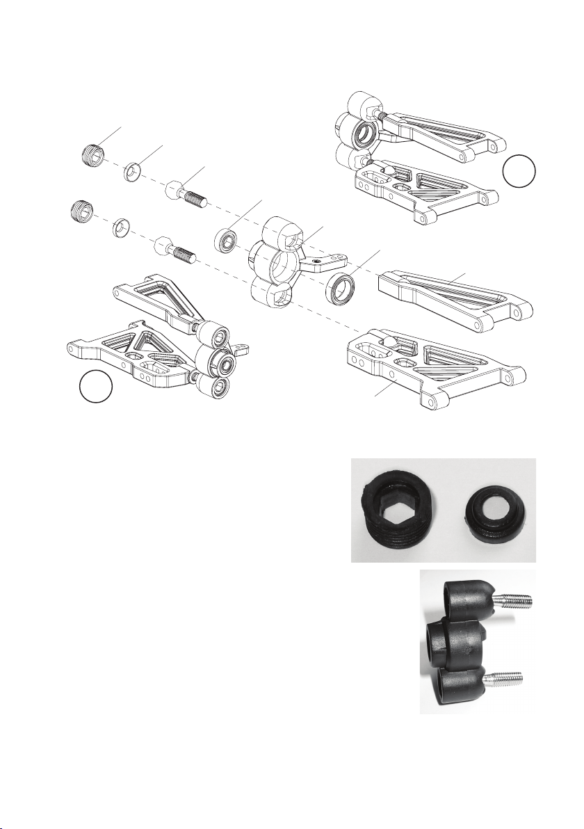
c) Bras oscillant transversal avant
B6
B5
B4
R
K2
B3
K1
B2
L
B1
Deux vis à tête sphérique «B4» sont insérées chacune dans une fusée d'essieu «B3». Ensuite, chacune des vis est
fixée par un coulisseau «B5» et une vis sans tête plastique «B6».
En insérant le coulisseau «B5», veillez à la bonne orientation ; il en
est de même pour la vis sans tête «B6».
Si vous regardez de près la vis sans tête «B6» vous repérerez une
ouverture sur l'une des côtés dans laquelle le coulisseau s'insère
parfaitement. Ce côté de la vis sans tête «B6» doit être orienté vers
le coulisseau «B5» !
Serrez la vis sans tête «B6» à l'aide d'une clé à six pans sans forcer,
de sorte que la vis à tête sphérique «B4» ne vacille pas sans être
pourtant vraiment fixée.
Veillez au bon arrangement des fusées d'essieu pour les côtés gauche et droite du
véhicule. La figure à droite représente la fusée d'essieu droite.
A l'aide d'une petite clé à six pans vous pouvez serrer les vis à tête sphérique dans les
bras oscillants transversaux.
Vissez les vis à tête sphérique sur environ 2/3 de longueur du filet dans les bras oscillants
transversaux.
90
Page 91

d) Bras oscillant transversal arrière
B8
S4 (M3x10)
R
B9
L
B10
K1
B7
K2
Comme pour les bras oscillants transversaux avant, veillez ici aussi au bon arrangement des fusées d'essieu.
Le bras oscillant transversal «B8» est déjà prémonté.
La fixation des deux bras oscillants transversaux supérieurs des fusées d'essieu se fait par les vis M3x10mm.
91
Page 92

e) Support moteur et moteur
Le moteur électrique se fixe par deux vis M3x12mm au support moteur. Ensuite, le pignon est fixé au moteur à l'aide
d'une vis sans tête. A cet effet, un côté de l'arbre moteur est aplati pour éviter que la roue dentée ne puisse vriller.
Fixez le support moteur au châssis à l'aide de trois vis à tête fraisée M3x8mm. La figure à droite
représente le support moteur sans moteur.
Après le montage des deux différentiels (chapitre 7. f et g), occupez-vous de l'orientation exacte
du moteur sur le support moteur (jeu d'engrenage) et du positionnement correct du pignon sur
l'arbre moteur.
Le pignon du moteur doit complètement couvrir la roue dentée principale. Il ne doit pas se
trouver sur une position trop avant ou ou trop arrière sur l'arbre moteur.
La distance entre le pignon et la roue dentée principale doit être réglée ultérieurement aussi
faible que possible.
Les deux roues dentées ne doivent pas tourner strictement ! Cela entraîne une usure élevée de
la roue dentée principale, en plus le moteur perd de puissance (il nécessite déjà beaucoup de
puissance pour tourner la roue dentée principale)l
En cas d'une distance trop grande entre le pignon et la roue dentée principale, les dents de la
roue dentée principale seront cisaillées/arrâchées après peu !
92
Page 93

f) Montage des différentiels au châssis
Vissez deux supports pour bras oscillants transversaux sur la partie
avant de la plaque de châssis. Utilisez à cet effet 4 vis à tête fraisée
(longuer du filet 8mm).
Sur les supports pour bras oscillants transversaux vous trouvez un
marquage «A» et «B» (voir le marquage de cercle dans la figure à
droite).
Respectez la bonne orientation lors du vissage ; vérifiez la position
correcte ; les ouvertures dans la plaque de châssis pour la fixation du
différentiel doivent être dégagées et non couvertes.
Fixez le différentiel avant à l'aide de quatre vis taraudées à tête fraisée
(longueur du filet 10mm).
B
A
Procédez de la même manière pour le montage des bras oscillants
transversaux arrière que pour ceux avant.
Avant de visser le différentiel arrière, insérez l'arbre cardan entre les
deux différentiels.
Ce n'est qu'ensuite que le différentiel arrière peut être fixé sur le châssis
avec quatre vis taraudées à tête fraisée (longueur du filet 10mm).
Ajustez le moteur sur le support moteur si nécessaire pour pouvoir
insérer le différentiel.
Réglez maintenant la distance entre le pignon du moteur et la roue
dentée prinicipale, voir le chapitre 7. e).
B
A
93
Page 94
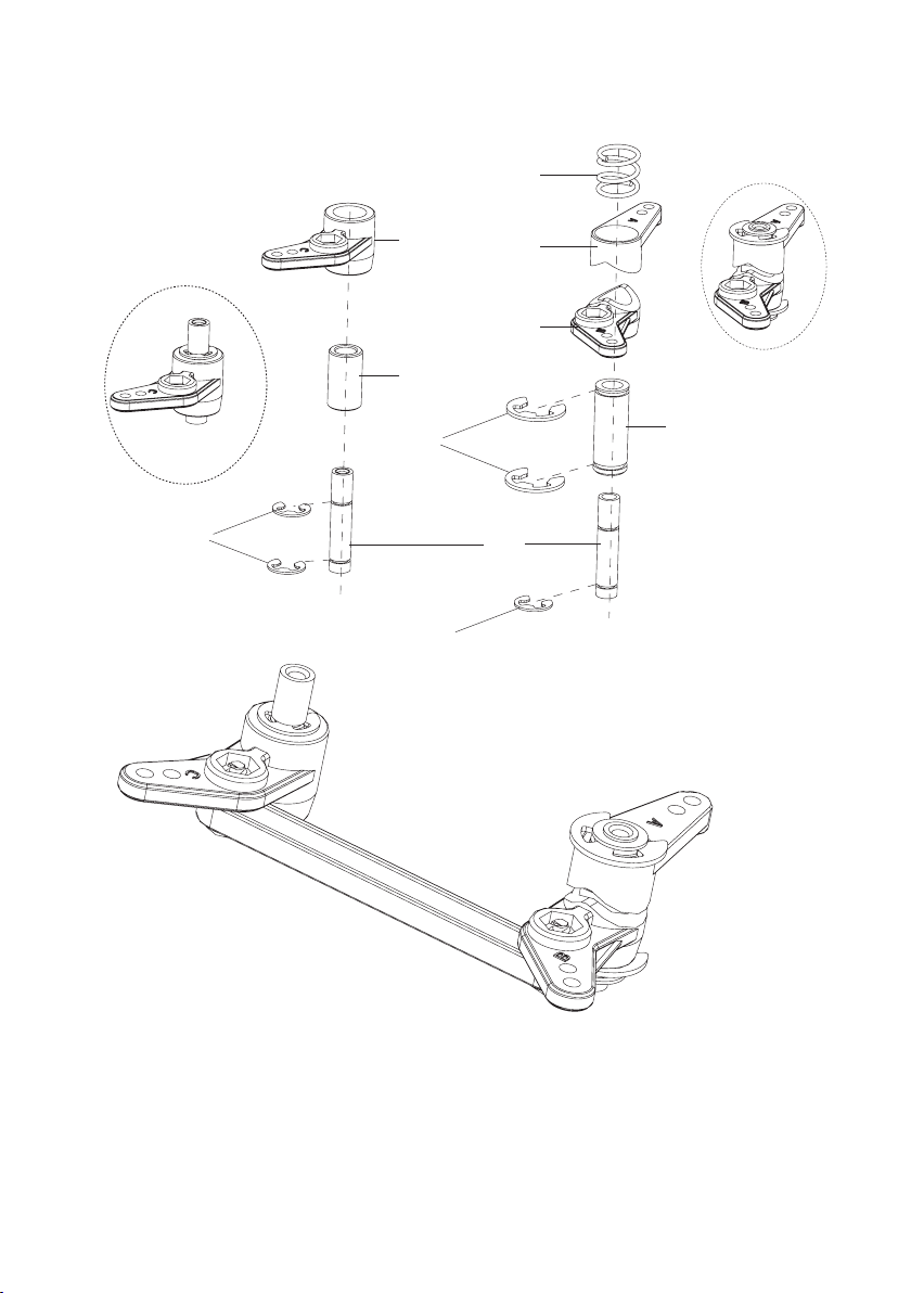
g) Direction
C7
SR2
C4
C2
SR1
SR2
C6
C5
C3
C1
94
Page 95
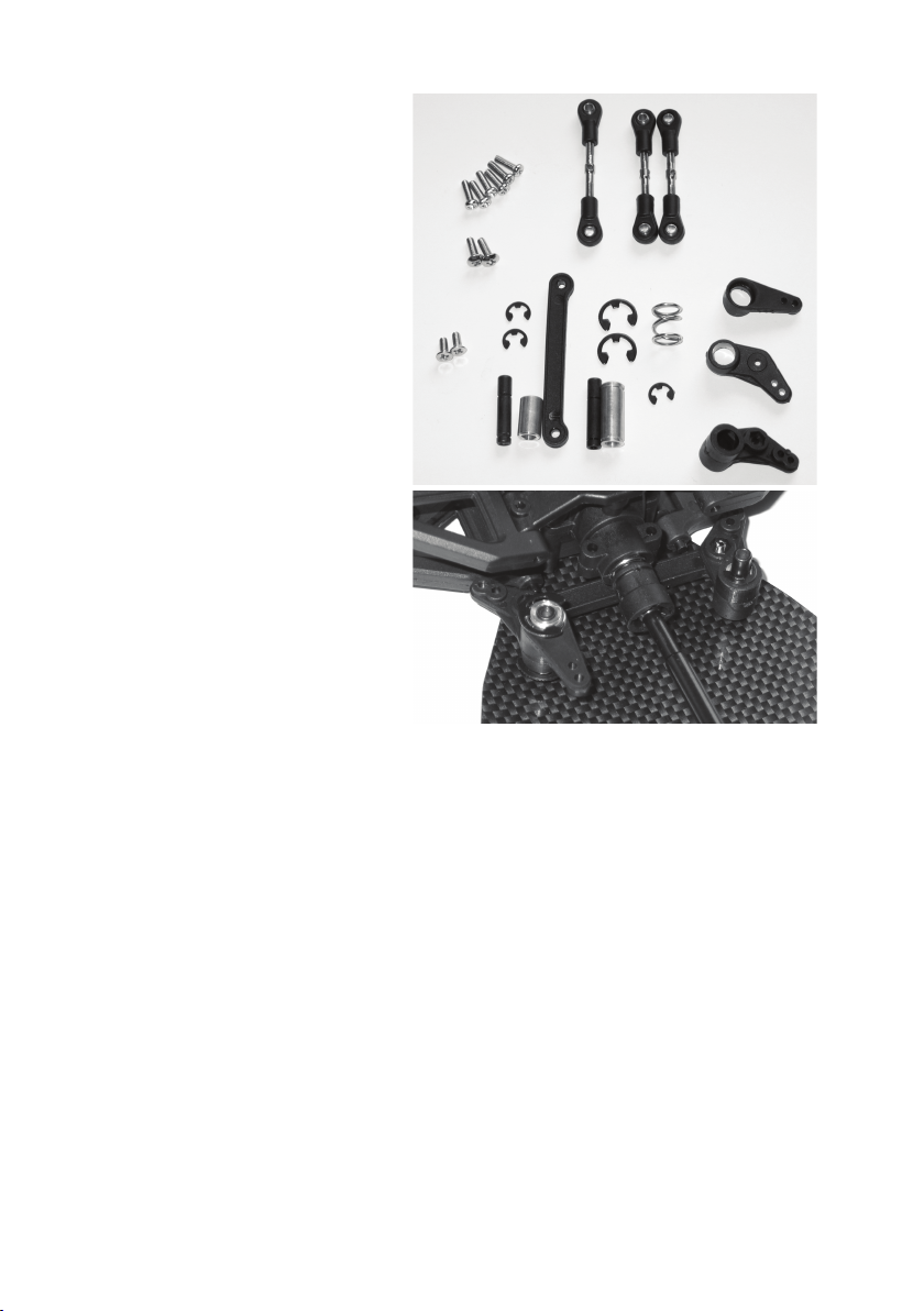
Montez les deux supports pour les leviers de
direction ou le servo saver comme indiqué dans la
figure à la page précédente.
La longue tige de servo «LA2» se monte
ultérieurement entre la timonerie de direction et le
bras du servo.
Les vis à tête fraisée «S6» (M3x6mm) sont utilisées
pour visser les supports assemblés «C1» au châssis.
Les vis «S4» (M3x10mm) servent au montage des
tiges de servo «LA1» et «LA2».
Les vis «S5» (tête plate, M3x10mm) servent au
montage de la tige plastique «VS1» sur la timonerie
de direction («C4» et «C5»).
Le servo saver (la pièce avec le ressort) sert plus
tard à protéger le servo contre toute endommagement par les forces agissant de l'extérieur sur la
direction.
S4 (M3x10mm)
S5 (M3x10mm)
S6
(M3x6mm)
C1
SR2
C2
VS1
LA2
SR1
C1 C3
C7
SR2
LA1
C6
C5
C4
95
Page 96

h) Essieu avant : pont d'amortisseurs, bras oscillant transversal, amortisseurs
Vérifiez la position correcte du roulement à bille «K1» dans la fusée
d'essieu, puis insérez les arbres de roue (D) dans les fusée d'essieu.
Insérez le dogbone (E) entre le différentiel et l'arbre de roue.
Le pont d'amortisseur avant est fixé à l'aide de deux vis taraudées (A)
(longueur du filet de 10mm) au différentiel. Ensuite, chacun des deux
bras oscillants transversaux est à monter à l'aide de deux vis de
connexion (B et C) comme indiqué dans la figure (la longue vis de
connexion est prévue pour le bras oscillant transversal inférieur, la vis
courte pour le bras supérieur).
Montez ensuite le pare-buffe avant avec deux vis à tête fraisée
(longueur du filet de 8mm).
En dernier, les deux amortisseurs (F) sont montés.
La vis M3x12 (G) sert à fixer l'amortisseur sur le pont
d'amortisseur tandis que la vis taraudée (H, longueur
du filet et 15mm) le fixe sur le bras oscillant transversal. Ne forcez pas en serrant les vis !
Fixez l'amortisseur sur les côtés gauche et droite du
véhicule sur les mêmes positions de montage/trous.
Veillez en plus à ce que le manchon plastique à
l'extrémité supérieure de l'amortisseur soit orientée
vers le pont d'amortisseur pour assurer que
l'amortisseur peut se déplacer librement.
F
G
H
C
D
A
B
E
96
Page 97

i) Essieu arrière : pont d'amortisseurs, bras oscillant transversal, amortisseurs
Vérifiez la position correcte du roulement à bille «K1» dans la fusée
d'essieu, puis insérez les arbres de roue (D) dans les fusée d'essieu.
Insérez le dogbone (E) entre le différentiel et l'arbre de roue.
Le pont d'amortisseur arrière est fixé à l'aide de deux vis taraudées
(A) (longueur du filet de 10mm) au différentiel. Ensuite, chacun des
deux bras oscillants transversaux est à monter à l'aide de deux vis de
connexion (B et C) comme indiqué dans la figure (la longue vis de
connexion est prévue pour le bras oscillant transversal inférieur, la vis
courte pour le bras supérieur).
Montez ensuite le pare-buffe arrière avec deux vis à tête fraisée
(longueur du filet de 8mm). De plus, une entretoise transversale doit
être insérée avec deux vis taraudées (longueur du filet de 10mm)
entre le pare-buffe et le pont d'amortisseur.
En dernier, les deux amortisseurs (F) sont montés.
La vis M3x12 (G) sert à fixer l'amortisseur sur le pont
d'amortisseur tandis que la vis taraudée (H, longueur
du filet et 15mm) le fixe sur le bras oscillant transversal. Ne forcez pas en serrant les vis !
Fixez l'amortisseur sur les côtés gauche et droite du
véhicule sur les mêmes positions de montage/trous.
Veillez en plus à ce que le manchon plastique à
l'extrémité supérieure de l'amortisseur soit orientée
vers le pont d'amortisseur pour assurer que
l'amortisseur peut se déplacer librement.
F
G
H
D
B
C
A
E
97
Page 98

j) Servo de direction
SE1
Le servo de direction (non compris dans la livraison, à commander
séparément) se fixe à l'aide des deux équerres support «SE1» sur le châssis.
Utilisez ensuite deux vis M3x10 pour monter la tige de servo réglable entre
le bras du servo et la timonerie de direction.
L'orientation ultérieure du bras du servo sur l'axe de servo ou le réglage de
la tige de servo doivent être effectués après l'achèvement du véhicule
(montage d'un régulateuer de vitesse et d'une radiocommande). A cet effet il
est éventuellement nécessaire de démonter le servo afin de pouvoir ajuster
le bras du servo sur l'axe de servo.
Les équerres support avec le bras du servo sont fixés par 4 vis taraudées à
tête fraisée (longueur du filet de 8mm) sur le châssis.
98
Page 99

k) Revêtement de la boîte de vitesse , pont du châssis
S1
S4
M3 x 10mm
EH1
S2
D'abord les deux courts boulons d'assemblage «HA1» et le
long boulon d'assemblage «HA2» sont montés sur le châssis.
Utilisez à cet effet des vis taraudées à tête fraisée, longueur
du filet de 8mm.
Ensuite, le pont du châssis «CB1» peut être monté.
Les deux vis «S4» (M3x10) sont vissées avec les supports
des leviers de direction.
Les deux vis «S7» (M3x15) sont vissées à travers le pont du
châssis et le revêtement de la boîte de vitesse avec le support
moteur.
Utilisez 2 longues vis taraudées «S2» (longueur du filet de
15mm) pour visser les boîtiers des différentiels avant et arrière.
En dernier vous devez visser 5 vis taraudées «S1» (longueur
du filet de 10mm) avec les boulons d'assemblage et le support
de récepteur «EH1» de sorte que le montage du pont du
châssis soit achévé.
Le support «AN1» pour le petit tube pour antenne est inséré
entre «HA2» et «CB1».
CB1
GA1
AN1
HA2
HA1
S7
M3 x 15mm
S2
S1
S1
HA1
HA1
HA2
EH1
99
Page 100

l) Support d'accumulateurs
Montez les supports d'accumulateurs à gauche et à droite des 6 ouvertures dans le châssis : utilisez à cet effet 2 vis
à tête fraisée (longuer du filet 8mm) pour chaque support.
m) Support du déporteur
Le support du déporteur intègre une goupille pour l afixation de la carrosserie. Assemblez les deux parties latérales
comme indiqué dans la figure. La partie gauche est marquée par «L», celle de droite par «R». Utilisez à cet effet au
total 6 vis taraudées (longueur du filet 12mm).
Le support assemblé est placé sur le pont d'amortisseur arrière et fixé par quatre longues vis taraudées (longueur du
filet 15mm).
Fixez le déporteur fourni avec la livraison sur son support en utilisant deux goupilles.
L'inclinaison du déporteur se règle à plusieurs niveaux par la mécanique intégrée dans le support.
100
 Loading...