

Page 1

Combiboard „QC08“
Item no.: 20 89 44
Version 06/11
Page 2

Table of Contents
1. Introduction .................................................................................................................... 3
2. Intended Use ................................................................................................................. 4
3. Scope of Delivery ........................................................................................................... 4
4. Explanation of Symbols ................................................................................................. 4
5. Product Description ....................................................................................................... 5
6. Safety Information .......................................................................................................... 6
a) General Information ................................................................................................ 6
b) Before Operation .................................................................................................... 7
c) During Operation .................................................................................................... 7
7. Notes on Batteries and Rechargeable Batteries ........................................................... 8
8. Connections and Displays ........................................................................................... 10
9. Connection Options ..................................................................................................... 11
a) Power Supply ........................................................................................................ 11
b) Connecting the Receiver ...................................................................................... 12
c) Composite Output Signal ...................................................................................... 13
d) LED Status Display ............................................................................................... 14
e) Interface Connection ............................................................................................. 15
f) Combiboard Commissioning ................................................................................ 15
g) Servo Connection ................................................................................................. 16
10. Light & Sound Function ............................................................................................... 17
a) Basic Information .................................................................................................. 17
b) Selecting the Light Mode ...................................................................................... 19
c) Selecting the RC Input .......................................................................................... 20
d) Connecting the LED Strips/LEDs ......................................................................... 21
e) Buzzer Configuration ............................................................................................ 23
11. PC Connection ............................................................................................................. 24
12. Maintenance and Care ................................................................................................ 25
13. Disposal ....................................................................................................................... 25
a) General Information .............................................................................................. 25
b) Batteries and Rechargeable Batteries .................................................................. 25
14. Technical Data ............................................................................................................. 26
Page
2
Page 3

1. Introduction
Dear Customer,
Thank you for purchasing this product.
This product complies with the applicable statutory, national and European specifications.
To maintain this status and to ensure safe operation, you as the user must observe these oper-
ating instructions!
These operating instructions are part of this product. They contain important
information concerning operation and handling. Please bear this in mind in
case you pass on the product to any third party.
Therefore, keep these operating instructions for future reference!
All company names and product names are trademarks of the respective owners. All rights
reserved.
In case of any technical questions, contact or consult:
Tel. no.: +49 9604 / 40 88 80
Fax. no.: +49 9604 / 40 88 48
E-mail: tkb@conrad.de
Mon. to Thur. 8.00am to 4.30pm
Fri. 8.00am to 2.00pm
3
Page 4

2. Intended Use
The “QC08” combiboard is solely designed for private use in the model construction area and for
the operating times associated with it.
The product must not become damp or wet. The electronics are designed for use at an operating
temperature from 0°C to +40°C.
This product is not suitable for other types of use. Any other use may damage the product.
Moreover, it would involve dangers such as short-circuit, fire, electric shock, etc. Observe the
safety instructions under all circumstances!
Observe all safety notes in these operating instructions. They contain important information regarding the handling of the product.
You are solely responsible for the safe operation of the model with composite signal
converter!
3. Scope of Delivery
• Combiboard “QC08”
• Receiver connection cable
• Interface foil cable
• Operating instructions
4. Explanation of Symbols
The symbol with the exclamation mark points out particular dangers associated with
handling, function or operation.
The “arrow” symbol indicates special advice and operating information.
4
Page 5

5. Product Description
The electronics are not protected from moisture and other environmental influences
and must only be used inside the model. The inputs and outputs are provided by
common plug connections or to be connected via the included cables.
The “QC08” combiboard is an electronics PCB ready for operation that enables different functions in a model.
1. Use of a common RC receiver for composite signal-controlled models such as the
QuadroCopter.
With a common receiver, a separate control signal is generated for each servo and sent to the
respective servo plug contact at the receiver. The composite signal converter on the combiboard
reassembles the different servo impulses and outputs them as a serial composite signal. Up to
8 channels can be used for formation of the composite signal.
The combiboard can be connected directly to the LiPo flight battery (3s1p) and then supplies the
receiver connected to the composite signal converter with a direct voltage of 5 V/DC.
2.Control of light effects and displays.
• Connection of up to 8 LEDs or LED strips
• Output of different light patterns via the connected LEDs or LED strips
• Control of the light patterns by channels 5 - 8
• Output of acoustic (warning) signals by a buzzer
3.Servo connection
Up to 4 servos (channels 5 – 8) can be connected to the combiboard and are then directly
controlled by the main control of the “QuadroCopter 450”.
5
Page 6

6. Safety Information
In case of damage caused by non-compliance with these safety instructions
the warranty / guarantee will become void. We do not assume any responsibility for consequential damage!
We do not assume any liability for damage to property or personal injury caused
by improper use or the failure to observe the safety instructions! In such cases
the warranty/guarantee is void.
Dear Customer,
These safety instructions are not only for the protection of the product but also for
your own safety and the safety of others. Therefore, read this chapter very carefully
before putting the product into operation!
a) General Information
Caution, important note!
Operating the model may cause damage to property and/or persons. Therefore, make
sure that you are properly insured when using the model, e.g. by taking out private
liability insurance. If you already have private liability insurance, inquire about whether
the operation of the model is covered before operating it.
• The unauthorized conversion and/or modification of the product is prohibited for safety and
approval reasons (CE).
• The product is not a toy and should be kept out of reach of children under 14 years of age.
• The product must not become damp or wet. The electronics are designed for use at an operating temperature from 0°C to +40°C.
• If you do not have sufficient knowledge yet of how to operate remote-controlled models and
RC systems, please contact an experienced model sportsman or a model construction club.
• Do not leave packaging material unattended. It may become a dangerous toy for children.
• Should questions arise that are not answered by this operating manual, contact us (for contact
information, see chapter 1) or another expert.
6
Page 7

b) Before Operation
• Make sure that no other models are operated within the range of the remote control on the
same remote control channel (transmitter frequency). Otherwise, you will lose control of the
remote-controlled models! Always use different channels if you wish to operate two or several
models in direct proximity of each other simultaneously.
• Always switch on the transmitter first and then connect the model’s drive battery at once.
• Check the functional reliability of your model and of the remote control system. Watch out for
any visible damage such as defective plug connections, loose screws or damaged cables.
• Charge the drive battery, which is necessary for operation, as well as the rechargeable battery
needed in the remote control according the instructions indicated by the manufacturer.
• When connecting LEDs, servos or connection lines, ensure secure contact. Loose or loosened plug connections may cause interferences leading to loss of the model.
c) During Operation
• Do not take any risks when operating the product! Your own safety and that of your environment is solely down to you being responsible when dealing with the model.
• Improper operation can cause serious damage to people and property! Therefore make sure
to keep a sufficiently safe distance to persons, animals or objects during operation.
• Fly your model only if your ability to respond is unrestricted. The influence of tiredness, alcohol or medication can cause incorrect responses.
• Never switch off the remote control (transmitter) while the model is in use. After landing, always disconnect the drive battery from the model first. It is only after this that the remote
control may be turned off. Never switch off the transmitter during operation.
• Never expose your model or the remote control to direct sunlight or excessive heat for an
extended period of time.
7
Page 8

7. Notes on Batteries and Rechargeable Batteries
Despite the fact that handling batteries and rechargeable batteries in daily life nowadays is a matter of fact, there are still numerous dangers and problems involved. For
LiPo/Lion rechargeable batteries in particular, various regulations must be observed
under any circumstances due to their high energy content (in comparison to conventional NiCd or NiMH rechargeable batteries), because otherwise there is danger of
explosion and fire.
Ensure that you observe the following information and safety measures when handling batteries and rechargeable batteries.
• Keep batteries/rechargeable batteries out of the reach of children.
• Do not leave any batteries/rechargeable batteries lying around openly. There is a risk of batteries being swallowed by children or pets. If swallowed, consult a doctor immediately!
• Batteries/rechargeable batteries must never be short-circuited, disassembled or thrown into
fire. There is a danger of explosion!
• Leaking or damaged batteries/rechargeable batteries can cause chemical burns to skin when
touched without the use of adequate protective gloves.
• Do not recharge normal batteries. There is a risk of fire and explosion!
Only charge rechargeable batteries intended for this purpose. Use suitable battery chargers.
Batteries (1.5 V) are meant to be used once only and must be properly disposed of when
empty.
• Please observe correct polarity (plus/+ and minus/-)of a battery pack when connecting the
rechargeable battery. Wrong polarity may not only damage the flight model and the rechargeable batteries. There also is a risk of fire and explosion.
• Never charge the enclosed drive battery immediately after use. Always leave the drive battery
to cool off first (at least 10 - 15 minutes).
• Only charge intact and undamaged batteries. If the external insulation of the LiPo battery is
damaged or if the rechargeable battery is deformed or bloated, it must not be charged. In this
case there is serious danger of fire and explosion.
• Never damage the outer cover of a drive battery, do not cut the foil cover, and do not prick the
LiPo battery with sharp objects. There is a risk of fire and explosion!
8
Page 9

• Always remove the drive battery that is to be charged from the model and place it on a fireproof support. Keep distance to flammable objects and never cover the rechargeable battery
or the charger.
• Never charge rechargeable batteries without supervision and only use chargers suitable for
the battery.
• Disconnect the batteries from the charger when they are fully charged.
9
Page 10

8. Connections and Displays
The combiboard has the following connection contacts
or jumper plugs:
PAD1: Plus soldering connection for supply voltage
(+)
PAD2: Minus soldering connection for supply voltage
(-)
LD1: Green LED indicator
LD2: Red LED indicator
X1: Jumper for buzzer
X2: Jumper for light mode
X3: Connection contacts for LED or LED-
strips 1 - 4
X4: Connection contacts for LED or LED-
strips 5 - 8
X5: Connection contacts for servo 1 (channel 5)
X6: Connection contacts for servo 2 (channel 6)
X7: Connection contacts for servo 3 (channel 7)
X8: Connection contacts for servo 4 (channel 8)
X9: Connection contacts for an external RC input
signal
X10: Connection strip for the broad interface cable
X11: Jumper for the interface selection
X12: Serial interface
X13: Connection sockets for the receiver cable
X14: Connection contacts for the composite signal
X15: Programming plug for production-related set-
tings
SW1: Jumper for the RC input selection
SW2: Reset button
BUZ1: Buzzer
For a detailed description of the different
contacts and the connection options, see the
following sections.
Figure 1
X1
BUZ1
SW2
C14
C14
C15
C15
C12
C12
C13
C13
C8
C8
C9
C9
C10
C10
C11
C11
C16
C16
X10
X10
X12
X11
X13
D1
+
X2
R6
R7
R3
R44
R45
R1
R23
R23
SW1
X7
X8
LD2
R43
C4
X14
PAD1
IC1
C1
Q1
Q1
C2
T3
T3
X3
T2
T2
T5
T5
X4
T4
T4
R2
R2
X9
IC2
X5
X6
R21
R22
X15
R41
R42
IC3
LD1
C17
R40
Q2
C18
C19
-
PAD2
C3
10
Page 11

9. Connection Options
Caution, important!
To use the full scope of functions of the combiboard, the QuadroCopter must have
firmware 2.1 or newer. Older QuadroCopter models can be updated to the current
software using the optional configuration sets. The respectively current firmware is
available online for download at conrad.de for the combiboard and QuadroCopter.
If you need more information on the current firmware, contact us (for contact information, see chapter 1).
a) Power Supply
For proper function, the combiboard must be used with the drive battery. For this, solder two
connection lines to the left side of the board, at the solder points “PAD1 (+)” and “PAD2 (-)”. For
the QuadroCopter, you can then lead the lines to the battery connection of one of the two motor
driver PCBs and attach them to the solder connections there.
There also is the option of supplying the combiboard via the balancer plug of the drive battery. In
this case, the 12 V connection lines of the combiboard must be equipped with a suitable plug
connector (like on the balancer connection of the charger). Only the respective outer contacts
are used for this.
Always ensure correct polarity of the connection lines.
Red = positive (+), black =
negative (-).
Attention!
The drive battery voltage is
at the same time supplied to
the combiboard through the
26-core broad cable. The
plug connections are, however, not intended for the
high power loads appearing
when using many LEDs.
+
PAD1
X14
-
PAD2
X13
D1
LD2
C4
R40
Q2
C18
C19
LD1
C17
IC3
R43
R42
R41
X15
R21
R22
X6
Figure 2
11
Page 12

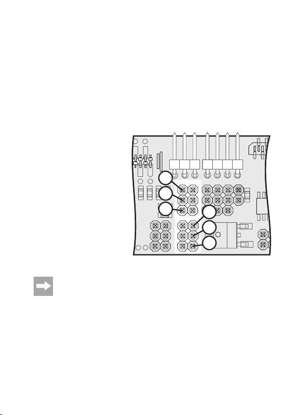
b) Receiver Connection
The receiver is connected to the socket “X13”. A suitable connection cable for this is supplied
with the combiboard. The connection socket “X13” has 10 contacts that are numbered from the
right to the left. Contact 10 is on the left, contact 1 on the right.
The contacts are assigned as follows:
Contact 10 = Channel 1
Contact 9 = Channel 2
Contact 8 = Channel 3
Contact 7 = Channel 4
Contact 6 = Channel 5
Contact 5 = Channel 6
Contact 4 = Channel 7
Contact 3 = Channel 8
Contact 2 = 5 V/DC/Plus (+)
Contact 1 = GND/Minus (-)
+
PAD1
X14
-
PAD2
X13
D1
10
C4
R40
Q2
C18
C19
LD1
C17
IC3
The signals of the 8 inputs (channels 1 – 8) are measured and processed by the composite
signal converter. All available signals are combined into a composite signal pursuant to the
specifications for RC remote control systems (pulse width between 1 and 2 ms). Due to measuring of the signals and signal processing, there will be a delay of one frame length. However, this
has no effect during operation and is therefore only mentioned for the same of completeness.
The measured servo signals may appear in any order, parallel, in sequence or overlapping.
There are no limitations, so that the composite signal converter can be used for all common
systems. A synch break between the different signals is also not required.
To connect the receiver to the included connection cable, best use a servo connection cable.
Shorten it to the required length and then solder it to the open ends of the included receiver
connection cable. The soldering connections are then insulated with a shrink hose.
1
LD2
R43
R42
R41
X15
Figure 3
R21
R21
R22
X6
X6
12
Page 13

For the receiver’s power supply, it is sufficient to solder on the contacts 1 (minus/-)
and 2 (plus/+) to a single servo connection cable.
Important!
Observe that the composite signal converter inputs are assigned without gaps! In a
6-channel system, this means inputs 1 - 6 and not 1 - 4 and then 6 and 7. With this
assignment, the electronics would not recognised channels 6 and 7!
c) Composite Output Signal
The composite signal converter outputs the formed composite signal (SuS) at the upper contact
of the “X14” connection. This composite signal consists of so many single signals as measured
at the inputs. For example, if a 6-channel receiver is used, the composite signal also has 6
channels. Channel number recognition is performed via the valid signal measurement at the
inputs.
After removing the 35 MHz receiver from the QuadroCopter, connect the composite signal cable
to the connection “X14”. The impulse line must be connected to the upper contact of the “X14”
plug.
The "SuS", "+5V" and "GND" are to be connected to the corresponding connections of
the main PCB (Figure 4b) in the QuadroCopter. Observe connection of the two pin
bars with the correct polarity!
PAD1
X14
PAD2
+
-
SuS
+5V
GND
X13
D1
LD2
C4
R40
Q2
C18
C19
LD1
C17
R43
R42
R41
X15
IC3
Figure 4a
R21
R22
X6
Figure 4b
13
Page 14

d) LED Status Display
The composite signal converter has a green and a red LED for status display.
A green LED (LD1) indicates that the
electronics are in normal operation.
This means that servo signals can be
measured and if required a composite
signal can be generated. When the
greed LED goes out, there is a basic in-
+
PAD1
X14
terference in the electronics.
A red LED (LD2) shows that no servo
signals are present. The reasons fort his
may be receipt interference, missing
power supply of the receiver , switchedoff transmitter of contact errors in the
connection lines.
-
PAD2
Behaviour in case of receipt interferences
The composite signal converter measures the signal quality and thus also recognises receipt
interferences. Since channels 1 - 4 are mainly used for general control of models, they are
mainly targeted.
Interferences on channels 1 - 4
For these channels, verification of a valid pulse width (between 1 and 2 ms) is performed. If an
error is recognised, the composite signal is generated with the last valid value.
When the error rate exceeds the measure for proper receipt, the composite signal converter
does not output any composite signal anymore and activates the red LED. Now the receipt
problem can be recognised by the downstream logic and no receipt problems are concealed.
If the input signal is valid again, the red LED goes out and a composite signal is generated.
Interferences on channels 5 - 8
If the receipt interference only acts on channels 5 - 8, a composite signal continues to be generated for channels 1 - 4 and channels 5 - 8 are output with an invalid pulse length.
Thus, it is possible to continue to control the model, but the interference can be recognised by a
downstream logic at channels 5 - 8.
When the input signal is valid again, a regular composite signal is output.
X13
D1
Rot
LD1
C4
R40
Q2
C17
C18
C19
LD1
IC3
R42
Rot
LD2
R41
X15
LD2
R43
Figure 5
R21
R22
X6
14
Page 15

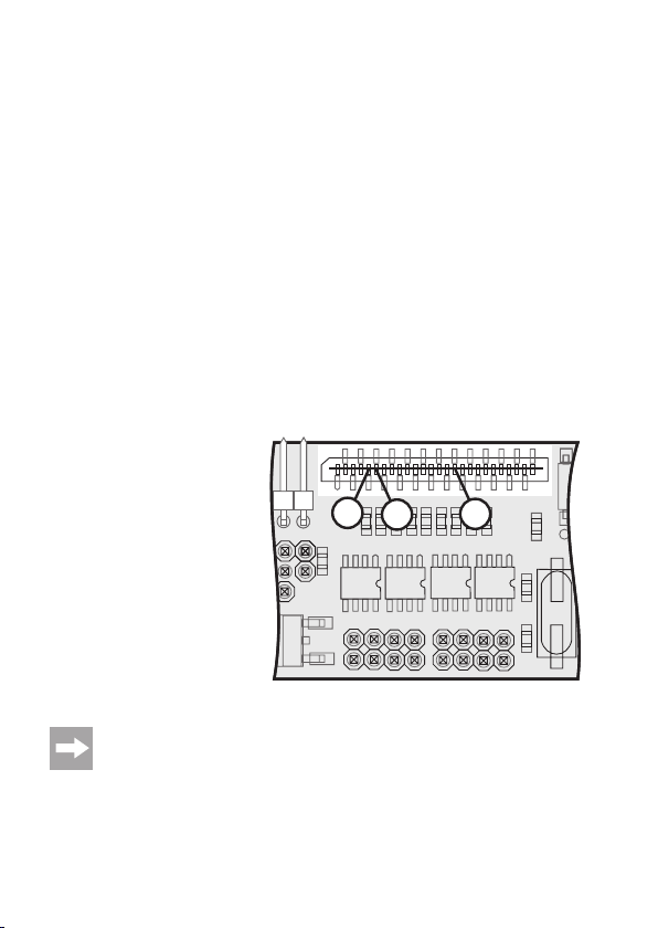
e) Interface Connection
For a connection of the combiboard
to the control board of the QuadroCopter, the combiboard comes with a
26-wire foil cable that must be connected to the connection strip for the
broad interface cable (“X10”).
Later when installing the combiboard
into the QuadroCopter, observe that
the two connection strips for the broad
interface cable (combiboard and control board) are exactly across from
each other.
Connection is performed in the same
way as a connection between the two
motor driver boards and the control
board.
X10
X10
C16
C9
C8
C16
C9
C8
C13
C13
C11
C11
1
R2
R2
T4
T4
X9
IC2
X4
C12
C12
C10
C10
T5
T5
C15
C15
C14
C14
R23
R23
26
T3
T3
T2
T2
X3
Q1
Q1
C2
C3
Figure 6
f) Combiboard Commissioning
When the combiboard is connected to the receiver and the composite signal cable, the supply
voltage and interface foil cable are connected to the QuadroCopter , it is required that you teach
in the channel assignment of the remote control in the QuadroCopter.
The precise approach can be taken from the QuadroCopter operating instructions.
15
Page 16
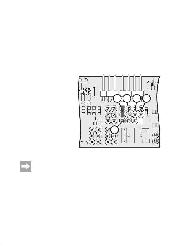
g) Servo Connection
When the combiboard is installed in the QuadroCopter and the remote control was taught in, up
to four servos (channel 5 – 8) can be connected and operated by remote control. However, this
is only possible when the transmitter and the receiver provide these functions and the respective
receiver outputs are connected to the input plug of the composite signal converter (“X13”).
The following plug contacts are intended for the servo connection:
X5: Servo 1 (Receiver output/channel 5)
X6: Servo 2 (Receiver output/channel 6)
X7: Servo 3 (Receiver output/channel 7)
X8: Servo 4 (Receiver output/channel 8)
X10
X10
X11
PPM
X7
X8
LD2
R43
+
R42
R41
X15
R21
-
PPM
R22
+
X5
X6
-
Please observe when connecting the servos that the impulse line (PPM) always has
to be connected to the upper pin of the three contact plugs!
16
X12
SW1
IC2
R2
R2
T
X9
Figure 7
Page 17
10. Light & Sound Function
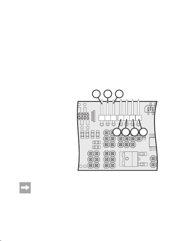
a) General Information
The combiboard has eight LED outputs (“L1” to “L8”), and three digital inputs (“IN-1”, “IN-2”,
“IN-3”) and an external RC input (“PPM”) in addition to the composite signal converter.
Targeting of the LED outputs can be configured via 7 different modes.
The electronics either generate a fixed pattern on the outputs or the outputs are switched de-
pending on the input signals. The jumpers can be used to set modes, which can also be switched
into three states by a RC signal (channels 5, 6, 7, 8 or external). Thus, it becomes possible to
switch during flight.
Digital inputs:
The digital inputs switch the respective outputs when the respective mode was selected. A high
signal (+5 V) means that an output is switched on. The connected LED or the connected LED
strip is lit.
The three digital inputs are located at the interface connection “X10” and are assigned as follows:
IN-1 = Contact 6
IN-2 = Contact 5
IN-3 = Contact 16
Through the 3 digital inputs, different status displays or error messages of the
QuadroCopter can be displayed well visibly. The function of the output signals mainly
depend on the firmware used and can change during further development of the
QuadroCopter.
X10
X10
C16
C9
C8
C16
C9
C8
C13
C13
C11
C11
IN-2
IN-1
R2
R2
T4
T4
X9
IC2
X4
C12
C12
C10
C10
T5
T5
C15
C15
C14
C14
R23
R23
IN-3
T3
T3
T2
T2
Q1
Q1
C2
X3
C3
Figure 8
17
Page 18
A more detailed description with assignment of the 3 digital inputs can be taken from the text file
r
g
g
g
g
g
g
g
g
g
g
of the respective firmware.
RC Input:
Using the RC input, you may switch every light mode to three different switching states. Use a
switch on the transmitter with a centre position (high, neutral, low) or a slider or rotary control.
For switching the light mode, you may use channels 5 – 8 or an externally fed servo signal
(PPM).
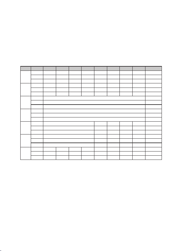
In connection with the 7 different modes, the following light patterns result:
Mode PPM L1 L2 L3 L4 L5 L6 L7 L8 Buzze
High IN-1 IN-2 IN-3 DF SF SB DF Bat Bat
1 Neutral IN-1 IN-2 IN-3 DF SF SB OFF Bat Bat
Low IN-1 IN-2 IN-3 DF SF SB ON Bat Bat
Hi
h IN-1 IN-2 IN-3 DF SF SB DF Bat IN-3
2 Neutral IN-1 IN-2 IN-3 DF SF SB OFF Bat IN-3
Low IN-1 IN-2 IN-3 DF SF SB ON Bat IN-3
Hi
h Running light L1 to L8 IN-3
3 Neutral OFF IN-3
Low Runnin
Hi
h Inverted running light L1 to L8 IN-3
4 Neutral OFF IN-3
Low Inverted runnin
Hi
h Running light L1 to L4 IN-1 IN-3 SB Bat IN-3
5 Neutral OFF IN-1 IN-3 SB Bat IN-3
Low Runnin
Hi
h Inverted running light L1 to L4 IN-1 IN-3 SB Bat IN-3
6 Neutral OFF IN-1 IN-3 SB Bat IN-3
Low Inverted runnin
Hi
h WB1 WB2 IN-1 IN-2 IN-3 SF DF Bat IN-3
7 Neutral WB1 WB2 IN-1 IN-2 IN-3 SF OFF Bat IN-3
Low WB1 WB2 IN-1 IN-2 IN-3 SF ON Bat IN-3
light L4 to L1 IN-1 IN-3 SB Bat IN-3
light L4 to L1 IN-1 IN-3 SB Bat IN-3
light L8 to L1 IN-3
light L8 to L1 IN-3
Meaning of the abbreviations:
SB: Slow Blink (400 ms on, 400 ms off)
FB: Fast Blink (200 ms on, 200 ms off)
SF: Single Flash (50 ms, 1 s pause)
DF: Double Flash (50 ms, 50 ms, 1 s pause)
Bat: Battery warning in 5 stages
(>9.4 V = OFF; <9.4 V = SF; <9.2 V = DF; <9.0 V = SB; <8.8 V = FB)
WB1, WB2: Alternative flashing (alternation every 100 ms)
Running light speed: Alternation every 100 ms
18
Page 19

b) Selecting the Light Mode
You can now set 7 light modes using the jumper plug (“X2”). Depending on the desired mode,
the different contacts must be connected with a jumper. Set the following jumpers for the following modes:
Mode 1: No jumper
Mode 2: Jumper 1 - 2
Mode 3: Jumper 3 - 4
Mode 4: Jumper 1 - 2 and Jumper 3 - 4
Mode 5: Jumper 2 - 4
Mode 6: Jumper 1 - 3
Mode 7: Jumper 1 - 3 and Jumper 2 - 4
SW2
C12
C12
C15
C15
C14
C14
R23
R23
T3
T3
Q1
Q1
C2
X3
BUZ1
X1
R7
R45
R1
C1
R44
IC1
R6
R3
1
3
2
X2
4
C3
5
6
Figure 9
19
Page 20
c) Selecting the RC Input
The desired RC input for switching the light effect can be set using the jumper SW1. Always
connect the upper and lower contacts with the jumper. Assignment is as follows:
Servo selection 1 = channel 8
Servo selection 2 = channel 7
Servo selection 3 = channel 6
Servo selection 4 = channel 5
In the illustration on the side, the jumper is set to servo selection 1. You can now switch the set
light mode at the transmitter via channel 5.
X10
X10
X11
1
X7
X8
LD2
R43
R42
R41
R21
R22
X15
PPM
X5
X6
Control via channels 5, 6, 7 or 8 is only possible where they are also generated by
the main control. Signal generation is independent from the composite signal converter!
If this is not the case, you are able to directly feed an external servo signal (PPM) into
the left connection contact of the “X9” plug of an unassigned receiver output (e.g.
channel 9).
If you do not use any RC input and thus waive the possibility of switching, PPM
switching state “high” will always be active!
20
X12
3
SW1
IC2
4
R2
R2
T
X9
2
Figure 10
Page 21

d) Connecting the LED Strips/LEDs
The combiboard offers the possibility of connecting up to eight LED strips with an operating
voltage of 12 V and a maximum power intake of 1 A/per strip. Even if the MOSFET switching
outputs (FDS6890A) can resist up to 7.5 A, it is recommended not to load the separate outputs
with more than 1 A due to the board layout and cooling.
If you want to connect individual LEDs with a lower operational voltage of only 2 – 3 V, a suitable
dropping resistor (Rv) must be calculated. For calculation of the dropping resistor, you should
use an operational voltage of 12 V, since a freshly charged 3-cell LiPo battery may have far more
than 12 V instead of 11.1 V.
Example calculation:
Assuming that the light diode used has a supply voltage of 2.6 V and a power intake of 20 mA,
first the dropping resistor voltage must be calculated:
12 V – 2.6 V = 9.4 V
If you want to switch two same light diodes in sequence, 2 x 2.6 V = 5.2 V must be
subtracted from the operating voltage of 12 V (12 V – 5.2 V = 6.8 V)
For three same diodes, this is 3 x 2.6 V = 7.8V to be subtracted from the operating
voltage of 12 V (12 V - 7.8 V = 4.2 V).
Now use Ohm’s law R = U : I to calculate the dropping resistance Rv:
Rv = 9.4 V: 0.02 A = 470 Ohm
Use the formula P = U x I to also calculate the output the dropping resistor must be able to
withstand:
9.4 V x 0.02 A = 0.188 W
A resistor with an output of ¼ W (0.25 W) would therefore be sufficient.
The respective upper connection contacts of the plugs “X3” (“L1” to “L4”) and “X4” (“L5” to “L8”)
are intended for the LEDs or LED strip connection. The lower connection contacts are connected to the plus connection (+) of the drive battery (11.1 V of the LiPo battery).
21
Page 22
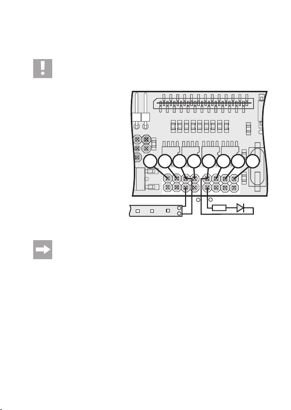
Connection pattern
Image 11 shows the scheme for the connection of a LED with dropping resistor at the output „L1“
and the connection of a 12 V light strip at the output „L7“.
Important!
When connecting LEDs and LED light strips, observe correct polarity of the connection
lines.
X10
X10
C16
C11
C10C9C8
C13
C12
C15
L1
C14
C13
C12
C15
C14
R23
R23
T3
T3
T2
T2
+
Rv
L2
Q1
Q1
L3
L4
C2
X3
C3
LED
C16
C11
C10C9C8
R2
R2
X9
L5
IC2
L6
T5
T5
T4
T4
L8
L7
X4
-
+
12 V
-
Figure 11
In practice, pre-manufactured BEC sockets with open cable-ends have proven well
suitable for LED connection.
22
Page 23

e) Buzzer Configuration
The buzzer can be switched on or off with the jumper („X1“).
When the contacts 1 and 2 are connected with a jumper, the buzzer is off.
When the contacts 2 and 3 are connected with a jumper, the buzzer is on and outputs signals
according to the modes table.
SW2
C12
C12
C15
C15
C14
C14
R23
R23
T3
T3
Q1
Q1
C2
X3
C3
BUZ1
3
X1
2
R7
R45
R1
C1
IC1
1
R6
R44
R3
X2
Figure 12
23
Page 24
11. PC Connection
The Combiboard has a serial interface like the control board of the QuadroCopter. The electronics can communicate with a computer via those interfaces.
Using the jumper „X11“, the serial interface of the combiboard can either communicate with the
control board of the QuadroCopter (2nd internal interface) via the 26-core interface cable or be
switched to the interface connection „X12“. This function is used for future expansions and is
currently without function.
When the contacts 1 and 2 are connected with a jumper, the interface at the control board of the
QuadroCopter is active. When the contacts 2 and 3 are connected with a jumper, the interface at
the Combiboard („X12“) is active.
For the pin assignment of the interface plug „X12“, see figure 13.
3
2
1
X10
X10
X11
X7
X8
LD2
R43
R42
R41
X15
GND
R21
R22
X5
X6
If the computer interface in the computer does not have sufficient power supply for
the electronics in the QuadroCopter, the drive battery must be connected to the
QuadroCopter.
24
X12
SW1
TXD RXD
IC2
X9
R2
R2
+5V
Figure 13
T
Page 25

12. Maintenance and Care
The electronics do not require any maintenance or care but should be protected from outside
influences such as moisture or wetness.
13. Disposal
a) General Information
At the end of its service life, dispose of the product according to the relevant statutory
regulations.
b) Batteries and Rechargeable Batteries
You as the end user are required by law (Battery Ordinance) to return all used batteries/rechargeable batteries. Disposing of them in the household waste is prohibited!
Batteries/rechargeable batteries that include hazardous substances are labelled with
these icons to indicate that disposal in domestic waste is forbidden. The descriptions
for the respective heavy metal are: Cd = cadmium, Hg = mercury, Pb = lead (the
names are indicated on the battery/rechargeable battery e.g. below the rubbish bin
icons shown to the left).
You may return used batteries/rechargeable batteries free of charge to any collecting
point in your local community, in our stores or everywhere else where batteries/
rechargeable batteries are sold.
You thus fulfil your statutory obligations and contribute to the protection of the environment.
25
Page 26

14. Technical Data
Power supply: LiPo rechargeable battery (3s1p) ... 11.1 V
Channel number of composite signal converter ..... max. 8
Servo connections .................................................. 4
Digital inputs ........................................................... 3
LED ports ................................................................ 8
Power resistance per LED output ........................... 1,000 mA
PPM Inputs ............................................................. 1
Dimensions (LxWxH) .............................................. 100 x 30 x 20 mm
PCB weight without cable and plug ........................ Approx. 20 g
Working temperature range .................................... 0 °C to +40 °C
26
Page 27

27
Page 28

Legal Notice
These operating instructions are a publication by Conrad Electronic SE, Klaus-Conrad-Str. 1, D-92240 Hirschau (www.conrad.com).
All rights including translation reserved. Reproduction by any method, e.g. photocopy, microfilming, or the capture in electronic
data processing systems require the prior written approval by the editor. Reprinting, also in part, is prohibited.
These operating instructions represent the technical status at the time of printing. Changes in technology and equipment reserved.
© Copyright 2011 by Conrad Electronic SE.
V3_0611_01
 Loading...