

Page 1

QuadroCopter „650“ ARF
Item no.: 20 93 00
Operating Instructions
¨
¨
Version 11/10
Page 2

1. Introduction .......................................................................................................................................................... 4
2. Intended Use ....................................................................................................................................................... 5
3. Product Description ............................................................................................................................................. 5
4. Scope of Delivery ................................................................................................................................................ 6
5. Explanation of Symbols ....................................................................................................................................... 7
6. Safety Information ............................................................................................................................................... 7
7. Notes on Batteries and Rechargeable Batteries .............................................................................................. 10
8. Final Assembly of the QuadroCopter ................................................................................................................ 12
9. Checking the Configuration ............................................................................................................................... 18
10. Before Each Use ............................................................................................................................................... 25
11. Safety Devices................................................................................................................................................... 27
Table of Contents
a) General Information ...................................................................................................................................... 7
b) Before Operation ........................................................................................................................................... 8
c) During Operation ........................................................................................................................................... 8
a) Transmitter .................................................................................................................................................. 10
b) Flight Battery ............................................................................................................................................... 11
a) Assembly of the Landing Legs .................................................................................................................... 12
b) Assembly of the Rotors ............................................................................................................................... 14
c) Connecting the Receiver ............................................................................................................................. 15
d) Installing the Flight Battery ..........................................................................................................................16
e) Assembly of the Upper Cover Hood ........................................................................................................... 17
a) General Information .................................................................................................................................... 18
b) Programming of Transmitter Channels (General) ...................................................................................... 19
c) Programming of “Throttle” ........................................................................................................................... 20
d) Programming of “Yaw” ................................................................................................................................ 20
e) Programming of “Pitch” ............................................................................................................................... 20
f) Programming of “Roll” ................................................................................................................................. 21
g) Setting the Flight Mode ............................................................................................................................... 22
h) Configuration with PC Software .................................................................................................................. 23
i) Possible Flight Modes ................................................................................................................................. 24
a) Checking the Connections .......................................................................................................................... 25
b) Checking Movable Parts ............................................................................................................................. 25
c) Adjustment of the Neutral Position ............................................................................................................. 25
a) Motor Protection .......................................................................................................................................... 27
b) Emergency Landing .................................................................................................................................... 27
c) Low Voltage Monitoring............................................................................................................................... 27
d) Finder function ............................................................................................................................................ 27
Page
2
Page 3

Page
12. LED Displays ..................................................................................................................................................... 28
a) Ready to Fly ................................................................................................................................................ 28
b) Starting the QuadroCopter .......................................................................................................................... 28
c) Configuration Mode ..................................................................................................................................... 28
d) RC Offset Adjustment.................................................................................................................................. 28
e) Adjustment of the Neutral Position ............................................................................................................. 28
f) Impaired Radio Link before Take-Off .......................................................................................................... 28
g) Impaired Radio Link during Flight Operation .............................................................................................. 29
h) Emergency Landing Function ..................................................................................................................... 29
i) Low Voltage Monitoring............................................................................................................................... 29
13. Combiboard “QC08” Information....................................................................................................................... 30
a) Connection Contacts or Jumper of the Combiboard .................................................................................. 30
b) Composite Signal Output ............................................................................................................................ 31
c) LED Status Display ..................................................................................................................................... 31
d) Interface Connection ................................................................................................................................... 32
e) Servo Connection........................................................................................................................................ 33
14. Light & Sound Function..................................................................................................................................... 34
a) General Information .................................................................................................................................... 34
b) Selecting the Light Mode ............................................................................................................................ 36
c) Selecting the RC Input ................................................................................................................................ 37
d) Connecting the LED Strips/LEDs................................................................................................................ 38
e) Buzzer Configuration................................................................................................................................... 39
15. Combiboard PC Connection: ............................................................................................................................ 40
16. Information for First Take-Off............................................................................................................................. 41
a) General Handling ........................................................................................................................................ 41
b) Starting the Motor ........................................................................................................................................ 41
c) Cutting the Motor ......................................................................................................................................... 41
d) Hover Flight ................................................................................................................................................. 42
e) Yaw .............................................................................................................................................................. 42
f) Pitch............................................................................................................................................................. 42
g) Roll .............................................................................................................................................................. 43
17. The First Flight................................................................................................................................................... 44
18. Maintenance, Care and Repair ......................................................................................................................... 45
a) Regular Cleaning ........................................................................................................................................ 45
b) Replacing the Rotors................................................................................................................................... 45
c) Replacing a Motor ....................................................................................................................................... 45
d) Replacing a Radial Arm .............................................................................................................................. 46
e) Replacing the Complete Frame .................................................................................................................. 46
f) Replacing the Stabiliser Plate ..................................................................................................................... 46
19. Disposal .............................................................................................................................................................47
a) General Information .................................................................................................................................... 47
b) Batteries and Rechargeable Batteries ........................................................................................................47
20. Technical Data ................................................................................................................................................... 48
3
Page 4

1. Introduction
Dear Customer,
Thank you for purchasing this product.
This product complies with the applicable statutory, national and European specifications.
To maintain this status and to ensure safe operation, you as the user must observe these operating instructions!
These operating instructions are part of this product. They contain important information concerning operation and handling. Please bear this in mind in case you pass on the product to any
third party.
Therefore, retain these operating instructions for reference!
All company names and product names are trademarks of their respective owners. All rights reserved.
In case of any technical questions, contact or consult:
Tel. no.: +49 9604 / 40 88 80
Fax. no.: +49 9604 / 40 88 48
E-mail: tkb@conrad.de
Mon. to Thur. 8.00am to 4.30pm, Fri. 8.00am to 2.00pm
Mon to Fri 8.00 am -12.00 pm, 1.00 pm - 5.00 pm
4
Page 5

2. Intended Use
The “QuadroCopter 650 ARF” is a flight model; solely designed for private use in the model making area and the
operating times associated with this.
This system is not suitable for other types of use. Any use other than the one described above may damage the
product. Moreover, it would involve dangers such as short-circuit, fire, electric shock, etc. Observe the safety instructions under all circumstances! The product must not get damp or wet!
The product is not a toy and should be kept out of reach of children under 14 years of age.
Observe all safety notes in these operating instructions. They contain important information regarding the
handling of the product.
You alone are responsible for the safe operation of the model! The chassis is assembled ready for use.
3. Product Description
The electric flight model “QuadroCopter 650 ARF” is pre-assembled as far as possible. In the professional field, such
flight devices are already used for the most diverse of tasks. The latest micro processor controlled electronics with
position control and acceleration sensor stabilise the QuadroCopter.
High quality brushless DC motors paired with a specially developed drive enable long and powerful flight operation
while still providing reserve for transporting loads such as cameras, etc. The novel steering and the electronic selfstabilisation result in excellent flight handling characteristics. Different flying programmes ensure that both beginners
and experts will be able to have their fun.
The QuadroCopter can be used both indoors and outdoors. The in-built electronic controls can balance out small
undesired changes to the flight altitude, but cannot remove them completely. The QuadroCopter weighs relatively little
and this is sensitive to wind. Therefore, ideal flying conditions are complete lack of wind to very gentle and even wind.
The lightweight aluminium designer frame and synthetic components are sturdy and enable excellent flight handling
characteristics. The frame is collapsible and therefore space-saving and easy to transport. The designer frame contains the complete set of electronics and has space for expansion plates. The grid construction makes for good
stability and good protection of the electronics at a low weight.
Due to its construction, the QuadroCopter is designed for experienced model helicopter pilots who do not just want to
carry out helicopter-like, but also sensational moves.
However, this extremely manoeuvrable model is also suitable for beginners! However, before the first flight, we recommend that beginners follow an appropriate training program in a flight simulator for helicopters and/or seek active
assistance from an experienced model helicopter pilot.
The model can be expanded by additional electronics (expansion interface available on the control unit) and the
mounting of several mechanisms on the platform mount fixture on the underside of the grid frame
5
Page 6
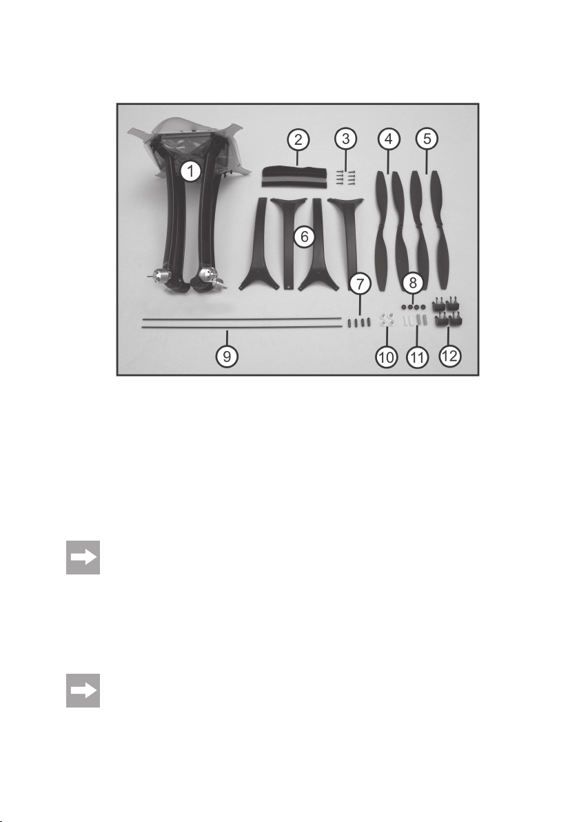
4. Scope of Delivery
Figure 1
1) Pre-assembled QuadroCopter
2) Hook and loop tapes (4 pcs)
3) Screws (8 pcs)
4) Rotors 2x left
5) Rotors 2x right
6) Landing legs (4 pcs)
7) Landing skid end caps (4 pcs)
8) Rubber sleeves (4 pcs)
9) Landing skids (2 pcs)
10) Rotor tips (4 pcs)
11) Silicon hoses (4 pcs)
12) End caps for radial arms (4 pcs)
Not displayed: Operating instruction in German (manual), operat-
ing instructions in English, French and Dutch on CD, aerial tubes,
jumpers (2) high-current plugs for battery connection, hook and
loop tapes for rechargeable battery installation (2) circlips (4) for
rotor tips, self-adhesive rubber buffers (4) and rubber for hood fastening.
The spare parts list is located on our website www.conrad.com in the download section for the respective
product. You can also order the replacement parts list by phone. For contact information, please refer to
the top of these instructions in the chapter “Introduction”.
The following components not included in delivery are required for assembly and operation:
Assembly: Soldering iron and the necessary kit.
Operation:To operate the model, a simple 6 channel remote control system, a 3-cell LiPo flight battery with a mini-
mum capacity of 2500 mAh and a discharge rate of 25 C, as well as a compatible LiPo charging device with LiPo
balance charger are required.
See our catalogues or our website at www.conrad.com for tried and tested accessories.
6
Page 7

5. Explanation of Symbols
The symbol with the exclamation mark points out particular dangers associated with handling, function or
operation.
The “arrow” symbol indicates special advice and operating information.
6. Safety Information
In case of damage caused by non-compliance with these safety instructions, the warranty/guarantee will become void. We do not assume any responsibility for consequential damage!
We do not assume any liability for damage to property or personal injury caused by improper use
or the failure to observe the safety instructions! In such cases the warranty/guarantee is void.
Normal wear caused during normal operation or a crash (e.g. broken rotors or frame) are excluded from
the warranty and guarantee.
Dear customer, these safety instructions are not only for the protection of the product but also for your own
safety and that of other people. Therefore, read this Chapter very carefully before putting the product into
operation!
a) General Information
Caution, important note!
Operating the model may cause damage to property and/or persons. Therefore, make sure that you are
properly insured when using the model, e.g. by taking out private liability insurance. If you already have
private liability insurance, inquire about whether the operation of the model is covered before operating it.
Please note: In some EU countries, you are required to have insurance for any flying models!
• The unauthorized conversion and/or modification of the product or its components is inadmissible for safety and
approval reasons (CE).
• The product is not a toy and should be kept out of reach of children under 14 years of age.
• The product must not become damp or wet. As delicate control electronics are used in the QuadroCopter which are
also sensitive to temperature fluctuations and are optimised for a particular temperature range, operation below
10°C is to be avoided.
• If you do not have sufficient knowledge yet of how to fly remote-controlled helicopters, please contact an experi-
enced model sportsman or a model construction club. Alternatively, it is recommended that you practice on a suitable flight simulator before first use.
7
Page 8

• Do not leave packaging material unattended. It may become dangerous playing material for children!
• The product has been designed for operation in an ambient temperature of between 10°C und 40°C and under
normal air humidity conditions in Central Europe in dry weather. Operation under different conditions can lead to
changed (material) properties and damage to the product as a result.
• The maximum permissible take-off weight of 2,000g must not be exceeded. A take-off weight in excess of this could
lead to damage to the rotors during operation and may cause a crash!
• Should questions arise that are not answered by this operating manual, contact us (for contact information, see
Chapter 1) or another expert.
b) Before Operation
• Observe the operating instructions for the remote control system used by you.
• Regularly check the functional safety of your model and of the remote control system. Watch out for visible damage
such as defective plug connections or damaged cables.
• All moving parts of the model must run smoothly, but should not have any play in their bearings.
• Check before each operation the correct and secure position of the rotors.
• Charge the flight battery, which is necessary for operation, as well as the rechargeable battery that may be inserted
in the remote control according the manufacturer’s instructions.
• If batteries are used as a transmitter power supply, make sure that they have sufficient remaining capacity (battery
checker). If the batteries are empty, always replace the complete set, never individual cells only.
• Always switch on the transmitter first. Please ensure that when you turn on the transmitter the throttle control is set
to the lowest setting (motors off)! Then the flight battery of the model may be connected. Otherwise, unexpected
reactions of the model may occur and the rotors might run unintentionally!
• When the rotors are running, make sure that neither objects nor body parts are in the rotating and suction area of the
rotors.
c) During Operation
• Do not take any risks when operating the model. Your own safety and that of your environment is solely down to you
being responsible when dealing with the model.
• Improper operation can cause serious damage to people and property! Therefore make sure to keep a sufficiently
safe distance to persons, animals or objects during operation.
• Select suitable ground to operate your model.
• Fly your model only if your ability to respond is unrestricted. The influence of tiredness, alcohol or medication can
cause incorrect responses.
• Do not direct your model towards spectators or towards yourself.
• Motor, flight control system and flight battery may heat up during operation of the model. For this reason, please take
a break of 10 to 15 minutes after flying for a maximum of 20 minutes before recharging the flight battery or restarting
with a possible spare battery. The drive motors must have cooled down to ambient temperature.
• Never switch off the remote control (transmitter) while the model is in use. After landing, always disconnect the flight
battery first or switch the model off. Only then may the remote control be switched off.
• In case of a defect or a malfunction, remove the problem before using the model again.
8
Page 9

• Never expose your model or the remote control to direct sunlight or excessive heat for an extended period of time.
• In the case of a severe crash (e.g. from a high altitude). the electric gyro sensors can be damaged and/or misadjusted.
Therefore, full functionality must be tested before flying again without fail. We recommend adjustment to the neutral
position.
• In the event of a crash, the throttle should be immediately reduced to zero. Rotating rotors may be damaged if they
come into contact with obstacles e.g. overcharging. Before flying again, these should be checked for possible tears
or breakages!
• To avoid damage to the QuadroCopter through crashing due to low voltage of the rechargeable battery through total
discharge, we recommend that you respect the low voltage light signals without fail. As the integrated LEDs only
flash in one direction, we recommend that you additionally fit LiPo Saver order no. 230327. The Lipo Saver forewarns you of impending low voltage by light signal. Place the Lipo Saver on the appropriate place of the QuadroCopter.
As an alternative, the integrated combiboard can also be used to display undervoltage via the connected LEDs. For
this, observe the notes in these operating instructions, chapter 14 “Light & Sound Function”
9
Page 10

7. Notes on Batteries and Rechargeable Batteries
Despite the fact that handling batteries and rechargeable batteries in daily life nowadays is a matter of fact,
there are still numerous dangers and problems involved. For LiPo/LiIon rechargeable batteries in particular, various regulations must be observed under any circumstances due to their high energy content (in
comparison to conventional NiCd or NiMH rechargeable batteries), because otherwise there is danger of
explosion and fire.
The QuadroCopter is delivered without remote control, batteries and charging device. Nevertheless, we
are including extensive information on handling batteries for safety reasons. Also observe all documents
and information included with the accessories used (e.g. remote control, rechargeable batteries, charger)!
a) Transmitter
• Keep batteries/rechargeable batteries out of the reach of children.
• Do not leave any batteries/rechargeable batteries lying around openly. There is a risk of batteries being swallowed
by children or pets. If swallowed, consult a doctor immediately!
• Batteries/rechargeable batteries must never be short-circuited, disassembled or thrown into fire. There is a danger
of explosion!
• Leaking or damaged batteries/rechargeable batteries can cause chemical burns to skin when touched without the
use of adequate protective gloves.
• Do not recharge normal batteries. There is a risk of fire and explosion! Only charge rechargeable batteries intended
for this purpose. Use suitable battery chargers.
• When inserting batteries/rechargeable batteries or when connecting a battery pack observe correct polarity
(observe plus/+ and minus/-).
• If the device is not used for an extended period of time (e.g. storage), remove the inserted batteries (or rechargeable
batteries) from the remote control to avoid damage from leaking batteries/rechargeable batteries.
• Recharge the NiCd or NiMH rechargeable batteries about every 3 months, as otherwise there may be a total dis-
charge due to self-discharge, which renders the rechargeable batteries useless.
• Always replace the entire set of batteries or rechargeable batteries. Never mix fully charged batteries/rechargeable
batteries with partially discharged ones. Always use batteries or rechargeable batteries of the same type and manufacturer.
• Never mix batteries and rechargeable batteries!
10
Page 11

b) Flight Battery
Attention!
After the flight, the LiPo flight battery must be disconnected from the electronics system of the QuadroCopter.
Do not leave the LiPo flight battery connected to the electronic system when you do not use it (e.g. during
transport or storage). Otherwise the LiPo flight battery may be fully discharged. This would destroy it and
render it unusable! There is also a danger of malfunction due to interferences. The rotors could start up
inadvertently and cause damage or injury.
• Never charge the LiPo flight battery immediately after use. Always leave the LiPo flight battery to cool off first (at
least 10-15 minutes).
• To charge LiPo rechargeable batteries, always use a LiPo charger and a LiPo equalizer / balancer.
• Only charge intact and undamaged batteries. If the external insulation of the rechargeable battery is damaged or if
the rechargeable battery is deformed or bloated, it must not be charged. In this case there is serious danger of fire
and explosion!
• Never damage the exterior of a LiPo flight battery. Never cut the covering foil. Never stab any LiPo flight batteries
with pointed objects. There is a risk of fire and explosion!
• Remove the LiPo flight battery that is to be charged from the model and place it on a fire-proof support. Keep a
distance to flammable objects.
• As the charger and the rechargeable LiPo flight battery both heat up during the charging procedure, it is necessary
to ensure sufficient ventilation. Never cover the charger or the LiPo flight battery! Of course, this also applies for all
other chargers and rechargeable batteries.
• Never leave LiPo batteries unattended while charging them.
• Disconnect the LiPo flight battery from the charger when it is fully charged.
• Chargers may only be operated in dry rooms. The charger and the LiPo flight battery must not get damp or wet.
There is danger to life from electric shock. There is also the risk of fire or explosion by the rechargeable
battery. Rechargeable LiPo batteries in particular are very susceptible to moisture due to the chemicals
they contain! Do not expose the charger or LiPo flight battery to high/low temperatures or to direct solar
radiation. When handling LiPo batteries, observe the special safety notices of the battery manufacturer.
11
Page 12
8. Final Assembly of the QuadroCopter
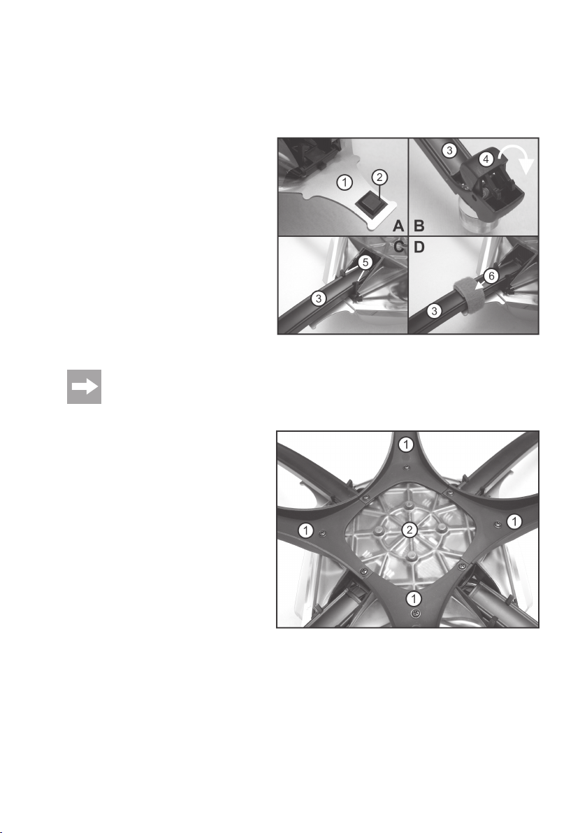
a) Assembly of the Landing Legs
Attach one self-adhesive rubber buffer (2) each to
the four ends of the chassis reinforcement plate
(1) as displayed in figure 2a, item “A”. These rubber buffers are used as stop buffers for the radial
arm (3).
Install the end pieces (4) to the four radial arms (3)
as displayed in figure 2a, item “B” and let the end
pieces catch in the locks.
Completely extend the four radial arms (3) and let
them catch in the locks (5), see figure 2a, item “C”.
Wind the hook and loop tapes (6) firmly around the
radial arm, see figure 2a, item “D”. The red hook
and loop tape must be installed on the radial arm
with a “direction arrow” and thus additionally indicates the “front” of the Quadrocopter.
By installing the rubber buffers (figure 2a, item “A”) and the hook and loop tapes (figure 2a, item “D”), the
connection between radial arms and body is additionally stabilised. At the same time, this type of attachment is sufficiently elastic for dampening harder landings. The measures shown also improve flight characteristics.
Place the Quadrocopter upside-down on a suitable
basis. Install the four landing legs (1) on the bottom of the chassis (2) as indicated in figure 2b. For
this purpose, use the eight screws from the delivery.
The bores in the plastic hood of the chassis must
be carefully drilled with a small drill before installation.
During installation, observe hat the landing legs
have an “upside” on the outsides and a “downside”
on the opposite side, where the hole for the attachment screw is supposed to go.
Figure 2a
12
Figure 2b
Page 13
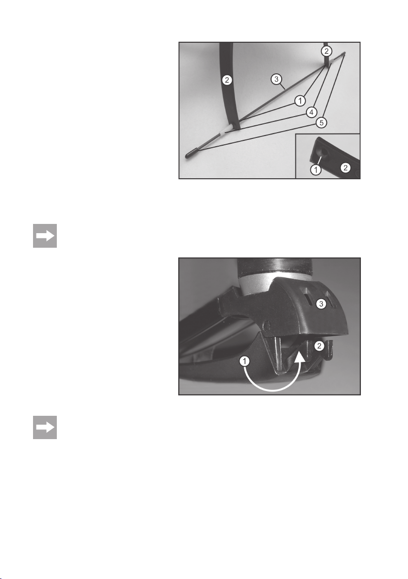
Assemble the four rubber sleeves (1) in the landing leg holes (2). Then push the landing skids (3)
on the rubber sleeves centrally (1).
Now slide the short silicon hoses (4) onto the landing skids (3) from the outside to the rubber sleeves
(1). The rubber sleeves prevent the landing skids
from slipping.
Slide on one end cap (5) each onto the ends of the
landing skids (3).
For normal flight operation, the indicated type of
skid assembly is fully sufficient. For hard flight operation, we recommend additionally securing the
skids and rubber sleeves with a few drops of
superglue.
Optional use of the “QuadroCopter 450” landing legs:
Instead of the landing gear used for the “QuadroCopter 650”, the landing legs of the “QuadroCopter 450”
may also be used. They are not included with the delivery of the “QuadroCopter 650”, but can be ordered
as a spare part (see spare part list of “QuadroCopter 450”).
Figure 2d shows the landing legs of the “QuadroCopter 450”.
Extend the landing legs (1) into flying position. The
retaining clips (2) must catch clearly noticeably in
the slots (3).
For folding in, slightly push the retaining clips (2)
into the slots (3) with a small screw driver in order
to avoid breaking the plastic parts.
A red direction indicator is mounted to one of the
landing legs. This direction indicator should always
be considered as “forwards” when flying.
Figure 2c
Figure 2d
In harder landings, the landing legs will fold in. This is normal and desired. Should you wish to avoid this
effect or if you no longer wish to fold away the landing legs for transportation, you can also permanently
affix the landing legs using superglue.
13
Page 14
b) Assembly of the Rotors
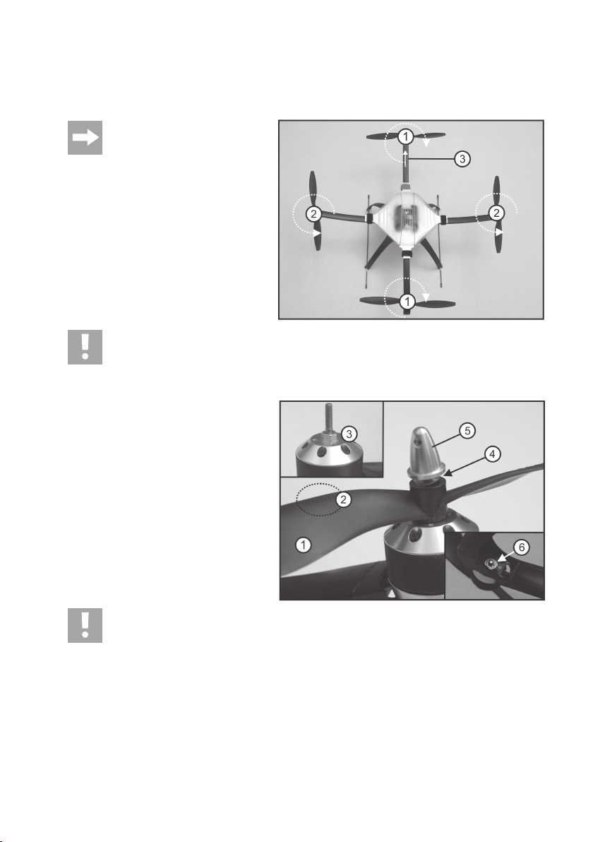
The rotating direction of the rotors can be seen in the adjacent figure (bird’s eye view). The arrow on the radial arm is
to be used as the indication for the direction of the model and is deemed to be “front”.
Attention!
As the motors are pre-assembled, the
rotating direction of the rotors on the
basis of the flight direction should be
carefully observed (figure 3)!
The rotors in the centre line (1) turn clockwise (right
rotating) and must be marked with the inscription
“RIGHT”.
The rotors on the cross axis (2) turn anticlockwise
(left rotating) and must be marked with the inscription “LEFT”.
The arrow at the radial arm (3) indicates “front”.
Attention!
If the rotors are not installed as described, the programmed rotating directions will no longer be in line with
the rotating directions of the rotors. The QuadroCopter is therefore no longer able to fly and can no longer
be operated! Loss of guarantee/warranty!
Rotors and motor shafts are provided with a hexagonal bolt (3).
Place the rotors (1) on the motor shafts (3) so that
they lock into place in the hexagonal bolt. Observe
the indication of “RIGHT” and “LEFT” on the rotors
(2).
Now insert one of the provided spring washers (4)
at a time between the rotor and rotor tip (5), as
otherwise the rotors may become loose during
flight.
Tightly screw the rotor tips to the motor shafts using a small pen or screw driver.
Figure 3
14
Attention!
Tightening the screws too much can damage the motors. The shafts may tear or be pulled from the
bearings. The motors operate sluggishly, which may have a negative effect on the flight characteristics.
Therefore, please verify that all of the rotors can turn easily after tightening the rotors. The snap ring shown
in figure 4, item 6, on the underside of the motors must be able to move and must not jam.
Please ensure before each operation that the rotors are firmly screwed in place on the motors. It is recommended that you are careful when handling work tools.
Figure 4
Page 15
c) Connecting the Receiver
The receiver is connected to the “X13” connection socket of the combiboard (1). A suitable connection cable (2) is
supplied with QuadroCopter. The connection socket “X13” has 10 contacts that are numbered from the right to the left.
Contact 10 is on the left, contact 1 on the right.
The contacts are assigned as follows:
R41
X15
R43
1
LD2
Figure 5
Contact 10 = Channel 1
Contact 9 = Channel 2
Contact 8 = Channel 3
Contact 7 = Channel 4
Contact 6 = Channel 5
Contact 5 = Channel 6
Contact 4 = Channel 7
Contact 3 = Channel 8
Contact 2 = 5 V/DC/Plus (+)
+
PAD1
X14
-
PAD2
C18
C19
Q2
D1
10
X13
C4
R40
C17
LD1
R42
IC3
Contact 1 = GND/Minus (-)
The signals of the 8 inputs (channels 1 – 8) are measured and processed by the composite signal converter. All
available signals are combined into a composite signal pursuant to the specifications for RC remote control systems
(pulse width between 1 and 2 ms). Due to measuring of the signals and signal processing, there will be a delay of one
frame length. However, this has no effect during operation and is therefore only mentioned for the sake of completeness.
The measured servo signals may appear in any order, parallel, in sequence or overlapping. There is no limitation, so
that the composite signal converter can be used for all common systems. A synch break between the different signals
is also not required.
For the receiver’s power supply, it is sufficient to connect the contacts 1 (minus/-) and 2 (plus/+) to a single servo
connection cable.
Important!
Observe that the composite signal converter are assigned without gaps! In a 6-channel system, this means
inputs 1 - 6 and not 1 - 4 and then 6 and 7. With this assignment, the electronics would not recognised
channels 6 and 7!
Due to the many remote control receiver sizes and builds on the market, we cannot give any concrete
installation notes for the receiver. Depending on the receiver used, you may either install it between the
PCBs in the grid frame of on the reinforcement plate.
If the PCBs in the grid frame must be repositioned for installation of the receiver, we recommend installing
the main PCB of the gyro precisely at the centre for best flight characteristics (it is located on the small,
protruding PCB).
R21
R22
X6
R21
X6
15
Page 16
d) Installing the Flight Battery
The flight battery is not included. Take the following steps to install the flight battery:
Solder the supplied high power loading system to the connecting cable of the rechargeable battery. Always ensure
correct polarity.
The red electronics system cable of the QuadroCopter must be connected to the positive cable of the rechargeable
battery and the black cable to the negative cable of the rechargeable battery.
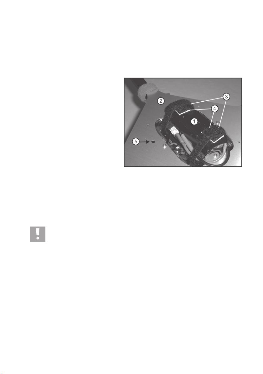
Install the rechargeable battery (1) in the frame (2)
and attach it with hook and loop tapes (3).
In addition to the indicated hook and loop tape, also
attach a strip of hook and loop tape to the surface
of the battery (4 - as supplied) to prevent it from
slipping forwards or backwards. The connecting
cables can also be fixed under the hook and loop
tape (3) as shown in the figure.
The rechargeable battery must be placed in the
centre so that the QuadroCopter is not tailheavy, top-heavy or side-heavy.
The reinforcement plate of the chassis (2) has a
bore intended for an aerial tube (5). You can use
the aerial tube to guide a receiver aerial outside.
The upper covering hood also has a hole in this
position.
The QuadroCopter’s electronics system has a safety device to prevent inadvertent engine start-up. When contact is
made with the rechargeable battery although the transmitter is not switched on or the speed/pitch control stick was not
set to zero, the control electronics in the model will not cause the engines to start.
When the transmitter is switched on and the speed/pitch control stick is set to zero once, the control electronics in the
model clears normal operating state.
Caution:
To prevent inadvertent engine start-up if the safety device fails, the transmitter should be switched on. The
speed/pitch control stick must be set to zero so that no acceleration command is sent.
Figure 6
16
Page 17

e) Assembly of the Upper Cover Hood
Due to the position of the aerial pipe and the predrilled hole in the upper hood, the hood can only
be mounted in one position.
Attach the upper cover hood (1) with a rubber band
(2) as shown in figure 7.
The rubber bands must be slid under the radial
arms of the reinforcement plate at the front and
back.
The hood must be attached so that the hole for the
aerial tube (3) is above the hole in the reinforcement plate (see previous chapter).
Figure 7
17
Page 18

9. Checking the Configuration
a) General Information
Please carry out the configuration of the QuadroCopter as described in this chapter. Programming of the channels is
essential, since otherwise the QuadroCopter will not recognise your transmitting equipment. When you have carried
this out, your QuadroCopter is ready to fly.
If you are using a computer remote control, programme it without using a mixer in the standard program.
To correctly align the pilot stick for the desired control commands, it is necessary to programme the QuadroCopter with
the transmitter used. In the process, the QuadroCopter’s electronics system memorises the channel on which each
control command is broadcast. Generally, you can freely choose the configuration of the control lever (according to
your habits), however, it is recommended that beginners follow the recommended examples.
Ex factory, the QuadroCopter is configured to “mode 2”. The examples are for a common assignment used by many
model pilots.
Decide which configuration you wish to program and programme the channels correspondingly. Further possibilities
for control modes 1, 3 or 4 (modes 1, 3 or 4) can be found in the instructions in this chapter under the heading
“Possible Flight Modes”.
For monitoring the configuration, indicating malfunction or operating status, a red and a green LED are installed on the
control board. The respective indications can be seen in the table in the following chapter “safety devices” in this
instruction manual.
When using multiplex remote controls, the servo protocols must be adapted for all four functions (throttle,
roll, pitch and yaw) from “MPX” to “UNI”.
If the QuadroCopter cannot be programmed onto your remote control, this may be due to the reverse
function of your remote control. We recommend pressing the reverse switch for the throttle function and retrying programming.
18
Page 19

b) Programming of Transmitter Channels (General)
Before you begin programming, unplug the rechargeable battery, if connected, from the
QuadroCopter. Also disconnect the connection cable to the PC, if connected, from the QuadroCopter.
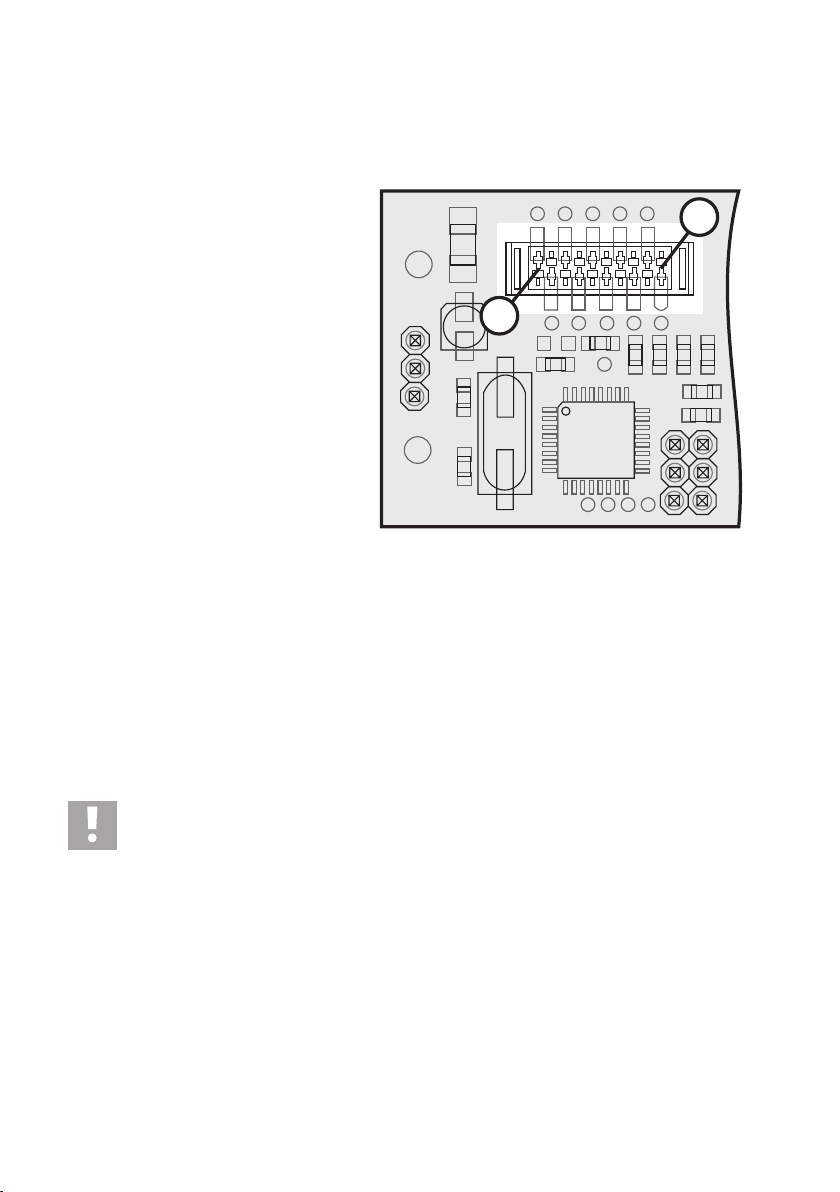
Use a jumper for the RC configuration setting “R2”
for “remote setting” (5). You will find the plug connectors for the jumper in the right upper area on
the reverse of the control board of the
QuadroCopter.
On one side of the board (1), both of the LEDs (2)
indicate particular operating statuses. On the opposite side of the board (3), the plug connectors
“S1, S2, R1, R2” (4) for the jumpers are to be seen.
Figure 8
To operate the QuadroCopter in “remote setting” mode, affix the jumper “R2” (5) as shown in figure 8. This setting is
independent from other affixed jumpers.
Important!
Before switching the transmitter on, please set the throttle stick to “motors off” and all trim levers / trim
sliding controllers of the pilot stick to the neutral position. Otherwise, the QuadroCopter may not recognise
the transmitter after the battery is connected.
Now switch on the transmitter and pull out the telescopic aerial of 27-/40 MHz remote control systems completely.
Please ensure that all levers and trims of the transmitter are in neutral position. The examples given show the procedure using a remote control in mode 2. If you prefer to use another mode, the used axes may differ (see chapter
“Possible Flight Modes”)!
Please also ensure that the sliding controller for the trim is set to neutral position! Otherwise correct recognition of the
channels will not be possible!
Please also ensure that lever movements are made
in the right direction, otherwise the signals will be
memorised in reverse! Computer remote controls
should always be operated without mixer!
Move the throttle lever (see figure 9) backwards to
the neutral position (motor off), all other control
devices should be set to neutral.
Do you want to try out “pitch reverse”? (during “motor off” the pilot stick for throttle is pulled away from
the body), then bring the throttle lever forwards into
the max. position before you connect the rechargeable battery.
Figure 9
19
Page 20

c) Programming of “Throttle”
Connect the charged battery to the QuadroCopter. The model starts with a self-test and directly continues with programming of the channels. On the basis of the throttle setting, the QuadroCopter automatically recognises which
channel you would like to use for the throttle.
As a confirmation, the red LED of the QuadroCopter flashes in groups of 2 (2 short flashes, then a longer pause, then
2 short flashes again etc.)
d) Programming of “Yaw”
Now move the yaw lever (see figure 10) to the left
to full deflection and hold it there for at least one
second.
The QuadroCopter thus recognises the YAW channel and memorises this.
Move the YAW lever back to neutral position with
the THROTTLE still on zero.
As confirmation, the QuadroCopter’s red LED
flashes in a cycle of 3s (3 short flashes, then a pause
etc.)
During the respective configuration
step, the green LED shows the channel as long as the lever is still being
pushed! However, only the red LED is
important for the progress indicator!
During the programming process, please ensure that you only move the required lever, otherwise the setting will not
be recognised!
Figure 10
e) Programming of “Pitch”
Move the PITCH lever (see figure 11) to full deflection for GIVE PITCH upwards and hold it there for
at least one second.
The QuadroCopter thus recognises the PITCH
channel and memorises this. Move the PITCH lever back to neutral position, continue to leave the
THROTTLE on zero.
As confirmation, the QuadroCopter’s
red LED flashes in a cycle of 4s (4x
short flashes, then a pause etc.).
20
Figure 11
Page 21

f) Programming of “Roll”
Move the ROLL lever (see figure 12) to full deflection for ROLL LEFT and hold it there for at least
one second.
The QuadroCopter thus recognises the ROLL channel and memorises this. Move the ROLL lever back
to neutral position, continue to leave the THROTTLE on zero.
As confirmation, the QuadroCopter’s red LED goes
off and the green LED is lit permanently. This is the
end of the training process.
Disconnect the rechargeable battery from the
QuadroCopter and remove jumper “R2”.
Other possibly connected jumpers may be left
plugged in. This is the end of the programming process for the channels.
Figure 12
21
Page 22

g) Setting the Flight Mode
The QuadroCopter offers three different flight modes.
• Beginner (suitable for novices)
• Sport (suitable for proficient QuadroCopter pilots; lower axis limits and higher dynamics)
• User (flight parameters adjustable with PC software, see chapter “configuration with PC software”)
The flight mode is configured before switch-on by setting the jumpers “S1” and “S2” and cannot be altered during
operation. The positions for the jumpers are on the control board (also see figure 8 in chapter “Programming of
Transmitter Channels”)
Practical advice:
Beginners in particular are urgently advised to reduce the directness of the control command with which
the QuadroCopter performs the commands from the remote control around the centre detent (negative
exponential “expo”).
To illustrate:
Normally, the QuadroCopter responds linearly. This means that the pilot stick deflection and the reaction are synchronous. With negative expo, the QuadroCopter will respond relatively sluggishly at the start of the controlling motion. In
the case of stronger control deflections, however, it responds much more strongly to the control command. This is
particularly beneficial for beginners who initially tend to oversteer, i.e. move the control stick of the remote control more
intensely than necessary. This effect is, of course, only desired for the three control axes (roll, pitch and yaw) and not,
however, for throttle. Thus: Do not configure expo on throttle!
In other words: With negative expo, slow behaviour of the flying device is achieved on the controlling motions in the
area of the centre detent of the pilot stick. This takes place either via the optionally available software, via the
QuadroCopter’s jumpers (see “beginner mode”) or via the existing “expo function” of the remote control. Only computerised remote controls can set “expo”. However, care must be taken, since the higher the negative expo selected, the
more aggressively the QuadroCopter reacts when the control stick is moved in the area of full deflection.
The following table illustrates the different settings of the jumper. Jumpers are not set ex factory and the QuadroCopter
is set to beginner mode. The jumpers “S1” and “S2” are independent from the other jumpers!
Beginner Sport User
22
For the “user” flight mode, you must configure your own setting with the optionally available configuration
software. For this, you can use either the beginner or sport modes as a basis and customise your own
personal requirements. Please observe the operating instructions for the configuration sets.
Page 23

h) Configuration with PC Software
To fly the QuadroCopter with your own settings, you may connect the electronics system of the QuadroCopter to a PC
via an interface cable (serial TTL on USB).
An optional PC configuration set is available for this. This contains a connection cable, a detailed description and the
software on CD. This kit may be used with Microsoft® Windows XP®*, Windows Vista®* and Windows 7®* (* Microsoft,
Windows XP, Windows Vista and Windows 7 are registered trademarks of the Microsoft Cooperation in the U.S. and
other countries).
As it is not necessary to carry out configuration with a PC for normal flight operation, this is only mentioned here as a
side note. More information on the configuration can be found in the software operating instructions.
When jumper “R1” is set, the QuadroCopter is in PC configuration mode (PC mode) and cannot be flown. Remove this
jumper for normal flight operation!
On the control board below the LEDs, a micro push button is mounted which can be used to reset the
control electronics. For this, press the micro push button with the rechargeable battery connected for
around 1 second. Then the electronics will restart and start in the status set according to each jumper. The
effect is the same as for “unplug flight battery”.
The micro push button (1) and the interface (2) are
on the control board (3). For photo-technical reasons, the circuit board of the control board was
uninstalled for figure 13.
Figure 13
23
Page 24

i) Possible Flight Modes
Mode Throttle Yaw Pitch Roll
1
2
3
4
24
Page 25

10. Before Each Use
a) Checking the Connections
Check all screws for tightness before transport and flights. Vibration during transport and flight may cause screws to
loosen. Due to this, you need to conduct a thorough pre-flight check just as for a real helicopter.
b) Checking Movable Parts
Always check all movable parts and all parts with bearings for unobstructed movement before flying. They must be
easy to move, but without play.
c) Adjustment of the Neutral Position
For the stabilisation of the QuadroCopter to work correctly, the neutral position must be set. This is the position that the
QuadroCopter tries to stabilise as long as no other flying manoeuvre is desired.
Proceed in the following sequence:
1) Switch on the transmitter.
2) Set THROTTLE to zero and all other levers and trims to the neutral position.
3) Place the QuadroCopter on a level, even surface!
4) Connect the rechargeable battery to the QuadroCopter.
5) The QuadroCopter’s red LED must be OFF and the green LED must be ON.
6) Move THROTTLE to full deflection and YAW to full deflection
on the right (figure 14).
7) The QuadroCopter’s green LED flashes as confirmation and the neutral position is memorised.
8) Move the THROTTLE back to zero, move YAW, PITCH, and ROLL into the neutral position.
9) The red LED is OFF and the green LED in ON –> the QuadroCopter is now ready to fly!
Figure 14
25
Page 26

If you do not set the neutral position , the QuadroCopter will use either the factory settings or the last saved value!
It is very important that you set the neutral position of the QuadroCopter as precisely as possible. For this,
it is necessary to set the neutral position on a completely horizontal base. Ideally, this should be measured
with a spirit level.
Due to different environmental conditions than in the factory and/or at the actual place of flight operation, the factory
settings may not be ideal! It is therefore urgently recommended that you set the neutral position before first flight.
If the QuadroCopter still swerves in one direction despite the relevant trims to the transmitter, the neutral position must
be stored again by slightly lifting up the QuadroCopter on the side to which it swerves. This way, the (changed) position
is saved as the new centre position.
26
Page 27

11. Safety Devices
The QuadroCopter has a range of safety devices which protect the model from damage and/or should reduce possible
damage to a minimum. The protection mechanisms are identified by LED indicators. For this, please observe the
following chapter 12 “LED Displays”.
a) Motor Protection
The control electronics has a motor protection which immediately switches off all motors if one rotor is blocked (e.g.
after a crash). After possible damage has been checked for, the motors can be restarted using the normal control
command “starting the motors”.
b) Emergency Landing
If the control electronics of the QuadroCopter detects too great interferences, it tries to realign the QuadroCopter in a
level position.
If interference of the receiver continues, the throttle is set to a value just under hovering (without rear weight) and the
QuadroCopter begins its descent.
When the interference of the receiver is over, the model pilot can give another control command and the emergency
landing programme is terminated.
c) Low Voltage Monitoring
The QuadroCopter constantly monitors the voltage of the connected battery. If it falls below a critical level over a
particular period of time, this will be indicated by the LEDs.
In this case, the red LED flashes and the green LED will be permanently lit. This indicator can only be switched off by
disconnecting the battery.
In order to detect a low rechargeable battery during flight, it is recommended that strong throttle thrusts be carried out
from time to time. If the QuadroCopter responds slowly and weakly, it should be landed and the rechargeable battery
should be checked. Due to the performance, this test is, however, difficult to realize.
In the case of a long, uninterrupted flight operation, it is recommended to also test the LED indictors through time to
time landing.
Practical advice: To avoid damage to the QuadroCopter from crashing due to undervoltage and/or to the rechargeable battery due to total discharge, we recommend that you always observe the low voltage light signals. As the
integrated LEDs only flash in one direction, we also recommend installing the LiPo Saver (Conrad item no. 230327).
The Lipo Saver warns you of impending low voltage by light signal. Place the LiPo Saver on the appropriate position
on the QuadroCopter and connect it to the battery via, e.g., the balancing connector.
d) Finder function
When there is no transmitter signal or when the transmitter is off, the activated QuadroCopter automatically emits an
acoustic signal (beeps).
In case of landing outside in high grass or in a grain or corn field, it can thus be easily recovered.
27
Page 28

12. LED Displays
The following LED display options are not safety indicators, but only indicate particular operating statuses. You will find
the LEDs for the displays described in the following on the control board (see figure 8).
a) Ready to Fly
After you have plugged in the flight battery and before starting the motors, the green LED lights up and the red LED is
off. Your QuadroCopter is ready to operate. If this is not the case, there is an interference. Please observe the following
operating instructions in this chapter.
b) Starting the QuadroCopter
Rev the motors. The red LED now lights up permanently and the green LED flashes. After approx. two seconds, the
green LED also lights up permanently. If this is not the case, there is an interference. Please observe the following
operating instructions in this chapter.
c) Configuration Mode
During the configuration of the remote control, the red LED indicates the programme step and the green LED indicates
the channel to be programmed through corresponding flashing with pauses.
d) RC Offset Adjustment
After the flight battery is connected, the red and green LEDs flash quickly and indicate the alignment of the transmitter
and electronic system of the QuadroCopter . After successful alignment has taken place, the red LED goes off and the
green LED is permanently lit.
e) Adjustment of the Neutral Position
If an adjustment to the neutral position is carried out, the green LED flashes quickly. The red LED is off.
The following LED display options are safety indicators. The causes for this must be explored and resolved.
f) Impaired Radio Link before Take-Off
You want to take off and the engines are still off. The red and the green LEDs flash slowly at the same time and
indicate a faulty radio link.
Possible causes: Receiver crystal has fallen out of the base, receiver crystal is defective, receiver aerial has broken
off. Transmitter aerial not pulled out, second transmitter with the same transmitter channel switched on/ batteries from
transmitter empty. Check the possible causes and restart.
If there is any permanent radio interference during flight, the QuadroCopter will start an emergency landing and the
LEDs will also indicate an impaired radio link here by simultaneous flashing.
28
Page 29

g) Impaired Radio Link during Flight Operation
You want to take off and the engines are already switched on or during flight operation. The red and the green LEDs
flash slowly at the same time and indicate a faulty radio link.
Possible causes: Receiver crystal has fallen out of the base, receiver crystal is defective, receiver aerial has broken
off. Transmitter aerial not pulled out, second transmitter with the same transmitter channel switched on/ batteries from
transmitter empty. Check the possible cause and restart.
If there is any permanent radio interference during flight, the QuadroCopter will start an emergency landing and the
LEDs will also indicate an impaired radio link here by simultaneous flashing.
h) Emergency Landing Function
During operation, a permanent radio interference prevails. The QuadroCopter starts an emergency landing independently. The red and green LEDs flash slowly and simultaneously. Look for possible error causes on the basis of the
previously illustrated examples.
i) Low Voltage Monitoring
The battery voltage is permanently monitored. If a certain battery voltage is exceeded (threshold approx. 9.4 V), the
red LED starts to flash quickly. The green LED is permanently lit. This indicator can only be reset by disconnecting the
flight battery. If the red LED flashes, you should carry out a landing as quickly as possible and adjust the flight operation.
If the QuadroCopter is connected to a non-fully charged battery, this can also lead to undervoltage detection. In this case, fully charge the flight battery first of all and then try the take-off once again.
29
Page 30

13. Combiboard “QC08” Information
a) Connection Contacts or Jumper of the Combiboard
PAD1: Plus soldering connection for supply voltage (+)
PAD2: Minus soldering connection for supply voltage (-)
LD1: Green LED indicator
LD2: Red LED indicator
X1: Jumper for buzzer
X2: Jumper for light mode
X3: Connection contacts for LED or LED-strips 1 - 4
X4: Connection contacts for LED or LED-strips 5 - 8
X5: Connection contacts for servo 1 (channel 5)
X6: Connection contacts for servo 2 (channel 6)
X7: Connection contacts for servo 3 (channel 7)
X8: Connection contacts for servo 4 (channel 8)
X9: Connection contacts for an external RC input signal
X10: Connection strip for the broad interface cable
X11: Jumper for the interface selection
X12: Serial interface
X13: Connection sockets for the receiver cable
X14: Connection contacts for the composite signal
X15: Programming plug for production-related settings
SW1: Jumper for the RC input selection
SW2: Reset button
BUZ1: Buzzer
X10
X10
BUZ1
SW2
X1
R23
R23
C14
C14
C15
C15
C12
C12
C13
C13
C8
C8
C9
C9
C10
C10
C11
C11
C16
C16
X12
X11
R7
R45
R1
R2
R2
SW1
X7
X8
LD2
R43
X2
R6
R3
R44
IC1
C1
Q1
Q1
C2
T3
T3
X3
T2
T2
T5
T5
T4
T4
LD1
R41
R42
R21
X4
X9
IC2
X5
X6
R22
X15
IC3
C3
30
X13
C17
R40
D1
C4
Q2
C18
C19
+
X14
PAD1
-
PAD2
Figure 15
Page 31

b) Composite Signal Output
The composite signal converter outputs the formed
composite signal (SuS) at the upper contact of the
“X14” connection.
This composite signal consists of so many single
signals as measured at the inputs.
For example, if a 6-channel receiver is used, the
composite signal also has 6 channels.
Channel number recognition is performed via the
valid signal measurement at the inputs.
The connections “SuS”, “+5V” and “GND” must be
connected to the respective connections of the main
PCB (figure 16b) in the QuadroCopter.
Ensure correct polarity for the connection of the
two pin contact strips.
c) LED Status Display
The composite signal converter has a green and a
red LED for status display.
A green LED (LD1) indicates that the electronics
are in normal operation. This means that servo signals can be measured, and if required a composite
signal can be generated.
When the green LED goes out, there is a basic
interference in the electronics.
A red LED (LD2) shows that no servo signals are
present. The reasons fort his may be reception interference, lack of power supply to the receiver ,
switched-off transmitter of contact errors in the connection lines.
+
PAD1
X14
-
PAD2
+
PAD1
X14
-
PAD2
SuS
+5V
C18
GND
C19
C18
C19
X13
D1
LD2
R42
R41
X15
R43
R21
R22
X6
C4
R40
Q2
C17
LD1
IC3
Figure 16a
Figure 16b
X13
D1
Rot
LD1
C4
R40
Q2
C17
LD1
IC3
Rot
LD2
R42
R41
X15
R43
LD2
R21
R22
X6
Figure 17
31
Page 32

Behaviour in case of reception interferences
The composite signal converter measures the signal quality and thus also recognises reception interferences.
Since channels 1 - 4 are mainly used for general control of models, they are specifically described.
Interferences on channels 1 - 4
For these channels, verification of a valid pulse width (between 1 and 2 ms) is performed. If an error is recognised, the
composite signal is generated with the last valid value.
When the error rate exceeds the measure for proper reception, the composite signal converter does not output any
composite signal anymore and activates the red LED. Now the reception problem can be recognised by the downstream logic and no reception problems are concealed.
If the input signal is valid again, the red LED goes out and a composite signal is generated.
Interferences on channels 5 - 8
If the reception interference only acts on channels 5 - 8, a composite signal continues to be generated for channels
1 - 4 and channels 5 - 8 are output with an invalid pulse length.
Thus, it is possible to continue to control the model, but the interference can be recognised by a downstream logic at
channels 5 - 8.
When the input signal is valid again, a regular composite signal is output.
d) Interface Connection
For a connection of the combiboard to the control
board of the QuadroCopter, the combiboard comes
with a 26-wire foil cable that must be connected to
the connection strip for the broad interface cable
(“X10”).
Late, when installing the combiboard in the
QuadroCopter, observe that the two connection
strips for the broad interface cable (combiboard and
control board) are exactly across from each other.
Connection is performed in the same way as a connection between the two motor driver boards and
the control board.
IC2
X10
X10
C16
C9
C16
1
R2
R2
T4
T4
X9
X4
C8
C9
C8
C13
C10
C10
C13
C12
C12
C15
C15
C14
C14
R23
R23
C11
C11
26
T3
T5
T5
T3
T2
T2
X3
Q1
Q1
C2
C3
32
Figure 18
Page 33

e) Servo Connection
When the combiboard is installed in the
QuadroCopter and the remote control was programmed, up to four servos (channel 5 – 8) can be
connected and operated by remote control.
However, this is only possible when the transmitter
and the receiver provide these functions and the
respective receiver outputs are connected to the
input plug of the composite signal converter (“X13”).
The following plug contacts are intended for the
servo connection:
X5: Servo 1 (Receiver output/channel 5)
X6: Servo 2 (Receiver output/channel 6)
X7: Servo 3 (Receiver output/channel 7)
X8: Servo 4 (Receiver output/channel 8)
Please observe that the impulse line (PPM) always has to be connected to the upper pin of the three
contact plugs when connecting the servos!
R42
R41
X15
R43
PPM
LD2
+
-
R21
R22
X6
X11
X8
X7
PPM
+
X5
X10
X10
X12
SW1
IC2
X9
R2
R2
T
-
Figure 19
33
Page 34

14. Light & Sound Function
a) General Information
The combiboard has eight LED outputs (“L1” to “L8”), and three digital inputs (“IN-1”, “IN-2”, “IN-3”) and an external RC
input (“PPM”) in addition to the composite signal converter.
Triggering of the LED outputs can be configured via 7 different modes.
The electronics either generate a fixed pattern on the outputs or the outputs are switched depending on the input
signals. The jumpers can be used to set modes, which can also be switched into three states by a RC signal (channels
5, 6, 7, 8 or external). Thus, it becomes possible to switch during flight.
Digital inputs:
The digital inputs switch the respective outputs when the respective mode was selected. A high signal (+5 V) means
that an output is switched on. The connected LED or the connected LED strip is lit.
The three digital inputs are located at the interface connection “X10” and are assigned as follows:
IN-1 = contact 6
IN-2 = contact 5
IN-3 = contact 16
X10
X10
C16
C9
C11
C11
IN-1
C10
C10
T5
T5
C8
C9
C8
C13
C13
C12
C12
C15
C15
C14
C14
R23
IN-3
T2
T2
R23
T3
T3
Q1
Q1
C16
IN-2
R2
R2
T4
T4
34
IC2
X9
X4
X3
C2
C3
Figure 20
Different status displays or error messages of the QuadroCopter can be displayed well visibly via the 3
digital inputs. The function of the output signals mainly depends on the firmware used and can change
during further development of the QuadroCopter. A more detailed description with assignment of the 3
digital inputs can be taken from the text file of the respective firmware.
Page 35

RC Input:
r
g
g
g
g
g
g
g
g
g
g
Using the RC input, you may switch every light mode to three different switching states. Use a switch on the transmitter
with a centre position (high, neutral, low) or a slider or rotary control. For switching the light mode, you may use
channels 5 – 8 or an externally fed servo signal (PPM).
In connection with the 7 different modes, the following light patterns result:
Mode PPM L1 L2 L3 L4 L5 L6 L7 L8 Buzze
High IN-1 IN-2 IN-3 DF SF SB DF Bat Bat
1 Neutral IN-1 IN-2 IN-3 DF SF SB OFF Bat Bat
Low IN-1 IN-2 IN-3 DF SF SB ON Bat Bat
h IN-1 IN-2 IN-3 DF SF SB DF Bat IN-3
Hi
2 Neutral IN-1 IN-2 IN-3 DF SF SB OFF Bat IN-3
Low IN-1 IN-2 IN-3 DF SF SB ON Bat IN-3
h Running light L1 to L8 IN-3
Hi
3 Neutral OFF IN-3
Low Runnin
Hi
h Inverted running light L1 to L8 IN-3
4 Neutral OFF IN-3
Low Inverted runnin
Hi
h Running light L1 to L4 IN-1 IN-3 SB Bat IN-3
5 Neutral OFF IN-1 IN-3 SB Bat IN-3
Low Runnin
Hi
h Inverted running light L1 to L4 IN-1 IN-3 SB Bat IN-3
6 Neutral OFF IN-1 IN-3 SB Bat IN-3
Low Inverted runnin
Hi
h WB1 WB2 IN-1 IN-2 IN-3 SF DF Bat IN-3
7 Neutral WB1 WB2 IN-1 IN-2 IN-3 SF OFF Bat IN-3
Low WB1 WB2 IN-1 IN-2 IN-3 SF ON Bat IN-3
light L4 to L1 IN-1 IN-3 SB Bat IN-3
light L4 to L1 IN-1 IN-3 SB Bat IN-3
light L8 to L1 IN-3
light L8 to L1 IN-3
Meaning of the abbreviations:
SB: Slow Blink (400 ms on, 400 ms off)
FB: Fast Blink (200 ms on, 200 ms off)
SF: Single Flash (50 ms, 1 s pause)
DF: Double Flash (50 ms, 50 ms, 1 s pause)
Bat: Battery warning in 5 levels (>9.4 V = OFF; <9.4 V = SF; <9.2 V = DF; <9.0 V = SB; <8.8 V = FB)
WB1, WB2: Alternative flashing (alternation every 100 ms)
Running light speed: Alternation every 100 ms
35
Page 36

b) Selecting the Light Mode
You can now set 7 light modes using the jumper (“X2”). Depending on the desired mode, the different contacts must be
connected with a jumper. Set the following jumpers for the following modes:
Mode 1: No jumper
Mode 2: Jumper 1 - 2
Mode 3: Jumper 3 - 4
Mode 4: Jumper 1 - 2 and Jumper 3 - 4
Mode 5: Jumper 1 - 3
Mode 6: Jumper 2 - 4
Mode 7: Jumper 1 - 3 and Jumper 2 - 4
C12
C12
C15
C15
C14
C14
T3
T3
R23
R23
SW2
R1
Q1
Q1
C1
R45
R44
BUZ1
1
X1
R7
R6
R3
X2
2
X3
C2
C3
IC1
3
5
4
6
Figure 21
36
Page 37

c) Selecting the RC Input
The desired RC input for switching the light effect can be set using the jumper SW1. Always connect the upper and
lower contacts with the jumper.
Assignment is as follows:
Servo selection 1 = channel 5
Servo selection 2 = channel 6
Servo selection 3 = channel 7
Servo selection 4 = channel 8
R42
R41
X15
R43
LD2
R21
R22
X6
X11
X8
X7
PPM
1
X12
2
SW1
X5
In the adjacent figure, the jumper is set to servo selection 1. You can now switch the set light mode at the transmitter
via channel 5. Control via channels 5, 6, 7 or 8 is only possible where they are also generated by the main control.
Signal generation is independent from the composite signal converter!
If this is not the case, you are able to directly feed an external servo signal (PPM) into the left connection contact of the
“X9” plug of an unassigned receiver output (e.g. channel 9). If you do not use any RC input and thus waive the
possibility of switching, PPM switching state “high” will always be active!
3
IC2
X9
X10
X10
4
R2
R2
Figure 22
T
37
Page 38

d) Connecting the LED Strips/LEDs
The combiboard offers the possibility of connecting up to eight LED strips with an operating voltage of 12 V and a
maximum power intake of 1 A/per strip. Even if the MOSFET switching outputs (FDS6890A) can resist up to 7.5 A, it
is recommended not to put more than 1 A on the individual outputs for board layout and cooling reasons.
If you want to connect individual LEDs with a lower operational voltage of only 2 – 3 V, a suitable dropping resistor (Rv)
must be calculated. For calculation of the dropping resistor, you should use an operational voltage of 12 V, since a
freshly charged 3-cell LiPo battery may have far more than 12 V instead of 11.1 V.
Example calculation:
Assuming that the light diode used has a supply voltage of 2.6 V and a power intake of 20 mA, first the dropping
resistor voltage must be calculated:
12 V – 2.6 V = 9.4 V
If you want to switch two corresponding light diodes in sequence, 2 x 2.6 V = 5.2 V must be subtracted from the
operating voltage of 12 V (12 V – 5.2 V = 6.8 V)
For three same diodes, this is 3 x 2.6 V = 7.8V to be subtracted from the operating voltage of 12 V (12 V - 7.8 V =
4.2 V).
Now use Ohm’s law R = U : I to calculate the dropping resistance Rv:
Rv = 9.4 V : 0.02 A = 470 Ohm
Use the formula P = U x I to also calculate the output the dropping resistor must be able to withstand:
9.4 V x 0.02 A = 0.188 W
A resistor with an output of ¼ W (0.25 W) would therefore be sufficient. The respective upper connection contacts of
the plugs “X3” (“L1” to “L4”) and “X4” (“L5” to “L8”) are intended for the LEDs or LED strip connection. The lower
connection contacts are connected to the plus connection (+) of the drive battery (11.1 V of the LiPo battery).
Connection pattern
Figure 23 shows the scheme for the connection of
a LED with dropping resistor at the output “L1” and
the connection of a 12 V light strip at the output
“L7”.
Important!
When connecting LEDs and LED light
strips, observe correct polarity of the
connection lines.
In practice, pre-manufactured BEC sockets with
open cable-ends have proven well suitable for LED
connection.
IC2
X10
X10
C16
C11
C10C9C8
C13
C12
C15
C16
C11
C10C9C8
R2
R2
X9
L5
L6
T5
T5
T4
T4
L8
L7
X4
-
+
12 V
-
C13
T2
T2
L1
C14
C12
C15
C14
R23
R23
T3
T3
Q1
Q1
L3
L2
X3
+
Rv
C2
C3
LED
L4
Figure 23
38
Page 39

e) Buzzer Configuration
The buzzer can be switched on or off with the
jumper (“X1”).
When contacts 1 and 2 are connected with a
jumper, the buzzer is off.
When contacts 2 and 3 are connected with a
jumper, the buzzer is on and outputs signals according to the modes table.
C12
C12
C15
C15
C14
C14
T3
T3
R23
R23
SW2
BUZ1
3
X1
2
R44
R7
1
R6
R3
X2
R45
R1
Q1
Q1
C1
X3
C2
C3
IC1
Figure 24
39
Page 40

15. Combiboard PC Connection
The Combiboard has a serial interface like the control board of the QuadroCopter. The electronics can communicate
with a computer via those interfaces.
Using the jumper “X11”, the serial interface of the combiboard can either communicate with the control board of the
QuadroCopter (2nd internal interface) via the 26-core interface cable or be switched to the interface connection “X12”.
This function is used for future expansions and is currently without function.
When the contacts 1 and 2 are connected with a jumper, the interface at the control board of the QuadroCopter is
active.
When the contacts 2 and 3 are connected with a jumper, the interface at the Combiboard (“X12”) is active.
For the pin assignment of the interface plug “X12”, see figure 25.
3
2
1
X10
X10
R42
R41
X15
R43
LD2
R21
R22
X6
X11
X8
X7
GND
TXD RXD
X5
X12
SW1
IC2
X9
R2
R2
+5V
Figure 25
T
40
Page 41

16. Information for First Take-Off
a) General Handling
A QuadroCopter is essentially equipped with the handling of a normal helicopter. The differences, however, are in the
detail. For helicopters, the torque balance is stabilised by special gyros (in the yaw function). For this, there are two
different systems: “Normal gyros” or gyros with the “heading lock” function.
Normal gyros stabilise (cushion) the tail rotor against tipping motions which are caused by the pilots (driving speed
and/or pitch changes and/or external influences (e.g. side wind). A gyro with “heading lock” function has a “holding
action” against these tipping motions. Both systems respond to a control command – e.g. “yaw to the left” and subsequent neutral positioning with the immediate stopping of the tipping motion.
In your QuadroCopter – unlike in standard helicopters – there are three gyros installed for the yaw, pitch and roll
functions. The installed gyros are – in comparison with standard gyros – neither to be described as “normal gyros” nor
with “heading lock” function.
The gyros in the QuadroCopter are linked together so that after the end of a control command the QuadroCopter
always attempts to reach neutral position (hovering flight). Of course, how well this works depends on the space
available, the flight speed and/or the prevailing flight condition, the trim values of the QuadroCopter and external flight
conditions e.g. wind.
b) Starting the Motor
Important!
Before switching on the transmitter, please set the throttle stick to “motors off” and all trim levers of the pilot
stick to zero (mid trimming). Otherwise, the QuadroCopter may not recognise the transmitter after the
battery is connected.
• After the flight battery is connected, the LEDs indicate “ready to fly”.
• THROTTLE to zero, YAW to full deflection to the left, PITCH and ROLL to neutral (also see figure 10)
• Rotors start to turn one after the other and start idle speed
• Red LED lights permanently and the green LED flashes (“motors on”)
• Increase THROTTLE slowly for lift-off (hovering flight)
c) Cutting the Motor
The running motors can be turned off as follows:
• THROTTLE to zero, YAW to full deflection to the right, PITCH and ROLL to neutral
• Rotors are stopping
• Red LED is off, green LED is permanently lit (“ready to fly”)
41
Page 42

d) Hover Flight
For a simpler and consistent explanation of steering , classic terminology is used here as well. This comes
from flight language and is widely used:
Directional descriptions are always to be interpreted from the perspective of a “virtual” pilot. in the model. The radial
arm with the attached arrow is considered “front”. The explanations are all based on configuration of the remote
control to mode 2.
“Hovering” denotes a flight status in which the QuadroCopter neither rises nor falls so that the upwards directed uplift
force is equal to the downwards directed weight. This is achieved approximately in mid throttle setting (but independent of a possible payload).
During flight close above the ground and during take-off, turbulence and air flow can be experienced which
may affect the QuadroCopter . A quicker response to the controlling motions and slight swerving of the
QuadroCopter forwards, backwards or to the side may result from this.
e) Yaw
“Yaw” denotes the rotation of the QuadroCopter
around the yaw axis (vertical axis). This movement
either occurs unintentionally due to the speed
torque of the rotors or intentionally as a flight direction change. For the QuadroCopter , this movement
is not controlled by a tail rotor, but through speed
variation of the individual rotors to each other.
Point (1) indicates “forwards”.
f) Pitch
“Pitch” denotes the movement around the cross
axis which can be compared to the nodding of a
head. Through this, the QuadroCopter gains flight
speed forwards or backwards or decelerates.
Point (1) indicates “forwards”.
42
Figure 26
Figure 27
Page 43

g) Roll
“Roll” denotes the movement around the centre line
which can be compared to the sideways rolling of
a ball (or the sideways crawl of a crab). In this way,
lifting the left side moves the QuadroCopter to the
right independently of its forward direction.
Point (1) indicates “forwards”.
Figure 28
43
Page 44

17. The First Flight
Important!
Before switching on the transmitter, please set the throttle stick to “motor off” and all trim levers of the pilot
stick to zero (mid trimming). Otherwise, the QuadroCopter may not recognise the transmitter after the
battery is connected.
Switch on the remote control. Then connect the flight battery. The QuadroCopter then performs a short self-test after
which the green LED is permanently lit. In case of an error, the LEDs flash. If an error occurs, the rechargeable battery
should be disconnected and connected again after the error is eliminated (e.g. throttle not in zero position). In case of
an error, the motors cannot be started again for safety reasons.
Please ensure that the QuadroCopter stands as levelly as possible when the rechargeable battery is connected. Until
the green LED lights up, all sensors are being internally aligned and the QuadroCopter should not be moved during
this time. If the place of take-off is uneven, it is recommended that you level out the surface and save the neutral
position through full throttle/yaw right (see chapter “set neutral position”).
Start the motors (with throttle on zero, yaw left) and let the motors run at idling speed. Check the running of the rotors
once again. All rotors should run smoothly on one level without the QuadroCopter vibrating. If a motor does not start,
turn the motors off again and move the rotor of the non-starting motor to a quarter rotation with your hand. Then start
the motors again.
Ideally, now slowly increase the speed of the rotors (the throttle) of the QuadroCopter until you can see a slight
increase of altitude. Test the roll and yaw directions just before the QuadroCopter starts to hover to ensure that the
transmitter is correctly set and there is no channel inverting (control signals are reversed). Generally avoid any fast
and big controlling motions. Also watch closely to see whether and in which direction the QuadroCopter moves. By
using trimming on the remote control, you can prevent undesired movements.
Important!
Never take off with a badly trimmed flight device.
Then increase the throttle until the QuadroCopter is at least one meter above the ground. Carefully try to correct a
gentle drift with the trim levers for yaw, pitch or roll.
As soon as the QuadroCopter is high enough in the sky, decrease the throttle until the QuadroCopter hovers. Now you
have managed the critical part and can slowly and carefully better familiarise yourself with the throttle controlling
motions of the QuadroCopter. To land the QuadroCopter again, decrease the throttle slightly until the QuadroCopter
gravitates to the ground. A somewhat solid touchdown on the ground is no problem and should not be corrected with
jerky throttle movements.
Try to touch down where possible in vertical position (“helicopter landing”). Avoid landing with high horizontal speeds
(“airplane landing”). After landing, turn off the motors (press throttle stick to the bottom right).
Practice this starting procedure a few times to get a feel for the QuadroCopter . As soon as you are reasonably sure,
you can begin to steer the direction with yaw, pitch and roll. Always steer slowly and carefully and practice the processes a little before trying a new flight manoeuvre. The first flights should not last longer than 30 to 60 seconds each.
44
Page 45

18. Maintenance, Care and Repair
a) Regular Cleaning
The QuadroCopter is a very simple but nonetheless well-designed flying device. There are no mechanical parts that
need to be lubricated or require special maintenance. However, after each flight operation you should clean the
QuadroCopter of possible dirt (grass blades, dust etc.).
For cleaning, use a dry or slightly damp cloth and avoid contact between water and the electronics, rechargeable
battery and motors.
Do not fly without covering the electronics. Please ensure that no moisture enters the inner central piece (e.g. wet
grass blades etc.) Never fly when it is raining!
b) Replacing the Rotors
If a rotor is damaged in a crash or other action, replace it immediately. This also applies if there are any fine tears or
grazing in the rotor. Due to the high speed, material parts could come loose if the rotors are damaged and this could
lead to damage to or endangerment of the environment.
To change a rotor, remove the rotor tip with the spring washers and the faulty rotor. Carry out the mounting of the new
rotor as described in the chapter “Final Assembly of the QuadroCopter“, under mounting of the rotors.
Attention!
Please observe the rotating direction of the respective motor and the choice of the corresponding rotor
without fail. If these are incorrectly chosen, the model will not be able to fly and will act in an erratic way
when next started! Loss of guarantee/warranty!
c) Replacing a Motor
If a motor is defective (overheating, electrical fault or bearing failure), this must be replaced. For this purpose, carry out
the following steps as specified:
• Remove the rotor from the faulty motor.
• Remove the upper cover, reinforcement plate and the upper part of the grid frame by loosening the upper screws.
Now you have free access to the motor drivers (driver board). You can also carefully remove these from the clamp
for better and easier handling.
• Note down the colours of the motor connecting cable at the soldering points A, B and C and unsolder the cable.
• Loosen the screws of the motor clamp and remove the motor from the motor clamp. Pull the cable through the radial
arm.
• Take the new motor and pull the connecting cable through the radial arm. Bolt down the motor and solder the cable
again following the colour table that you noted down.
45
Page 46

Attention!
If the colours of the connecting cables are swapped, the rotating direction of the motors will change. This
will cause the model to malfunction. As a precaution, compare the configuration of the other motors with
that of the replaced motor. Loss of guarantee/warranty!
• Insert the driver board in its clamp once again, check to see if the flat cable is sitting correctly as a connector to the
control board and mount the upper part of the grid frame.
• Should you wish to replace several motors, you should carry out the individual steps for each motor.
d) Replacing a Radial Arm
Damaged radial arms can be replaced. Carry out the steps as described under “Replacing a Motor”. When you have
removed the motor from the damaged radial arm, simply secure the motor to the new radial arm and carry out the
steps as described.
For replacing the radial arm, remove the upper part of the grid frame. When removing the radial arm, turn this slightly
and remove from the grid frame.
e) Replacing the Complete Frame
If the frame is broken after crashing but the electronics are still in working condition, it is possible to replace the
complete frame.
For this, simply remove the upper and lower covers, the reinforcement plate and the upper part of the grid frame, then
remove the motors as described in “Replacing a Motor” and insert the motors in the new radial arms. Now pull the
electronics from the holder and put in the new grid frame. Then mount the new radial arms in the new grid frames.
f) Replacing the Stabiliser Plate
If the stabiliser plate is damaged, it can be replaced. Carry out the steps as described under “Replacing the Complete
Frame”.
For this, loosen the screws that connect the stabiliser plate to the frame and the hook and loop tapes. Replace the
damaged stabilisation plate with a new one and screw it on again. Then fasten the radial arms to the stabilisation plate
with hook and loop tapes.
46
The spare parts list is located on our Internet page www.conrad.com in the download section for the
respective product.
Page 47

19. Disposal
a) General Information
At the end of its service life, dispose of the product according to the relevant statutory regulations.
b) Batteries and Rechargeable Batteries
As the end user, you are required by law (Battery Ordinance) to return all used batteries/rechargeable batteries.
Disposing of them in the household waste is prohibited!
Batteries/rechargeable batteries that include hazardous substances are labelled with these icons to indicate that disposal in domestic waste is forbidden. The descriptions for the respective heavy metal are: Cd
= cadmium, Hg = mercury, Pb = lead (the names are indicated on the battery/rechargeable battery e.g.
below the rubbish bin symbol shown to the left).
You may return used batteries/rechargeable batteries free of charge to any collecting point in your local
community, in our stores or everywhere else where batteries/rechargeable batteries are sold.
You thus fulfil your statutory obligations and contribute to the protection of the environment.
47
Page 48

20. Technical Data
Dimensions
Diameter without rotors: ............................................ 650 mm
Total expanded height:.............................................. 285 mm
Weight:....................................................................... Approx. 1,100 g (including rechargeable battery)
Max. take-off weight: ................................................. 2,000 g (must not be exceeded!)
Electrical Data
Supply voltage: .......................................................... 9 - 12 V (3 cell LiPo battery)
Recommended flight battery: .................................... LiPo, 3 cells, 2500 mAh, 25C
Required remote control system: .............................. 6 channels
Performance Data
Average power input per motor: ................................ Approx. 7 – 14 A
Max. power per motor: .............................................. Approx. 19 A
Shear force per motor: .............................................. Max. 900 g
Operating environment
Operational area: ....................................................... Indoors and outdoors (dry environment, in the absence of rain)
Wind during flight operation: ..................................... No to light wind
Ambient temperature ................................................. +10 °C to +40 °C
Air humidity: ............................................................... Max. 80%, non-condensing
48
Page 49

495051
Page 50

Page 51

Page 52

Legal Notice
These operating instructions are a publication by Conrad Electronic SE, Klaus-Conrad-Str. 1, D-92240 Hirschau (www.conrad.com).
All rights including translation reserved. Reproduction by any method, e.g. photocopy, microfilming, or the capture in electronic
data processing systems require the prior written approval by the editor. Reprinting, also in part, is prohibited.
These operating instructions represent the technical status at the time of printing. Changes in technology and equipment reserved.
© Copyright 2010 by Conrad Electronic SE.
V1_1110_01
 Loading...